EP1605131A2 - Fixing device for solar protection devices - Google Patents
Fixing device for solar protection devices Download PDFInfo
- Publication number
- EP1605131A2 EP1605131A2 EP05007303A EP05007303A EP1605131A2 EP 1605131 A2 EP1605131 A2 EP 1605131A2 EP 05007303 A EP05007303 A EP 05007303A EP 05007303 A EP05007303 A EP 05007303A EP 1605131 A2 EP1605131 A2 EP 1605131A2
- Authority
- EP
- European Patent Office
- Prior art keywords
- glass
- holding element
- strip
- glass strip
- support member
- Prior art date
- Legal status (The legal status is an assumption and is not a legal conclusion. Google has not performed a legal analysis and makes no representation as to the accuracy of the status listed.)
- Withdrawn
Links
Images


Classifications
-
- E—FIXED CONSTRUCTIONS
- E06—DOORS, WINDOWS, SHUTTERS, OR ROLLER BLINDS IN GENERAL; LADDERS
- E06B—FIXED OR MOVABLE CLOSURES FOR OPENINGS IN BUILDINGS, VEHICLES, FENCES OR LIKE ENCLOSURES IN GENERAL, e.g. DOORS, WINDOWS, BLINDS, GATES
- E06B9/00—Screening or protective devices for wall or similar openings, with or without operating or securing mechanisms; Closures of similar construction
- E06B9/24—Screens or other constructions affording protection against light, especially against sunshine; Similar screens for privacy or appearance; Slat blinds
- E06B9/26—Lamellar or like blinds, e.g. venetian blinds
- E06B9/266—Devices or accessories for making or mounting lamellar blinds or parts thereof
-
- E—FIXED CONSTRUCTIONS
- E06—DOORS, WINDOWS, SHUTTERS, OR ROLLER BLINDS IN GENERAL; LADDERS
- E06B—FIXED OR MOVABLE CLOSURES FOR OPENINGS IN BUILDINGS, VEHICLES, FENCES OR LIKE ENCLOSURES IN GENERAL, e.g. DOORS, WINDOWS, BLINDS, GATES
- E06B9/00—Screening or protective devices for wall or similar openings, with or without operating or securing mechanisms; Closures of similar construction
- E06B9/24—Screens or other constructions affording protection against light, especially against sunshine; Similar screens for privacy or appearance; Slat blinds
- E06B9/26—Lamellar or like blinds, e.g. venetian blinds
- E06B9/28—Lamellar or like blinds, e.g. venetian blinds with horizontal lamellae, e.g. non-liftable
- E06B9/30—Lamellar or like blinds, e.g. venetian blinds with horizontal lamellae, e.g. non-liftable liftable
- E06B9/32—Operating, guiding, or securing devices therefor
- E06B9/323—Structure or support of upper box
Abstract
Description
Die Erfindung betrifft eine Befestigungsvorrichtung für Sonnenschutzeinrichtungen, die an der Glasleiste eines Fensters oder einer Tür befestigbar ist und die ein Halteelement sowie ein Trageelement umfasst.The invention relates to a fastening device for Sun protection devices attached to the glass strip of a Window or a door is fastened and which is a holding element and a support element comprises.
Bisher ist es üblich, für die Befestigung von Sonnenschutzeinrichtungen Löcher in die Glasleiste zu bohren und die Sonnenschutzeinrichtung mit Hilfe von Schrauben in diesen Löchern zu befestigen. Dies ist nachteilhaft, weil nach einem späteren Entfernen der Sonnenschutzeinrichtung die Löcher in der Glasleiste zurückbleiben. In Mietwohnungen ist es häufig untersagt, Löcher in die Glasleiste zu bohren, so dass die Anbringung einer Sonnenschutzeinrichtung dort nicht möglich ist.So far, it is common for the attachment of sun protection To drill holes in the glass strip and the Sun protection device with the help of screws in these Attach holes. This is disadvantageous because after a later removing the sunshade holes stay behind in the glass strip. In rental housing is It is often forbidden to drill holes in the glazing bar, so that the attachment of a sun protection device there not possible.
Die vorliegende Erfindung stellt sich die Aufgabe, eine Befestigung von Sonnenschutzeinrichtungen ohne Beschädigung der Glasleiste zu ermöglichen.The present invention has as its object a fastening of sun protection equipment without damage to allow the glazing bar.
Erfindungsgemäß wird diese Aufgabe dadurch gelöst, dass das Halteelement als flaches längliches Element ausgebildet ist, das zwischen Scheibendichtung und Glasleiste einführbar ist und dort in eine Hinterschneidung der Glasleiste einhakbar ist und dass die Vorrichtung so an die Form der Glasleiste und/oder die Glasscheibe angepasst ist, dass Schwenkbewegungen durch ein rahmenfestes Widerlager verhindert werden. Unter Schwenkbewegungen werden hier solche Bewegungen verstanden, bei denen das glasleistenseitige Ende des Halteelements im wesentlichen in seiner Position bleibt und das glasleistenferne Ende des Halteelements auf die Glasscheibe zu bzw. von dieser weg bewegt wird. Rahmenfest sind alle Teile, die relativ zur Glasscheibe fest sind. Indem Schwenkbewegungen der Vorrichtung durch ein rahmenfestes Widerlager verhindert werden, ist sichergestellt, dass sich das Halteelement nicht unbeabsichtigt aus der Hinterschneidung lösen kann. Ein beabsichtigtes Herauslösen des Halteelements, beispielsweise wenn die gesamte Vorrichtung entfernt werden soll, ist nur mittels einer Schwenkbewegung des Halteelements von der Glasscheibe weg möglich. Sofern die Vorrichtung ein Element umfasst, das eine Schwenkbewegung des Halteelements von der Glasscheibe weg unterbindet, muss dieses lösbar mit dem Halteelement verbunden sein. Mit einer Schwenkbewegung von der Glasscheibe weg kann das Halteelement aus der Hinterschneidung gelöst werden und zwischen Scheibendichtung und Glasleiste herausgezogen werden, ohne dass Glasleiste oder Scheibendichtung beschädigt werden. Umgekehrt wird das Haltelement durch Einführen zwischen Scheibendichtung und Glasleiste und Schwenken zur Glasscheibe hin in Eingriffstellung gebracht, ebenfalls ohne dass eines der Teile beschädigt wird.According to the invention, this object is achieved in that the Holding element formed as a flat elongated element is that insertable between the window seal and glass strip is there and in an undercut of the glazing bead is hooked and that the device is so adapted to the shape of the Glazing bead and / or the glass pane is adapted to that Pivoting movements prevented by a frame-fixed abutment become. Under pivoting movements are here such movements understood, in which the Glasleistenseitige end the retaining element remains substantially in its position and the glass strip distal end of the holding member on the Glass pane is moved to or from this. frame capture are all parts that are fixed relative to the glass. By doing Pivoting movements of the device by a frame-fixed Abutment to be prevented, it is ensured that the retaining element not accidentally from the undercut can solve. An intentional dissolution of the Retaining element, for example, when the entire device is to be removed is only by means of a pivoting movement of the retaining element away from the glass pane possible. Provided the device comprises an element which has a pivoting movement the retaining element away from the glass pane, this must be releasably connected to the holding element. With a pivoting movement away from the glass, the holding element be removed from the undercut and between Window seal and glass strip are pulled out, without damaging the glazing bead or window gasket. Conversely, the holding element is inserted by inserting between Window seal and glass strip and panning to Glass pane brought into engagement position, also without that one of the parts is damaged.
In einer vorteilhaften Ausführungsform bildet die Glasscheibe ein Widerlager. Wird die Befestigungsvorrichtung verwendungsgemäß belastet, beispielsweise indem eine Sonnenschutzeinrichtung an das Trageelement gehängt wird, stützt sich die Vorrichtung an der Glasscheibe ab. Die Glasscheibe bildet ein Widerlager zu der von der verwendungsgemäßen Belastung ausgeübten Kraft und überträgt diese Kraft auf das Halteelement, so dass dieses fest in der Eingriffstellung gehalten wird.In an advantageous embodiment, the glass pane forms an abutment. Will the fastening device loaded according to use, for example by a sun protection device is hung on the support element, the device supports itself on the glass pane. The Glass sheet forms an abutment to that of the use according to the invention Load exerted force and transmits it Force on the retaining element, so that this firmly in the engaged position is held.
Insbesondere vorteilhaft ist es deswegen, wenn das Trageelement so gestaltet ist, dass es sich an der Glasscheibe abstützt, sobald eine verwenduhgsgemäße Kraft ausgeübt wird. Die Glasscheibe wird so als Widerlager genutzt, über das das Halteelement bei einer Kraft in Belastungsrichtung noch fester in Eingriffstellung gebracht wird. In einer anderen vorteilhaften Ausführungsform ist das Halteelement selbst so geformt, dass es sich bei Belastung an der Glasscheibe abstützt. Die Widerlagerwirkung ist die gleiche.It is therefore particularly advantageous if the carrying element designed so that it is attached to the glass supported as soon as a force of use is exercised becomes. The glass pane is thus used as an abutment, over the holding element at a force in the loading direction even more firmly brought into engagement position. In another advantageous embodiment, the retaining element even shaped so that it is loaded on the glass supported. The abutment effect is the same.
Von Vorteil ist es darüber hinaus, wenn das Halteelement zusammen mit daran befestigtem Trageelement auch durch bewußte Krafteinwirkung nicht aus seiner Eingriffstellung gelöst werden kann. In einer vorteilhaften Ausführungsform bildet deswegen die Glasleiste ein Widerlager gegen Schwenkbewegungen, so dass das Halteelement nicht von der Glasscheibe weg geschwenkt werden kann. Insbesondere kann ein Abstützelement des Trageelements an der Glasleiste anliegen und so verhindern, dass das Halteelement aus seiner Eingriffstellung herausgeschwenkt werden kann. In einer weiteren vorteilhaften Ausführungsform ist das Abstützelement anpassbar an den Neigungswinkel der Glasleiste.It is advantageous, moreover, if the retaining element together with attached carrying element also by conscious Force not released from its engagement position can be. In an advantageous embodiment Therefore, the glass bar forms an abutment against Pivoting movements, so that the holding element is not affected by the Glass pane can be swiveled away. In particular, can abut a supporting element of the support element on the glass strip and so prevent the retaining element from its Engagement position can be swung out. In a Another advantageous embodiment is the support element adaptable to the angle of inclination of the glazing bead.
In einer vorteilhaften Ausführungsform hakt das Halteelement in die T-förmige Nut der Glasleiste ein, durch die die Scheibendichtung gehalten wird. Da sich diese Nut über die gesamte Länge der Glasleiste erstreckt, kann das Halteelement auch in Eingriffstellung parallel zur Glasleiste verschoben werden, um es in eine geeignete Position für die Befestigung der Sonnenschutzeinrichtung zu bringen.In an advantageous embodiment hooks the holding element in the T-shaped groove of the glass strip, through which the Disk seal is held. Because this groove over the extends the entire length of the glass strip, the retaining element also moved into engagement position parallel to the glass strip be to put it in a suitable position for the Attaching the sun protection device.
In weiteren vorteilhaften Ausführungsformen besteht das Halteelement aus einem Blechstreifen und ist an seinem glasleistenseitigen Ende im wesentlichen rechtwinklig abgewinkelt. Der abgewinkelte Teil greift in die Hinterschneidung ein. In further advantageous embodiments, this consists Holding element of a metal strip and is on his Glasleistenseitigen end angled substantially at right angles. The angled part engages in the undercut one.
Die Sonnenschutzeinrichtung wird nicht direkt am Halteelement befestigt, sondern an dem ebenfalls zur Befestigungsvorrichtung gehörenden Trageelement. Neben der Befestigung der Sonnenschutzeinrichtung kann das Trageelement die weitere Funktion haben, das Halteelement so zu fixieren, dass es nicht aus seiner Eingriffstellung entfernt werden kann, solange das Trageelement an ihm befestigt ist. In vorteilhaften Ausführungsformen ist das Trageelement mittels einer Schraubverbindung oder eines bajonettartigen Verschlusses am Haltelement befestigt. In einer anderen vorteilhaften Ausführungsform wird es direkt in ein Loch des Halteelements eingesteckt.The sun protection device is not directly on the holding element attached, but also to the fastening device belonging carrying element. In addition to the attachment the sun protection device, the support member the other Function to fix the holding element so that it can not be removed from its engaged position, as long as the support element is attached to it. In advantageous Embodiments, the support member by means of a Screw connection or a bayonet-type closure attached to the holding element. In another advantageous Embodiment, it is directly in a hole of the holding element plugged in.
Im folgenden wird die Erfindung anhand von vorteilhaften Ausführungsformen unter Bezugnahme auf die beigefügten Zeichnungen beispielhaft beschrieben. Es zeigen:
- Fig. 1
- eine Draufsicht auf eine Ausführungsform der erfindungsgemäßen Befestigungsvorrichtung;
- Fig. 2
- einen Schnitt durch eine Ausführungsform der erfindungsgemäßen Befestigungsvorrichtung;
- Fig. 3
- einen Schnitt durch die Ausführungsform nach Fig. 2, bei der das Halteelement ohne Trageelement dargestellt ist;
- Fig. 4
- eine Draufsicht auf das Trageelement der Ausführungsform gemäß Fig. 2;
- Fig. 5
- einen Schnitt durch eine andere Ausführungsform der erfindungsgemäßen Befestigungsvorrichtung; und
- Fig. 6
- eine Draufsicht auf das Trageelement der Ausführungsform gemäß Fig. 5;
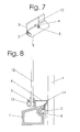
- Fig. 7
- eine Draufsicht auf eine weitere Ausführungsform der erfindungsgemäßen Befestigungsvorrichtung;
- Fig. 8
- einen Schnitt durch die Ausführungsform gemäß Fig. 7.
- Fig. 1
- a plan view of an embodiment of the fastening device according to the invention;
- Fig. 2
- a section through an embodiment of the fastening device according to the invention;
- Fig. 3
- a section through the embodiment of Figure 2, in which the holding element is shown without support member ..;
- Fig. 4
- a plan view of the support member of the embodiment of FIG. 2;
- Fig. 5
- a section through another embodiment of the fastening device according to the invention; and
- Fig. 6
- a plan view of the support member of the embodiment of FIG. 5;
- Fig. 7
- a plan view of a further embodiment of the fastening device according to the invention;
- Fig. 8
- a section through the embodiment of FIG. 7th
In Fig. 1 ist an einer Glasleiste 1 eine Scheibendichtung 2
befestigt, durch die eine Glasscheibe 3 gehalten wird. Ein
Halteelement 4 und ein Trageelement 5, die zusammen die erfindungsgemäße
Befestigungsvorrichtung bilden, sind voneinander
getrennt dargestellt.In Fig. 1 is on a
Die Schnittdarstellung in Fig. 2 zeigt, dass die Scheibendichtung
2 von einer T-förmigen Nut 6 gehalten wird. Das
Halteelement 4, das hier aus einem dünnen Blechstreifen geformt
ist, ist an seinem glasleistenseitigen Ende rechtwinklig
abgewinkelt und greift in die von der T-förmigen
Nut 6 gebildete Hinterschneidung in der Glasleiste 1 ein.
Das glasleistenferne Ende des Halteelements 4 ragt zwischen
Scheibendichtung 2 und Glasleiste 1 hervor.The sectional view in Fig. 2 shows that the
An diesem glasleistenfernen Ende des Halteelements 4 ist
das Trageelement 5 befestigt, das in Fig. 4 in Draufsicht
dargestellt ist. Ein Abstützelement 7 ist mit einer Schraube
8 am Körper des Trageelements 5 befestigt. Bei etwas gelöster
Schraube 8 kann das glasleistenferne Ende des Halteelements
4 in den Schlitz zwischen Abstützelement 7 und
Körper des Trageelements 5 eingeführt werden. Durch Anziehen
der Schraube 8 wird das Abstützelement 7 gegen den Körper
des Tragelements 5 gezogen, das glasleistenferne Ende
des Halteelements 4 wird zwischen Abstützelement 7 und Körper
des Tragelements 5 eingeklemmt. An dem gegen das Haltelement
4 fixierten Trageelement 5 kann mit Hilfe einer
Verschlusseinrichtung 9 eine nicht dargestellte Sonnenschutzeinrichtung
befestigt werden.At this Glasleistenfernen end of the
In Fig. 3 ist das Halteelement 4 ohne Trageelement dargestellt.
Die Scheibendichtung 2 ist aus Gummi und kann deswegen
mit geringem Kraftaufwand verformt werden. Durch
Schwenken des glasleistenfernen Teils des Halteelements 4
von der Glasscheibe 3 weg löst sich das abgewinkelte Ende
des Halteelements aus der T-förmigen Nut 6 und kann zwischen
Scheibendichtung 2 und Glasleiste 1 herausgezogen
werden, ohne dass eines der Teile beschädigt wird. Durch
eine umgekehrte Bewegung wird das Halteelement 4 in die
Eingriffstellung gebracht, ebenfalls ohne dass eines der
Teile beschädigt wird.In Fig. 3, the holding
Sobald das Trageelement 5 am Halteelement 4 befestigt ist,
ist die Schwenkbewegung, die das Halteelement 4 aus der
Eingriffstellung löst, nicht mehr möglich. Das Abstützelement
7 liegt an der Glasleiste 1 an, ein Schwenken des Halteelements
4 von der Glasscheibe 3 weg wird verhindert. Der
Winkel, den das Abstützelement 7 mit dem Körper des Trageelements
5 einschließt, kann verändert werden. Dadurch kann
das Abstützelement 7 an unterschiedliche Neigungswinkel der
Glasleiste 1 angepasst werden.As soon as the carrying
Auch die Gewichtskraft der an der Verschlusseinrichtung 9
befestigten Sonnenschutzeinrichtung löst das Halteelement 4
nicht aus seiner Eingriffstellung. Das an der Glasleiste 1
anliegende Abstützelement 7 hält das Halteelement 4 entgegen
der Gewichtskraft fest in der Eingriffstellung. Dies
kann unterstützt werden durch einen zusätzlichen Anschlag
10, mit dem sich die Befestigungsvorrichtung an der Glasscheibe
abstützt. Also, the weight of the at the closure device. 9
attached sun protection device releases the retaining element. 4
not from his intervention position. The on the
Fig. 5 zeigt eine weitere Ausführungsform der erfindungsgemäßen
Befestigungsvorrichtung. Hier ist auch das glasleistenferne
Ende des Halteelements 4 rechtwinklig abgewinkelt.
Das Trageelement 5, das in Fig. 6 in Draufsicht dargestellt
ist, wird waagerecht auf das Halteelement 4 aufgesteckt und
mittels eines bajonettartigen Verschlusses 11 am Halteelement
4 eingehakt. Im übrigen sind Aufbau und Funktion identisch
mit der Ausführungsform aus Fig. 2. Mit der Schraube
8 ist das Abstützelement 7 am Körper des Trageelements 5
befestigt. Das Abstützelement 7 liegt an der Glasleiste 1
an, so dass das Halteelement 4 nicht aus der Eingriffstellung
gelöst werden kann. Dies kann unterstützt werden durch
den Anschlag 10Fig. 5 shows a further embodiment of the invention
Fastening device. Here is also the glasleistenferne
Angled at the end of the holding
Fig. 7 zeigt eine weitere Ausführungsform der erfindungsgemäßen
Befestigungsvorrichtung. Sonnenschutzeinrichtungen
werden häufig seitlich durch senkrechte, parallel zur Glasscheibe
3 verlaufende Drähte 12 geführt. Die Drähte 12 werden
mit der Ausführungsform gemäß Fig. 7 befestigt. Das
Halteelement 4 ist an seinem glasleistenseitigen Ende abgewinkelt
und greift in die T-förmige Nut 6 ein. An seinem
Austritt zwischen Scheibendichtung 2 und Glasleiste 1 ist
das Halteelement 4 in Richtung der Glasscheibe 3 gebogen,
so dass das Halteelement in einem Winkel von ca. 45° auf
die Glasscheibe zuläuft. Das glasleistenferne Ende des Halteelements
ist in entgegengesetzter Richtung gebogen, so
dass es rechtwinklig von der Glasscheibe 3 weg ragt. Der
Scheitel 14 dieser letzten Biegung liegt an der Glasscheibe
3 an.Fig. 7 shows a further embodiment of the invention
Fastening device. Solar protection devices
are often laterally by vertical, parallel to the
Das Trageelement ist hier ein Stellring 5, der in ein Loch
im glasleistenfernen Ende des Halteelements 4 eingesteckt
wird. Der Draht 12 wird mittels einer Schraube 13 im Stellring
5 fixiert. Bei einer Kraft auf den Draht 12 in Belastungsrichtung,
in Fig. 8 nach oben, nutzt der Scheitel 14
die Glasscheibe 3 als Widerlager und hält das Halteelement
4 fest in der Eingriffstellung.The support element here is a
Claims (13)
Applications Claiming Priority (2)
| Application Number | Priority Date | Filing Date | Title |
|---|---|---|---|
| DE200420009270 DE202004009270U1 (en) | 2004-06-11 | 2004-06-11 | Fastening device for sun protection devices |
| DE202004009270U | 2004-06-11 |
Publications (2)
| Publication Number | Publication Date |
|---|---|
| EP1605131A2 true EP1605131A2 (en) | 2005-12-14 |
| EP1605131A3 EP1605131A3 (en) | 2007-08-22 |
Family
ID=32864831
Family Applications (1)
| Application Number | Title | Priority Date | Filing Date |
|---|---|---|---|
| EP05007303A Withdrawn EP1605131A3 (en) | 2004-06-11 | 2005-04-04 | Fixing device for solar protection devices |
Country Status (2)
| Country | Link |
|---|---|
| EP (1) | EP1605131A3 (en) |
| DE (1) | DE202004009270U1 (en) |
Cited By (1)
| Publication number | Priority date | Publication date | Assignee | Title |
|---|---|---|---|---|
| EP4234876A1 (en) | 2022-02-28 | 2023-08-30 | Suomen Visor Oy | A method for installing a sunshade in a light opening of a building element, and a building element |
Families Citing this family (7)
| Publication number | Priority date | Publication date | Assignee | Title |
|---|---|---|---|---|
| GB2423328B (en) * | 2005-04-09 | 2007-02-28 | Louver Lite Ltd | Window blind system |
| AU2007231748B2 (en) * | 2005-04-09 | 2011-11-24 | Louver-Lite Limited | Window blind system |
| GB2434824B (en) | 2006-02-01 | 2011-05-04 | Turnils | Blinds and components thereof |
| GB2440536B (en) * | 2006-08-04 | 2011-10-12 | Turnils | Blinds and Components Thereof |
| WO2008015442A1 (en) * | 2006-08-04 | 2008-02-07 | Turnils (Uk) Limited | Blinds and components thereof |
| GB2448878B (en) * | 2007-04-30 | 2012-10-24 | Turnils Uk Ltd | Tool for mounting a blind |
| FI125477B (en) * | 2014-06-18 | 2015-10-30 | Suomen Visor Oy | Bracket and method for mounting a bracket to a glazing part |
Citations (2)
| Publication number | Priority date | Publication date | Assignee | Title |
|---|---|---|---|---|
| US5000242A (en) * | 1989-02-16 | 1991-03-19 | Coddens Dean A | Window assembly including adjustable blind |
| US5611381A (en) * | 1995-11-08 | 1997-03-18 | Verosol Usa Inc. | Window having a blind between two panes of glass |
-
2004
- 2004-06-11 DE DE200420009270 patent/DE202004009270U1/en not_active Expired - Lifetime
-
2005
- 2005-04-04 EP EP05007303A patent/EP1605131A3/en not_active Withdrawn
Patent Citations (2)
| Publication number | Priority date | Publication date | Assignee | Title |
|---|---|---|---|---|
| US5000242A (en) * | 1989-02-16 | 1991-03-19 | Coddens Dean A | Window assembly including adjustable blind |
| US5611381A (en) * | 1995-11-08 | 1997-03-18 | Verosol Usa Inc. | Window having a blind between two panes of glass |
Cited By (1)
| Publication number | Priority date | Publication date | Assignee | Title |
|---|---|---|---|---|
| EP4234876A1 (en) | 2022-02-28 | 2023-08-30 | Suomen Visor Oy | A method for installing a sunshade in a light opening of a building element, and a building element |
Also Published As
| Publication number | Publication date |
|---|---|
| DE202004009270U1 (en) | 2004-08-12 |
| EP1605131A3 (en) | 2007-08-22 |
Similar Documents
| Publication | Publication Date | Title |
|---|---|---|
| EP1605131A2 (en) | Fixing device for solar protection devices | |
| DE102005040019A1 (en) | Apparatus and method for supporting objects on a vehicle wall | |
| EP1219215B1 (en) | Suspension system for picture frame | |
| DE102013108807B4 (en) | Fastening device for vehicle equipment | |
| EP1607569B1 (en) | Mounting device for solar protections | |
| EP1900899A2 (en) | Mounting device for attachment elements, in particular insect/particle protection meshes | |
| DE10239740B4 (en) | Housing inner part for a seat belt retractor | |
| DE102007008667B4 (en) | Fastening device for an attachment element | |
| DE102009042686B3 (en) | Awning i.e. trailer awning, for use in e.g. wall of building, has hanging console carrying snatching lever, where lever engages behind undercut sidebar of assigned mounting plate with ratchet tooth using assigned spring | |
| DE202018004778U1 (en) | Clamp for clamping a tubular conduit to a guide rail | |
| DE202009015319U1 (en) | Cable holder for a mounting rail | |
| DE3803335C2 (en) | Suspension device for attaching a cable sleeve to the suspension cable of an aerial cable | |
| DE102008014711A1 (en) | Roof sign carrier | |
| DE202010005966U1 (en) | Mobile windowsill | |
| EP0928875B1 (en) | Ball connecting device for lamellar blinds | |
| EP0224124A1 (en) | Anchoring device, especially an eyelet of an awning for caravans and dormobiles | |
| DE102020126347B3 (en) | Spacer, guide rail for a venetian blind or venetian blind and venetian blind and blind and method therefor | |
| DE4028898A1 (en) | Seal retainer, esp. for vehicle door seals - has transverse projection for releasable fixture to and enclosed by re=entrant opening in the sealing strip | |
| DE202009017969U1 (en) | Lift-out protection for a holding element and console for this purpose | |
| DE102013201157B4 (en) | Hanging and setting device for picture frames | |
| DE10029385A1 (en) | Clamp retainer for fixture to window frame | |
| DE102008030319B4 (en) | sliding door system | |
| EP2189694B1 (en) | Pipe clip | |
| DE202018001876U1 (en) | Holder, especially for Christmas trees | |
| DE202020005587U1 (en) | Spacer, guide rail for an external venetian blind or a Venetian blind as well as external venetian blind and Venetian blind |
Legal Events
| Date | Code | Title | Description |
|---|---|---|---|
| PUAI | Public reference made under article 153(3) epc to a published international application that has entered the european phase |
Free format text: ORIGINAL CODE: 0009012 |
|
| AK | Designated contracting states |
Kind code of ref document: A2 Designated state(s): AT BE BG CH CY CZ DE DK EE ES FI FR GB GR HU IE IS IT LI LT LU MC NL PL PT RO SE SI SK TR |
|
| AX | Request for extension of the european patent |
Extension state: AL BA HR LV MK YU |
|
| PUAL | Search report despatched |
Free format text: ORIGINAL CODE: 0009013 |
|
| AK | Designated contracting states |
Kind code of ref document: A3 Designated state(s): AT BE BG CH CY CZ DE DK EE ES FI FR GB GR HU IE IS IT LI LT LU MC NL PL PT RO SE SI SK TR |
|
| AX | Request for extension of the european patent |
Extension state: AL BA HR LV MK YU |
|
| AKX | Designation fees paid | ||
| STAA | Information on the status of an ep patent application or granted ep patent |
Free format text: STATUS: THE APPLICATION IS DEEMED TO BE WITHDRAWN |
|
| 18D | Application deemed to be withdrawn |
Effective date: 20080223 |
|
| REG | Reference to a national code |
Ref country code: DE Ref legal event code: 8566 |