Background of the Invention
1. Field of the Invention
The present invention relates to particles, a method for
manufacturing the particles, and an ink composition.
2. Description of the Related Art
As image recording methods of forming an image on a medium
to be recorded, e.g., paper, on the basis of image data signals,
an electrophotographic system, a sublimation type and a melting
type heat transfer system, and an ink jet system are used. The
electrophotographic system requires a process of forming an
electrostatic latent image on a photosensitive drum by charge
and exposure, so that the system is complicated and the
apparatus is expensive. The price of the apparatus is
inexpensive as for the heat transfer system, but the system
uses ink ribbons, so that it is high in running cost and leaves
wastes. On the other hand, in the ink jet system, since the
apparatus is inexpensive and an image is directly formed on
a medium to be recorded by jetting inks on only a required image
area, so that ink can be efficiently used and running cost is
low. Further, the ink jet system is low in noise and excellent
as an image recording system.
Ink jet recording systems include, for example, a system
of jetting ink droplets by the pressure of vapor generated by
the heat of an exothermic element, a system of jetting ink
droplets by the mechanical pressure pulse generated by
piezoelectric elements, and a system of jetting ink droplets
containing charged particles by utilizing electrostatic field
(refer to U.S. Patent 6,158,844, Japanese Patent 3315334).
Methods of jetting ink droplets by vapor or mechanical pressure
cannot control the flying direction of ink droplets and it is
difficult to correctly land ink droplets on a desired point
of a medium to be recorded on due to distortion of ink nozzles
and convection of air.
On the other hand, since a method of using electrostatic
field controls the flying direction of ink droplets by
electrostatic field, it is possible to correctly land ink
droplets on a desired point. Accordingly, this system is
useful as image-formed matters (printed matters) of high
quality can be produced.
As the ink composition to be used in ink jet recording
using electrostatic field, an ink composition comprising a
dispersion medium and charged particles containing at least
a coloring material (refer to U.S. Patent 5,952,048, JP-A-8-291267
(the term "JP-A" as used herein refers to an "unexamined
published Japanese patent application")) is used. An ink
composition containing a coloring material can form inks of
four colors of yellow, magenta, cyan and black by changing
coloring materials, and further special color inks of gold and
silver can be formed. Accordingly, this system is useful as
color image-formed matters (printed matters) can be produced.
Summary of the Invention
Ink compositions used in ink jet recording are generally
manufactured by kneading a coloring material and a polymer with
heating, pulverizing the kneaded product by a dry method to
obtain particles, adding a dispersion medium and a dispersant
thereto to make the particles finer and at the same time to
disperse the fine particles in the dispersion medium, and
further adding a charge adjustor to give electrical charge to
the fine particles. However, related ink compositions
manufactured in these processes have a problem that particles
adhere to the nozzle of ink jet head (ejecting opening) of ink
jet recording apparatus, which sometimes causes clogging.
Further, the particles precipitate and are not redispersed even
by stirring when these ink compositions are preserved for a
long period of time, and the preservation stability of the ink
compositions is not good.
Accordingly, the objects of the invention are to provide
particles capable of solving the above problems, to provide
a method for manufacturing the particles, and to provide an
ink composition. More specifically, the objects of the
invention are to provide particles that hardly adhere to the
nozzle of ink jet head of ink jet recording apparatus by
inhibiting the interaction functioning among particles and can
also improve the preservation stability when used as the
component of the composition of ink for ink jet recording, to
provide a method for manufacturing the particles, and to
provide an ink composition.
The invention is as follows.
wherein a volume average particle size of the fine
particles after finishing the dispersing is less than 0.7 µm,
and a volume average particle size of the particles after
finishing the heating is from 0.7 to 5.0 µm. (3) The method for manufacturing particles as described
in (1) above,
wherein a volume average particle size of the particles
after finishing the heating is 1.2 times or more than a volume
average particle size of the fine particles after finishing
the dispersing. (4) Particles containing a coloring material and a
polymer,
wherein a redispersibility of the particles in a
dispersion medium is in a range of from 50 to 100%. (5) An ink composition comprising particles containing
a coloring material and a polymer dispersed in a dispersion
medium,
wherein a redispersibility of the particles in the
dispersion medium is in a range of from 50 to 100%.
Brief Description of the Drawings
Fig. 1 is a general view typically showing an example
of ink jet recording apparatus for use in the invention;
Fig. 2 is an oblique view showing the constitution of
the ink jet head of ink jet recording apparatus for use in the
invention (for simplification, the edge of the guard electrode
at each ejecting part is not shown); and
Fig. 3 is a cross section of side view of Fig. 2 showing
the state of the distribution of charged particles in the case
where a plurality of ejecting parts of ink jet head are used
(corresponding to the view X-X in Fig. 2).
Detailed Description of the Invention
The invention is described in detail below.
The particles manufactured according to the invention
are useful particularly as the component of the composition
of ink for ink jet recording, but the use of the particles
manufactured according to the invention is not limited thereto.
For example, a liquid developer for electrophotography and
display elements for electronic paper and digital paper are
exemplified.
The case where the particles manufactured according to
the invention are used as the component of the composition of
ink for ink jet recording, in particular for ink jet recording
of ejecting charged particles by utilizing an electrostatic
field, is described below. Such a composition is manufactured
by dispersing a mixture comprising at least a coloring material
and a polymer in a dispersion medium to obtain particles through
a dispersing process and a heating process of the invention,
and further adding a charge adjustor to give electrical charge
to the particles. The uses of the particles manufactured
according to the invention are not limited to the following
description.
Dispersion medium:
A dispersion medium is preferably a dielectric liquid
having high electrical resistivity, specifically 1010 Ω cm or
higher. If a dispersion medium having low electrical
resistivity is used, electrical continuity occurs between
contiguous recording electrodes, so that such a dispersion
medium is not preferred for the present invention. The
dielectric constant of a dielectric liquid is preferably 5 or
less, more preferably 4 or less, and still more preferably 3.5
or less. When the dielectric constant of a dielectric liquid
is in this range, electric field effectively acts upon the
charged particles in the dielectric liquid and preferred.
As the dispersion media for use in the invention,
straight chain or branched aliphatic hydrocarbon, alicyclic
hydrocarbon, aromatic hydrocarbon, halogen substitution
products of these hydrocarbons, and silicone oil are
exemplified. For example, hexane, heptane, octane, isooctane,
decane, isodecane, decalin, nonane, dodecane, isododecane,
cyclohexane, cyclooctane, cyclodecane, toluene, xylene,
mesitylene, Isopar-C, Isopar-E, Isopar-G, Isopar-H, Isopar-L
and Isopar-M (Isopar is the trade name of Exxon), Shellsol 70
and Shellsol 71 (Shellsol is the trade name of Shell Oil Co.),
Amsco OMS and Amsco 460 solvents (Amsco is the trade name of
Spirits Co.), and KF-96L (trade name, manufactured by Shin-Etsu
Chemical Co., Ltd., Silicone Division) can be used alone or
as a mixture. The content of dispersion medium in all the ink
composition is preferably from 20 to 99 weight%. When the
content of a dispersion medium is 20 weight% or more, particles
containing a coloring material can be well dispersed in the
dispersion medium, and 99 weight% or less can suffice the
content of a coloring material.
Coloring material:
Well-known dyes and pigments can be used as the coloring
materials in the invention, and they can be selected according
to the use and the purpose. For example, from the viewpoint
of the tone of image-recorded matters (printed matters), it
is preferred to use pigments (for example, see Ganryo Bunsan
Anteika to Hyomen Shori Gijutsu·Hyoka (Pigment Dispersion
Stabilization and Techniques of Surface Treatment·Evaluation),
First Edition, published by Gijutsu Joho Kyokai (Dec. 25, 2001).
By changing coloring materials, inks of four colors of yellow,
magenta, cyan and black can be formed. In particular, by using
the pigments for use as offset printing inks and proofs, the
same tone as the offset prints can be obtained and preferred.
As pigments for yellow inks, monoazo pigments, e.g., C.I.
Pigment Yellow 1 and C.I. Pigment Yellow 74, disazo pigments,
e.g., C.I. Pigment Yellow 12 and C.I. Pigment Yellow 17,
non-benzidine series azo pigments, e.g., C.I. Pigment Yellow
180, azo lake pigments, e.g., C.I. Pigment Yellow 100,
condensed azo pigments, e.g., C.I. Pigment Yellow 95, acid dye
lake pigments, e.g., C.I. Pigment Yellow 115, basic dye lake
pigments, e.g., C.I. Pigment Yellow 18, anthraquinone pigments,
e.g., Flavanthrone Yellow, isoindolinone pigments, e.g.,
Isoindolinone Yellow 3RLT, quinophthalone pigments, e.g.,
Quinophthalone Yellow, isoindoline pigments, e.g.,
Isoindoline Yellow, nitroso pigments, e.g., C.I. Pigment
Yellow 153, metal complex salt azomethine pigments, e.g., C.I.
Pigment Yellow 117, and isoindolinone pigments, e.g., C.I.
Pigment Yellow 139 are exemplified.
As pigments for magenta inks, monoazo pigments, e.g.,
C.I. Pigment Red 3, disazo pigments, e.g., C.I. Pigment Red
38, azo lake pigments, e.g., C.I. Pigment Red 53:1 and C.I.
Pigment Red 57:1, condensed azo pigments, e.g., C.I. Pigment
Red 144, acid dye lake pigments, e.g., C.I. Pigment Red 174,
basic dye lake pigments, e.g., C.I. Pigment Red 81,
anthraquinone pigments, e.g., C.I. Pigment Red 177, thioindigo
0pigments, e.g., C.I. Pigment Red 88, perinone pigments, e.g.,
C.I. Pigment Red 194, perylene pigments, e.g., C.I. Pigment
Red 149, quinacridone pigments, e.g., C.I. Pigment Red 122,
isoindolinone pigments, e.g., C.I. Pigment Red 180, and
Alizarin lake pigments, e.g., C.I. Pigment Red 83 are
exemplified.
As pigments for cyan inks, disazo pigments, e.g., C.I.
Pigment Blue 25, phthalocyanine pigments, e.g., C.I. Pigment
Blue 15, acid dye lake pigments, e.g., C.I. Pigment Blue 24,
basic dye lake pigments, e.g., C.I. Pigment Blue 1,
anthraquinone pigments, e. g. , C.I. Pigment Blue 60, and alkali
blue pigments, e.g., C.I. Pigment Blue 18 are exemplified.
As pigments for black inks, organic pigments, e.g.,
aniline black pigments, and iron oxide pigments, and carbon
black pigments, e.g., furnace black, lamp black, acetylene
black and channel black are exemplified.
Further, processed pigments typified by Microlith
Pigments, e.g., Microlith-A, -K and -T can also be preferably
used. The specific examples thereof include Microlith Yellow
4G-A, Microlith Red BP-K, Microlith Blue 4G-T, and Microlith
Black C-T.
Various kinds of pigments can be used according to
necessity, e.g., as pigments for white inks, calcium carbonate
and titanium oxide pigments, as pigments for silver inks,
aluminum powders, and as pigments for golden inks, copper
alloys are used.
It is preferred to use fundamentally one kind of pigment
for one color from the point of the simplicity of manufacture
of ink, but it is also preferred to use two or more pigments
in combination in some cases for the purpose of adjusting the
hue, such as the mixture of phthalocyanine with carbon black
for black ink. Further, pigments may be subjected to surface
treatment before use by well-known methods, e.g., rosin
treatment (the above mentioned Ganryo Bunsan Anteika to Hyomen
Shori Gijutsu·Hyoka).
The pigment content in all the ink composition is
preferably from 0.1 to 50 weight%. The content of 0.1 weight%
or more is sufficient as the pigment content and sufficiently
good coloring can be obtained in the printed matters, and when
the content is 50 weight% or less, particles containing
coloring materials can be well dispersed in a dispersion medium.
The pigment content is more preferably from 1 to 30 weight%.
Covering agent:
In the present invention, it is preferred that coloring
materials such as pigments are dispersed (to be made particles)
in a dispersion medium in the state of being covered with a
covering agent rather than to be directly dispersed (to be made
particles). By covering with a covering agent, the electric
charge of the coloring material is masked and desired charge
characteristics can be obtained. In the invention, after ink
jet recording on a recording medium ("a recording medium" means
a medium on which an image is recorded, such as paper and the
like), the medium is subjected to fixation with a heating means
such as a heat roller, and at this time the covering agent is
melted by heat and fixation is efficiently effected.
As the examples of covering agents, e.g., rosins,
rosin-modified phenol resin, alkyd resin, (meth)acrylic
polymer, polyurethane, polyester, polyamide, polyethylene,
polybutadiene, polystyrene, polyvinyl acetate, an acetal-modified
product of polyvinyl alcohol, and polycarbonate are
exemplified. Of these covering agents, from the easiness of
formation of particles, polymers having a weight average
molecular weight of from 2,000 to 1,000,000, and the degree
of polydispersion (weight average molecular weight/number
average molecular weight) of from 1.0 to 5.0 are preferred.
Further, from the easiness of fixation, polymers having any
one of a softening point, a glass transition point and a melting
point of from 40 to 120°C are preferred.
The polymers particularly preferably used in the
invention as the covering agent are polymers containing at
least any one of the constitutional units represented by the
following formulae (1) to (4).
In the above formulae, X11 represents an oxygen atom
or-N(R13)-; R11 represents a hydrogen atom or a methyl group;
R12 represents a hydrocarbon group having from 1 to 30 carbon
atoms; R13 represents a hydrogen atom or a hydrocarbon group
having from 1 to 30 carbon atoms; R21 represents a hydrogen atom
or a hydrocarbon group having from 1 to 20 carbon atoms; and
R31, R32 and R41 each represents a divalent hydrocarbon group
having from 1 to 20 carbon atoms; and the hydrocarbon groups
represented by R12, R21, R31, R32 and R41 may have an ether bond,
an amino group, a hydroxyl group or a halogen substituent.
A polymer containing a constitutional unit represented
by formula (1) can be obtained by radical polymerization of
a corresponding radical polymerizable monomer by known methods.
As the radical polymerizable monomers to be used, (meth) acrylic
esters, e.g., methyl (meth)acrylate, ethyl (meth)acrylate,
propyl (meth)acrylate, butyl (meth)acrylate, hexyl (meth)-acrylate,
octyl (meth)acrylate, 2-ethylhexyl (meth)acrylate,
dodecyl (meth)acrylate, stearyl (meth)acrylate, cyclohexyl
(meth)acrylate, phenyl (meth)acrylate, benzyl (meth)acrylate,
and 2-hydroxyethyl (meth)acrylate, and (meth)acrylamides,
e.g., N-methyl(meth)acrylamide, N-propyl(meth)acrylamide,
N-phenyl(meth)acrylamide, and N,N-dimethyl(meth)acrylamide
are exemplified.
A polymer containing a constitutional unit represented
by formula (2) can be obtained by radical polymerization of
a corresponding radical polymerizable monomer by known methods.
As the radical polymerizable monomers to be used, e.g.,
ethylene, propylene, butadiene, styrene and 4-methylstyrene
are exemplified.
A polymer containing a constitutional unit represented
by formula (3) can be obtained by dehydration condensation of
a corresponding dicarboxylic acid, or acid anhydride and diol
by known methods. As the dicarboxylic acids to be used,
succinic anhydride, adipic acid, sebacic acid, isophthalic
acid, terephthalic acid, 1,4-phenylenediacetic acid and
diglycolic acid are exemplified. As the diols to be used,
ethylene glycol, 1,2-propanediol, 1,3-propanediol, 1,4-butanediol,
1,6-hexanediol, 1,10-decanediol, 2-butene-1,4-diol,
1,4-cyclohexanediol, 1,4-cyclohexanedimethanol,
1,4-benzenedimethanol, and diethylene glycol are exemplified.
A polymer containing a constitutional unit represented
by formula (4) can be obtained by dehydration condensation of
a corresponding carboxylic acid having a hydroxyl group by
known methods, or ring opening polymerization of a cyclic ester
of a corresponding carboxylic acid having a hydroxyl group by
known methods. As the carboxylic acids having a hydroxyl group
or cyclic esters thereof to be used, 6-hydroxyhexanoic acid,
11-hydroxyundecanoic acid, hydroxybenzoic acid, and
ε-caprolactone are exemplified.
The polymers containing at least any one of the
constitutional units represented by formulae (1) to (4) may
be homopolymers of the constitutional units represented by
formulae (1) to (4), or they may be copolymers with other
constitutional units. These polymers may be used alone as the
covering agents or two or more of these covering agents may
be used in combination.
The covering agent content in the total ink composition
is preferably from 0.1 to 40 weight%. The content of 0.1
weight% or more is sufficient as the covering agent content
and sufficient fixation can be obtained, and when the content
is 40 weight% or less, good particles containing a coloring
material and a covering agent can be formed.
Dispersant:
In the invention, a mixture of a coloring material and
a covering agent is dispersed (made particles) in a dispersion
medium, and it is preferred to use a dispersant to inhibit
particles from precipitating.
The examples of the dispersants include surfactants
typified by sorbitan fatty acid esters, e.g., sorbitan
monooleate, and polyethylene glycol fatty acid esters, e.g.,
polyoxyethylene distearate are exemplified. In addition,
e.g., copolymers of styrene and maleic acid, and amine-modified
products of the copolymers, copolymers of styrene and
(meth)acrylic compounds, (meth)acrylic polymers, copolymers
of polyethylene and (meth)acrylic compounds, rosin, BYK-160,
162, 164, 182 (polyurethane polymers, manufactured by BYK
Chemie), EFKA-401 and 402 (acrylic polymers, manufactured by
EFKA Co.), and Solspers 17000 and 24000 (polyester polymers,
manufactured by Zeneca Agrochemicals Co., Ltd.) are
exemplified. From the viewpoint of the long term storage
stability of an ink composition, polymers having a weight
average molecular weight of from 1,000 to 1,000,000, and the
degree of polydispersion (weight average molecular
weight/number average molecular weight) of from 1.0 to 7.0 are
preferred. To use graft polymers or block polymers is most
preferred.
The polymers particularly preferably used in the
invention are graft polymers containing a polymer component
comprising at least either one constitutional unit represented
by the following formula (5) or (6), and a polymer component
containing a constitutional unit represented by the following
formula (7) at least as the graft chain.
wherein X
51 represents an oxygen atom or -N(R
53)-; R
51
represents a hydrogen atom or a methyl group; R
52 represents
a hydrocarbon group having from 1 to 10 carbon atoms; R
53
represents a hydrogen atom or a hydrocarbon group having from
1 to 10 carbon atoms; R
61 represents a hydrogen atom, a
hydrocarbon group having from 1 to 20 carbon atoms, a halogen
atom, a hydroxyl group, or an alkoxyl group having from 1 to
20 carbon atoms; X
71 represents an oxygen atom or -N(R
73)-; R
71
represents a hydrogen atom or a methyl group; R
72 represents
a hydrocarbon group having from 4 to 30 carbon atoms; and R
73
represents a hydrogen atom or a hydrocarbon group having from
1 to 30 carbon atoms; and the hydrocarbon groups represented
by R
52 and R
72 may contain an ether bond, an amino group, a
hydroxyl group or a halogen substituent.
The above graft polymer can be obtained by polymerizing
a radical polymerizable monomer represented by formula (7)
preferably in the presence of a chain transfer agent,
introducing a polymerizable functional group to the terminals
of the obtained polymer, and further copolymerizing with a
radical polymerizable monomer represented by formula (5) or
(6).
As the radical polymerizable monomers corresponding to
formula (5), e.g., (meth)acrylic esters, e.g., methyl
(meth)acrylate, ethyl (meth)acrylate, propyl (meth)acrylate,
butyl (meth)acrylate, hexyl (meth)acrylate, cyclohexyl
(meth)acrylate, phenyl (meth)acrylate, benzyl (meth)acrylate,
and 2-hydroxyethyl (meth)acrylate, and (meth)acrylamides,
e.g., N-methyl(meth)acrylamide, N-propyl(meth)acrylamide,
N-phenyl(meth)acrylamide, and N,N-dimethyl(meth)acrylamide
are exemplified.
As the radical polymerizable monomers corresponding to
formula (6), e.g., styrene, 4-methylstyrene, chlorostyrene
and methoxystyrene are exemplified.
As the radical polymerizable monomers corresponding to
formula (6), e.g., hexyl (meth) acrylate, octyl (meth) acrylate,
2-ethylhexyl (meth)acrylate, dodecyl (meth)acrylate and
stearyl (meth)acrylate are exemplified.
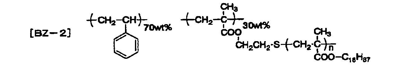
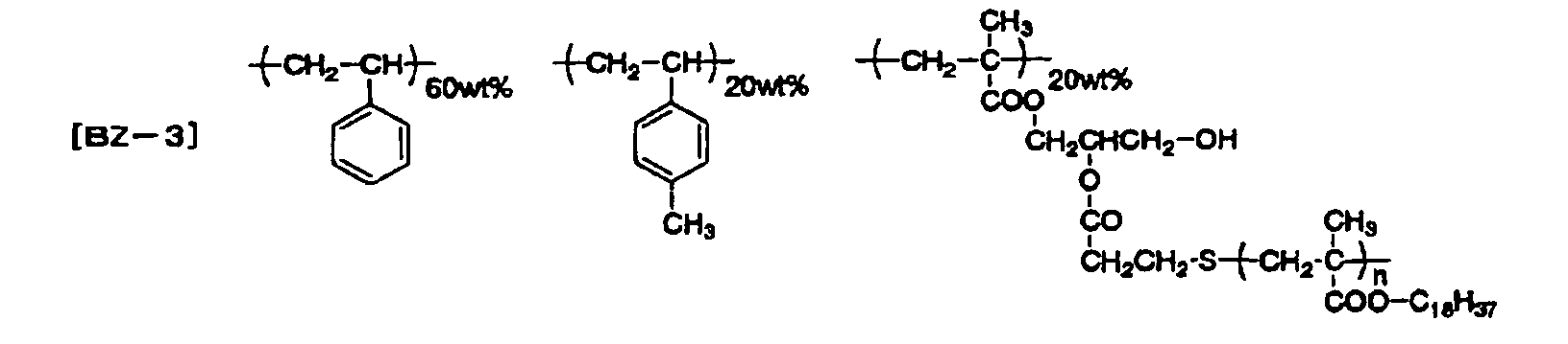
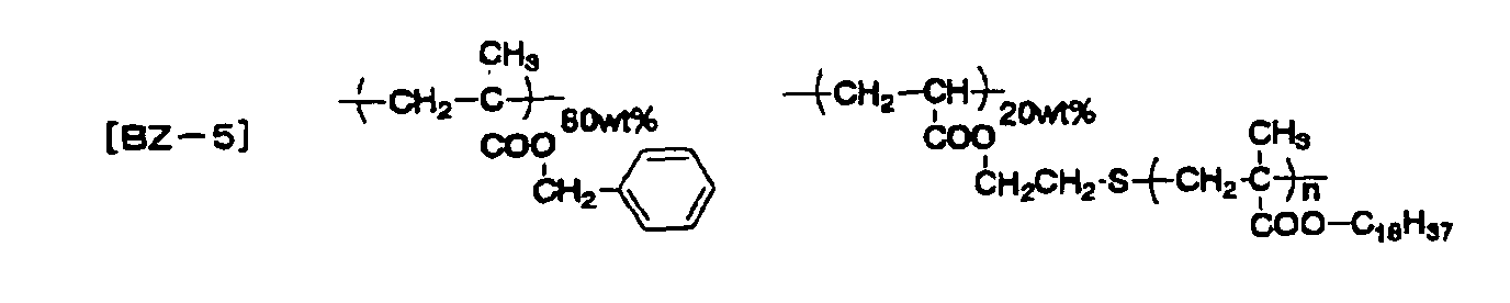
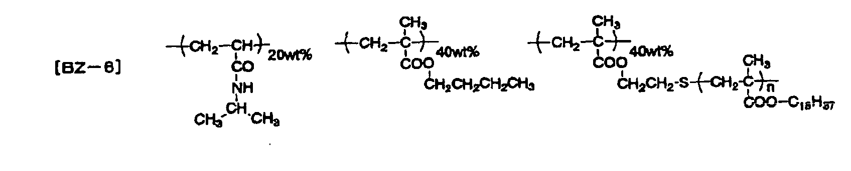
As the specific examples of these graft polymers, the
polymers represented by the following formulae are
exemplified.
The graft polymers containing a polymer component
comprising at least either one constitutional unit represented
by formula (5) or (6), and a polymer component containing a
constitutional unit represented by formula (7) at least as the
graft chain may contain a constitutional unit represented by
formula (5) and/or (6), and a constitutional unit represented
by formula (7) alone, or may contain other constitutional unit.
The preferred composition ratio of the polymer component having
a graft chain to other polymer component is from 10/90 to 90/10.
When the composition ratio is in this range, a good particle
forming property can be obtained, so that a desired particle
size is liable to be obtained and preferred. These polymers
may be used alone as a dispersant, or two or more polymers may
be used in combination.
The content of a dispersant in the total ink composition
is preferably from 0.01 to 30 weight%. When the content of
a dispersant is in this range, a good particle forming property
can be obtained, so that a desired particle size can be
obtained.
Charge adjustor:
In the invention, it is further preferred to use a charge
adjustor in combination for controlling the charge quantity
of particles.
As preferred charge adjustors, metal salt of organic
carboxylic acid, e.g., zirconium naphthenate and zirconium
octanoate, ammonium salt of organic carboxylic acid, e.g.,
tetramethylammonium stearate, metal salt of organic sulfonic
acid, e.g., sodium dodecylbenzenesulfonate and magnesium
dioctylsulfosuccinate, ammonium salt of organic sulfonic acid,
e.g., tetrabutylammonium toluenesulfonate, a polymer having
a carboxylic acid group on the side chain, e.g., a polymer
having a carboxylic acid group obtained by modifying a
copolymer of styrene and maleic anhydride with amine, etc.,
a polymer having a carboxylate anionic group on the side chain,
e.g., a copolymer of stearyl methacrylate and tetramethylammonium
methacrylate, etc., a polymer having a nitrogen atom
on the side chain, e.g., a copolymer of styrene and
vinylpyridine, etc., and a polymer having an ammonium group
on the side chain, e.g., a copolymer of butyl methacrylate and
N-(2-methacryloyloxyethyl)-N,N,N-trimethylammoniumtosylate,
etc., are exemplified. The electric charge given to particles
may be positive charge or negative charge. The content of a
charge adjustor in the total ink composition is preferably from
0.0001 to 10 weight%.
Other components:
Further, antibacterial agents for preventing rottenness
and surfactants for controlling the surface tension can be used
in the invention, according to purpose.
A dispersing process in the invention is described below.
The dispersing process is a process of dispersing a
mixture of a coloring material and a polymer (a covering agent)
with beads for dispersion to make fine particles. As beads
for dispersion, steel beads, glass beads, and ceramic beads,
e.g., zirconia, titania, alumina and silicon nitride are used.
The particle size of beads is preferably from 0.05 to 5 mm,
more preferably from 0.1 to 3 mm. For forming desired fine
particles, the dispersing process may be performed a plurality
of times by changing the kind and particle size of the beads
for dispersion.
Apparatus such as a kneader, a dissolver, a mixer, a high
speed disperser, a sand mill, a roll mill, a ball mill, an
attritor, and a beads mill (see the above mentioned Ganryo
Bunsan Anteika to Hyomen Shori Gijutsu·Hyoka) are used for
dispersion.
The temperature of the dispersing process is preferably
lower than the glass transition temperature and the softening
point of a polymer. The time of the dispersing process is
preferably from 30 minutes to 10 hours. The fine particles
thus obtained after dispersing process preferably have a volume
average particle size of less than 0.7 µm, preferably from 0.1
to 0.65 µm. The particle size of the fine particles is smaller
than the aiming desired particle size.
A mixture of a coloring material and a polymer can be
obtained by blending both components by a dry method and the
above dispersing apparatus are used for the blending. The
ratio of long particle size/short particle size of the powder
particles obtained by a dry method is preferably from 1 to 5.
Further, the ratio of volume average particle size/number
average particle size is preferably 10 or less.
After finishing the dispersing process, the beads for
dispersion are removed, and then a heating process of heating
the obtained fine particles is performed to increase the
particle size of the fine particles.
The heating temperature in the heating process is
preferably higher than the glass transition temperature and
the softening point of a polymer, and it may be selected
optionally, but a preferred temperature is, e.g., from 35 to
120°C. The time of the heating process is preferably from 30
minutes to 10 hours. The volume average particle size of the
thus-obtained particles after finishing the heating process
is preferably from 0.7 to 5.0 µm, more preferably from 0.7 to
3.0 µm. Further, the volume average particle size of the
particles after finishing the heating process is 1.2 times or
more, more preferably 1.5 times or more, than the volume average
particle size of the fine particles after finishing the
dispersing process. Particles having a desired particle size
are obtained according to the heating process.
The volume average particle size of particles can be
measured, for example, by a centrifugal precipitation method
with an apparatus, e.g., ultracentrifugal automatic particle
size distribution-measuring apparatus CAPA-700 (manufactured
by HORIBA LTD.). The volume average particle size of particles
can be adjusted by the kind and addition amount of a dispersant
and apparatus used for dispersion.
As described above, related ink compositions are
manufactured by kneading a coloring material and a polymer with
heating, pulverizing the kneaded product by a dry method to
obtain particles, adding a dispersion medium and a dispersant
thereto to make the particles finer and at the same time to
disperse the fine particles in the dispersion medium, and
further adding a charge adjustor to give electrical charge to
the fine particles, but related ink compositions have a problem
that particles adhere to the nozzle of ink jet head of ink jet
recording apparatus, which sometimes causes clogging.
Further, the particles precipitate and are not redispersed even
by stirring when these ink compositions are preserved for a
long period of time, and the preservation stability of the ink
compositions is not good.
In the invention, particles having a smaller particle
size than a desired size are formed in a dispersing process,
and then the particle size is increased in a heating process
to thereby obtain particles having a desired size. The pigment,
i.e., the coloring material, is difficult to be bared on the
surface of the particles by these processes, so that the
interaction functioning among particles can be inhibited.
Specifically, in fine particles formed by a dispersing process,
the pigment is bared on the surface of the particles by the
powerful works of the beads for dispersion, so that the
interaction among particles is strong, as a result the
particles are liable to adhere to the nozzle of ink jet head
of ink jet recording apparatus and dry. Further, the particles
are liable to agglomerate during preservation. However, in
the invention, a polymer covers a pigment by a succeeding
heating process, so that the pigment is hardly bared on the
surface of the particles and the interaction functioning among
particles can be inhibited, in addition the dry adhesion of
the particles is difficult to occur and the agglomeration
during preservation can also be reduced. When heating is
performed in the dispersing process using beads for dispersion,
covering of a pigment by a polymer is not effectual and a
drawback such as the decomposition of the pigment arises.
A charge adjustor may be added in either the dispersing
process or a heating process.
The redispersibility in a dispersion medium of the
particles of the invention manufactured according to the above
manufacturing method is in the range of from 50 to 100%,
preferably from 70 to 100%. Accordingly, the redispersibility
in a dispersion medium of an ink composition obtained by
dispersing the particles of the invention in a dispersion
medium is in the range of from 50 to 100%, preferably from 70
to 100%.
Redispersibility in the invention means as follows:
That is, when a composition containing particles and a
dispersion medium is dried, the dispersion medium is evaporated
to obtain a solid, and a dispersion medium is added to the solid
to redisperse (dissolve) the solid, the weight% of the solid
redispersed at this time means redispersibility in the
invention, and the redispersibility is a value measured by the
following measuring method. Hereafter, a dispersion medium
used for the measurement of redispersibility is the same as
a dispersion medium contained in a dispersed composition. For
example, when Isopar G is contained as a dispersion medium
Isopar G is used for the measurement of redispersibility.
Specific measuring method of redispersibility:
Ten (10) grams of a composition is spread in a Petri dish
and naturally dried at room temperature (the drying time is
1 hour when Isopar G is used as a dispersant) to thereby obtain
a solid.
Ten (10) grams of a dispersant is added to the obtained
solid, followed by standing for 30 minutes at room temperature.
The mixture is filtered through a nylon filter of 42 µm
meshes.
The residue on the nylon filter is naturally dried at
room temperature.
The redispersibility is computed according to the
following equation.
[ (The weight of the solid - the weight of the residue) /the
weight of the solid] x 100 (%)
As the ink composition for use in the invention, it is
preferred to prepare an ink composition for initial charge and
an ink composition for replenishment and replenish the ink
composition for replenishment to supply the reduction in
concentration of particles due to the ejection of the ink
composition for initial charge, and at the same time, make the
concentration of the solids content of the replenishment ink
composition higher than that of the ink composition for initial
charge.
The concentrations of the solids contents of an ink
composition for initial charge and a replenishing ink
composition are not particularly restricted, but it is
preferred that the concentration of the solids content of an
ink composition for initial charge be from 1 to 40 weight%,
the concentration of a replenishment ink composition from 2
to 60 weight%, and the ratio of the concentrations of the solids
contents of an ink composition for initial charge and a
replenishment ink composition of the latter/the former ratio
be set at 1.05 to 10.0, more preferably from 1.1 to 7.0. By
satisfying these conditions, a good ejecting characteristic
can be obtained, and the mixing failure of the ink composition
for initial charge and the replenishment ink composition does
not occur. The preferred solids content concentration of an
ink composition for initial charge is from 3 to 30 weight%,
and that of a replenishment ink composition is from 5 to 50
weight%.
The concentration of the solids content can be computed
on the basis of the weight change by heating an ink composition
to remove the volatile content, e.g., it can be computed on
the basis of the weight change by drying an ink composition
on a hot plate at 145°C for 2 hours.
In the invention, the electric conductivity at 20°C of
an ink composition for initial charge is preferably from 10
to 50,000 pS/cm (from 1 to 5,000 nS/m), and that of an ink
composition for replenishment is preferably from 50 to 100, 000
pS/cm (from 1 to 10, 000 nS/m). When the electric conductivity
of an ink composition is in this range, a good ejecting
characteristic can be obtained. By making the electric
conductivity of a replenishment ink composition higher than
that of an ink composition for initial charge, an ejecting
characteristic can be maintained for long hours, so that more
preferred. The electric conductivity of an ink composition
can be adjusted by the kinds and the addition amounts of a
dispersion medium and a charge adjustor to be used.
In the invention, the coefficient of viscosity of an ink
composition at 20°C is preferably in the range of from 0.5 to
50 mPa·s. When the coefficient of viscosity is in this range,
a good ejecting characteristic can be obtained. The
coefficient of viscosity of an ink composition can be adjusted
by the kinds and the addition amounts of a dispersion medium
and polymer components, e.g., a dispersant, dissolved in the
dispersion medium to be used. The coefficient of viscosity
of an ink composition can also be adjusted by the use of a
surfactant.
Ink jet recording apparatus:
The above ink composition is recorded on a recording
medium by an ink jet recording system, and it is preferred in
the invention to use an ink jet recording system utilizing
electrostatic field. An ink jet recording system utilizing
electrostatic field is a system of applying voltage between
a control electrode and a back electrode in rear of a recording
medium to whereby concentrate the charged particles of an ink
composition at the jetting position by the electrostatic force,
and jetting the ink composition from the jetting position to
the recording medium. The voltage applied between a control
electrode and a back electrode is such that, e.g., the control
electrode is a positive electrode and the back electrode is
a negative electrode when the charged particles are positively
charged. The same effect can be obtained by charging a
recording medium in place of applying voltage to a back
electrode.
As an ink jet system, for example, a system of jetting
ink from a needle-like tip such as an injector is known, and
recording can be performed with the ink composition of the
invention. However, the replenishment of charged particles
after charged particles are concentrated and ejected is
difficult, so that it is difficult to perform recording stably
for a long period of time. When ink is circulated for forcedly
replenishing charged particles, since a method for overflowing
the ink from the tip of an injection needle is used, the shape
of meniscus at the tip of the injection needle of ejection
position is not stable, and stable recording is difficult, and
so this system is suitable for short-term recording.
On the other hand, a method for circulating an ink
composition without overflowing the ink composition from an
ejecting opening is preferably used. For example, according
to a system wherein ink is circulated in an ink chamber having
an ejecting opening, a control electrode is formed around the
ejecting opening, an ink guide is present in the ejecting
opening, whose tip faces on the side of a recording medium,
and the concentrated ink droplets are ejected from the tip of
the ink guide by the application of voltage to the control
electrode, recording can be performed stably for a long period
of time, since the replenishment of charged particles by the
circulation of the ink and the meniscus stability at the
ejecting position can be compatible. Further in the system,
since the exposure of the ink to the air is limited only to
the ejecting opening, evaporation of the solvent is inhibited
and physical characteristics of the ink are stabilized, so that
the system can be very preferably used in the invention.
An example of the structure of an ink jet recording
apparatus suitable to use the ink composition of the invention
is described below.
In the first place, the outline of the apparatus of
performing four-color printing on one side of a recording
medium shown in Fig. 1 is described. Ink jet recording
apparatus 1 shown in Fig. 1 is equipped with jet head 2
comprising jet heads 2C, 2M, 2Y and 2K of four colors for
performing full color image formation, ink circulatory system
3 for feeding inks to jet head 2 and recovering inks from jet
head 2, head driver 4 for driving jet head 2 by the output of
the outside apparatus such as a computer and RIP not shown,
and position controlling means 5. Ink jet recording apparatus
1 is further equipped with carrier belt 7 stretching on three
rollers 6A, 6B and 6C, carrier belt position detecting means
8 consisting of an optical sensor and the like capable of
detecting the position of carrier belt 7 in the width direction,
electrostatic suction means 9 for maintaining recording medium
P on carrier belt 7, and destaticizing means 10 and mechanical
means 11 for peeling away recording medium P from carrier belt
7 after conclusion of image formation. Feed roller 12 and guide
13 for feeding recording medium P from a stocker not shown to
carrier belt 7, and fixing means 14 and guide 15 for fixing
the inks on recording medium P after being peeled and carrying
the recording medium to a stocker of discharged paper not shown
are arranged on the upstream and the downstream of carrier belt
7. In the inside of ink jet recording apparatus 1 are arranged
recording medium position-detecting means 16 at the counter
position to jet head 2 with carrier belt 7 between, exhaust
fan 17 for recovering the vapor of the solvent occurring from
the ink composition, and a solvent recovery part comprising
solvent vapor adsorbing material 18, and the vapors in the
inside of the apparatus are exhausted through the recovery
part.
As feed rollers 12, well-known rollers can be used, and
feed rollers 12 are arranged so that the feeding ability to
recording medium P is increased. It is preferred to remove
dirt and paper powder adhered on recording medium P. Recording
medium P fed by feed rollers 12 is carried to carrier belt 7
through guide 13. The back surface of carrier belt 7
(preferably a metal back surface) is provided via roller 6A.
The recording medium carried is electrostatically adsorbed on
the carrier belt by electrostatic suction means 9. In Fig.
1, electrostatic suction is performed by a Scorotron charger
connected to negative high voltage power supply. The
recording medium is electrostatically sucked on carrier belt
7 without floatation by electrostatic suction means 9 and, at
the same time, the surface of the recording medium is uniformly
charged. The electrostatic suction means is also utilized as
a charging means of recording medium P here, but a charging
means may be provided separately. Charged recording medium
P is carried to the jet head part by means of carrier belt 7,
and electrostatic ink jet image formation is performed by
piling recording signal voltage with charged potential as bias.
Image-recorded recording medium P is destaticized by
destaticizing means 10, peeled away from carrier belt 7 by
mechanical means 11, and carried to the fixing part. Peeled
recording medium P is carried to image fixing means 14 and fixed.
The fixed recording medium P is discharged to a stocker of
discharged paper not shown through guide 15. The ink jet
recording apparatus is also equipped with a recovery means of
the vapor of the solvent occurring from an ink composition.
The recovery means comprises solvent vapor adsorbing material
18, the air containing the solvent vapor in the apparatus is
introduced into the adsorbing material by exhaust fan 17, and
the vapor is recovered by adsorption and exhausted out of the
apparatus. The ink jet recording apparatus is not limited to
the above example, and the number, shape, relative arrangement
and charge polarity of constitutional devices, e.g., rollers
and a charger can be arbitrarily selected. Four-color imaging
is described in the above system, but the system may be a more
multicolored system in combination with light-colored inks and
special inks.
The ink jet recording apparatus used in the above ink
jet printing method has jet head 2 and ink circulatory system
3, and ink circulatory system 3 may further comprises an ink
tank, an ink circulating unit, an ink concentration controlling
unit and an ink temperature controlling unit, and the ink tank
may contain a stirrer.
As jet head 2, a single channel head, a multi-channel
head or a full line head can be used, and main scanning is
performed by the rotation of carrier belt 7.
An ink jet head preferably used in the invention is an
ink jet method to perform ink ejection by increasing the
concentration of ink in the vicinity of the opening by the
electrophoresis of charged particles in an ink channel. This
method performs ejection of ink droplets by electrostatic
suction force mainly originating in the recording medium or
the counter electrodes arranged in the rear of the recording
medium. Accordingly, even when the recording medium or the
counter electrodes do not counter the head, or when voltage
is not applied to the recording medium or the counter electrodes
although they are positioned countering to the head, ink
droplets are not ejected and the inside of the apparatus does
not become dirty even if voltage is applied to the ejecting
electrode or vibration is given by error.
The jet heads preferably used in the above ink jet
recording apparatus is shown in Figs. 2 and 3. As shown in
Figs. 2 and 3, ink jet head 70 comprises electrical insulating
substrate 74 constituting the upper wall of ink channel 72
forming one way ink flow Q, and a plurality of ejecting parts
76 ejecting ink droplets toward recording medium P. Ink guide
part 78 to guide ink droplets G flying from ink channel 72 to
recording medium P is provided in each ejecting part 76,
openings 75 in each of which ink guide part 78 is built are
formed on substrate 74, and ink meniscus 42 is formed between
ink guide part 78 and the inner wall of opening 75. The gap
d between ink guide part 78 and recording medium P is preferably
from 200 to 1,000 µm or so. Ink guide part 78 is fixed on
supporting bar 40 at the lower side.
Substrate 74 has insulating layer 44 electrically
insulating two ejecting electrodes by separating at a
prescribed space, first ejecting electrode 46 formed on the
upper side of insulating layer 44, insulating layer 48 covering
first ejecting electrode 46, guard electrode 50 formed on the
upper side of insulating layer 48, and insulating layer 52
covering guard electrode 50. In addition, substrate 74 has
second ejecting electrode 56 formed on the lower side of
insulating layer 44, and insulating layer 58 covering second
ejecting electrode 56. Guard electrode 50 is provided to
prevent the electric fields of the contiguous ejecting parts
from being influenced by the voltage applied to first ejecting
electrode 46 and second ejecting electrode 56.
Ink jet head 70 comprises floating conductive plate 62
in an electrically floating state. Floating conductive plate
62 constitutes the bottom of ink channel 72 and, at the same
time, migrates upward (i.e., toward the side of a recording
medium) ink particles (charged particles) R in ink channel 72
positively charged by induced voltage steadily generating by
the pulse-like jet voltage applied to first ejecting electrode
46 and second ejecting electrode 56. Further, insulating
covering film 64 is formed on the surface of floating conductive
plate 62 to whereby prevent the physical properties and the
composition of ink from becoming labile by the application of
electric charge to the ink, etc. The electric resistance of
the electrical insulating covering film is preferably 1012Ω·cm
or more, more preferably 1013Ω· cm or more. It is preferred that
the insulating covering film is anticorrosive to ink, by which
floating conductive plate 62 is prevented from being corroded
by ink. Floating conductive plate 62 is covered with
insulating member 66 from the down side. Floating conductive
plate 62 is completely electrically insulated by this
constitution.
Floating conductive plate 62 is present one or more per
one head unit (for example, in the case where there are four
heads of C, M, Y and K, each head has one floating conductive
plate, and there is no case where C and M head units have a
common floating conductive plate).
As shown in Fig. 3, for recording on recording medium
P by jetting ink droplets from ink jet head 70, ink flow Q is
generated by circulating the ink in ink channel 72, and
prescribed voltage (e.g., +100 V) is applied to guard electrode
50. Further, positive voltage is applied to first ejecting
electrode 46, second ejecting electrode 56 and recording medium
P (when gap d is 500 µm, to form the potential difference of
from 1 to 3.0 kV or so is a standard) so as to form jetting
electric field among first ejecting electrode 46, second
ejecting electrode 56 and recording medium P by which
positively charged particles R in ink droplets G guided by ink
guide part 78 and jetted from opening 75 are attracted to
recording medium P.
When pulse voltage is applied to first ejecting electrode
46 and second ejecting electrode 56 in this state according
to image signal, ink droplets G heightened in concentration
of charged particles are ejected from opening 75 (for example,
when the initial charged particle concentration is from 3 to
15%, the charged particle concentration of ink droplets G
becomes 30% or more).
At that time, the values of voltage applied to first
ejecting electrode 46 and second ejecting electrode 56 are in
advance adjusted so that ink droplets G are ejected only when
pulse voltages are applied to both first ejecting electrode
46 and second ejecting electrode 56.
Thus when positive pulse voltages are applied, ink
droplets G are guided by ink guide part 78 and jetted from
opening 75 and adhered to recording medium P, at the same time,
positive induced voltage is generated in floating conductive
plate 62 by positive voltages applied to first ejecting
electrode 46 and second ejecting electrode 56.
Even if the voltages applied to first ejecting electrode
46 and second ejecting electrode 56 are pulse voltages, the
induced voltage is almost steady voltage. Accordingly,
positively charged particles R in ink channel 72 get a force
to be migrated upward by the electric field formed among
floating conductive plate 62, guard electrode 50 and recording
medium P, so that the concentration of charged particles R
becomes high in the vicinity of substrate 74. As shown in Fig.
3, when many ejecting parts (that is, channels for ejecting
inks) are used, the number of charged particles necessary for
ejection increases, but the number of first ejecting electrode
46 and second ejecting electrode 56 used increases, so that
the induced voltage induced by floating conductive plate 62
becomes high, as a result the number of charged particles R
migrating toward the recording medium also increases.
In the above, the example of positively charged colored
particles is described, but colored particles may be negatively
charged. In that case, the above charge polarities are all
inversed polarities.
In the present invention, it is preferred to fix inks
by an appropriate heating means after ink ejection to a
recording medium. As heating means, a contact type heating
apparatus, e.g., a heat roller, a heat block and belt heating,
and a non-contact type heating apparatus, e.g., a drier, an
infrared lamp, a visible ray lamp, an ultraviolet lamp, and
a hot air oven can be used. These heating apparatus are
preferably linking and integrated with an ink jet recording
apparatus. The temperature of a recording medium at fixing
time is preferably in the range of from 40 to 200°C for easiness
of fixation. The fixing time is preferably in the range of
from 1 µsec. to 20 sec.
Replenishment of ink composition:
In an ink jet recording system utilizing electrostatic
field, the charged particles in an ink composition are ejected
in a concentrated state. Accordingly, when the ejection of
an ink composition is performed for hours, the charged
particles in the ink composition are reduced and the electric
conductivity of the ink composition lowers. Further, the
proportion of the electric conductivity of the charged
particles and the electric conductivity of the ink composition
changes. In addition, since charged particles having greater
particle sizes are liable to be ejected prior to charged
particles having smaller particle sizes, the average diameter
of charged particles becomes small. Further, the amount of
the solids content in the ink composition changes, so that the
coefficient of viscosity also changes.
As a result of the fluctuation of the values of physical
properties, jetting failure, the reduction of the optical
density of recorded images and bleeding of inks occur.
Therefore, by replenishing an ink composition for
replenishment having higher concentration (higher in the
solids content concentration) than an ink composition for
initial charge in an ink tank, the reduction of the
concentration of charged particles can be prevented, and the
electric conductivity of the ink composition can be maintained
in a constant range. Further, the average particle size and
the coefficient of viscosity can also be maintained. Moreover,
ink ejection can be performed for long hours stably by
maintaining the values of physical properties of an ink
composition in constant ranges. It is preferred to perform
replenishment at this time mechanically or manually by
detecting the values of physical properties such as electric
conductivity and optical density of the ink solution in use
and computing the ullage.
Replenishment may also be performed mechanically or
manually by computing the amount of ink composition to be used
on the basis of the image data.
Recording medium:
A variety of recording media can be used in the invention
according to purposes. For example, by using papers, plastic
films, metals, papers laminated or deposited with plastics or
metals, and plastic films laminated or deposited with metals,
directly printed products can be obtained by ink jet recording.
In addition, an offset printing plate can be obtained by using
a surface-roughened metal support such as aluminum. Further,
by using plastic supports, color filters for a flexo printing
plate and a liquid crystal display. The shapes of recording
media may be sheet-like planar shape or may be three dimensional
as cylindrical shape. When a silicone wafer and a wiring
substrate are used as recording media, the invention can be
applied to the manufacture of semiconductor and printed wiring
boards.
EXAMPLE
The invention will be described in detail with referring
to examples, but the invention is not limited thereto.
EXAMPLE 1
Materials used:
The following materials were used in Example 1.
· Cyan pigment (a coloring material): a phthalocyanine pigment,
C.I. Pigment Blue (15:3) (LIONOL BLUE FG-7350, manufactured
by Toyo Ink Mfg. Co., Ltd.)
- Covering agent (AP-1)
- Dispersant (BZ-2)
- Charge adjustor (CT-1)
- Dispersion medium, Isopar G (manufactured by Exxon)
The structures of covering agent (AP-1), dispersant
(BZ-2) and charge adjustor (CT-1) are shown below.
Covering agent (AP-1) was obtained by radical
polymerizing styrene, 4-methylstyrene, butyl acrylate,
dodecyl methacrylate and 2-(N,N-dimethylamino)ethyl
methacrylate with a well-known polymerization initiator, and
further reacting with methyl tosylate.
(AP-1) has a weight average molecular weight of 15, 000,
the degree of polydispersion (weight average molecular
weight/number average molecular weight) of 2.7, a glass
transition point (a mid point) of 51°C, and a softening point
of 46°C by a strain gauge method.
Dispersant (BZ-2) was obtained by radical polymerizing
stearyl methacrylate in the presence of 2-mercaptoethanol, and
further reacting with methacrylic anhydride to obtain a stearyl
methacrylate polymer having methacryloyl groups at terminals
(weight average molecular weight: 7,600), and radical
polymerizing the stearyl methacrylate polymer and styrene.
The weight average molecular weight of (BZ-2) was 110,000.
Charge adjustor (CT-1) was obtained by reacting a
copolymer of 1-octadecene and maleic anhydride with
1-hexadecylamine. (CT-1) has a weight average molecular
weight of 17,000.
Manufacture of ink composition [DC-1]:
Ten (10) grams of a cyan pigment and 20 g of covering
agent (AP-1) were put in a bench kneader PBV-0.1 (manufactured
by Irie Shokai Co.), and mixed with heating for 2 hours after
setting the temperature of heater at 100°C. The obtained
mixture (30 g) was coarsely pulverized in a Trio-Blender
(manufactured by Trio Science Co., Ltd.), and further finely
pulverized with an SK-M10 type sample mill (manufactured by
Kyoritsu Rikoh Co., Ltd.). The obtained finely pulverized
product (30 g) was preliminarily dispersed with 7.5 g of
dispersant (BZ-2), 75 g of Isopar G and glass beads having a
diameter of about 3.0 mm with a paint shaker (manufactured by
Toyo Seiki Seisaku-Sho, Ltd.). After removing the glass beads,
the preliminarily dispersed product was dispersed (was made
particles) with zirconia ceramic beads having a diameter of
about 0.6 mm in Type KDL DYNO-MILL (manufactured by Shinmaru
Enterprises Corporation) with maintaining the inner
temperature at 30°C for 3 hours at an engine speed of 2,000
rpm. The volume average particle size of the particles at this
time measured with CAPA-700 (manufactured by Horiba, Ltd.) was
0.5 µm. The zirconia ceramic beads were removed from the
obtained dispersion, and the dispersion was added to a vessel
equipped with a stirrer and a heater with 316 g of Isopar G
and 0.6 g of charge adjustor (CT-1) and stirred with heating
at 45°C for 1 hour and further 50°C for 3 hours, whereby ink
composition (DC-1) was obtained. The concentration of the
solids content of (DC-1) was 9 weight% (dried on a hot plate
at 145°C for 2 hours, and computed from the weight change).
The physical properties of ink composition (DC-1) were
as follows.
The electric conductivity of (DC-1) at 20°C measured with
an LCR meter (AG-4311, manufactured by Ando Electric Co., Ltd.)
and electrodes for liquid (LP-05 type, manufactured by
Kawaguchi Electric Works Co., Ltd.), and conditions of applied
voltage of 5 V and frequency of 1 kHz was 90 nS/m. The electric
charge of the charged particles was positive.
The volume average particle diameter of the charged
particles measured with CAPA-700 (manufactured by HORIBA LTD.)
was 1.0 µm. The coefficient of viscosity of the ink composition
at 20°C measured with an E-type viscometer (manufactured by
Tokyo Keiki Co) was 1.5 mPa·s. The redispersibility was 85%.
Ink composition (DC-1) (100 g) was filled in the ink tank
linking with the head of the ink jet apparatus shown in Figs.
1 to 3. As the jet head, 150 dpi (three-row zigzag layout of
channel density of 50 dpi) of the type as shown in Fig. 2, 833
channel heads, and as the fixing means, a 1 kW heater built-in
type silicone rubber heat roller were used. As the temperature
controlling means, an immersion heater and stirring blades were
provided in the ink tank, ink temperature was set at 30°C, and
the temperature was controlled with a thermostat with rotating
the stirring blades at 30 rpm. The stirring blades were also
used as a stirring means to prevent precipitation and
agglomeration. As the recording medium, A2-size fine coat
paper for offset printing was used. The dust on the surface
of the recording medium was removed by air pump suction, and
then the jet heads were approached to the image-forming
position of the recording medium, the image data to be recorded
were transmitted to the arithmetic control unit of image data,
the jet heads were gradually moved with carrying the recording
medium by the rotation of the carrier belt and ejecting the
ink composition, and an image was formed by 2,400 dpi imaging
resolution. As the carrier belt, a metal belt laminated with
a polyimide film was used. A linear marker was arranged at
one end of the belt along the carrying direction, and the marker
was read optically by a carrier belt-detecting means, and by
driving a position controlling means, an image was formed. At
this time, the distance between the jet heads and the recording
medium was maintained at 0.5 mm by the output by an optical
gap detecting unit. The surface potential of the recording
medium was set at -1.5 kV at the time of ejection, pulse voltage
of +500 V (pulse width of 50 µsec) was applied in performing
ejection, and the image was formed at driving frequency of 10
kHz.
Immediately after image recording, the image was fixed
with a heat roller. The temperature of the coat paper at fixing
time was 90°C, and the contact time with the heat roller was
0.3 sec.
Image recording was performed on the conditions of an
image area rate of 15% and recording of 15 sheets of A4 size
paper per a day for 1 week, and whether the particles were
adhered on the ejecting opening of ink jet head or not was
examined.
The ink composition was allowed to stand at room
temperature for 1 month, and a precipitate was examined.
The results obtained are shown in Table 1 below.
COMPARATIVE EXAMPLE 1
Manufacture of ink composition (RC-1):
Ink composition (RC-1) was manufactured in the same
manner as in Example 1 except that dispersing was finished in
1 hour and stirring with heating after the dispersion process
was not performed, and the obtained composition was evaluated.
The results are shown in Table 1 below.
The electric conductivity of the ink composition was 100
nS/m, the volume average particle size was 1.0 µm, the
coefficient of viscosity was 1.6 mPa·s, and the
redispersibility was 20%.
| | Example 1 | Comparative Example 1 |
| Ink Composition | (DC-1) | (RC-1) |
| Ink ejection for 1 week | Clogging of ejecting opening was not observed and showed good result. | The particles of ink were adhered on the ejecting opening, which resulted in clogging and ejection was impossible. |
| Preservation for 1 month | The particles precipitated but the precipitate disappeared by stirring. | The particles precipitated. The precipitate was left intact even with stirring. |
Ink composition (DM-1) was manufactured in the same
manner as in Example 1 except that the pigment was changed to
C.I. Pigment Red 57:1 (Brilliant Carmine 6B, L.R. 6B FG-4213,
manufactured by Toyo Ink Mfg. Co., Ltd.). The results are shown
in Table 2 below.
EXAMPLE 3
Ink composition (DY-1) was manufactured in the same
manner as in Example 1 except that the pigment was changed to
C.I. Pigment Yellow 74 (Hanza Brilliant Yellow 5GXB,
manufactured by Clariant Japan K.K.). The results are shown
in Table 2 below.
EXAMPLE 4
Ink composition (DK-1) was manufactured in the same
manner as in Example 1 except that the pigment was changed to
C.I. Pigment Black 7 (carbon black, MA-100, manufactured by
Mitsubishi Chemical Corporation). The results are shown in
Table 2.
| | Example 2 | Example 3 | Example 4 |
| Ink Composition | (DM-1) | (DY-1) | (DK-1) |
| Volume average particle size after dispersing process | 0.6 µm | 0.5 µm | 0.3 µm |
| Volume average particle size after heating process | 1.4 µm | 1.2 µm | 0.9 µm |
| Redispersibility |
| | 70% | 80% | 95% |
| Ink ejection for 1 week | Clogging of ejecting opening was not observed and showed good result. |
| Preservation for 1 month | The particles precipitated but the precipitate disappeared by stirring. |
Ink compositions (RM-1), (RY-1) and (RK-1) were
manufactured in the same manner as in Examples 2, 3 and 4
respectively except that dispersion was finished in 1 hour and
stirring with heating after dispersion process was not
performed. The results are shown in Table 3 below.
| | Comparative Example 2 | Comparative Example 3 | Comparative Example 4 |
| Ink Composition | (RM-1) | (RY-1) | (RK-1) |
| Volume average particle size after dispersing process | 1.5 µm | 1.3 µm | 0.8 µm |
| Redispersibility |
| | 10% | 20% | 25% |
| Ink ejection for 1 week | The particles of ink were adhered on the ejecting opening, which resulted in clogging and ejection was impossible. |
| Preservation for 1 month | The particles precipitated. The precipitate was left intact even with stirring. |
2-Phenoxyethyl acrylate, methyl methacrylate and
2-(N,N-dimethylamino)ethy methacrylate (weight ratio:
30/60/10) was made quaternary with methyl tosylate, and the
obtained quaternary compound was polymerized by using a
well-known polymerization initiator, thus copolymer (AP-2)
was obtained. The weight average molecular weight of (AP-2)
was 25,000, the degree of polydispersion was 2.5, the glass
transition point was 45°C, and softening point was 40°C.
Manufacture of ink composition (DC-2):
Ten (10) grams of a cyan pigment and 20 g of covering
agent (AP-2) were put in a bench kneader PBV-0.1 (manufactured
by Irie Shokai Co.), and mixed with heating for 2 hours after
setting the temperature of heater at 100°C. The obtained
mixture (30 g) was coarsely pulverized in a Trio-Blender
(manufactured by Trio Science Co., Ltd.), and further finely
pulverized with an SK-M10 type sample mill (manufactured by
Kyoritsu Rikoh Co., Ltd.). The obtained finely pulverized
product (30 g) was preliminarily dispersed with 7.5 g of
dispersant (BZ-2), 75 g of Isopar G and glass beads having a
diameter of about 3.0 mm with a paint shaker (manufactured by
Toyo Seiki Seisaku-Sho, Ltd.). After removing the glass beads,
the preliminarily dispersed product was dispersed (was made
particles) with zirconia ceramic beads having a diameter of
about 0.6 mm in Type KDL DYNO-MILL (manufactured by Shinmaru
Enterprises Corporation) with maintaining the inner
temperature at 25°C for 4 hours at an engine speed of 2,000
rpm. The volume average particle size of the particles at this
time measured with CAPA-700 (manufactured by Horiba, Ltd.) was
0.4 µm. The zirconia ceramic beads were removed from the
obtained dispersion, and the dispersion was added to a vessel
equipped with a stirrer and a heater with 316 g of Isopar G
and 0.6 g of charge adjustor (CT-1) and stirred with heating
at 40°C for 1 hour, at 45°C for 1 hour, and further at 50°C
for 1 hour, whereby ink composition (DC-2) was obtained. The
concentration of the solids content of (DC-2) was 9 weight%
(dried on a hot plate at 145°C for 2 hours, and computed from
the weight change).
The physical properties of ink composition (DC-2) were
as follows.
The electric conductivity of (DC-2) at 20°C measured with
an LCR meter (AG-4311, manufactured by Ando Electric Co., Ltd.)
and electrodes for liquid (LP-05 type, manufactured by
Kawaguchi Electric Works Co., Ltd.), and conditions of applied
voltage of 5 V and frequency of 1 kHz was 100 nS/m. The electric
charge of the charged particles was positive.
The volume average particle diameter of the charged
particles measured with CAPA-700 (manufactured by HORIBA LTD.)
was 1.0 µm. The coefficient of viscosity of the ink composition
at 20°C measured with an E-type viscometer (manufactured by
Tokyo Keiki Co) was 1.5 mPa·s. The redispersibility was 80%.
Ink composition (DC-2) was evaluated in the same manner
as in Example 1. The results are shown in Table 4 below.
COMPARATIVE EXAMPLE 5
Manufacture of ink composition (RC-2):
Ink composition (RC-2) was manufactured in the same
manner as in Example 5 except that dispersing was finished in
1 hour and stirring with heating after dispersing process was
not performed.
The electric conductivity of ink composition (RC-2) was
110 nS/m, the volume average particle size was 1.1 µm, the
coefficient of viscosity was 1.6 mPa·s, and the
redispersibility was 10%.
Ink composition (DC-2) was evaluated in the same manner
as in Example 1. The results obtained are shown in Table 4
below.
| | Example 5 | Comparative Example 5 |
| Ink Composition | (DC-2) | (RC-2) |
| Ink ejection for 1 week | Clogging of ejecting opening was not observed and showed good result. | The particles of ink were adhered on the ejecting opening, which resulted in clogging and ejection was impossible. |
| Preservation for 1 month | The particles precipitated but the precipitate disappeared by stirring. | The particles precipitated. The precipitate was left intact even with stirring. |
The invention can provide particles that are inhibited
from interacting among themselves and hardly adhere to the
nozzle of ink jet head of ink jet recording apparatus and can
also improve the preservation stability when used, for example,
as the component of the composition of ink for ink jet recording,
a method for manufacturing the particles and an ink
composition.
The entire disclosure of each and every foreign patent
application from which the benefit of foreign priority has been
claimed in the present application is incorporated herein by
reference, as if fully set forth.