EP1604876A2 - Clip coupling device for the cap of the servo brake of a motor-vehicle - Google Patents
Clip coupling device for the cap of the servo brake of a motor-vehicle Download PDFInfo
- Publication number
- EP1604876A2 EP1604876A2 EP05007272A EP05007272A EP1604876A2 EP 1604876 A2 EP1604876 A2 EP 1604876A2 EP 05007272 A EP05007272 A EP 05007272A EP 05007272 A EP05007272 A EP 05007272A EP 1604876 A2 EP1604876 A2 EP 1604876A2
- Authority
- EP
- European Patent Office
- Prior art keywords
- cap
- clip
- coupling device
- servo brake
- vehicle
- Prior art date
- Legal status (The legal status is an assumption and is not a legal conclusion. Google has not performed a legal analysis and makes no representation as to the accuracy of the status listed.)
- Granted
Links
Images


Classifications
-
- G—PHYSICS
- G05—CONTROLLING; REGULATING
- G05G—CONTROL DEVICES OR SYSTEMS INSOFAR AS CHARACTERISED BY MECHANICAL FEATURES ONLY
- G05G1/00—Controlling members, e.g. knobs or handles; Assemblies or arrangements thereof; Indicating position of controlling members
- G05G1/30—Controlling members actuated by foot
- G05G1/46—Means, e.g. links, for connecting the pedal to the controlled unit
-
- B—PERFORMING OPERATIONS; TRANSPORTING
- B60—VEHICLES IN GENERAL
- B60T—VEHICLE BRAKE CONTROL SYSTEMS OR PARTS THEREOF; BRAKE CONTROL SYSTEMS OR PARTS THEREOF, IN GENERAL; ARRANGEMENT OF BRAKING ELEMENTS ON VEHICLES IN GENERAL; PORTABLE DEVICES FOR PREVENTING UNWANTED MOVEMENT OF VEHICLES; VEHICLE MODIFICATIONS TO FACILITATE COOLING OF BRAKES
- B60T7/00—Brake-action initiating means
- B60T7/02—Brake-action initiating means for personal initiation
- B60T7/04—Brake-action initiating means for personal initiation foot actuated
- B60T7/06—Disposition of pedal
Definitions
- the present invention refers to a device adapted to couple the cap of the servo brake to the brake pedal of a motor-vehicle.
- a device of this type implies that the spherical shape of the end of the cap makes the insertion into the assembly means on the pedal easier, yet it doesn't provide resistance enough to prevent the cap from coming out from its seat. In may happen that a moderate push under the pedal be enough to make the cap coming out from the semi-spherical seat so that the brakes cannot be used any longer.
- reference number 1 indicates a brake pedal of a motor-vehicle, with the arm 2 of which a lever 4 is made rotatably integral by means of a bush, the lever being parallel to the arm 2 of the pedal.
- a through-pin 7 two parts 8 of which protrude from both sides of the lever.
- the shape of the lower end 5 is such that the clip, once applied on the protruding parts 8 of the pin cannot rotate on them more than 5-10 degrees, so that it is easier to mount it in the correct position.
- the arms of the clip are provided on both sides with a protruding limiting edge 12 while the two holes 10 present a lid 13 also protruding from the surface of the two arms.
- the two arms of the clip are provided also with two tongues 15 which serve as snap-couplers.
- the head of the cap of the servo brake of the motor-vehicle presents a terminal part 16 shaped as a double-fork 17 and made on a sheet-steel 18 which is U-shaped so that, following the limiting edges 12, it can be inserted astride of the clip 9 in order to rest against the parts 8 protruding from the holes 10 on the clip, the lids 13 being placed between it and the clip in order to prevent wear.
- On the sheet-steel there are also two holes 19 the shape of which is adapted to house the snap-tongues 15 and therefore hold the final part of the cap on the clip 9, articulated on the lower end 5 of the lever 4.
Abstract
Description
- The present invention refers to a device adapted to couple the cap of the servo brake to the brake pedal of a motor-vehicle.
- Presently, different systems adapted to couple the cap to the pedal are already known, said systems using elastic means for fast assembly providing snap-coupling, by means of a clip, of the spherical end of the cap of the servo brake into a semi-spherical seat made of plastic material and integral with said pedal.
- A device of this type implies that the spherical shape of the end of the cap makes the insertion into the assembly means on the pedal easier, yet it doesn't provide resistance enough to prevent the cap from coming out from its seat. In may happen that a moderate push under the pedal be enough to make the cap coming out from the semi-spherical seat so that the brakes cannot be used any longer.
- It is an object of the present invention to provide a coupling device that overcomes the aforementioned drawback.
- This object, as well as further objects and advantages of the present invention that will appear more clearly in the following, is achieved by means of a coupling device adapted to engage the cap of the servo brake of a motor vehicle characterised in what it is set forth in claim one.
- In the following the structural and operational characteristics of a preferred non-restrictive embodiment of the device according to the invention will be described referring to the appended drawings in which:
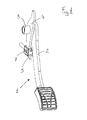
- figure 1 is a perspective view of the brake pedal of a motor-vehicle in which the coupling device for the cap of the servo brake is mounted in its operational position;
- figure 2 is an exploded view of the coupling device and of the end of the cap of the servo brake;
- figure 3 is a magnified perspective view of the coupling device already assembled and in which the cap has been inserted.
-
- With reference to the figures,
reference number 1 indicates a brake pedal of a motor-vehicle, with thearm 2 of which alever 4 is made rotatably integral by means of a bush, the lever being parallel to thearm 2 of the pedal. At thelower end 5 of said lever there is a through-pin 7 twoparts 8 of which protrude from both sides of the lever. A U-shapedclip 9, preferably made of harmonic steel, is applied on the lower end of the lever, the clip being provided with twoholes 10 on its two arms, adapted to get snap-coupled on the two protrudingparts 8 of thepin 7. The shape of thelower end 5 is such that the clip, once applied on theprotruding parts 8 of the pin cannot rotate on them more than 5-10 degrees, so that it is easier to mount it in the correct position. The arms of the clip are provided on both sides with a protrudinglimiting edge 12 while the twoholes 10 present alid 13 also protruding from the surface of the two arms. The two arms of the clip are provided also with twotongues 15 which serve as snap-couplers. - The head of the cap of the servo brake of the motor-vehicle presents a
terminal part 16 shaped as a double-fork 17 and made on a sheet-steel 18 which is U-shaped so that, following thelimiting edges 12, it can be inserted astride of theclip 9 in order to rest against theparts 8 protruding from theholes 10 on the clip, thelids 13 being placed between it and the clip in order to prevent wear. On the sheet-steel there are also twoholes 19 the shape of which is adapted to house the snap-tongues 15 and therefore hold the final part of the cap on theclip 9, articulated on thelower end 5 of thelever 4. - The appended drawings illustrate clearly that upon applying the
clip 9 on thelever 4, it will be enough to snap-insert thefinal part 16 on thetongues 15 of the clip to achieve a safe and stable coupling, being it easy to disengage the parts by simply pressing the twotongues 15, for instance by means of proper pliers.
Claims (5)
- A device adapted to couple the cap of the servo brake to the arm of the brake pedal of a motor-vehicle, characterised in that it consists of a lever (4) parallel to, and rotatably integral, by means of a bush (3), with the arm of the pedal (2), said lever being provided with a through-pin (7) at its lower end where a U-shaped clip (9) is engaged by means of two holes (10).
- A coupling device for the cap of the servo brake as claimed in claim 1, characterised in that the cap presents a final part (16) shaped as a double-fork (17) made on a U-shaped sheet-steel (18) adapted to be inserted astride of the clip (9).
- A coupling device for the cap of the servo brake as claimed in claim 1 and claim 2, characterised in that the part of the cap which is shaped as a double fork (17) rests against the parts (8) protruding from the holes (10) on the clip (9).
- A coupling device for the cap of the servo brake as claimed in the previous claims, characterised in that the holes (10) of the clip (9) are provided with a protruding lid (13) adapted to be placed between the double fork of the cap and the parts (8) of the through pin (7).
- A coupling device for the cap of the servo brake as claimed in the previous claims, characterised in that the clip is provided with tongues (15) to be snap-coupled with holes (19) made on the final part (16) of the cap which is shaped as a double fork.
Applications Claiming Priority (2)
| Application Number | Priority Date | Filing Date | Title |
|---|---|---|---|
| ITTO20040078 ITTO20040078U1 (en) | 2004-06-09 | 2004-06-09 | SPRING LOCKING DEVICE OF THE BRAKE BOOT OF A MOTOR VEHICLE. |
| ITTO20040078 | 2004-06-09 |
Publications (3)
| Publication Number | Publication Date |
|---|---|
| EP1604876A2 true EP1604876A2 (en) | 2005-12-14 |
| EP1604876A3 EP1604876A3 (en) | 2006-01-25 |
| EP1604876B1 EP1604876B1 (en) | 2007-06-06 |
Family
ID=35311079
Family Applications (1)
| Application Number | Title | Priority Date | Filing Date |
|---|---|---|---|
| EP20050007272 Active EP1604876B1 (en) | 2004-06-09 | 2005-04-04 | Clip coupling device for the cap of the servo brake of a motor-vehicle |
Country Status (3)
| Country | Link |
|---|---|
| EP (1) | EP1604876B1 (en) |
| DE (1) | DE602005001296T2 (en) |
| IT (1) | ITTO20040078U1 (en) |
Cited By (4)
| Publication number | Priority date | Publication date | Assignee | Title |
|---|---|---|---|---|
| FR2906323A1 (en) * | 2006-09-22 | 2008-03-28 | Peugeot Citroen Automobiles Sa | Lever i.e. brake pedal, and yoke joint connecting device for motor vehicle, has securing unit fixed on free end of axle and on lever when axle is positioned on holes, where axle has other end with shoulder that contacts with one branch |
| FR2906324A1 (en) * | 2006-09-22 | 2008-03-28 | Peugeot Citroen Automobiles Sa | Lever i.e. brake pedal, and yoke joint connecting device for motor vehicle, has extension of lever extending until bottom of yoke joint of control rod when articulation axle is not positioned and do not exert effort on lever |
| ES2324384A1 (en) * | 2008-02-04 | 2009-08-05 | Batz, S.Coop. | Pedal for motor vehicles (Machine-translation by Google Translate, not legally binding) |
| CN108584304A (en) * | 2018-05-20 | 2018-09-28 | 上海力格郎环保科技有限公司 | A kind of decline assembly in automatic transmission lowering means |
Citations (2)
| Publication number | Priority date | Publication date | Assignee | Title |
|---|---|---|---|---|
| US20020088300A1 (en) * | 2000-05-01 | 2002-07-11 | James Allen | Adjustable brake, clutch and accelerator pedals |
| EP1440857A1 (en) * | 2003-01-15 | 2004-07-28 | S.I.V. S.p.A. | A device for engaging the push-rod of the power brake to the brake pedal of a motor vehicle |
-
2004
- 2004-06-09 IT ITTO20040078 patent/ITTO20040078U1/en unknown
-
2005
- 2005-04-04 DE DE200560001296 patent/DE602005001296T2/en active Active
- 2005-04-04 EP EP20050007272 patent/EP1604876B1/en active Active
Patent Citations (2)
| Publication number | Priority date | Publication date | Assignee | Title |
|---|---|---|---|---|
| US20020088300A1 (en) * | 2000-05-01 | 2002-07-11 | James Allen | Adjustable brake, clutch and accelerator pedals |
| EP1440857A1 (en) * | 2003-01-15 | 2004-07-28 | S.I.V. S.p.A. | A device for engaging the push-rod of the power brake to the brake pedal of a motor vehicle |
Cited By (4)
| Publication number | Priority date | Publication date | Assignee | Title |
|---|---|---|---|---|
| FR2906323A1 (en) * | 2006-09-22 | 2008-03-28 | Peugeot Citroen Automobiles Sa | Lever i.e. brake pedal, and yoke joint connecting device for motor vehicle, has securing unit fixed on free end of axle and on lever when axle is positioned on holes, where axle has other end with shoulder that contacts with one branch |
| FR2906324A1 (en) * | 2006-09-22 | 2008-03-28 | Peugeot Citroen Automobiles Sa | Lever i.e. brake pedal, and yoke joint connecting device for motor vehicle, has extension of lever extending until bottom of yoke joint of control rod when articulation axle is not positioned and do not exert effort on lever |
| ES2324384A1 (en) * | 2008-02-04 | 2009-08-05 | Batz, S.Coop. | Pedal for motor vehicles (Machine-translation by Google Translate, not legally binding) |
| CN108584304A (en) * | 2018-05-20 | 2018-09-28 | 上海力格郎环保科技有限公司 | A kind of decline assembly in automatic transmission lowering means |
Also Published As
| Publication number | Publication date |
|---|---|
| ITTO20040078U1 (en) | 2004-09-09 |
| EP1604876A3 (en) | 2006-01-25 |
| EP1604876B1 (en) | 2007-06-06 |
| DE602005001296D1 (en) | 2007-07-19 |
| DE602005001296T2 (en) | 2008-01-31 |
Similar Documents
| Publication | Publication Date | Title |
|---|---|---|
| JP6985475B2 (en) | Systems and methods for mountable electronic device holders | |
| US7979950B2 (en) | Windscreen wiper device | |
| US6809257B2 (en) | Capped clip for pipe, electric cable or the like | |
| US20170284433A1 (en) | Mounting assembly | |
| EP1604876B1 (en) | Clip coupling device for the cap of the servo brake of a motor-vehicle | |
| US20090184550A1 (en) | Child vehicle seat | |
| US8474348B2 (en) | Pedal assembly for electronic braking system | |
| JPH04101882U (en) | mounting holder | |
| WO2007148167A3 (en) | An outer door handle for automotive vehicles | |
| US8505694B2 (en) | Link unit of brake assembly for bicycles | |
| WO2006138437A3 (en) | Pedal assembly having a hysteresis mechanism | |
| JP2011523829A (en) | Device for supporting portable electronic device having fixing device provided with magnetic support member | |
| WO2003001069A1 (en) | Capped clip for pipe, electric cable or the like | |
| CN102625883B (en) | Improvements in and relating to connection systems | |
| WO2010022956A8 (en) | Pedal arrangement with a standing pedal pivoting about a horizontal axis | |
| US20050061587A1 (en) | Brake device having adjustable spring member | |
| US7387047B2 (en) | Electronic pedal device | |
| JP2007105470A (en) | Parking brake, especially for wheelchair | |
| WO2007049257A3 (en) | Vehicle clutch, particularly motorcycle clutch | |
| EP1440857A1 (en) | A device for engaging the push-rod of the power brake to the brake pedal of a motor vehicle | |
| WO2006100541A8 (en) | Tire slip model | |
| US4655628A (en) | Pivotal attachment means employing a spring clip | |
| EP2175149A1 (en) | Locking device of an operating rod to a pedal | |
| EP1433679A1 (en) | A device for engaging the brake pedal of a motor vehicle to the push-rod of the power brake | |
| WO2008048701A3 (en) | Method and brake assembly retention device with automatic operation |
Legal Events
| Date | Code | Title | Description |
|---|---|---|---|
| PUAI | Public reference made under article 153(3) epc to a published international application that has entered the european phase |
Free format text: ORIGINAL CODE: 0009012 |
|
| PUAL | Search report despatched |
Free format text: ORIGINAL CODE: 0009013 |
|
| AK | Designated contracting states |
Kind code of ref document: A2 Designated state(s): AT BE BG CH CY CZ DE DK EE ES FI FR GB GR HU IE IS IT LI LT LU MC NL PL PT RO SE SI SK TR |
|
| AX | Request for extension of the european patent |
Extension state: AL BA HR LV MK YU |
|
| AK | Designated contracting states |
Kind code of ref document: A3 Designated state(s): AT BE BG CH CY CZ DE DK EE ES FI FR GB GR HU IE IS IT LI LT LU MC NL PL PT RO SE SI SK TR |
|
| AX | Request for extension of the european patent |
Extension state: AL BA HR LV MK YU |
|
| 17P | Request for examination filed |
Effective date: 20060224 |
|
| GRAP | Despatch of communication of intention to grant a patent |
Free format text: ORIGINAL CODE: EPIDOSNIGR1 |
|
| GRAS | Grant fee paid |
Free format text: ORIGINAL CODE: EPIDOSNIGR3 |
|
| AKX | Designation fees paid |
Designated state(s): DE FR GB IT |
|
| GRAA | (expected) grant |
Free format text: ORIGINAL CODE: 0009210 |
|
| AK | Designated contracting states |
Kind code of ref document: B1 Designated state(s): DE FR GB IT |
|
| REG | Reference to a national code |
Ref country code: GB Ref legal event code: FG4D |
|
| REF | Corresponds to: |
Ref document number: 602005001296 Country of ref document: DE Date of ref document: 20070719 Kind code of ref document: P |
|
| RAP2 | Party data changed (patent owner data changed or rights of a patent transferred) |
Owner name: SISTEMI COMANDI MECCANICI S.C.M. S.P.A. |
|
| ET | Fr: translation filed | ||
| PLBE | No opposition filed within time limit |
Free format text: ORIGINAL CODE: 0009261 |
|
| STAA | Information on the status of an ep patent application or granted ep patent |
Free format text: STATUS: NO OPPOSITION FILED WITHIN TIME LIMIT |
|
| 26N | No opposition filed |
Effective date: 20080307 |
|
| PGFP | Annual fee paid to national office [announced via postgrant information from national office to epo] |
Ref country code: GB Payment date: 20100329 Year of fee payment: 6 |
|
| PGFP | Annual fee paid to national office [announced via postgrant information from national office to epo] |
Ref country code: FR Payment date: 20100506 Year of fee payment: 6 |
|
| PGFP | Annual fee paid to national office [announced via postgrant information from national office to epo] |
Ref country code: DE Payment date: 20100407 Year of fee payment: 6 |
|
| PG25 | Lapsed in a contracting state [announced via postgrant information from national office to epo] |
Ref country code: IT Free format text: LAPSE BECAUSE OF NON-PAYMENT OF DUE FEES Effective date: 20090404 |
|
| PGFP | Annual fee paid to national office [announced via postgrant information from national office to epo] |
Ref country code: IT Payment date: 20100407 Year of fee payment: 6 |
|
| PGRI | Patent reinstated in contracting state [announced from national office to epo] |
Ref country code: IT Effective date: 20110616 |
|
| GBPC | Gb: european patent ceased through non-payment of renewal fee |
Effective date: 20110404 |
|
| REG | Reference to a national code |
Ref country code: FR Ref legal event code: ST Effective date: 20111230 |
|
| PG25 | Lapsed in a contracting state [announced via postgrant information from national office to epo] |
Ref country code: FR Free format text: LAPSE BECAUSE OF NON-PAYMENT OF DUE FEES Effective date: 20110502 Ref country code: DE Free format text: LAPSE BECAUSE OF NON-PAYMENT OF DUE FEES Effective date: 20111101 |
|
| REG | Reference to a national code |
Ref country code: DE Ref legal event code: R119 Ref document number: 602005001296 Country of ref document: DE Effective date: 20111101 |
|
| PG25 | Lapsed in a contracting state [announced via postgrant information from national office to epo] |
Ref country code: GB Free format text: LAPSE BECAUSE OF NON-PAYMENT OF DUE FEES Effective date: 20110404 |
|
| PGRI | Patent reinstated in contracting state [announced from national office to epo] |
Ref country code: IT Effective date: 20110616 |