EP1604875A1 - Vorrichtung zum motorischen Bewegen eines Sicherheitsgurts im Kraftfahrzeug - Google Patents
Vorrichtung zum motorischen Bewegen eines Sicherheitsgurts im Kraftfahrzeug Download PDFInfo
- Publication number
- EP1604875A1 EP1604875A1 EP05104939A EP05104939A EP1604875A1 EP 1604875 A1 EP1604875 A1 EP 1604875A1 EP 05104939 A EP05104939 A EP 05104939A EP 05104939 A EP05104939 A EP 05104939A EP 1604875 A1 EP1604875 A1 EP 1604875A1
- Authority
- EP
- European Patent Office
- Prior art keywords
- rack
- guide element
- output pinion
- transmission housing
- transmission
- Prior art date
- Legal status (The legal status is an assumption and is not a legal conclusion. Google has not performed a legal analysis and makes no representation as to the accuracy of the status listed.)
- Granted
Links
- 230000005540 biological transmission Effects 0.000 claims abstract description 35
- 238000001746 injection moulding Methods 0.000 claims abstract description 4
- 238000001514 detection method Methods 0.000 claims description 5
- 238000000034 method Methods 0.000 abstract 1
- 238000004519 manufacturing process Methods 0.000 description 5
- 238000013016 damping Methods 0.000 description 3
- 230000000903 blocking effect Effects 0.000 description 2
- 238000011161 development Methods 0.000 description 2
- 230000018109 developmental process Effects 0.000 description 2
- 230000010354 integration Effects 0.000 description 2
- 239000002184 metal Substances 0.000 description 2
- 238000000926 separation method Methods 0.000 description 2
- 238000005452 bending Methods 0.000 description 1
- 230000001419 dependent effect Effects 0.000 description 1
- 230000002349 favourable effect Effects 0.000 description 1
- 239000000463 material Substances 0.000 description 1
- 238000000465 moulding Methods 0.000 description 1
- 230000002093 peripheral effect Effects 0.000 description 1
Images


Classifications
-
- B—PERFORMING OPERATIONS; TRANSPORTING
- B60—VEHICLES IN GENERAL
- B60R—VEHICLES, VEHICLE FITTINGS, OR VEHICLE PARTS, NOT OTHERWISE PROVIDED FOR
- B60R22/00—Safety belts or body harnesses in vehicles
- B60R22/02—Semi-passive restraint systems, e.g. systems applied or removed automatically but not both ; Manual restraint systems
- B60R22/03—Means for presenting the belt or part thereof to the wearer, e.g. foot-operated
Definitions
- the invention relates to a device for motorized adjustment of a Safety belts in motor vehicles according to the preamble of independent claim 1.
- Such a seat belt provider system is known from EP 0 542 773 B 1 become, in which an electric motor drive unit by means of a driven pinion a rack in a guide sleeve shifts in the longitudinal direction. It extends the guide sleeve substantially over the entire length of the rack and is attached directly to the body.
- the guide sleeve is in such an embodiment in usually designed as a metal bending stamped part to which a mounting flange for Connection to the body is arranged.
- the electric drive unit will then fastened with fasteners also on the mounting flange such that the Output pinion engages the rack.
- Such a device has a relatively high Weight up and is costly to manufacture.
- the erfmdungsdorfe device for motorized movement of a seat belt with The characterizing features of independent claim 1 has the advantage that by integrating the guide element of the rack into the transmission housing electric drive unit both the separate production of the guide rail, as well the mounting flange is eliminated. Moreover, due to the integration of the Guide element in the transmission housing of the mounting step for fastening the electric drive unit on the mounting flange or on the guide element. By the manufacture of the transmission housing with the guide element as a component, the Axial distance between the rack and the output element made more accurate which reduces wear.
- the rack can be pushed in both directions.
- This can the guide element are formed relatively short, whereby the material requirements - and thus weight - and processing costs are significantly reduced.
- the length of the guide element for example, approximately the length of Transmission housing, as determined by the shorter sliding surface of the guide element smoother, more comfortable grinding noise between the rack and the Gearbox.
- you get a very compact built Gurtbringer the due to the open at both ends guide rail a body-fixed stop can use.
- the transmission housing consists of a base body and a gear cover whose separation surface is substantially transverse to the axis of the Output pinion is arranged.
- the guide element can in this case both in the Base body as well as integrated in the lid or in the parting plane.
- the belt feeder has a position detection on, in which the position of the rack counted by means of the adjustment Pulses is detected.
- a position detection on, in which the position of the rack counted by means of the adjustment Pulses is detected.
- the free end of the rack is driven against a body-fixed stop, until the electric motor comes to a standstill.
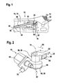
- Fig. 1 is a device 10 for the motorized movement of a safety belt 12th shown, which is installed in a side wall 14 of a body 15, as they For example, in a coupe, which has doors only in the front seats, is used.
- the device 10 has an electric drive unit 16 with a Electric motor 18 and arranged in a transmission housing 20 transmission 22.
- the electric drive unit 16 is fixedly mounted on the side wall 14.
- At the Gear housing 20 is an integral part of a guide member 24 for a Rack 26 integrally formed, which like the drive unit 16 in a molding 28 of the Side wall 14 is arranged.
- a Triangle 32 is arranged, through which the safety belt 12 is passed.
- the device 10 moves the belt 12 automatically from behind to the driver on the driver's seat, so that this can easily reach the belt 12.
- a further electric drive unit 16 is shown enlarged, wherein the electric motor 18 has a pole pot 40, which by means of connecting elements 42, for example, screws 42 is fixedly connected to the transmission housing 20.
- the Electric motor 18 is connected via a arranged on an armature shaft 46 screw 48 with a worm wheel 50 operatively connected, as shown in Fig. 5 in more detail.
- the Worm wheel 50 in turn is rigidly connected to an output gear 52, which with its toothing 54 engages in the rack 26, not shown.
- the Gear housing 20 has in the exemplary embodiment a base body 56 which both the armature shaft 46 and the worm wheel 50 and the output pinion 52 encloses.
- the gear housing 20 further includes a gear cover 58 to complete the worm wheel 50, with a separation plane 68 between the gear cover 58 and the main body 56 approximately perpendicular to a Axle 70 of the drive pinion 52 and the worm wheel 50 is arranged.
- the Output pinion 52 is here completely within the transmission housing 20, for example, mounted on a arranged in the transmission housing 20 shaft.
- the Transmission housing 20 is made of plastic, preferably by injection molding produced.
- Fig. 3 is on the guide member 24 as a position detecting device 72 a Micro switch 74 disposed in the corresponding switching notches 75 of the rack 26th attacks.
- the micro switch 74 is as well as a plug contact 76 on the electric motor 18 with not shown electrical connections 78 connected.
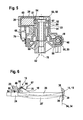
- Fig. 4 shows another embodiment of a Gurtbringers 10 with an im Guide element 24 arranged rack 26.
- the rack 26 protrudes from the two Openings 66, wherein at the front end 30 of the rack, the triangle 32 for the belt 12 is arranged and the rear end 36 is movable against a stop 38.
- the drive pinion 52 which is not visible in more detail engages with its toothing 54 in the teeth 27 the rack 26, wherein the distance between the output gear 52 and the Rack 26 formed by the one-piece with the transmission housing 20 Guide element 24 is fixed.
- the parting plane 68 between the lid 58 and the main body 56 of the gear housing 20 is in this embodiment between the worm wheel 50 and the driven pinion 52.
- the two housing parts 56, 58 are connected by connecting means 59 firmly together, so that with the finished Assembly of the gear housing 20 and the rack 26 frictionally with the Electric motor 18 is connected.
- the device 10 is in this case by means of a body-fixed bolt 80, which has a through hole 82 of the transmission housing 20th penetrates, connected to the side wall 14. For the axial fixation of the device 10 this is fixed with a securing element 84 on the bolt 80. Since that Gear housing 20 is rotatably mounted relative to the fixed bolt 80 is another provided body-fixed pin 86 which fixes the angular position of the device 10.
- Fig. 5 is an enlarged section through the transmission housing in Fig. 4 along the line V-V shown.
- the output element 52 is in this case in one piece with the worm wheel 50 formed, both a central through hole 82 for attachment by means of body-mounted bolt 80 have.
- the worm wheel 50 and the armature shaft 46 are essentially enclosed by a first gear housing part 56 and the Output pinion 52 from the second gear housing part 58 in the guide member 24th integrated, enclosed.
- the output gear 52 and the worm wheel 50 form a common component 51 which is completely mounted in the transmission housing 20.
- the gear housing 20 axial stop surfaces 87, 88, where the drive pinion 52nd and the worm wheel 50 abut for axial storage.
- Fig. 6 shows a schematic representation of the device 10 for moving the belt 12 in the operating state, wherein the rear end 36 of the rack 26 against a fixed Stop 38 of the body 15 is driven.
- the rack 26 is elastic formed, for example by the use of a corresponding plastic. Reached the free end 36 of the stop 38, the rack 26 can up to a bend sideways to a certain degree. In this case, the power requirement of the electric motor 18 increases until the electric motor 18 blocks. By the thereby caused Current increase, this blocking state can be detected as the reference position 94.
- the Position of the rack 26 is detected by means of a position detection 72, the preferably arranged on the armature shaft 46 pulse generator 95 and a with having this cooperating pulse counter 96, which with an electronic unit 97th are connected.
- the pulse counter 96th For example, set to zero, so that at any time by a reference run the zero position 34 can be readjusted.
- the electric motor 18 is turned off before the rear End 36 of the rack 26 reaches the fixed stop 38 of the body 15. there the number of pulses can be specified how far the electric motor 18 before Reaching the zero position 34 is to be switched off.
- the elastic side Dodge the rack 26 is the blocking moment when approaching the stop 38 damped in the transmission 22.
- a conventional belt feeder 10 is shown as the prior art.
- the drive unit 16 is screwed to a mounting flange 100, which in turn is attached to the guide member 24 of the rack 26.
- the guide element 24 this extends essentially over the entire length of the rack 26.
- An an end of the guide member 24, a stop buffer 101 is arranged to a elastic damping when approaching the rear end 36 of the rack 26 against the To reach stop 38.
- the mounting flange 100 has receptacles 102 for Connecting elements 103, with which the belt feeder 10 on the body 15th is fastened.
- the mounting flange 100 on Guiding member 24 integrally formed, and then the transmission housing 20 so with the Attachment flange 100 connected to the output pinion 52, which in this case off the gear housing 20 projects into the teeth 27 of the rack 26 engages.
- the concrete design of the Transmission housing 20, the guide member 24, the transmission 22, the motor 18 and the Befest Trent be varied, it being essential to the invention that the Guide member 24 as a common component with the transmission housing 20th is trained.
- the position detection device 72 may be used, for example, as Ring magnet and Hall sensor be formed, optionally with a micro switch 74th can be waived.
- the invention also includes an adjusting device 10 without the Assembly of the rack 26 and can be analogously for similar linear Adjustment applications, especially in motor vehicles, are used.
Landscapes
- Engineering & Computer Science (AREA)
- Mechanical Engineering (AREA)
- Transmission Devices (AREA)
Abstract
Description
Claims (12)
- Vorrichtung (10) zum motorischen Bewegen eines Sicherheitsgurts (12) in einem Kraftfahrzeug, mit einem in einem Getriebegehäuse (20) angeordneten Getriebe (22), das ein Abtriebsritzel (52) aufweist, wobei das Abtriebsritzel (52) mit einer Zahnstange (26) kämmt, die in einem Führungselement (28) längsverschiebbar angeordnet ist,
dadurch gekennzeichnet, dass das Führungselement (28) integrativer Bestandteil des Getriebegehäuses (20) ist. - Vorrichtung (10) nach Anspruch 1, dadurch gekennzeichnet, dass das Getriebegehäuse (20) und das Führungselement (28) zusammen aus Kunststoff - insbesondere mittels Spritzgußverfahren - hergestellt sind.
- Vorrichtung (10) nach einem der Ansprüche 1 oder 2, dadurch gekennzeichnet, dass das Abtriebsritzel (52) vom Getriebegehäuse (20) und dem Führungselement (28) umschlossen ist.
- Vorrichtung (10) nach einem der vorhergehenden Ansprüche, dadurch gekennzeichnet, dass das Führungselement (28) in Längsrichtung (64) an beiden Enden Öffnungen (66) aufweist, aus denen jeweils die Zahnstange (26) ragt.
- Vorrichtung (10) nach einem der vorhergehenden Ansprüche, dadurch gekennzeichnet, dass das Führungselement (28) in Längsrichtung (64) eine Länge (62) aufweist, die wesentlich kürzer ist als die Zahnstange (26) - und insbesondere in etwa der Abmessung des Getriebegehäuses (20) entspricht.
- Vorrichtung (10) nach einem der vorhergehenden Ansprüche, dadurch gekennzeichnet, dass das Getriebegehäuse (20) einen Grundkörper (56) und einen Getriebedeckel (58) aufweist, die miteinander fest verbindbar sind, wobei das Führungselement (28) in den Grundkörper (56) und/oder den Getriebedeckel (58) integriert ist.
- Vorrichtung (10) nach einem der vorhergehenden Ansprüche, dadurch gekennzeichnet, dass das Abtriebsritzel (52) einteilig mit einem axial versetzt angeordneten Schneckenrad (50) ausgebildet ist, das von einer Schnecke (48) eines Elektromotors (18) angetrieben wird.
- Vorrichtung (10) nach einem der vorhergehenden Ansprüche, dadurch gekennzeichnet, dass das Getriebegehäuse (20) mindestens eine axiale Anlauffläche 87, 88) aufweist, an der sich das Abtriebsritzel (52) axial abstützt.
- Vorrichtung (10) nach einem der vorhergehenden Ansprüche, dadurch gekennzeichnet, dass die Zahnstange (26) elastisch ausgebildet ist und beim Anfahren eines freien Endes (36, 30) der Zahnstange (26) gegen einen karosseriefesten Anschlag (38) die Zahnstange (26) quer zur Längsrichtung (64) ausknickt.
- Vorrichtung (10) nach einem der vorhergehenden Ansprüche, gekennzeichnet durch eine Positionserfassungseinrichtung (72), die einen Impulsgeber (95) und einen Impulszähler (96) aufweist, wobei beim Anfahren des freien Endes (36, 30) der Zahnstange (26) gegen den karosseriefesten Anschlag (38) der Motorstrom des Elektromotors (18) ansteigt und/oder der Elektromotor (18) blockiert, wodurch eine Referenzposition (94) der Zahnstange (26) für die Positionserfassung erkannt wird.
- Vorrichtung (10) nach einem der vorhergehenden Ansprüche, dadurch gekennzeichnet, dass nach der Durchführung eines Referenzlaufs die Zahnstange (26) um eine vorgebbare Anzahl von Impulsen vor dem Erreichen des karosseriefesten Anschlags (38) gestoppt wird.
- Vorrichtung (10) nach einem der vorhergehenden Ansprüche, dadurch gekennzeichnet, dass der karoseriefeste Anschlag (38) ein elastisches Element (39) aufweist.
Applications Claiming Priority (2)
| Application Number | Priority Date | Filing Date | Title |
|---|---|---|---|
| DE102004028281 | 2004-06-11 | ||
| DE200410028281 DE102004028281A1 (de) | 2004-06-11 | 2004-06-11 | Vorrichtung zum motorischen Bewegen eines Sicherheitsgurts im Kraftfahrzeug |
Publications (2)
| Publication Number | Publication Date |
|---|---|
| EP1604875A1 true EP1604875A1 (de) | 2005-12-14 |
| EP1604875B1 EP1604875B1 (de) | 2008-09-03 |
Family
ID=34940095
Family Applications (1)
| Application Number | Title | Priority Date | Filing Date |
|---|---|---|---|
| EP20050104939 Expired - Lifetime EP1604875B1 (de) | 2004-06-11 | 2005-06-07 | Vorrichtung zum motorischen Bewegen eines Sicherheitsgurts im Kraftfahrzeug |
Country Status (2)
| Country | Link |
|---|---|
| EP (1) | EP1604875B1 (de) |
| DE (2) | DE102004028281A1 (de) |
Families Citing this family (1)
| Publication number | Priority date | Publication date | Assignee | Title |
|---|---|---|---|---|
| DE102017215319A1 (de) * | 2017-09-01 | 2019-03-07 | Joyson Safety Systems Germany Gmbh | Gurtstraffereinheit für einen Sicherheitsgurt eines Kraftfahrzeugs |
Citations (2)
| Publication number | Priority date | Publication date | Assignee | Title |
|---|---|---|---|---|
| US4175633A (en) * | 1977-03-25 | 1979-11-27 | Daimler-Benz Aktiengesellschaft | Installation for feeding the lock tongue and/or the belt band of a belt system |
| EP0542773B1 (de) * | 1990-08-09 | 1994-11-17 | Robert Bosch Gmbh | Vorrichtung zum motorischen bewegen eines sicherheitsgurts in einem kraftfahrzeug |
-
2004
- 2004-06-11 DE DE200410028281 patent/DE102004028281A1/de not_active Withdrawn
-
2005
- 2005-06-07 DE DE200550005236 patent/DE502005005236D1/de not_active Expired - Lifetime
- 2005-06-07 EP EP20050104939 patent/EP1604875B1/de not_active Expired - Lifetime
Patent Citations (2)
| Publication number | Priority date | Publication date | Assignee | Title |
|---|---|---|---|---|
| US4175633A (en) * | 1977-03-25 | 1979-11-27 | Daimler-Benz Aktiengesellschaft | Installation for feeding the lock tongue and/or the belt band of a belt system |
| EP0542773B1 (de) * | 1990-08-09 | 1994-11-17 | Robert Bosch Gmbh | Vorrichtung zum motorischen bewegen eines sicherheitsgurts in einem kraftfahrzeug |
Also Published As
| Publication number | Publication date |
|---|---|
| DE102004028281A1 (de) | 2005-12-29 |
| DE502005005236D1 (de) | 2008-10-16 |
| EP1604875B1 (de) | 2008-09-03 |
Similar Documents
| Publication | Publication Date | Title |
|---|---|---|
| EP2119589B1 (de) | Einrichtung für eine Sitzlängsverstellung, insbesondere innerhalb eines Kfz | |
| DE19861100B4 (de) | Spindel- oder Schneckenantrieb für Verstelleinrichtungen in Kraftfahrzeugen | |
| WO1999051456A1 (de) | Spindel- oder schneckenantrieb für verstelleinrichtungen in kraftfahrzeugen | |
| EP1090201B1 (de) | Elektromotorischer antrieb, insbesondere fensterheberantrieb für ein kraftfahrzeug | |
| DE4325996C2 (de) | Verstellvorrichtung für eine motorisch einstellbare Kopfstütze eines Kraftfahrzeugs | |
| EP1493634A1 (de) | Airbagmodul mit Gehäuse für die Aufnahme mindestens eines Gasgenerators und mindestens eines Gassacks | |
| DE19861273B4 (de) | Spindel- oder Schneckenantrieb für Verstelleinrichtungen in Kraftfahrzeugen | |
| EP2287428A2 (de) | Türflügelantriebsvorrichtung mit teleskopierendem Türflügel | |
| WO2007036389A1 (de) | Getriebe-antriebseinheit mit einem aufnahmemodul, insbesondere zum verstellen eines beweglichen teils im kraftfahrzeug | |
| EP2059995A1 (de) | Sitzverstellvorrichtung für einen fahrzeugsitz | |
| EP1046000B1 (de) | Vorrichtung zum bewegen eines teils, insbesondere in einem kraftfahrzeug, mit einem verstellmechanismus | |
| WO2016110310A1 (de) | Gurtschlossbringer | |
| EP1604875B1 (de) | Vorrichtung zum motorischen Bewegen eines Sicherheitsgurts im Kraftfahrzeug | |
| EP3575637B1 (de) | Kraftfahrzeug-antriebsanordnung | |
| DE102010002159B4 (de) | Vorrichtung zum Verbinden einer Antriebseinheit für eine Verstelleinrichtung eines Kraftfahrzeugsitzes mit der Festigkeitsstruktur des Kraftfahrzeugsitzes | |
| DE19861278B4 (de) | Spindel- oder Schneckenantrieb für Verstelleinrichtungen in Kraftfahrzeugen | |
| EP1330013A1 (de) | Linearer Spindel-Verstellantrieb, insbesondere Kraftfahrzeug-Sitzverstellantrieb | |
| EP1758770B1 (de) | Verstellvorrichtung zum motorischen bewegen eines sicherheitsgurts im kraftfahrzeug sowie eine befestigungsvorrichtung und ein verfahren zum befestigen der verstellvorrichtung | |
| DE102005062999B4 (de) | Elektromotorischer Möbelantrieb | |
| EP1544488B1 (de) | Getriebe-Antriebseinheit, insbesondere ein Fensterheberantrieb, mit einem Adapterelement | |
| DE102023200134A1 (de) | Sitzlängsverstellung für einen Fahrzeugsitz | |
| DE202005004545U1 (de) | Vorrichtung zur Lagerung eines Elektromotors | |
| DE102022211675A1 (de) | Getriebe-Antriebseinheit sowie eine Lenksäulen-Verstellvorrichtung zum Verstellen von beweglichen Teilen in einem Fahrzeug | |
| DE102021211319A1 (de) | Getriebe-Antriebseinheit, Verfahren zur Montage einer Getriebe-Antriebseinheit und Komfortantrieb mit einer Getriebe-Antriebseinheit | |
| DE102020105407A1 (de) | Getriebegehäuseeinheit mit eingespannter Anlaufscheibe |
Legal Events
| Date | Code | Title | Description |
|---|---|---|---|
| PUAI | Public reference made under article 153(3) epc to a published international application that has entered the european phase |
Free format text: ORIGINAL CODE: 0009012 |
|
| AK | Designated contracting states |
Kind code of ref document: A1 Designated state(s): AT BE BG CH CY CZ DE DK EE ES FI FR GB GR HU IE IS IT LI LT LU MC NL PL PT RO SE SI SK TR |
|
| AX | Request for extension of the european patent |
Extension state: AL BA HR LV MK YU |
|
| 17P | Request for examination filed |
Effective date: 20060614 |
|
| AKX | Designation fees paid |
Designated state(s): DE ES FR HU |
|
| 17Q | First examination report despatched |
Effective date: 20060926 |
|
| 17Q | First examination report despatched |
Effective date: 20060926 |
|
| GRAP | Despatch of communication of intention to grant a patent |
Free format text: ORIGINAL CODE: EPIDOSNIGR1 |
|
| GRAS | Grant fee paid |
Free format text: ORIGINAL CODE: EPIDOSNIGR3 |
|
| GRAA | (expected) grant |
Free format text: ORIGINAL CODE: 0009210 |
|
| AK | Designated contracting states |
Kind code of ref document: B1 Designated state(s): DE ES FR HU |
|
| REF | Corresponds to: |
Ref document number: 502005005236 Country of ref document: DE Date of ref document: 20081016 Kind code of ref document: P |
|
| PG25 | Lapsed in a contracting state [announced via postgrant information from national office to epo] |
Ref country code: ES Free format text: LAPSE BECAUSE OF FAILURE TO SUBMIT A TRANSLATION OF THE DESCRIPTION OR TO PAY THE FEE WITHIN THE PRESCRIBED TIME-LIMIT Effective date: 20081214 |
|
| PLBE | No opposition filed within time limit |
Free format text: ORIGINAL CODE: 0009261 |
|
| STAA | Information on the status of an ep patent application or granted ep patent |
Free format text: STATUS: NO OPPOSITION FILED WITHIN TIME LIMIT |
|
| 26N | No opposition filed |
Effective date: 20090604 |
|
| PG25 | Lapsed in a contracting state [announced via postgrant information from national office to epo] |
Ref country code: HU Free format text: LAPSE BECAUSE OF FAILURE TO SUBMIT A TRANSLATION OF THE DESCRIPTION OR TO PAY THE FEE WITHIN THE PRESCRIBED TIME-LIMIT Effective date: 20090304 |
|
| REG | Reference to a national code |
Ref country code: DE Ref legal event code: R084 Ref document number: 502005005236 Country of ref document: DE Effective date: 20111025 |
|
| PGFP | Annual fee paid to national office [announced via postgrant information from national office to epo] |
Ref country code: FR Payment date: 20140617 Year of fee payment: 10 |
|
| REG | Reference to a national code |
Ref country code: FR Ref legal event code: ST Effective date: 20160229 |
|
| PG25 | Lapsed in a contracting state [announced via postgrant information from national office to epo] |
Ref country code: FR Free format text: LAPSE BECAUSE OF NON-PAYMENT OF DUE FEES Effective date: 20150630 |
|
| PGFP | Annual fee paid to national office [announced via postgrant information from national office to epo] |
Ref country code: DE Payment date: 20180807 Year of fee payment: 14 |
|
| REG | Reference to a national code |
Ref country code: DE Ref legal event code: R119 Ref document number: 502005005236 Country of ref document: DE |
|
| PG25 | Lapsed in a contracting state [announced via postgrant information from national office to epo] |
Ref country code: DE Free format text: LAPSE BECAUSE OF NON-PAYMENT OF DUE FEES Effective date: 20200101 |