EP1604769B1 - Dissimilar material weld joint formed by joining iron type material and aluminium type material, and weld joining method - Google Patents
Dissimilar material weld joint formed by joining iron type material and aluminium type material, and weld joining method Download PDFInfo
- Publication number
- EP1604769B1 EP1604769B1 EP05012465A EP05012465A EP1604769B1 EP 1604769 B1 EP1604769 B1 EP 1604769B1 EP 05012465 A EP05012465 A EP 05012465A EP 05012465 A EP05012465 A EP 05012465A EP 1604769 B1 EP1604769 B1 EP 1604769B1
- Authority
- EP
- European Patent Office
- Prior art keywords
- aluminum
- weld
- welding
- type material
- voids
- Prior art date
- Legal status (The legal status is an assumption and is not a legal conclusion. Google has not performed a legal analysis and makes no representation as to the accuracy of the status listed.)
- Ceased
Links
Images



Classifications
-
- B—PERFORMING OPERATIONS; TRANSPORTING
- B23—MACHINE TOOLS; METAL-WORKING NOT OTHERWISE PROVIDED FOR
- B23K—SOLDERING OR UNSOLDERING; WELDING; CLADDING OR PLATING BY SOLDERING OR WELDING; CUTTING BY APPLYING HEAT LOCALLY, e.g. FLAME CUTTING; WORKING BY LASER BEAM
- B23K9/00—Arc welding or cutting
- B23K9/23—Arc welding or cutting taking account of the properties of the materials to be welded
- B23K9/232—Arc welding or cutting taking account of the properties of the materials to be welded of different metals
-
- B—PERFORMING OPERATIONS; TRANSPORTING
- B23—MACHINE TOOLS; METAL-WORKING NOT OTHERWISE PROVIDED FOR
- B23K—SOLDERING OR UNSOLDERING; WELDING; CLADDING OR PLATING BY SOLDERING OR WELDING; CUTTING BY APPLYING HEAT LOCALLY, e.g. FLAME CUTTING; WORKING BY LASER BEAM
- B23K26/00—Working by laser beam, e.g. welding, cutting or boring
- B23K26/20—Bonding
- B23K26/32—Bonding taking account of the properties of the material involved
-
- B—PERFORMING OPERATIONS; TRANSPORTING
- B23—MACHINE TOOLS; METAL-WORKING NOT OTHERWISE PROVIDED FOR
- B23K—SOLDERING OR UNSOLDERING; WELDING; CLADDING OR PLATING BY SOLDERING OR WELDING; CUTTING BY APPLYING HEAT LOCALLY, e.g. FLAME CUTTING; WORKING BY LASER BEAM
- B23K26/00—Working by laser beam, e.g. welding, cutting or boring
- B23K26/20—Bonding
- B23K26/32—Bonding taking account of the properties of the material involved
- B23K26/323—Bonding taking account of the properties of the material involved involving parts made of dissimilar metallic material
-
- B—PERFORMING OPERATIONS; TRANSPORTING
- B23—MACHINE TOOLS; METAL-WORKING NOT OTHERWISE PROVIDED FOR
- B23K—SOLDERING OR UNSOLDERING; WELDING; CLADDING OR PLATING BY SOLDERING OR WELDING; CUTTING BY APPLYING HEAT LOCALLY, e.g. FLAME CUTTING; WORKING BY LASER BEAM
- B23K33/00—Specially-profiled edge portions of workpieces for making soldering or welding connections; Filling the seams formed thereby
- B23K33/004—Filling of continuous seams
-
- B—PERFORMING OPERATIONS; TRANSPORTING
- B23—MACHINE TOOLS; METAL-WORKING NOT OTHERWISE PROVIDED FOR
- B23K—SOLDERING OR UNSOLDERING; WELDING; CLADDING OR PLATING BY SOLDERING OR WELDING; CUTTING BY APPLYING HEAT LOCALLY, e.g. FLAME CUTTING; WORKING BY LASER BEAM
- B23K2103/00—Materials to be soldered, welded or cut
- B23K2103/08—Non-ferrous metals or alloys
- B23K2103/10—Aluminium or alloys thereof
-
- B—PERFORMING OPERATIONS; TRANSPORTING
- B23—MACHINE TOOLS; METAL-WORKING NOT OTHERWISE PROVIDED FOR
- B23K—SOLDERING OR UNSOLDERING; WELDING; CLADDING OR PLATING BY SOLDERING OR WELDING; CUTTING BY APPLYING HEAT LOCALLY, e.g. FLAME CUTTING; WORKING BY LASER BEAM
- B23K2103/00—Materials to be soldered, welded or cut
- B23K2103/18—Dissimilar materials
-
- B—PERFORMING OPERATIONS; TRANSPORTING
- B23—MACHINE TOOLS; METAL-WORKING NOT OTHERWISE PROVIDED FOR
- B23K—SOLDERING OR UNSOLDERING; WELDING; CLADDING OR PLATING BY SOLDERING OR WELDING; CUTTING BY APPLYING HEAT LOCALLY, e.g. FLAME CUTTING; WORKING BY LASER BEAM
- B23K2103/00—Materials to be soldered, welded or cut
- B23K2103/18—Dissimilar materials
- B23K2103/20—Ferrous alloys and aluminium or alloys thereof
-
- B—PERFORMING OPERATIONS; TRANSPORTING
- B23—MACHINE TOOLS; METAL-WORKING NOT OTHERWISE PROVIDED FOR
- B23K—SOLDERING OR UNSOLDERING; WELDING; CLADDING OR PLATING BY SOLDERING OR WELDING; CUTTING BY APPLYING HEAT LOCALLY, e.g. FLAME CUTTING; WORKING BY LASER BEAM
- B23K2103/00—Materials to be soldered, welded or cut
- B23K2103/50—Inorganic materials other than metals or composite materials
-
- Y—GENERAL TAGGING OF NEW TECHNOLOGICAL DEVELOPMENTS; GENERAL TAGGING OF CROSS-SECTIONAL TECHNOLOGIES SPANNING OVER SEVERAL SECTIONS OF THE IPC; TECHNICAL SUBJECTS COVERED BY FORMER USPC CROSS-REFERENCE ART COLLECTIONS [XRACs] AND DIGESTS
- Y10—TECHNICAL SUBJECTS COVERED BY FORMER USPC
- Y10T—TECHNICAL SUBJECTS COVERED BY FORMER US CLASSIFICATION
- Y10T428/00—Stock material or miscellaneous articles
- Y10T428/12—All metal or with adjacent metals
- Y10T428/12347—Plural layers discontinuously bonded [e.g., spot-weld, mechanical fastener, etc.]
-
- Y—GENERAL TAGGING OF NEW TECHNOLOGICAL DEVELOPMENTS; GENERAL TAGGING OF CROSS-SECTIONAL TECHNOLOGIES SPANNING OVER SEVERAL SECTIONS OF THE IPC; TECHNICAL SUBJECTS COVERED BY FORMER USPC CROSS-REFERENCE ART COLLECTIONS [XRACs] AND DIGESTS
- Y10—TECHNICAL SUBJECTS COVERED BY FORMER USPC
- Y10T—TECHNICAL SUBJECTS COVERED BY FORMER US CLASSIFICATION
- Y10T428/00—Stock material or miscellaneous articles
- Y10T428/12—All metal or with adjacent metals
- Y10T428/12493—Composite; i.e., plural, adjacent, spatially distinct metal components [e.g., layers, joint, etc.]
- Y10T428/12736—Al-base component
- Y10T428/1275—Next to Group VIII or IB metal-base component
- Y10T428/12757—Fe
Definitions
- the present invention relates to a dissimilar material weld joint formed by joining an iron type material and an aluminum type material and a weld joining method, which dissimilar material weld joint is suitably applied to transport vehicles such as automobiles and railway vehicles, machine parts, structural members such as building structures, and the like and is particularly needed when structures for automobiles are fabricated.
- the methods of forming a dissimilar material joint by joining a steel material and an aluminum material as described in Patent Documents 1 to 8 are generally: applicable to the materials having relatively simple shapes, such as flat plates; but not applicable to members having complicated shapes because of the restrictions from the geometry of the members. As a consequence, the methods are only applicable to limited applications and thus inferior in versatility. Further, another problem is that, by the methods, since a weld is formed spotwise, a continuously extending weld cannot be obtained. Furthermore, another problem is that, since the methods require complicated processes, the stability of quality cannot be secured, the cost incurred in joining increases, and thus the methods lack in practicability. In addition, yet another problem is that the methods cannot be applied to an existing welding line, therefore new equipment has to be introduced if one of the methods is to be applied, and resultantly the equipment cost increases.
- a high joint strength can be secured by controlling the direction in which intermetallic compounds acting as an impediment to the securement of strength develop.
- the method is the one wherein a hole is formed beforehand on the side of a steel material to be joined, then the hole is filled with molten aluminum material, and thereby the steel material and an aluminum material are joined.
- Patent Document 9 JP-A No. 94162/2000
- Patent Document 2 JP-A No. 197846/1999
- Patent Document 3 JP-A No. 185040/1998
- Patent Document 4 JP-A No.
- Patent Document 5 JP-A No. 8056/1993
- Patent Document 6 JP-A No. 141755/1996
- Patent Document 7 JP-A No. 39558/1994
- Patent Document 8 JP-A No. 63762/1994
- Patent Document 9 JP-A No. 33865/2003
- Non-patent Document 1 WELDING JOURNAL, (1963), p. 302
- Non-patent Document 2 Light Metal Welding: Vol. 16 (1978), No. 12, p. 8 that showes in combination the features of the preamble of claim 1 and claim 4.
- Non-patent Documents 1 and 2 have been that, when a large number of holes are formed cyclically in proportion to the length of a joint and arc welding is applied continuously to form a weld line along the hole row, cracking occurs in the bead and rather the fatigue strength of the weld joint lowers.
- the reason is that brittle intermetallic compounds form inside the bead since the Fe type component in the steel material melts and mixes into the bead comprising an aluminum welding material.
- the MIG brazing method described in the aforementioned Patent Document 9 has fewer restrictions on application conditions and others and is excellent in versatility when a steel material and an aluminum material are joined.
- brittle intermetallic compounds such as Fe/Al type compounds are formed at the joint interface between a steel material and an aluminum material, and there has been still room for the improvement of joint strength.
- the object of the present invention is: to further improve the performance of a joint formed by the joining method using arc welding, as disclosed in the aforementioned Patent Document 9, which makes the welding procedure very easy and allows linear welding; and more specifically to establish a joining method using arc welding, which joining method allows a joint excellent in ductility to be formed stably while securing a high strength.
- the gist of a dissimilar material weld joint according to the present invention to attain the above object is a dissimilar material weld joint formed by joining an iron type material and an aluminum type material according to the claim 1.
- the arc welding method using an aluminum welding wire is applied to the weld joining.
- the lower end portion of the weld formed by filling the voids with the molten aluminum welding material melts in the surface layer of the aluminum type material exposed at the voids and the upper end portion thereof melts and is joined to the bead which comprises the aluminum welding material and is formed over the surface of the iron type material; and, when the thickness of the aluminum type material is defined as Ta, the maximum melt-in depth to which the weld melts in the surface layer of the aluminum type material as D, the average thickness of the weld bead on the weld line as Tb, and the circle-equivalent radius of the voids as R, the value D/Ta is not less than 0.10 and the value Tb/R is not less than 0.50.
- the weld joining method of a dissimilar material weld joint comprising an iron type material and an aluminum type material according to the present invention to attain the above object is a method of joining an iron type material and an aluminum type material to form a dissimilar material weld joint by arc welding according to the claim 4.
- the quantity of heat input Q (kj/cm) in arc welding is defined by the following expression and the thickness of the aluminum type material is defined as Ta (mm)
- welding is applied so as to satisfy the expression Ta/3.5 ⁇ Q ⁇ Ta/1.4 in the case of an AC power source or the expression Ta/1.5 ⁇ Q ⁇ Ta/0.7 in the case of a DC power source;
- Q kj / cm 60 s . / min . x Welding current
- Non-patent Documents 1 and 2 when the length of a joint or a joint line is long, it is necessary to form many holes in proportion to the length.
- the problem has been that, when arc welding is applied to form a weld line along the row of the many holes, cracking occurs in the bead comprising an aluminum welding material and rather the fatigue strength of the weld joint lowers. The reason is that brittle intermetallic compounds form inside the bead since the Fe type component in the steel material melts and mixes into the bead comprising the aluminum welding material.
- the present inventors have found that, by controlling in a prescribed range the ratio of the length (width) of an aluminum welding material with which the holes (the voids) are filled to the length (width) of an iron type material adjacent to the holes filled with the aluminum welding material along a weld line formed after joining, it becomes possible to inhibit to the utmost the iron type material from melting and mixing into the weld bead formed on the surface by the melting and solidification of the aluminum welding material. Thereby, it becomes possible to inhibit brittle Fe-Al type intermetallic compounds from forming inside the bead, thus to inhibit the bead surface from cracking, and to obtain a high joint strength even when the joint line of a joint is long.
- the maximum melt-in depth to which a weld formed by melting in the voids of an iron type material and filling the voids with a welding material melts in an aluminum type material is defined as D
- the average thickness of the weld bead formed on the surface of the iron type material by melting and being joined to the weld as Tb
- the thickness of the aluminum type material as Ta
- the circle-equivalent radius of the penetrating holes as R
- the present invention makes it possible to directly join an iron type material and an aluminum type material, which has heretofore been regarded as being difficult since brittle intermetallic compounds are formed. Thereby, the formed joint does not have defects such as cracking and a sound weld joint having higher joint strength and ductility can be obtained. Moreover, by adopting a joining method according to the present invention, it becomes possible to join an iron type material and an aluminum type material continuously in an efficient manner, and to easily produce the joint.
- Fig. 1A (the plan view) and Fig. 1B (the side view) show an embodiment of a dissimilar material weld joint stipulated in the present invention.
- the dissimilar material weld joint 1 is formed by laying the upper steel material (steel sheet) 2 on the lower aluminum material (aluminum alloy sheet) 3 and joining them by arc welding along the weld line 6.
- the reference numeral 5 is the weld bead formed on the surface of the weld by melting and solidifying an aluminum welding material supplied from an aluminum welding wire or the like.
- Fig. 1A shows the weld structure excluding the weld bead 5 formed on the upper side.
- the reference character 4a represents a plurality of round holes which are voids formed beforehand on the joining side of the steel material 1 at intervals along the weld line.
- the reference numeral 7 is the aluminum welding material supplied from an aluminum welding wire or the like and formed by melting and solidifying after the round holes 4a are filled therewith at the time of weld joining.
- L-Al represents the length along the weld line of the aluminum welding material (the width of the aluminum welding material), stipulated in the present invention, formed after joining by filling the round holes 4a with the aluminum welding material and solidifying it.
- L-Fe represents the length along the weld line of the steel material adjacent to the holes (of the length L-Al) (the interval between adjacent round holes 4a) stipulated in the present invention.
- the present invention stipulates that both the materials are weld joined so that the minimum value of the ratio (L-Al)/(L-Fe) of the length (L-Al) to the length (L-Fe), which are the lengths per 100 mm in length of the weld line 6 formed after joining (hereunder referred to as "P value" occasionally) is in the range from 0.5 to 7.
- P value the ratio of the ratio (L-Al)/(L-Fe) of the length (L-Al) to the length (L-Fe), which are the lengths per 100 mm in length of the weld line 6 formed after joining.
- the minimum value (the P value) is determined from among the ratios (L-Al)/(L-Fe) of the lengths (L-Al) to the adjacent lengths (L-Fe), which figures are obtained in the above range, and the minimum value P is controlled so as to be in the range from 0.5 to 7 as stated above.
- the portion of the weld line 6 used as the unit length 100 mm is arbitrarily selected from the actual weld line 6. Further, the weld line 6 may be either a straight line or a curved line.
- the P value is determined by measuring P values at plural portions of the unit length 100 mm selected arbitrarily on the weld line used as and averaging the measured P values.
- a P value the minimum value of (L-Al)/(L-Fe)
- the amount of the iron type material melting and mixing into the weld bead mainly composed of aluminum increases excessively. Thereby, brittle intermetallic compounds form in quantity and that leads to cracking in the weld bead.
- a P value exceeding 7 means that the length of a round hole 4a (a void of a steel material) and the length of the steel material portion (the non-void portion of the steel material) are close to each other (the interval between a round hole 4a and the next round hole 4a is too short).
- heat imposed to fill the round holes 4a (the voids) with molten aluminum material at the time of welding tends to accumulate at the steel material portions (non-void portions).
- the heat at the steel material portion (the non-void portion) is large and hence iron tends to melt into the aluminum molten metal that forms a bead.
- a P value less than 0.5 means that the length of the steel material portion (the non-void portion of the steel material) is longer than the length of a round hole 4a (a void of a steel material) (the interval between a round hole 4a and the next round hole 4a is too long).
- the temperature of the steel material portion (the non-void portion) to be subsequently welded rises undesirably as the welding proceeds. Thereby the same phenomenon as the case of a too large P value occurs as a result and the bead cracks likewise.
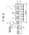
- Fig. 2 is a front view showing an embodiment of a weld joining method of a dissimilar material weld joint stipulated in the present invention.
- Fig. 2 shows the method of forming a dissimilar material joint by the arc welding method.
- the reference numeral 11 is a welding torch and the reference numeral 10 is an aluminum welding wire, and welding is carried out and the aluminum bead 5 is formed while the welding torch and the aluminum welding wire move along the portion formed by laying the upper steel material (steel sheet) 2 on the lower aluminum material (aluminum alloy sheet) 3 in the direction shown by the arrow in Fig. 2 (from the right side to the left side in Fig. 2 ).
- the reference character 4a represents a plurality of round holes, namely voids, formed beforehand on the joining side of the steel material 2 at intervals along the weld line.
- Fig. 2 shows the state wherein: the two round holes 4a on the left side are not yet filled with an aluminum welding material; and the round holes 4a formed on the right side thereof are filled with the aluminum welding material 7 formed by being supplied from an aluminum welding wire or the like, melting and solidifying while the welding torch passes through the round holes 4a.
- a P value which is the minimum value of the ratio (L-Al)/(L-Fe) of the length (L-Al) to the length (L-Fe) per 100 mm in length of the weld line 6 formed after joining is in the range from 0.5 to 7.
- an aluminum welding wire is used; a steel material (an iron type material) is placed on the upper side and an aluminum material (an aluminum type material) is placed on the lower side; and then arc welding is applied.
- any one of the above requirements is not satisfied, then it is impossible to melt and solidify an aluminum welding material and fill the round holes 4a formed in the steel material 2 with the aluminum welding material.
- an aluminum weld 7 is formed by filling the holes (voids) 4 of the steel material 2.
- the lower end of the aluminum weld 7 melts and is joined in the o state wherein the aluminum weld 7 melts into the surface layer of the aluminum material 3 exposed in the hole 4 and the portion where the aluminum weld 7 melts into the surface layer is formed from the inner lower circumference of the hole 4 to the maximum depth (the maximum melt-in depth of the melted portion is defined as D) at the center portion of the hole 4.
- the upper ends of the aluminum weld 7 melt into and are integrated in the weld bead 5 formed over the surface of the steel sheet 2 along the weld line.
- the distance from the upper face of the steel sheet 2 to the upper face of the weld bead 5 is called a bead thickness and the average thickness along the weld line 6 is expressed by Tb.
- the weld bead 5, the aluminum weld 7 and the melt-in portions are formed integrally with an aluminum welding material supplied by melting a welding wire.
- the ratio D/Ta is not less than 0.10 when the thickness of an aluminum material 3 is defined as Ta.
- the ratio D/Ta is preferably 0.10, or yet preferably 0.40.
- the ratio Tb/R is not less than 0.50.
- the lower limit of the ratio Tb/R is preferably 0.50, or yet preferably 0.70. Note that, when the melt-in portion increases, molten aluminum welding material penetrates through an aluminum material 3 and extends onto the bottom surface, and thus a weld bead 5 is not formed. For that reason, it is not specifically necessary to regulate the upper limit of the ratio D/Ta and it is enough if the lower limit of the ratio Tb/R is regulated.
- Fig. 4A the plan view
- Fig. 4B the side view
- the interval L1 between a round hole 4a and an adjacent round hole 4a determines the length L-Fe as a constituent element of a P value.
- the diameter (width) L2 of each round hole 4a determines the length L-Al as the other constituent element of a P value.
- the interval L1 between adjacent two round holes 4a and the diameter (width) L2 of each round hole 4a are set so that the P value is in the range from 0.5 to 7 after welding in accordance with the joint and the welding conditions.
- the shape of a void formed in a steel material is not limited to such a round hole 4a (a circular hole) but can arbitrarily be selected from among a round shape, a square shape, a polygonal shape, an indeterminate shape, and a combination thereof, including an elliptical shape 4b, a trapezoidal shape 4c, and a triangular shape 4d shown in Fig. 5 , as long as the shape can exhibit the effect of the present invention and can be formed easily.
- a shape having corners like a square shape for example, even if a void is filled with molten aluminum, there is the possibility that the corner portions become the sites of stress concentration and that lowers the strength and fatigue strength of a joint. From this point of view, a round shape, an elliptical shape, or the like having no corner portions and hardly causing stress concentration is desirable.
- any method can be adopted as long as voids of a steel material are filled and an aluminum welding material can be supplied to form a bead, and laser welding or the like may be adopted. Therefore no particular limitation is set, but the arc welding method is recommended in consideration of versatility.
- arc welding recommended from the viewpoint of versatility, it is desirable to control welding current so as not to be excessive during welding.
- the arc welding conditions desirable for the performance of the present invention are as follows.
- Arc welding conditions desirable for the performance of the present invention are as follows on the premise that the aforementioned regulation on the quantity of heat input is satisfied.
- an AC power source it is not less than 60 A, preferably not less than 70 A and not more than 100 A, preferably not more than 90 A.
- a DC power source it is not less than 60 A, preferably not less than 70 A and not more than 140 A, preferably not more than 130 A.
- an AC power source it is not less than 10 V, preferably not less than 11 V and not more than 15 V, preferably not more than 14 V.
- a DC power source it is not less than 13 V, preferably not less than 14 V and not more than 19 V, preferably not more than 18 V.
- an AC power source and a DC power source it is not less than 20 cm/min., preferably not less than 30 cm/min. and not more than 120 cm/min., preferably not more than 100 cm/min.
- a generally used gas including an Ar gas can arbitrarily be used.
- a gas flow rate a generally employed flow rate can be selected and no regulation is set.
- a steel material and an aluminum material can directly be joined and therefore, as long as a welding current, a welding voltage, a joint geometry and others are adequately selected, no particular restriction is imposed, the applicable range and versatility expand, and moreover there is the effect of enabling continuous joining. Then as stated above, a sound joining state can be secured with the minimum required amount of the molten (diluting) steel material in a weld metal such as a bead, brittle intermetallic compounds are hardly formed, and resultantly a high joint strength can be obtained.
- the material of a welding wire used in arc welding may arbitrarily be selected in accordance with a joint and welding conditions as long as the material is of an aluminum type that can fill the voids of a steel material and supply the aluminum welding material for forming a bead.
- a heretofore known Al-Si type wire or Al-Mg type wire can be used.
- various materials stipulated in JIS can be used.
- preferably used is A4043-WY, A4047-WY or the like as an Al-Si type wire or A5554-WY, A5356-WY, A5183-WY or the like as an Al-Mg type wire.
- a welding wire is not limited to those materials.
- An iron type material cited in the claims of the present invention means a steel material of an ordinary steel, a high tensile strength steel or the like.
- the kind or the shape of a steel material used for a joint is not particularly limited and a material having an arbitrary shape, such as a steel sheet, a shape, a steel pipe or the like, can be used, which is generally used for a structural member or is selected on the basis of application to a structural member.
- a hot-dip galvanized steel sheet produced by applying hot-dip galvanizing to such a steel sheet can also be used.
- the term "iron type material” is used in the claims of the present invention.
- An aluminum type material cited in the claims of the present invention means an aluminum material such as a pure aluminum type material or an aluminum alloy type material.
- the kind of alloy or the shape of an aluminum material used in the present invention is not particularly limited and a generally used sheet material, shape material, forged material, cast material or the like can arbitrarily be selected in accordance with the properties required as a structural member.
- the term "aluminum type material" is used in the claims of the present invention.
- the present invention is hereunder explained more specifically on the basis of examples.
- the present invention is naturally not limited to the after-mentioned examples, any arbitrary modification can be accepted as long as it is in conformity with the aforementioned or after-mentioned tenor of the present invention, and those modifications are included in the technological scope of the present invention.
- the present inventors laid a steel sheet (extending from a mild steel sheet SPCE to a high tensile strength steel sheet of up to 980 MPa) in which voids (holes) were formed according to the present invention on an aluminum alloy sheet (A5182), subjected them to lap weld tests using various kinds of aluminum welding wires, thus produced a dissimilar material weld joint, and then evaluated it.
- Table 1 shown are the conditions (the grade and the thickness) of the steel sheets and the aluminum alloy sheets used in the present weld tests, the welding wire condition (the grade), the welding conditions (the electric current, the voltage and the welding speed), the void conditions (the shape and the parameter P value), the evaluation results (existence of bead cracking and the tensile strength and elongation of the joints), and others.
- an AC power source was used for all the welding.
- a round shape was adopted as the shape of the voids formed in all the steel type materials and the diameter thereof was used as the parameter of the size.
- sectional area of a joint was defined by the sectional area of an aluminum alloy sheet in the sheet thickness direction.
- the bead cracking was evaluated by inspecting the existence of cracking at a weld joint through visual inspection and a penetrant test;
- the welding condition parameter P values were in the range from 0.5 to 7 and high joint strengths of 120 MPa or more were stably obtained. Further, in those cases, the elongations were not less than 4% and the ductility of the joints was also high. In conclusion, in the cases of the invention examples 5 to 14, obtained could be sound joints that had not only high strength and ductility but also excellent joint strength and moreover no cracking at the weld joints. On the other hand, in the cases of the comparative examples 1 to 3, the P values exceeded the upper limit 7. As a result, though joint strengths of 100 MPa or more were obtained, bead cracking occurred and those were not sound weld joints.
- the present inventors produced weld joints by joining steel sheets ("GA” in the column “Type” meant a hot-dip galvanized steel sheet) and aluminum alloy sheets shown in Table 2 below under various heat input conditions through arc welding using an AC power source and various kinds of aluminum welding wires.
- steel sheets round-shaped voids of the diameters (2R, R meant a circle-equivalent radius) shown in Table 2 were formed beforehand at the intervals (the lengths of the non-void portions) shown in Table 2.
- an Ar gas flow rate of 20 to 25 l./min.
- the angle of the welding torch was set at 80°.
- the Mg contents in the aluminum welding wires used here were as follows; 0.05% or less for A4043-WY, 4.3 to 5.2% for A5183-WY, 4.5 to 5.5% for A5356-WY, and 2.4 to 3.2% for A5554-WY
- the produced weld joints were visually inspected to judge the existence of bead cracking and also the joint strength thereof was measured.
- the bead cracking was evaluated in the same manner as shown in Example 1.
- the joint strength was determined by counting the number of rivets (aluminum welds) on the fractured pieces of each specimen (test piece) after subjected to a tensile test, calculating the bonded area of each specimen, and then dividing the breaking load by the calculated value.
- the results are shown in Table 3.
- the materials used for joining are also shown in Table 3.
- the present inventors produced weld joints by joining steel sheets ("GA” in the column “Type” meant a hot-dip galvanized steel sheet) and aluminum sheets shown in Table 4 below under various heat input conditions through arc welding using a DC power source and various kinds of aluminum welding wires.
- G steel sheets
- R round-shaped voids of the diameters (2R, R meant a circle-equivalent radius) shown in Table 4 were formed beforehand at the intervals (the lengths of the non-void portions) shown in Table 4.
- an Ar gas flow rate of 20 to 25 l./min.
- the angle of the welding torch was set at 80°.
- the present invention makes it possible to obtain a sound dissimilar material weld joint not only having a high strength, a high ductility and thus an excellent joint strength but also yielding no cracking.
- the present invention makes it possible to provide a joining method that makes use of arc welding, facilitates the welding procedure, and allows linear welding to be applied.
- the present invention is useful in the field of a dissimilar material weld joint formed by joining a steel material and an aluminum material.
Landscapes
- Engineering & Computer Science (AREA)
- Physics & Mathematics (AREA)
- Optics & Photonics (AREA)
- Mechanical Engineering (AREA)
- Plasma & Fusion (AREA)
- Chemical & Material Sciences (AREA)
- Materials Engineering (AREA)
- Arc Welding In General (AREA)
- Butt Welding And Welding Of Specific Article (AREA)
Description
- The present invention relates to a dissimilar material weld joint formed by joining an iron type material and an aluminum type material and a weld joining method, which dissimilar material weld joint is suitably applied to transport vehicles such as automobiles and railway vehicles, machine parts, structural members such as building structures, and the like and is particularly needed when structures for automobiles are fabricated.
- If members comprising different kinds of metals (dissimilar material joints) of an iron type material (hereunder referred to simply as "a steel material") and an aluminum type material (a generic name of pure aluminum and aluminum alloys, and hereunder referred to simply as "an aluminum material") can be joined, it remarkably contributes to weight reduction and the like. However, when a steel material and an aluminum material are weld joined, brittle intermetallic compounds are likely to form at the weld and therefore it has been very difficult to obtain a reliable weld having a high strength (joint strength). Joining with bolts, rivets or the like has heretofore been applied to the joining of dissimilar materials (members of different metals) accordingly, but such joints have problems in reliability, airtightness, cost and others.
- In this light, many studies have heretofore been done with regard to the joining method of a dissimilar material joint. Then, the following joining methods have been proposed for example;
a method of joining dissimilar materials by vacuum roll cladding (refer to Patent Document 1),
a method of seam-welding dissimilar materials while interposing a two-layered clad material comprising an iron type material layer and an aluminum alloy layer which have been prepared beforehand (refer to Patent Document 2),
a method of joining dissimilar materials by applying pressure bonding at a high temperature (refer to Patent Document 3),
a method of joining dissimilar materials by interposing beforehand a Ti alloy on the joint surface thereof and then applying HIP treatment (refer toPatent Documents 4 and 5),
a method of joining dissimilar materials by friction welding (refer to Patent Document 6),
a method of joining dissimilar materials by plating a steel material on the surface facing aluminum with aluminum alloy or interposing a two-layered clad metal comprising an steel layer and an aluminum alloy layer prepared in advance, and then applying resistance welding (refer toPatent Documents 7 and 8), and
a method of joining dissimilar materials by arc-welding a steel material and an aluminum material (refer to Non-patent Documents 1 and 2). - The above prior arts however have the following problems.
- The methods of forming a dissimilar material joint by joining a steel material and an aluminum material as described in Patent Documents 1 to 8 are generally: applicable to the materials having relatively simple shapes, such as flat plates; but not applicable to members having complicated shapes because of the restrictions from the geometry of the members. As a consequence, the methods are only applicable to limited applications and thus inferior in versatility. Further, another problem is that, by the methods, since a weld is formed spotwise, a continuously extending weld cannot be obtained. Furthermore, another problem is that, since the methods require complicated processes, the stability of quality cannot be secured, the cost incurred in joining increases, and thus the methods lack in practicability. In addition, yet another problem is that the methods cannot be applied to an existing welding line, therefore new equipment has to be introduced if one of the methods is to be applied, and resultantly the equipment cost increases.
- In contrast, in the case of the method of joining a steel material and an aluminum material by arc welding as described in the
aforementioned Non-patent Documents 1 and 2, a high joint strength can be secured by controlling the direction in which intermetallic compounds acting as an impediment to the securement of strength develop. The method is the one wherein a hole is formed beforehand on the side of a steel material to be joined, then the hole is filled with molten aluminum material, and thereby the steel material and an aluminum material are joined. - One of the basic reasons why such various methods as described above are proposed in the case of the joining of a steel material and an aluminum material is that, when the steel material and the aluminum material melt and are directly joined to each other, brittle intermetallic compounds form at the weld and thus cracking is likely to occur. In that sense, when a steel material and an aluminum material are directly joined including the case of joining them with a welding wire, it becomes extremely important to adopt any one of the following means; 1) how to secure the ductility of the molten metal portion by inhibiting to the utmost iron in the steel material and aluminum in the aluminum material from melting and mixing, 2) how to avoid forming a brittle intermetallic compound layer in the vicinity of the interface between the steel material and the aluminum material, or 3) how to design the shape of a joint that does not hinder the mechanical properties thereof even if brittle intermetallic compounds are formed at the joint interface between the steel material and the aluminum material.
- Then from that point of view, the present inventors have variously studied with the aim of establishing a joining method capable of securing a sound weld joint while resolving the problems described in the above items 1) and 2) as much as possible. As a result, the present inventors have found that, when the method is adopted of directly joining a steel material and an aluminum material by the MIG brazing method, a highly reliable weld joint can be obtained while avoiding various problems pointed out in the above prior arts (refer to Patent Document 9).
[Patent Document 1]JP-A No. 94162/2000
[Patent Document 2]JP-A No. 197846/1999
[Patent Document 3]JP-A No. 185040/1998
[Patent Document 4]JP-A No. 198458/1994
[Patent Document 5]JP-A No. 8056/1993
[Patent Document 6]JP-A No. 141755/1996
[Patent Document 7]JP-A No. 39558/1994
[Patent Document 8]JP-A No. 63762/1994
[Patent Document 9]JP-A No. 33865/2003
[Non-patent Document 1] WELDING JOURNAL, (1963), p. 302 [Non-patent Document 2] Light Metal Welding: Vol. 16 (1978), No. 12, p. 8 that showes in combination the features of the preamble of claim 1 andclaim 4. - Nevertheless, the problem of the aforementioned
Non-patent Documents 1 and 2 has been that, when a large number of holes are formed cyclically in proportion to the length of a joint and arc welding is applied continuously to form a weld line along the hole row, cracking occurs in the bead and rather the fatigue strength of the weld joint lowers. The reason is that brittle intermetallic compounds form inside the bead since the Fe type component in the steel material melts and mixes into the bead comprising an aluminum welding material. Meanwhile, the MIG brazing method described in the aforementioned Patent Document 9 has fewer restrictions on application conditions and others and is excellent in versatility when a steel material and an aluminum material are joined. However, it really happens that brittle intermetallic compounds such as Fe/Al type compounds are formed at the joint interface between a steel material and an aluminum material, and there has been still room for the improvement of joint strength. - In this light, the object of the present invention is: to further improve the performance of a joint formed by the joining method using arc welding, as disclosed in the aforementioned Patent Document 9, which makes the welding procedure very easy and allows linear welding; and more specifically to establish a joining method using arc welding, which joining method allows a joint excellent in ductility to be formed stably while securing a high strength.
- The gist of a dissimilar material weld joint according to the present invention to attain the above object is a dissimilar material weld joint formed by joining an iron type material and an aluminum type material according to the claim 1.
- It is preferable that the arc welding method using an aluminum welding wire is applied to the weld joining.
- It is preferable that: the lower end portion of the weld formed by filling the voids with the molten aluminum welding material melts in the surface layer of the aluminum type material exposed at the voids and the upper end portion thereof melts and is joined to the bead which comprises the aluminum welding material and is formed over the surface of the iron type material; and, when the thickness of the aluminum type material is defined as Ta, the maximum melt-in depth to which the weld melts in the surface layer of the aluminum type material as D, the average thickness of the weld bead on the weld line as Tb, and the circle-equivalent radius of the voids as R, the value D/Ta is not less than 0.10 and the value Tb/R is not less than 0.50.
- Further, the weld joining method of a dissimilar material weld joint comprising an iron type material and an aluminum type material according to the present invention to attain the above object is a method of joining an iron type material and an aluminum type material to form a dissimilar material weld joint by arc welding according to the
claim 4. - In addition, in the above welding conditions, it is preferable that, when the quantity of heat input Q (kj/cm) in arc welding is defined by the following expression and the thickness of the aluminum type material is defined as Ta (mm), welding is applied so as to satisfy the expression Ta/3.5 ≤ Q ≤ Ta/1.4 in the case of an AC power source or the expression Ta/1.5 ≤ Q ≤ Ta/0.7 in the case of a DC power source;

- By forming holes on the side of a steel material to be joined beforehand and filling the holes with molten aluminum supplied from a welding material such as an aluminum welding wire or the like in the same way as the method of joining a steel material and an aluminum material by arc welding indicated in the
aforementioned Non-patent Documents 1 and 2, it becomes possible to control the direction in which intermetallic compounds acting as an impediment to the securement of joint strength develop. - In the case of
Non-patent Documents 1 and 2, when the length of a joint or a joint line is long, it is necessary to form many holes in proportion to the length. However, as stated above, the problem has been that, when arc welding is applied to form a weld line along the row of the many holes, cracking occurs in the bead comprising an aluminum welding material and rather the fatigue strength of the weld joint lowers. The reason is that brittle intermetallic compounds form inside the bead since the Fe type component in the steel material melts and mixes into the bead comprising the aluminum welding material. - To cope with the problem, the present inventors have found that, by controlling in a prescribed range the ratio of the length (width) of an aluminum welding material with which the holes (the voids) are filled to the length (width) of an iron type material adjacent to the holes filled with the aluminum welding material along a weld line formed after joining, it becomes possible to inhibit to the utmost the iron type material from melting and mixing into the weld bead formed on the surface by the melting and solidification of the aluminum welding material. Thereby, it becomes possible to inhibit brittle Fe-Al type intermetallic compounds from forming inside the bead, thus to inhibit the bead surface from cracking, and to obtain a high joint strength even when the joint line of a joint is long.
- Further, when the maximum melt-in depth to which a weld formed by melting in the voids of an iron type material and filling the voids with a welding material melts in an aluminum type material is defined as D, the average thickness of the weld bead formed on the surface of the iron type material by melting and being joined to the weld as Tb, the thickness of the aluminum type material as Ta, and the circle-equivalent radius of the penetrating holes as R, by controlling the value D/Ta to not less than 0.10 and the value Tb/R to not less than 0.50, the weld exhibits excellent rivet functions and an excellent joint strength is further secured.
- As a consequence, the present invention makes it possible to directly join an iron type material and an aluminum type material, which has heretofore been regarded as being difficult since brittle intermetallic compounds are formed. Thereby, the formed joint does not have defects such as cracking and a sound weld joint having higher joint strength and ductility can be obtained. Moreover, by adopting a joining method according to the present invention, it becomes possible to join an iron type material and an aluminum type material continuously in an efficient manner, and to easily produce the joint.
- Other and further objects, features and advantages of the invention will appear more fully from the following description.
-
Fig. 1A (the plan view) andFig. 1B (the side view) show an embodiment of a dissimilar material weld joint according to the present invention. -
Fig. 2 is a front view showing an embodiment of a weld joining method of a dissimilar material weld joint according to the present invention. -
Fig. 3 is an expanded sectional view of the substantial part taken on the weld line inFig. 1A . -
Fig. 4A (the plan view) andFig. 4B (the side view) show the state before welding, wherein a steel material and an aluminum material are laid on each other. -
Fig. 5 is a plan view showing the shapes of the voids of a steel material. -
Fig. 6 is a sectional view showing an embodiment of the lap joint weld test employed in Examples. - The embodiments of the present invention and the reasons for limiting the requirements in the present invention are concretely explained hereunder.
-
Fig. 1A (the plan view) andFig. 1B (the side view) show an embodiment of a dissimilar material weld joint stipulated in the present invention. InFig. 1A , the dissimilar material weld joint 1 is formed by laying the upper steel material (steel sheet) 2 on the lower aluminum material (aluminum alloy sheet) 3 and joining them by arc welding along theweld line 6. Thereference numeral 5 is the weld bead formed on the surface of the weld by melting and solidifying an aluminum welding material supplied from an aluminum welding wire or the like. Here,Fig. 1A shows the weld structure excluding theweld bead 5 formed on the upper side. Thereference character 4a represents a plurality of round holes which are voids formed beforehand on the joining side of the steel material 1 at intervals along the weld line. Thereference numeral 7 is the aluminum welding material supplied from an aluminum welding wire or the like and formed by melting and solidifying after theround holes 4a are filled therewith at the time of weld joining. - In
Fig. 1A , L-Al represents the length along the weld line of the aluminum welding material (the width of the aluminum welding material), stipulated in the present invention, formed after joining by filling theround holes 4a with the aluminum welding material and solidifying it. Also, L-Fe represents the length along the weld line of the steel material adjacent to the holes (of the length L-Al) (the interval between adjacentround holes 4a) stipulated in the present invention. The present invention stipulates that both the materials are weld joined so that the minimum value of the ratio (L-Al)/(L-Fe) of the length (L-Al) to the length (L-Fe), which are the lengths per 100 mm in length of theweld line 6 formed after joining (hereunder referred to as "P value" occasionally) is in the range from 0.5 to 7. InFig. 1A for example, four figures are obtained as the length (L-Al) and three figures are obtained as the length (L-Fe) in the range of 100 mm in length of theweld line 6 formed after joining. Then, the minimum value (the P value) is determined from among the ratios (L-Al)/(L-Fe) of the lengths (L-Al) to the adjacent lengths (L-Fe), which figures are obtained in the above range, and the minimum value P is controlled so as to be in the range from 0.5 to 7 as stated above. Here, the portion of theweld line 6 used as the unit length 100 mm is arbitrarily selected from theactual weld line 6. Further, theweld line 6 may be either a straight line or a curved line. Note that, when the weld line is long (for example 500 mm or longer), the P value is determined by measuring P values at plural portions of the unit length 100 mm selected arbitrarily on the weld line used as and averaging the measured P values. When a P value (the minimum value of (L-Al)/(L-Fe)) deviates from the range from 0.5 to 7, as shown in the examples to be hereinafter described, the amount of the iron type material melting and mixing into the weld bead mainly composed of aluminum increases excessively. Thereby, brittle intermetallic compounds form in quantity and that leads to cracking in the weld bead. - A P value exceeding 7 means that the length of a
round hole 4a (a void of a steel material) and the length of the steel material portion (the non-void portion of the steel material) are close to each other (the interval between around hole 4a and the nextround hole 4a is too short). In this case, heat imposed to fill theround holes 4a (the voids) with molten aluminum material at the time of welding tends to accumulate at the steel material portions (non-void portions). As a result, when a welding arc spot moves to a steel material portion (a non-void portion), the heat at the steel material portion (the non-void portion) is large and hence iron tends to melt into the aluminum molten metal that forms a bead. As a consequence, intermetallic compounds form in quantity and the bead is likely to crack. In contrast, a P value less than 0.5 means that the length of the steel material portion (the non-void portion of the steel material) is longer than the length of around hole 4a (a void of a steel material) (the interval between around hole 4a and the nextround hole 4a is too long). In this case, when welding arc moves through a steel material portion (a non-void portion), the temperature of the steel material portion (the non-void portion) to be subsequently welded rises undesirably as the welding proceeds. Thereby the same phenomenon as the case of a too large P value occurs as a result and the bead cracks likewise. - As long as a P value is in such a range as stipulated in the present invention, it becomes possible to properly dissipate the heat of a steel material portion (a non-void portion) heated by arc. As a result, the steel material portion (the non-void portion) can be prevented from being excessively heated. Thereby, it becomes possible to prevent the cracking of a bead from occurring and to obtain a high performance weld joint excellent in not only strength and ductility but also fatigue strength. Note that, it is not necessary to fill all the
round holes 4a or voids of various shapes to be hereinafter described with aluminum, but there is the possibility that the void portions that are not filled with aluminum may act as the origins of stress concentration. For that reason, it is recommended to fill allround holes 4a or voids with a welding material. -
Fig. 2 is a front view showing an embodiment of a weld joining method of a dissimilar material weld joint stipulated in the present invention.Fig. 2 shows the method of forming a dissimilar material joint by the arc welding method. InFig. 2 , thereference numeral 11 is a welding torch and thereference numeral 10 is an aluminum welding wire, and welding is carried out and thealuminum bead 5 is formed while the welding torch and the aluminum welding wire move along the portion formed by laying the upper steel material (steel sheet) 2 on the lower aluminum material (aluminum alloy sheet) 3 in the direction shown by the arrow inFig. 2 (from the right side to the left side inFig. 2 ). Thereference character 4a represents a plurality of round holes, namely voids, formed beforehand on the joining side of thesteel material 2 at intervals along the weld line.Fig. 2 shows the state wherein: the tworound holes 4a on the left side are not yet filled with an aluminum welding material; and theround holes 4a formed on the right side thereof are filled with thealuminum welding material 7 formed by being supplied from an aluminum welding wire or the like, melting and solidifying while the welding torch passes through theround holes 4a. - Then, also in
Fig. 2 , thesteel material 2 and thealuminum material 3 are weld joined so that a P value which is the minimum value of the ratio (L-Al)/(L-Fe) of the length (L-Al) to the length (L-Fe) per 100 mm in length of theweld line 6 formed after joining is in the range from 0.5 to 7. In order to melt and solidify an aluminum welding material and fill theround holes 4a formed beforehand in thesteel material 2 with the aluminum welding material, it is necessary that: an aluminum welding wire is used; a steel material (an iron type material) is placed on the upper side and an aluminum material (an aluminum type material) is placed on the lower side; and then arc welding is applied. When any one of the above requirements is not satisfied, then it is impossible to melt and solidify an aluminum welding material and fill theround holes 4a formed in thesteel material 2 with the aluminum welding material. - As shown in
Fig. 3 , analuminum weld 7 is formed by filling the holes (voids) 4 of thesteel material 2. The lower end of thealuminum weld 7 melts and is joined in the o state wherein thealuminum weld 7 melts into the surface layer of thealuminum material 3 exposed in thehole 4 and the portion where thealuminum weld 7 melts into the surface layer is formed from the inner lower circumference of thehole 4 to the maximum depth (the maximum melt-in depth of the melted portion is defined as D) at the center portion of thehole 4. Meanwhile, the upper ends of thealuminum weld 7 melt into and are integrated in theweld bead 5 formed over the surface of thesteel sheet 2 along the weld line. The distance from the upper face of thesteel sheet 2 to the upper face of theweld bead 5 is called a bead thickness and the average thickness along theweld line 6 is expressed by Tb. Theweld bead 5, thealuminum weld 7 and the melt-in portions are formed integrally with an aluminum welding material supplied by melting a welding wire. - In the present invention, it is preferable that the ratio D/Ta is not less than 0.10 when the thickness of an
aluminum material 3 is defined as Ta. As it is obvious from the examples to be hereinafter described, with the ratio D/Ta of less than 0.10, an aluminum welding material melting in analuminum material 3 is small in amount, analuminum weld 7 tends to break along the interface of the melt-in portion, and thus a sufficient joint strength cannot be obtained. For that reason, the lower limit of the ratio D/Ta is preferably 0.10, or yet preferably 0.40. In the present invention, it is preferable that the ratio Tb/R is not less than 0.50. With the ratio Tb/R of less than 0.50, breakage occurs at aweld bead 5, and theweld bead 5 andaluminum weld 7 do not play the role of rivets. For that reason, the lower limit of the ratio Tb/R is preferably 0.50, or yet preferably 0.70. Note that, when the melt-in portion increases, molten aluminum welding material penetrates through analuminum material 3 and extends onto the bottom surface, and thus aweld bead 5 is not formed. For that reason, it is not specifically necessary to regulate the upper limit of the ratio D/Ta and it is enough if the lower limit of the ratio Tb/R is regulated. -
Fig. 4A (the plan view) andFig. 4B (the side view) show the state wherein thesteel material 2 and thealuminum material 3 are laid on each other before they are subjected to welding. As shown inFig. 3 , the interval L1 between around hole 4a and an adjacentround hole 4a, those holes being the voids formed beforehand in thesteel material 2, determines the length L-Fe as a constituent element of a P value. Likewise, the diameter (width) L2 of eachround hole 4a determines the length L-Al as the other constituent element of a P value. Then, the interval L1 between adjacent tworound holes 4a and the diameter (width) L2 of eachround hole 4a are set so that the P value is in the range from 0.5 to 7 after welding in accordance with the joint and the welding conditions. - Here, the shape of a void formed in a steel material is not limited to such a
round hole 4a (a circular hole) but can arbitrarily be selected from among a round shape, a square shape, a polygonal shape, an indeterminate shape, and a combination thereof, including anelliptical shape 4b, atrapezoidal shape 4c, and atriangular shape 4d shown inFig. 5 , as long as the shape can exhibit the effect of the present invention and can be formed easily. Note that, in the case of a shape having corners like a square shape for example, even if a void is filled with molten aluminum, there is the possibility that the corner portions become the sites of stress concentration and that lowers the strength and fatigue strength of a joint. From this point of view, a round shape, an elliptical shape, or the like having no corner portions and hardly causing stress concentration is desirable. - As stated above, in order to inhibit intermetallic compounds from forming at the interface between an aluminum material and a steel material, with regard to welding conditions, it is preferable to weld them so that a sound joining state may be secured with the minimum required amount of the molten (diluting) base material while avoiding the excessive melting of the steel material as the base material. Here, with regard to a welding method, any method can be adopted as long as voids of a steel material are filled and an aluminum welding material can be supplied to form a bead, and laser welding or the like may be adopted. Therefore no particular limitation is set, but the arc welding method is recommended in consideration of versatility.
- In arc welding recommended from the viewpoint of versatility, it is desirable to control welding current so as not to be excessive during welding. In view of this, the arc welding conditions desirable for the performance of the present invention are as follows.
- A desirable welding condition for forming such a weld joint is to control a welding current, a welding voltage and a welding speed so that, when the quantity of heat input Q (kj/cm) in arc welding is defined by the following expression and the thickness of an aluminum type material is defined as Ta (mm), welding is applied so as to satisfy the expression Ta/3.5 ≤ Q ≤ Ta/1.4 in the case of an AC power source or the expression Ta/1.5 ≤ Q ≤ Ta/0.7 in the case of a DC power source;

- As it is obvious from the examples to be hereinafter described, if Q is less than Ta/3.5 (in the case of an AC power source) or less than Ta/1.5 (in the case of a DC power source), the melting of an aluminum weld into an aluminum material is insufficient, and in contrast, if Q exceeds Ta/1.4 (in the case of an AC power source) or Ta/0.7 (in the case of a DC power source), the melting of an aluminum weld into an aluminum material is excessive and, in an extreme case, the aluminum weld penetrates through the aluminum material and therefore a necessary bead thickness cannot be secured. By controlling the quantity of heat input in the aforementioned range, the conditions that the value D/Ta is not less than 0.10 and the value Tb/R is not less than 0.50 are satisfied, an aluminum weld exhibits excellent rivet functions, and an excellent joint strength can be obtained.
- Arc welding conditions desirable for the performance of the present invention are as follows on the premise that the aforementioned regulation on the quantity of heat input is satisfied.
- In the case of an AC power source, it is not less than 60 A, preferably not less than 70 A and not more than 100 A, preferably not more than 90 A. On the other hand, in the case of a DC power source, it is not less than 60 A, preferably not less than 70 A and not more than 140 A, preferably not more than 130 A.
- In the case of an AC power source, it is not less than 10 V, preferably not less than 11 V and not more than 15 V, preferably not more than 14 V. On the other hand, in the case of a DC power source, it is not less than 13 V, preferably not less than 14 V and not more than 19 V, preferably not more than 18 V.
- In either of the cases of an AC power source and a DC power source, it is not less than 20 cm/min., preferably not less than 30 cm/min. and not more than 120 cm/min., preferably not more than 100 cm/min.
- A generally used gas including an Ar gas can arbitrarily be used. With regard to a gas flow rate, a generally employed flow rate can be selected and no regulation is set.
- No regulation is set and an angle θ is arbitrarily selected in accordance with the welding conditions of a joint.
- Note that, when arc welding is applied to the present invention, a steel material and an aluminum material can directly be joined and therefore, as long as a welding current, a welding voltage, a joint geometry and others are adequately selected, no particular restriction is imposed, the applicable range and versatility expand, and moreover there is the effect of enabling continuous joining. Then as stated above, a sound joining state can be secured with the minimum required amount of the molten (diluting) steel material in a weld metal such as a bead, brittle intermetallic compounds are hardly formed, and resultantly a high joint strength can be obtained.
- The material of a welding wire used in arc welding may arbitrarily be selected in accordance with a joint and welding conditions as long as the material is of an aluminum type that can fill the voids of a steel material and supply the aluminum welding material for forming a bead. For example, a heretofore known Al-Si type wire or Al-Mg type wire can be used. More specifically, various materials stipulated in JIS can be used. For example, preferably used is A4043-WY, A4047-WY or the like as an Al-Si type wire or A5554-WY, A5356-WY, A5183-WY or the like as an Al-Mg type wire. However, a welding wire is not limited to those materials.
- An iron type material cited in the claims of the present invention means a steel material of an ordinary steel, a high tensile strength steel or the like. In the present invention, the kind or the shape of a steel material used for a joint is not particularly limited and a material having an arbitrary shape, such as a steel sheet, a shape, a steel pipe or the like, can be used, which is generally used for a structural member or is selected on the basis of application to a structural member. Moreover, a hot-dip galvanized steel sheet produced by applying hot-dip galvanizing to such a steel sheet can also be used. In that context, the term "iron type material" is used in the claims of the present invention. Here, in order to secure the strength of a joint and a steel material, it is preferable to use a high tensile strength steel.
- An aluminum type material cited in the claims of the present invention means an aluminum material such as a pure aluminum type material or an aluminum alloy type material. The kind of alloy or the shape of an aluminum material used in the present invention is not particularly limited and a generally used sheet material, shape material, forged material, cast material or the like can arbitrarily be selected in accordance with the properties required as a structural member. In that context, the term "aluminum type material" is used in the claims of the present invention.
- The present invention is hereunder explained more specifically on the basis of examples. The present invention is naturally not limited to the after-mentioned examples, any arbitrary modification can be accepted as long as it is in conformity with the aforementioned or after-mentioned tenor of the present invention, and those modifications are included in the technological scope of the present invention.
- The present inventors laid a steel sheet (extending from a mild steel sheet SPCE to a high tensile strength steel sheet of up to 980 MPa) in which voids (holes) were formed according to the present invention on an aluminum alloy sheet (A5182), subjected them to lap weld tests using various kinds of aluminum welding wires, thus produced a dissimilar material weld joint, and then evaluated it.
- In Table 1, shown are the conditions (the grade and the thickness) of the steel sheets and the aluminum alloy sheets used in the present weld tests, the welding wire condition (the grade), the welding conditions (the electric current, the voltage and the welding speed), the void conditions (the shape and the parameter P value), the evaluation results (existence of bead cracking and the tensile strength and elongation of the joints), and others. Here, an AC power source was used for all the welding. Then, in order to facilitate the evaluation in the present weld tests, a round shape was adopted as the shape of the voids formed in all the steel type materials and the diameter thereof was used as the parameter of the size.
- An aluminum alloy sheet and a steel sheet were laid on each other so that, as shown in the sectional view of
Fig. 5 , the steelsheet test piece 2 was laid on the upper side and the aluminum alloysheet test piece 3 was laid on the lower side, and a lap joint was formed. The size of the test piece planes of both the steel sheet and the aluminum alloy sheet was 100 mm x 300 mm, and they were laid on each other at the sides of 300 mm in length and subjected to MIG welding over the length (the length of the weld line was 300 mm accordingly). Analuminum welding wire 10 of 1.2 mm in diameter was used. As the shielding gas, an Ar gas (the flow rate was 20 to 25 1./min.) was used. The angle θ of the welding torch (the arc torch) 11 was fixed to 80°. - After the welding (the joining), the existence of the cracking in a
bead 5 was evaluated according to the following criteria, and also a test piece 30 mm in sheet width to evaluate the strength of a joint was cut out from a weld joint, subjected to a tensile test at a speed of 25 mm/min., and then the strength (in MPa) of the joint was calculated on the basis of the following expression; - Strength of a joint (MPa) = Maximum point load (MPa)/Sectional area of a joint (mm). Here, the sectional area of a joint was defined by the sectional area of an aluminum alloy sheet in the sheet thickness direction.
- The bead cracking was evaluated by inspecting the existence of cracking at a weld joint through visual inspection and a penetrant test;
- Ⓞ: No cracking at all,
- ○: The number of cracks per 100 mm in weld length is not more than two,
- ×: The number of cracks per 100 mm in weld length is not less than three.
- As it is obvious from Table 1, in the cases of the invention examples 5 to 14, the welding condition parameter P values were in the range from 0.5 to 7 and high joint strengths of 120 MPa or more were stably obtained. Further, in those cases, the elongations were not less than 4% and the ductility of the joints was also high. In conclusion, in the cases of the invention examples 5 to 14, obtained could be sound joints that had not only high strength and ductility but also excellent joint strength and moreover no cracking at the weld joints. On the other hand, in the cases of the comparative examples 1 to 3, the P values exceeded the
upper limit 7. As a result, though joint strengths of 100 MPa or more were obtained, bead cracking occurred and those were not sound weld joints. Also in the case of the comparative example 4 wherein the P value was less than the lower limit 0.5, though a joint strength of 100 MPa or more was obtained, bead cracking occurred and that was not a sound weld joint. From the results of the examples, the critical significance of the requirements stipulated in the present invention can be understood.Table 1 No. Category Joining material Steel material void conditions Welding wire Welding conditions Weld joint performance Steel material Aluminum material Shape L-Fe L-Al P value Type Diameter mm Electric current A Voltage V Welding speed cm/min. Tensile strength MPa Elongation % Bead cracking Type Thickness mm Type Thickness mm 1 SPCE 1.0 A5182 1.4 Round 3 25 8.3 A4043-WY 1.2 75 10 25 105 4.5 × 2 Comparative SPCE 1.2 A5182 1.6 Elliptic 0.1 5 50.0 A5183-WY 1.2 60 14 30 120 5.1 × 3 example SPCE 2.0 A5182 3.5 Round 4 30 7.5 A5356-WY 1.2 80 10 25 149 4.8 × 4 590MPa * 1.2 A5182 1.6 Round 6 2 0.3 A5183-WY 1.2 70 12 30 110 6.3 × 5 SPCE 1.2 A5182 1.6 Round 4 7 1.8 A4043-WY 1.2 90 15 35 142 4.6 ○ 6 590MPa * 1.2 A5182 1.6 Round 5 15 3.0 A4043-WY 1.2 70 10 25 135 5.1 ○ 7 SPCE 1.2 A5182 2.0 Elliptic 5 7.5 1.5 A5183-WY 1.2 60 10 30 158 7.1 Ⓞ 8 SPCE 1.2 A5182 3.5 Round 6 18 3.0 A5356-WY 1.2 85 12 30 174 8.9 Ⓞ 9 Invention 980MPa * 1.2 A5182 1.6 Round 3 6 2.0 A5356-WY 1.2 75 12 60 182 8.4 Ⓞ 10 example 590MPa * 1.6 A5182 3.0 Round 5 7.5 1.5 A5183-WY 1.2 70 15 30 187 9.6 Ⓞ 11 SPCE 1.2 A5182 1.6 Elliptic 5 10 2.0 A4043-WY 1.2 60 15 35 134 4.2 ○ 12 SPCE 1.2 A5182 2.0 Elliptic 4 7 1.8 A4043-WY 1.2 80 10 25 146 4.9 ○ 13 590MPa * 1.2 A5182 1.6 Round 1 5 5.0 A5356-WY 1.2 65 10 30 155 5.1 ○ 14 590MPa * 2.0 A5182 2.0 Round 2 6 3.0 A4043-WY 1.2 70 20 35 135 4.5 ○ * High tensile strength steel - The present inventors produced weld joints by joining steel sheets ("GA" in the column "Type" meant a hot-dip galvanized steel sheet) and aluminum alloy sheets shown in Table 2 below under various heat input conditions through arc welding using an AC power source and various kinds of aluminum welding wires. In the steel sheets, round-shaped voids of the diameters (2R, R meant a circle-equivalent radius) shown in Table 2 were formed beforehand at the intervals (the lengths of the non-void portions) shown in Table 2. In the arc welding, an Ar gas (flow rate of 20 to 25 l./min.) was used as the shielding gas. The angle of the welding torch was set at 80°. Here, the Mg contents in the aluminum welding wires used here were as follows; 0.05% or less for A4043-WY, 4.3 to 5.2% for A5183-WY, 4.5 to 5.5% for A5356-WY, and 2.4 to 3.2% for A5554-WY
- The produced weld joints were visually inspected to judge the existence of bead cracking and also the joint strength thereof was measured. The bead cracking was evaluated in the same manner as shown in Example 1. The joint strength was determined by counting the number of rivets (aluminum welds) on the fractured pieces of each specimen (test piece) after subjected to a tensile test, calculating the bonded area of each specimen, and then dividing the breaking load by the calculated value. The results are shown in Table 3. Here, the materials used for joining are also shown in Table 3.
- As it is obvious from Tables 2 and 3, in the case of an AC power source, when the welding condition (heat input Q) satisfied the expression Ta/3.5 ≤ Q ≤ Ta/1.4 (Ta meant the thickness of an aluminum alloy sheet), in every case, the value Tb/R was not less than 0.50 and the value D/Ta was not less than 0.10, and thus an excellent weld joint having an excellent joint strength of 90 MPa or higher and scarce bead cracking could be obtained.
Table 2 Sample No. Joining material Steel material void conditions Welding wire Welding conditions Steel material Aluminum material L-Fe L-Al P value Type Diameter mm Electric current A Voltage V Welding speed cm/min. Heat input kJ/cm Type Thickness mm Type Thickness Ta mm 1 590MPa* 1.2 A5182 1.6 3 4.0 1.3 A5183WY 1.2 70 10 90 0.47 2 590MPa* 1.2 A5182 1.6 3 4.0 1.3 A5183WY 1.2 70 10 70 0.60 3 590MPa* 1.2 A5182 1.6 3 4.0 1.3 A5183WY 1.2 70 10 60 0.70 4 590MPa* 1.2 A5182 1.6 3 4.0 1.3 A5183WY 1.2 70 10 50 0.84 5 590MPa* 1.2 A5182 1.6 3 4.0 1.3 A5183WY 1.2 70 10 40 1.05 6 590MPa* 1.2 A5182 1.6 2 4.0 2 A4043WY 1.2 70 10 90 0.47 7 590MPa* 1.2 A5182 1.6 2 4.0 2 A4043WY 1.2 70 10 70 0.60 8 590MPa* 1.2 A5182 1.6 2 4.0 2 A4043WY 1.2 70 10 50 0.84 9 590MPa* 1.2 A5182 3.0 3 4.0 1.3 A5183WY 1.2 90 14 70 1.08 10 590MPa* 1.2 A5182 3.0 3 4.0 1.3 A5183WY 1.2 90 14 40 1.89 11 590MPa* 1.2 A5182 3.0 3 4.0 1.3 A5183WY 1.2 110 15 50 1.98 12 590MPa* 1.2 A5182 1.6 3 4.0 1.3 A5554WY 1.2 70 10 70 0.60 13 590MPa* 1.2 A5182 1.6 3 4.0 1.3 A5554WY 1.2 70 10 50 0.84 14 590MPaGA* 1.2 A5182 1.6 3 4.0 1.3 A5356WY 1.2 70 10 60 0.70 15 590MPaGA* 1.2 A5182 1.6 3 4.0 1.3 A5356WY 1.2 70 10 50 0.84 16 590MPa* 2.0 A5182 3.0 3 4.0 1.3 A5183WY 1.2 90 15 50 1.62 17 590MPa* 1.2 A6061 3.0 3 4.0 1.3 A5356WY 1.2 90 15 60 1.35 18 270MPa* 1.2 A5182 1.6 2 4.0 2 A5183WY 1.2 70 10 50 0.84 19 980MPa* 1.2 A5182 1.6 3 4.0 1.3 A5183WY 1.2 70 10 50 0.84 20 590MPa* 1.2 A5182 1.0 2 3.0 1.5 A5183WY 1.2 70 10 80 0.53 High tensile strength steel Table 3 Sample No. Joining material Welding parameter Weld joint performance Steel material Aluminum material Tb/R D/Ta Ta/3.5 Ta/1.4 Bead cracking Tensile strength MPa Type Thickness mm Type Thickness Ta mm 1 590MPa * 1.2 A5182 1.6 0.85 0.15 0.46 1.14 Ⓞ 113.7 2 590MPa * 1.2 A5182 1.6 0.84 0.47 0.46 1.14 Ⓞ 149.8 3 590MPa * 1.2 A5182 1.6 0.85 0.71 0.46 1.14 Ⓞ 152.4 4 590MPa * 1.2 A5182 1.6 0.83 0.96 0.46 1.14 Ⓞ 153.7 5 590MPa * 1.2 A5182 1.6 0.53 1.42 0.46 1.14 Ⓞ 106.0 6 590MPa* 1.2 A5182 1.6 0.91 0.39 0.46 1.14 ○ 94.5 7 590MPa* 1.2 A5182 1.6 0.92 0.74 0.46 1.14 ○ 101.2 8 590MPa* 1.2 A5182 1.6 0.91 0.96 0.46 1.14 ○ 97.8 9 590MPa* 1.2 A5182 3.0 1.26 0.43 0.86 2.14 Ⓞ 158.9 10 590MPa* 1.2 A5182 3.0 1.27 0.67 0.86 2.14 Ⓞ 165.6 11 590MPa* 1.2 A5182 3.0 0.83 1.21 0.86 2.14 Ⓞ 132.2 12 590MPa* 1.2 A5182 1.6 0.80 0.51 0.46 1.14 Ⓞ 123.9 13 590MPa* 1.2 A5182 1.6 0.81 0.93 0.46 1.14 Ⓞ 128.2 14 590MPaGA* 1.2 A5182 1.6 0.74 0.67 0.46 1.14 Ⓞ 145.9 15 590MPaGA* 1.2 A5182 1.6 0.76 0.91 0.46 1.14 Ⓞ 148.4 16 590MPa* 2.0 A5182 3.0 1.22 0.56 0.86 2.14 Ⓞ 161.2 17 590MPa* 1.2 A6061 3.0 1.18 0.49 0.86 2.14 Ⓞ 153.4 18 270MPa* 1.2 A5182 1.6 0.86 0.94 0.46 1.14 Ⓞ 150.9 19 980MPa* 1.2 A5182 1.6 0.85 0.98 0.46 1.14 Ⓞ 164.8 20 590MPa* 1.2 A5182 1.0 0.93 0.62 0.29 0.71 Ⓞ 140.8 High tensile strength steel
Ta: Aluminum sheet thickness, Tb: Bead thickness, D: Maximum melt-in depth, R: Circle-equivalent - The present inventors produced weld joints by joining steel sheets ("GA" in the column "Type" meant a hot-dip galvanized steel sheet) and aluminum sheets shown in Table 4 below under various heat input conditions through arc welding using a DC power source and various kinds of aluminum welding wires. In the steel sheets, round-shaped voids of the diameters (2R, R meant a circle-equivalent radius) shown in Table 4 were formed beforehand at the intervals (the lengths of the non-void portions) shown in Table 4. In the arc welding, an Ar gas (flow rate of 20 to 25 l./min.) was used as the shielding gas. The angle of the welding torch was set at 80°.
- The produced weld joints were visually inspected to judge the existence of bead cracking and also the joint strength thereof was measured in the same manner as Example 2. The results are shown in Table 5.
- As it is obvious from Tables 4 and 5, in the case of a DC power source, when the welding condition (heat input Q) satisfied the expression Ta/1.5 ≤ Q ≤ Ta/0.7 (Ta meant the thickness of an aluminum sheet), in every case, the value Tb/R was not less than 0.50 and the value D/Ta was not less than 0.10, and thus an excellent weld joint having an excellent joint strength of 90 MPa or higher and no bead cracking could be obtained.
Table 4 No. Joining material Steel material void conditions Welding wire Welding conditions Sample Steel material Aluminum material L-Fe L-Al P value Type Diameter mm Electric current A Voltage V Welding speed cm/min. Heat input kJ/cm Type Thickness mm Type Thickness Ta mm 31 590MPa* 1.2 A5182 1.6 3 4.0 1.3 A5183WY 1.2 70 16 40 1.68 32 590MPa* 1.2 A5182 1.6 3 4.0 1.3 A5183WY 1.2 90 18 50 1.94 33 590MPa* 1.2 A5182 1.6 3 4.0 1.3 A5554WY 1.2 100 19 80 1.43 34 590MPa* 1.2 A5182 1.6 3 4.0 1.3 A5554WY 1.2 60 13 25 1.87 35 590MPa* 1.2 A5182 1.0 3 4.0 1.3 A5183WY 1.2 100 18 120 0.90 36 590MPa* 1.2 A5182 1.0 3 4.0 1.3 A5183WY 1.2 90 18 80 1.22 37 590MPaGA* 1.2 A5182 1.6 4 4.0 1 A5183WY 1.2 70 14 30 1.96 38 590MPaGA* 1.2 A5182 1.6 4 4.0 1 A5183WY 1.2 60 18 50 1.30 39 590MPaGA* 1.2 A5182 1.6 4 4.0 1 A5183WY 1.2 135 14 50 2.27 40 270MPa* 1.2 A5182 1.6 2 4.0 2 A5183WY 1.2 90 19 70 1.47 41 980MPa* 1.2 A5182 1.6 2 4.0 2 A5183WY 1.2 60 18 30 2.16 * High tensile strength steel Table 5 Sample No. Joining material Welding parameter Weld Joint performance Steel material Aluminum material Tb/R D/Ta Ta/1.5 Ta/0.7 Bead cracking Tensile strength MPa Type Thickness Type Thickness Ta mm 31 590MPa* 1.2 A5182 1.6 0.88 0.65 1.07 2.29 Ⓞ 153.2 32 590MPa* 1.2 A5182 1.6 1.13 0.81 1.07 2.29 Ⓞ 168.3 33 590MPa* 1.2 A5182 1.6 0.89 0.14 1.07 2.29 Ⓞ 91.7 34 590MPa* 1.2 A5182 1.6 0.83 0.48 1.07 2.29 Ⓞ 122.9 35 590MPa* 1.2 A5182 1.0 0.91 0.59 0.67 1.43 Ⓞ 139.4 36 590MPa* 1.2 A5182 1.0 1.08 0.69 0.67 1.43 Ⓞ 151.6 37 590MPaGA* 1.2 A5182 1.6 1.21 0.74 1.07 2.29 Ⓞ 161.4 38 590MPaGA* 1.2 A5182 1.6 1.09 0.32 1.07 2.29 Ⓞ 98.2 39 590MPaGA* 1.2 A5182 1.6 0.63 1.28 1.07 2.29 Ⓞ 104.6 40 270MPa* 1.2 A5182 1.6 0.93 0.23 1.07 2.29 Ⓞ 93.5 41 980MPa* 1.2 A5182 1.6 0.93 0.71 1.07 2.29 Ⓞ 142.7 * High tensile strength steel
Ta: Aluminum sheet thickness, Tb: Bead thickness, D: Maximum melt-in depth, R: Circle-equivalent - The present invention makes it possible to obtain a sound dissimilar material weld joint not only having a high strength, a high ductility and thus an excellent joint strength but also yielding no cracking. In addition, the present invention makes it possible to provide a joining method that makes use of arc welding, facilitates the welding procedure, and allows linear welding to be applied. As a consequence, the present invention is useful in the field of a dissimilar material weld joint formed by joining a steel material and an aluminum material.
Claims (7)
- A dissimilar material weld joint formed by joining an iron type material and an aluminum type material, wherein:voids are formed beforehand on the side of said iron type material at a predetermined interval along a weld line, wherein said voids formed on the side of said iron type material have a round shape;said voids are filled with molten aluminum welding material;both said iron type and aluminum type materials are weld joined so as to form a bead comprising said aluminum welding material; characterised in that the minimum value of the ratio (L-Al)/(L-Fe), which are the lengths per 100 mm in length of the weld line formed after welding, is in the range from 0.5 to 7,where (L-Al) is the length of said aluminum welding material with which said voids are filled, along said weld line on the vertical section containing said weld line of said aluminum welding material;(L-Fe) is the length of said iron type material adjacent to the filled voids, along said weld line on the vertical section containing said weld line of said iron type material, and whereinthe lower end portion of the weld formed by filling said voids with said molten aluminum welding material melts in the surface layer of said aluminum type material exposed at said voids and the upper end portion thereof melts and is joined to said bead which comprises said aluminum welding material and is formed over the surface of said iron type material; andwhen the thickness of said aluminum type material is defined as Ta, the maximum melt-in depth to which said weld melts in said surface layer of said aluminum type material as D, the average thickness of said weld bead on said weld line as Tb, and the radius of said voids as R, the value D/Ta is not less than 0.10 and the value Tb/R is not less than 0.50.
- The dissimilar material weld joint according to claim 1, wherein the arc welding method using an aluminum welding wire is applied to said weld joining.
- The dissimilar material weld joint according to any one of claims 1 or 2, wherein:said iron type material is a hot-dip galvanized steel sheet; and said aluminum welding material contains Mg by 2.0 to 6.0 mass %.
- A weld joining method of a dissimilar material weld joint, wherein an iron type material and an aluminum type material are joined by the arc welding method and said dissimilar material weld joint is formed, wherein:voids are formed beforehand on the side of said iron type material at a predetermined interval along a weld line, wherein said voids formed on the side of said iron type material have a round shape;said iron type material placed on the upper side and said aluminum type material placed on the lower side are joined with an aluminum welding wire while filling said voids with molten aluminum welding material in a manner of forming a bead comprising said aluminum welding material; characterised in that both said iron type and aluminum type materials are weld joined so that the minimum value of the ratio (L-Al)/(L-Fe), which are the lengths per 100 mm in length of the weld line formed after welding, is in the range from 0.5 to 7,where (L-A1) is the length of said aluminum welding material with which said voids are filled, along said weld line on the vertical section containing said weld line of said aluminum welding material;(L-Fe) is the length of said iron type material adjacent to the filled voids, along said weld line on the vertical section containing said weld line of said iron type material, and whereinthe lower end portion of the weld formed by filling said voids with said molten aluminum welding material melts in the surface layer of said aluminum type material exposed at said voids and the upper end portion thereof melts and is joined to said bead which comprises said aluminum welding material and is formed over the surface of said iron type material; andwhen the thickness of said aluminum type material is defined as Ta, the maximum melt-in depth to which said weld melts in said surface layer of said aluminum type material as D, the average thickness of said weld bead on said weld line as Tb, and the radius of said voids as R, the value D/Ta is not less than 0.10 and the value Tb/R is not less than 0.50.
- The weld joining method according to claim 4, wherein, when the quantity of heat input Q (kj/cm) in arc welding is defined by the following expression and the thickness of said aluminum type material is defined as Ta (mm), welding is applied so as to satisfy the expression Ta/3.5 ≤ Q ≤ Ta/1.4;

- The weld joining method according to claim 4, wherein, when the quantity of heat input Q (kj/cm) in arc welding is defined by the following expression and the thickness of said aluminum type material is defined as Ta (mm), welding is applied so as to satisfy the expression Ta/1.5 ≤ Q ≤ Ta/0.7;

- The weld joining method according to any one of claims 4 to 6, wherein:said iron type material is a hot-dip galvanized steel sheet; andsaid aluminum welding wire contains Mg by 2.0 to 6.0 mass %.
Applications Claiming Priority (6)
| Application Number | Priority Date | Filing Date | Title |
|---|---|---|---|
| JP2004174348 | 2004-06-11 | ||
| JP2004174348 | 2004-06-11 | ||
| JP2004322067 | 2004-11-05 | ||
| JP2004322067 | 2004-11-05 | ||
| JP2005041883 | 2005-02-18 | ||
| JP2005041883A JP2006150439A (en) | 2004-11-05 | 2005-02-18 | Steel material-aluminum material welded joint, and welding method therefor |
Publications (3)
| Publication Number | Publication Date |
|---|---|
| EP1604769A2 EP1604769A2 (en) | 2005-12-14 |
| EP1604769A3 EP1604769A3 (en) | 2006-12-27 |
| EP1604769B1 true EP1604769B1 (en) | 2010-09-29 |
Family
ID=34937352
Family Applications (1)
| Application Number | Title | Priority Date | Filing Date |
|---|---|---|---|
| EP05012465A Ceased EP1604769B1 (en) | 2004-06-11 | 2005-06-09 | Dissimilar material weld joint formed by joining iron type material and aluminium type material, and weld joining method |
Country Status (6)
| Country | Link |
|---|---|
| US (1) | US7700198B2 (en) |
| EP (1) | EP1604769B1 (en) |
| KR (1) | KR100649835B1 (en) |
| CN (1) | CN100393472C (en) |
| CA (1) | CA2509322C (en) |
| DE (1) | DE602005023808D1 (en) |
Families Citing this family (32)
| Publication number | Priority date | Publication date | Assignee | Title |
|---|---|---|---|---|
| JP2008018436A (en) * | 2006-07-11 | 2008-01-31 | Yorozu Corp | Welding method and weldment |
| US8071907B2 (en) * | 2007-05-12 | 2011-12-06 | Honeywell International Inc. | Button attachment method for saw torque sensor |
| DE102009013322A1 (en) * | 2009-03-18 | 2010-09-30 | Benteler Automobiltechnik Gmbh | bumper assembly |
| JP5133297B2 (en) | 2009-05-14 | 2013-01-30 | 株式会社神戸製鋼所 | Bumper structure |
| US8309178B2 (en) * | 2009-07-23 | 2012-11-13 | Honda Motor Co., Ltd. | Corrosion resistant coating for steel |
| CN101941119B (en) * | 2010-09-10 | 2013-04-03 | 北京工业大学 | A method for connecting aluminum alloy and steel with laser wire filling |
| JP5572046B2 (en) * | 2010-09-13 | 2014-08-13 | 株式会社神戸製鋼所 | Dissimilar material joining method |
| CN102059460A (en) * | 2010-12-13 | 2011-05-18 | 大连理工大学 | Adhesive jointing and electric arc spot welding combined connection method for metals |
| CN102601527A (en) * | 2012-03-09 | 2012-07-25 | 河南科技大学 | Welding method for magnesium matrix composite |
| DE102013102821A1 (en) | 2013-03-19 | 2014-09-25 | Hydro Aluminium Rolled Products Gmbh | Method for producing a roll-clad aluminum workpiece, roll-rolled aluminum workpiece and use thereof |
| JP5667654B2 (en) * | 2013-04-10 | 2015-02-12 | 本田技研工業株式会社 | Arc welding method and arc welding apparatus |
| CN103231203B (en) * | 2013-05-11 | 2015-09-16 | 哈尔滨工业大学(威海) | A kind of For Dissimilar Materials Aluminium method of attachment |
| FR3022186B1 (en) * | 2014-06-16 | 2016-10-14 | Peugeot Citroen Automobiles Sa | METHOD FOR WELDING A STEEL WORKPIECE ON AN ALUMINUM PIECE, BY GRAVITATIONAL DESCENT OF A WELDING WELD |
| FR3039442B1 (en) * | 2015-07-31 | 2018-03-02 | Psa Automobiles Sa. | METHOD FOR WELDING A STEEL WORKPIECE ON AN ALUMINUM PART BY PARTIALLY COVERING AN INTERNAL SIDE OF A PERIPHERAL EDGE WITH A WELDING WELD |
| FR3040016A1 (en) * | 2015-08-14 | 2017-02-17 | Peugeot Citroen Automobiles Sa | PROCESS FOR WELDING A STEEL WORKPIECE ON AN ALUMINUM WORKPIECE BY WELDING WELL DEPOSITION IN THROUGH HOLES |
| DE102015219782A1 (en) * | 2015-10-13 | 2017-04-13 | Bayerische Motoren Werke Aktiengesellschaft | Method for connecting components and component assembly |
| CN105195861B (en) * | 2015-10-27 | 2017-08-25 | 武昌船舶重工集团有限公司 | A kind of hull structural steel faces upward butt welding method with forged steel |
| US10640854B2 (en) | 2016-08-04 | 2020-05-05 | Honda Motor Co., Ltd. | Multi-material component and methods of making thereof |
| US11318566B2 (en) | 2016-08-04 | 2022-05-03 | Honda Motor Co., Ltd. | Multi-material component and methods of making thereof |
| US11339817B2 (en) | 2016-08-04 | 2022-05-24 | Honda Motor Co., Ltd. | Multi-material component and methods of making thereof |
| RU2631043C1 (en) * | 2016-08-26 | 2017-09-15 | Федеральное государственное унитарное предприятие "Всероссийский научно-исследовательский институт автоматики им. Н.Л. Духова" (ФГУП "ВНИИА") | Permanent connection of closed circuit components and method for its implementation |
| KR101887021B1 (en) * | 2016-12-06 | 2018-08-10 | 대한민국 | Structural Design Method for Manufacturing Cross Laminated Timber Using Nails |
| DE102017214311A1 (en) * | 2017-08-17 | 2019-02-21 | Robert Bosch Gmbh | Spark plug electrode and method for making this spark plug electrode and spark plug with spark plug electrode |
| US10369748B2 (en) * | 2017-10-26 | 2019-08-06 | Battelle Memorial Institute | Friction stirring interlocking of dissimilar materials |
| US20190126402A1 (en) * | 2017-11-01 | 2019-05-02 | GM Global Technology Operations LLC | Joining of dissimilar metals |
| CN109702428A (en) * | 2019-02-26 | 2019-05-03 | 桂林理工大学 | A kind of method of spot welding and the compound raising Dissimilar Materials Aluminium bonding strength of self-pierce riveting |
| US11511375B2 (en) | 2020-02-24 | 2022-11-29 | Honda Motor Co., Ltd. | Multi component solid solution high-entropy alloys |
| US20240123531A1 (en) * | 2021-03-03 | 2024-04-18 | Jfe Steel Corporation | Laser brazing method |
| CN113118599B (en) * | 2021-04-23 | 2022-06-10 | 东北大学 | Method for improving strength of steel-aluminum dissimilar welding joint by double combination of mechanical metallurgy |
| CN113172339B (en) * | 2021-05-06 | 2021-12-24 | 吉林大学 | Laser wire-filling welding method for medium-thickness plate aluminum/steel dissimilar metal |
| CN116201795B (en) * | 2023-03-07 | 2025-07-04 | 中国机械总院集团郑州机械研究所有限公司 | Aluminum-steel composite part and preparation method and application thereof |
| CN117921239B (en) * | 2024-02-27 | 2024-12-17 | 大连理工大学 | Aluminum alloy and steel melting rod-friction stir welding riveting composite connection method |
Family Cites Families (13)
| Publication number | Priority date | Publication date | Assignee | Title |
|---|---|---|---|---|
| US2006973A (en) * | 1931-03-09 | 1935-07-02 | Edmund Rogers | Metal container and method for making the same |
| CN1021554C (en) * | 1991-02-05 | 1993-07-14 | 中国核工业总公司北京核仪器厂 | Process method for vacuum brazing dissimilar materials by using aluminum-silicon brazing filler metal |
| JPH058056A (en) | 1991-06-28 | 1993-01-19 | Kinzoku Giken Kk | Joining method for stainless steel and aluminum or aluminum alloy |
| JPH0639558A (en) | 1992-07-23 | 1994-02-15 | Sumitomo Metal Ind Ltd | Resistance welding method for aluminum and steel |
| JPH0663762A (en) | 1992-08-11 | 1994-03-08 | Nippon Steel Corp | Materials for joining dissimilar metals |
| JPH06198458A (en) | 1992-10-27 | 1994-07-19 | Kinzoku Giken Kk | Method for joining different metals |
| JPH08141755A (en) | 1994-11-18 | 1996-06-04 | Showa Alum Corp | Friction welding method for dissimilar metal materials |
| JPH10185040A (en) | 1996-12-26 | 1998-07-14 | Mitsubishi Heavy Ind Ltd | Dissimilar material joint |
| JP3767147B2 (en) | 1998-01-14 | 2006-04-19 | Jfeスチール株式会社 | Seam welding method for dissimilar metal plates |
| JP2000094162A (en) | 1998-09-24 | 2000-04-04 | Mitsubishi Heavy Ind Ltd | Vacuum rolling joining of different kinds of metals |
| JP2003033865A (en) | 2001-07-23 | 2003-02-04 | Kobe Steel Ltd | Method for bonding aluminum or aluminum alloy and steel material and bonding joint |
| JP4037109B2 (en) * | 2002-01-18 | 2008-01-23 | 株式会社ダイヘン | Method of joining aluminum and steel |
| JP2004223548A (en) * | 2003-01-21 | 2004-08-12 | Daihen Corp | Method of joining aluminum and steel |
-
2005
- 2005-06-08 CA CA002509322A patent/CA2509322C/en not_active Expired - Fee Related
- 2005-06-08 US US11/147,241 patent/US7700198B2/en not_active Expired - Fee Related
- 2005-06-09 DE DE602005023808T patent/DE602005023808D1/en not_active Expired - Lifetime
- 2005-06-09 EP EP05012465A patent/EP1604769B1/en not_active Ceased
- 2005-06-09 KR KR1020050049464A patent/KR100649835B1/en not_active Expired - Fee Related
- 2005-06-13 CN CNB2005100780413A patent/CN100393472C/en not_active Expired - Fee Related
Also Published As
| Publication number | Publication date |
|---|---|
| KR20060046400A (en) | 2006-05-17 |
| CN1706585A (en) | 2005-12-14 |
| US7700198B2 (en) | 2010-04-20 |
| EP1604769A3 (en) | 2006-12-27 |
| KR100649835B1 (en) | 2006-11-27 |
| CA2509322A1 (en) | 2005-12-11 |
| EP1604769A2 (en) | 2005-12-14 |
| US20050274776A1 (en) | 2005-12-15 |
| CN100393472C (en) | 2008-06-11 |
| CA2509322C (en) | 2008-12-30 |
| DE602005023808D1 (en) | 2010-11-11 |
Similar Documents
| Publication | Publication Date | Title |
|---|---|---|
| US7700198B2 (en) | Dissimilar material weld joint formed by joining iron type material and aluminum type material, and weld joining method | |
| EP1997579B1 (en) | Flux-cored wire for different-material bonding and method of bonding different materials | |
| EP0812647B1 (en) | Weld wire | |
| EP3533550A1 (en) | Welded member and method for manufacturing same | |
| EP3587614B1 (en) | Laser brazing method and production method for lap joint member | |
| EP0756916A2 (en) | Method for resistance welding with dilution metal and product thereof | |
| KR20080061402A (en) | Bonding method | |
| KR102061470B1 (en) | MIG brazing method, manufacturing method of overlap joint member, and overlap joint member | |
| JP4438691B2 (en) | Dissimilar material joint and weld joint method in which iron material and aluminum material are joined | |
| JP7048355B2 (en) | Dissimilar material joining joint and dissimilar material joining method | |
| US20240139880A1 (en) | Arc spot welding method for joining dissimilar materials and weld joint of dissimilar materials | |
| JP2006150439A (en) | Steel material-aluminum material welded joint, and welding method therefor | |
| JPH0957477A (en) | Laser welding method of aluminum or aluminum alloy material | |
| JP2022135926A (en) | Arc spot welding method for dissimilar material joining and dissimilar material weld joint | |
| JP4514098B2 (en) | Method of joining iron-based material and aluminum-based material and joint | |
| JP7839445B1 (en) | Overlap fillet welds and T-fillet welds | |
| JP4256892B2 (en) | Dissimilar material joining method | |
| JP7453539B2 (en) | Resistance spot welded joints, automobile parts, hat-shaped parts, and method for manufacturing resistance spot welded joints | |
| JP4323861B2 (en) | Joined joints of iron-based materials and aluminum-based materials | |
| CN117015452A (en) | Arc spot welding method for joining dissimilar materials and welding joints of dissimilar materials | |
| JP2024180068A (en) | Dissimilar metal joints | |
| JPH11267845A (en) | Joined compact of titanium or titanium alloy and iron system material, and joining method | |
| WO2007108079A1 (en) | Filler metal for bonding different materials and method of bonding different materials | |
| WO2013191160A1 (en) | Aluminum and steel mig weld-joint structure | |
| JP2001096392A (en) | Solid wire for arc welding thin steel sheet and welding method using the same |
Legal Events
| Date | Code | Title | Description |
|---|---|---|---|
| PUAI | Public reference made under article 153(3) epc to a published international application that has entered the european phase |
Free format text: ORIGINAL CODE: 0009012 |
|
| AK | Designated contracting states |
Kind code of ref document: A2 Designated state(s): AT BE BG CH CY CZ DE DK EE ES FI FR GB GR HU IE IS IT LI LT LU MC NL PL PT RO SE SI SK TR |
|
| AX | Request for extension of the european patent |
Extension state: AL BA HR LV MK YU |
|
| PUAL | Search report despatched |
Free format text: ORIGINAL CODE: 0009013 |
|
| AK | Designated contracting states |
Kind code of ref document: A3 Designated state(s): AT BE BG CH CY CZ DE DK EE ES FI FR GB GR HU IE IS IT LI LT LU MC NL PL PT RO SE SI SK TR |
|
| AX | Request for extension of the european patent |
Extension state: AL BA HR LV MK YU |
|
| 17P | Request for examination filed |
Effective date: 20070308 |
|
| AKX | Designation fees paid |
Designated state(s): DE FR GB IT |
|
| 17Q | First examination report despatched |
Effective date: 20071116 |
|
| GRAP | Despatch of communication of intention to grant a patent |
Free format text: ORIGINAL CODE: EPIDOSNIGR1 |
|
| GRAS | Grant fee paid |
Free format text: ORIGINAL CODE: EPIDOSNIGR3 |
|
| GRAA | (expected) grant |
Free format text: ORIGINAL CODE: 0009210 |
|
| RIN1 | Information on inventor provided before grant (corrected) |
Inventor name: TAKEDA, MIKAKO Inventor name: MATSUMOTO, KATSUSHI Inventor name: KINEFUCHI, MASAO Inventor name: NAKAGAWA, TOMOKAZU Inventor name: FUKUMOTO, KOJI Inventor name: TAKEDA, HIROYUKI Inventor name: MURAI, YASUO |
|
| AK | Designated contracting states |
Kind code of ref document: B1 Designated state(s): DE FR GB IT |
|
| REG | Reference to a national code |
Ref country code: GB Ref legal event code: FG4D |
|
| REF | Corresponds to: |
Ref document number: 602005023808 Country of ref document: DE Date of ref document: 20101111 Kind code of ref document: P |
|
| PLBE | No opposition filed within time limit |
Free format text: ORIGINAL CODE: 0009261 |
|
| STAA | Information on the status of an ep patent application or granted ep patent |
Free format text: STATUS: NO OPPOSITION FILED WITHIN TIME LIMIT |
|
| REG | Reference to a national code |
Ref country code: DE Ref legal event code: R097 Ref document number: 602005023808 Country of ref document: DE Effective date: 20110630 |
|
| REG | Reference to a national code |
Ref country code: FR Ref legal event code: PLFP Year of fee payment: 12 |
|
| REG | Reference to a national code |
Ref country code: FR Ref legal event code: PLFP Year of fee payment: 13 |
|
| REG | Reference to a national code |
Ref country code: FR Ref legal event code: PLFP Year of fee payment: 14 |
|
| PGFP | Annual fee paid to national office [announced via postgrant information from national office to epo] |
Ref country code: FR Payment date: 20210513 Year of fee payment: 17 Ref country code: DE Payment date: 20210511 Year of fee payment: 17 Ref country code: IT Payment date: 20210511 Year of fee payment: 17 |
|
| PGFP | Annual fee paid to national office [announced via postgrant information from national office to epo] |
Ref country code: GB Payment date: 20210513 Year of fee payment: 17 |
|
| REG | Reference to a national code |
Ref country code: DE Ref legal event code: R119 Ref document number: 602005023808 Country of ref document: DE |
|
| GBPC | Gb: european patent ceased through non-payment of renewal fee |
Effective date: 20220609 |
|
| PG25 | Lapsed in a contracting state [announced via postgrant information from national office to epo] |
Ref country code: FR Free format text: LAPSE BECAUSE OF NON-PAYMENT OF DUE FEES Effective date: 20220630 |
|
| PG25 | Lapsed in a contracting state [announced via postgrant information from national office to epo] |
Ref country code: GB Free format text: LAPSE BECAUSE OF NON-PAYMENT OF DUE FEES Effective date: 20220609 Ref country code: DE Free format text: LAPSE BECAUSE OF NON-PAYMENT OF DUE FEES Effective date: 20230103 |
|
| PG25 | Lapsed in a contracting state [announced via postgrant information from national office to epo] |
Ref country code: IT Free format text: LAPSE BECAUSE OF NON-PAYMENT OF DUE FEES Effective date: 20220609 |