EP1604741A1 - Method and apparatus for dispensing a liquid with a pipetting needle - Google Patents
Method and apparatus for dispensing a liquid with a pipetting needle Download PDFInfo
- Publication number
- EP1604741A1 EP1604741A1 EP04076436A EP04076436A EP1604741A1 EP 1604741 A1 EP1604741 A1 EP 1604741A1 EP 04076436 A EP04076436 A EP 04076436A EP 04076436 A EP04076436 A EP 04076436A EP 1604741 A1 EP1604741 A1 EP 1604741A1
- Authority
- EP
- European Patent Office
- Prior art keywords
- needle
- signal
- pipetting needle
- tip
- pipetting
- Prior art date
- Legal status (The legal status is an assumption and is not a legal conclusion. Google has not performed a legal analysis and makes no representation as to the accuracy of the status listed.)
- Withdrawn
Links
Images


Classifications
-
- B—PERFORMING OPERATIONS; TRANSPORTING
- B01—PHYSICAL OR CHEMICAL PROCESSES OR APPARATUS IN GENERAL
- B01L—CHEMICAL OR PHYSICAL LABORATORY APPARATUS FOR GENERAL USE
- B01L3/00—Containers or dishes for laboratory use, e.g. laboratory glassware; Droppers
- B01L3/02—Burettes; Pipettes
- B01L3/0241—Drop counters; Drop formers
- B01L3/0268—Drop counters; Drop formers using pulse dispensing or spraying, eg. inkjet type, piezo actuated ejection of droplets from capillaries
-
- B—PERFORMING OPERATIONS; TRANSPORTING
- B01—PHYSICAL OR CHEMICAL PROCESSES OR APPARATUS IN GENERAL
- B01L—CHEMICAL OR PHYSICAL LABORATORY APPARATUS FOR GENERAL USE
- B01L2400/00—Moving or stopping fluids
- B01L2400/04—Moving fluids with specific forces or mechanical means
- B01L2400/0403—Moving fluids with specific forces or mechanical means specific forces
- B01L2400/0433—Moving fluids with specific forces or mechanical means specific forces vibrational forces
- B01L2400/0439—Moving fluids with specific forces or mechanical means specific forces vibrational forces ultrasonic vibrations, vibrating piezo elements
-
- G—PHYSICS
- G01—MEASURING; TESTING
- G01N—INVESTIGATING OR ANALYSING MATERIALS BY DETERMINING THEIR CHEMICAL OR PHYSICAL PROPERTIES
- G01N35/00—Automatic analysis not limited to methods or materials provided for in any single one of groups G01N1/00 - G01N33/00; Handling materials therefor
- G01N35/10—Devices for transferring samples or any liquids to, in, or from, the analysis apparatus, e.g. suction devices, injection devices
- G01N2035/1027—General features of the devices
- G01N2035/1034—Transferring microquantities of liquid
- G01N2035/1039—Micropipettes, e.g. microcapillary tubes
-
- Y—GENERAL TAGGING OF NEW TECHNOLOGICAL DEVELOPMENTS; GENERAL TAGGING OF CROSS-SECTIONAL TECHNOLOGIES SPANNING OVER SEVERAL SECTIONS OF THE IPC; TECHNICAL SUBJECTS COVERED BY FORMER USPC CROSS-REFERENCE ART COLLECTIONS [XRACs] AND DIGESTS
- Y10—TECHNICAL SUBJECTS COVERED BY FORMER USPC
- Y10T—TECHNICAL SUBJECTS COVERED BY FORMER US CLASSIFICATION
- Y10T436/00—Chemistry: analytical and immunological testing
- Y10T436/25—Chemistry: analytical and immunological testing including sample preparation
- Y10T436/2575—Volumetric liquid transfer
Definitions
- the invention concerns a method for dispensing a liquid volume into a vessel by means of a pipetting needle and without any contact between said needle and a liquid contained in said vessel.
- the invention further concerns a micropipetting apparatus for dispensing a liquid volume into a vessel by means of a pipetting needle and without any contact between said needle and a liquid contained in said vessel.
- the invention further concerns a method for generating an excitation pulse signal suitable for exciting a piezoelectric element used as electromechanical transducer in a micropipetting apparatus of the above mentioned kind.
- Pipetting of liquids is an important function of automatized analysis of samples examined for the purposes of medical diagnosis. Mastering of the pipetting operations is a basic condition for performing analysis which are correct, fast, cheap and ecological. There is a need for a pipetting apparatus which is able to pipette with the required accuracy liquid volumes in the nanoliter and microliter range.
- Dispensing of very small liquid volumes requires contact of the pipetting needle with a solid surface or with another liquid to which the dispensed volume is added. This is so because the adhesion forces which retain the small volume to be dispensed to the pipetting needle are larger than the weight of that small liquid volume. This weight alone is thus not sufficient for releasing a drop attached by adhesion forces to the tip of a pipetting needle.
- prior art automatic pipetting apparatus of analyzers used for medical diagnosis a drop of a liquid to be dispensed is therefore brought into contact with and thereby delivered into another liquid, which can be a sample or a reagent. In order to avoid erroneous analysis results, it is necessary to clean the pipetting needle after each such contact with liquid in a container and this requires a lot of time.
- Fig. 1 shows a prior art dispensing of very small aliquots of a liquid to a plurality of different vessels.
- a pipetting needle 11 is used for taking a sample of liquid contained in a vessel 12 and for successively dispensing aliquots of that sample to different vessels 13 and 14.
- the tip needle 11 has to contact a liquid contained in the vessel 13, 14 which receives the aliquot.
- the needle 11 has to be cleaned after each such dispensing, before dispensing an aliquot in a different vessel.
- Fig. 1 shows cleaning positions 15 and 16 of the pipetting needle.
- arrows represent the sense of motion of the pipetting needle during the above-mentioned dispensing operations.
- Drops can be dispensed for instance like in inkjet printers, wherein a pressure pulse is generated within a liquid and this pulse propagates towards a nozzle which closes one end of a container which contains the liquid to be dispensed. Due to the reduction of the cross-section at the transition from the interior of the container to the nozzle, a small liquid volume is strongly accelerated and this allows to release through the nozzle one drop of liquid from the container.
- the size of a drop generated by the inkjet principle lies in a range going from 5 to 500 picoliter and depends from the properties of the liquid and from the size of the nozzle. Drops generated only by the weight of the drop to be dispensed are much larger.
- a nozzle of the type used in inkjet printers cannot be a part of a pipetting needle of an analyzer for analyzing samples for the purposes of medical analysis, because the structure of the pipetting needle should allow the required sufficient cleaning of the pipetting needle as often as required the presence of a nozzle in the structure of the pipetting needle would render this impossible.
- Other requirements the pipetting needle should fulfill are:
- a first aim of the invention is therefore to provide a method and an apparatus of the above mentioned kind which enables a contact-free dispensing of liquid drops from the tip of a pipetting needle which can be properly cleaned by washing it with conventional washing means and which is suitable for piercing a closure of a vessel.
- a second aim of the invention is to provide a method for generating an excitation pulse signal suitable for exciting a piezoelectric element used as electromechanical transducer in a micropipetting apparatus of the above mentioned kind, said excitation pulse signal being such that energy generated by the electromechanical transducer is focused at a desired point.
- the above mentioned first aim is achieved with a method according to claim 1.
- the above mentioned second aim is achieved with a method for generating an excitation pulse signal according to claim 11.
- a method according to the invention is described hereinafter with reference to Figures 2 to 12. This method is suitable for dispensing a liquid volume into a vessel by means of a pipetting needle and without any contact between said needle and a liquid contained in said vessel.
- a volume of liquid 17 corresponding to the volume of a drop to be dispensed is formed at the tip 22 of a pipetting needle 11 by exerting pressure on the liquid contained in the interior of the pipetting needle. Adhesion forces retain the drop so formed attached to the tip 22 of the pipetting needle 11.
- the volume 17 is ejected from the tip of needle 11 as a drop 18 which is delivered to and thereby added to a liquid contained in a vessel 13. It should be noted that drop 18 is delivered without any contact between needle 11 and a liquid contained in vessel 13.
- Fig. 3 illustrates a successive dispensing of drops 18, 19 to different vessels 13, 14 respectively, by the method represented in Fig. 2.
- the invention makes use of the fact that the tubular wall of the pipetting needle 11 is a dispersive medium for the transmission of mechanical waves.
- the portion of the pipetting needle used according to the invention for the above mentioned transmission of mechanical waves is shown in Figures 4 to 9. This portion has the shape of a capillary tube.
- a suitable composite mechanical excitation pulse is applied at a point 24 of the pipetting needle which lies at some distance from the needle delivery tip 22 from which the drops are ejected.
- the latter excitation pulse and the mechanical system comprising the needle 11, the liquid in the needle and the means for generating the excitation pulse, e.g. a piezoelectric transducer connected to the needle, are so configured that the excitation pulse has frequency components which arrive simultaneously to the drop delivery tip 22 of the needle and thereby provide a maximum of mechanical energy at that tip.
- the latter configuration is such that transmission of the excitation pulse by the mechanical system mentioned above focuses the mechanical wave at the tip 22 of the pipetting needle and reflection of the focused wave at that tip causes ejection of a drop which was held there by adhesion forces.
- a drop 17 is formed at the delivery tip 22 of the pipetting needle 11 by pressing a predetermined liquid volume out of the needle and thereby forming a liquid meniscus at the delivery tip 22 of the pipetting needle.
- the above described method for dispensing a liquid thus essentially comprises
- the ejection of the drop is achieved by mechanically exciting the needle by means of an excitation pulse having a composition that focuses a pulsed wave at the tip of said pipetting needle.
- an excitation pulse having a composition that focuses a pulsed wave at the tip of said pipetting needle.
- a superposition of a focused incident wave with a reflected wave at the delivery tip of the pipetting needle causes ejection of the drop from the tip.
- a suitable composition of the excitation pulse is obtained by a simulation process.
- the wave propagation of the excitation pulse in a system comprising a needle filled with a liquid and a piezoelectric actuator mechanically connected with the needle is simulated by means of finite difference method (FDM).
- FDM finite difference method
- the FDM code is programmed with second order central differences, a so called staggered grid being used for discretization in space and time.
- the liquid is modeled as an acoustical fluid. In this way the behavior of the complete system can be simulated.
- the excitation pulses necessary for the desired energy focusing are computed making use of a time reversal method. The principle of this method is described as follows with reference to Figures 4 to 12, wherein a portion of pipetting needle is shown, and this portion has the shape of a capillary tube:
- the result of the above mentioned calculation is the electrical signal 26 to be applied to the piezoelectric transducer.
- This signal is generated by a function generator.
- a piezoelectric tube with electrodes on its major surfaces (radial electric field) and radial polarization generates mainly radial displacements.
- a piezoelectric tube with electrodes on its major surfaces (radial electric field) and axial polarization generates mainly axial displacements.
- Generation of the desired displacements in the pipetting needle can thus be obtained by election of a suitable piezoelectric transducer.
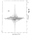
- a method for generating an excitation pulse that has a composition suitable for focusing the energy applied by that pulse to the pipetting needle is described as follows. To simplify the description and make it easier to understand the method is described for the simplified case of a pipetting needle which has the shape of simple empty tube, which does not contain any liquid and which is not mechanically coupled with any electromechanical transducer. A FDM code of the above mentioned case is written for this case and is used for the simulation. Three Hanning pulses comprising each five periods of their central frequencies of 0.5 MHz, 1.2 MHz and 2.7 MHz are symmetrically superposed in order to form a desired pulse 21 shown by Fig. 10 which should be the pulse resulting of focusing the excitation pulse applied to the needle.
- this desired pulse 21 is applied at the spot 22, where the mechanical pulses should be focused in the real experiment, and a signal 25 shown by Fig. 11 is recorded at the spot 24, where the mechanical excitation pulse is applied to the needle in the real experiment.
- Time reversal of recorded signal 25 and selection of a portion of this signal with a suitable time window provides the excitation pulse 26.
- the time window is so chosen that only the first arriving pulses are considered, but not those already reflected.
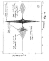
- An excitation pulse 26 obtained in the latter way is applied at spot 24 of the needle and this provides the desired focused pulse 21 shown in Fig. 12
- the first mode is a torsional mode.
- the second mode is a longitudinal mode.
- Fig. 11 shows four pulses of different modes which reach spot 24 in Fig. 5 and which are the result of applying a pulse 21 at spot 22 in Fig. 5.
- excitation pulse 26 consists of four pulses.
- Fig. 12 shows six pulses that arise at the right end 22 of the capillary tube when a mechanical excitation corresponding to excitation pulse 26 is applied at spot 24. The latter six pulses result from the four pulses of the excitation pulse 26, because above 2 MHz there are 2 propagation modes.
- the method just described above is just a simplified example of a method for focusing mechanical pulses.
- a pipetting needle For the purpose of releasing drops from the delivery tip of a pipetting needle not only the behavior of a capillary tube (pipetting needle), but also the behavior of a piezoelectric transducer used for applying the mechanical pulses is simulated. Simulation of the behavior of a liquid in the interior of the needle is less important than simulation of the behavior of the capillary tube and the piezoelectric transducer, because the liquid in the needle has less influence on the process for releasing a drop by the above described method.
- a suitable FDM code of the above mentioned kind is also available for performing a simulation of the behavior of the capillary tube and the piezoelectric transducer for the propagation of a mechanical pulse applied by the transducer to the capillary tube. If the simulation includes simulation of the behavior of the piezoelectric transducer, a voltage would be recorded that corresponds to the displacements shown in Fig. 11.
- the above described method for generating an excitation pulse suitable for performing the above mentioned dispensing method and in particular for exciting an electromechanical transducer in a micropipetting apparatus of the kind described hereinafter essentially comprises:
- a first embodiment of a micropipetting apparatus according to the invention is described hereinafter with reference to Figures 13 and 14.
- This micropipetting apparatus is suitable for dispensing a liquid volume into a vessel by means of a pipetting needle and without any contact between said needle and a liquid contained in said vessel.
- a micropipetting apparatus comprises a pipetting needle 11, a needle holder 31, an electromechanical transducer 32, a generator 33 for generating electrical signals, a connecting piece 34 which fluidically connects needle 11 with a conduit 35 which connects needle 11 with a source of positive or negative pressure, a transport system 36 for transporting needle holder 31 and a control unit 37 for controlling the operation of the entire system.
- Needle 11 has a substantially constant cross-section over the portion thereof that ends in a delivery tip 22 and that portion extends over more than one half of the total length of needle 11.
- Electromechanical transducer 32 is e.g. a piezoelectric transducer mechanically connected pipetting needle 11. This piezoelectric transducer comprises one or more piezoelectric elements.
- Transport system 36 comprises an arm 38 which carries needle holder 31.
- Fig. 14 shows a cross-sectional view of arm 38, needle holder 31, electromechanical transducer 32 and of a portion of needle 11.
- Signal generator 33 generates an excitation pulse signal and applies this signal to piezoelectric transducer 32 for mechanically exciting pipetting needle 11 at an excitation point 24 with an excitation pulse 26 that propagates along needle 11 and is focused at the end tip 22 thereof (as shown in Figures 8 and 9). The latter mechanical excitation thereby causes release of a drop from tip 22 of needle 11.
- composition of the excitation pulse 26 is adapted to the length and the wave propagation characteristic of the portion of needle 11 that has a substantially constant cross-section.
- piezoelectric element is radially polarized.
- piezoelectric element is axially polarized.
- the composition of excitation pulse 26 signal applied to piezoelectric transducer 32 is such that it causes a mainly radial displacement of liquid within said needle.
- composition of excitation pulse 26 signal applied to piezoelectric transducer 32 is such that it causes a mainly axial displacement of liquid within said needle.
- the excitation signal 26 applied at the excitation point 24 of needle 11 is generated by a method as described above with reference to Figures 4-12.
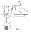
- Fig. 15 shows a second embodiment of an apparatus according to the invention.
- the apparatus shown by Fig. 15 comprises basically the same components as the apparatus described above with reference to Figures 13 and 14, but comprises in addition means for liquid level detection of the type described in a co-pending application No...................annaentitled "Level sensor apparatus for detecting contact of a pipetting needle with a liquid in a vessel” and filed on the same date by the same applicant.
- the contents of the latter co-pending application are incorporated herein by reference.
- the apparatus of this second embodiment comprises in addition to the components shown in Fig. 13: a signal generator 43 generates a driving signal and applies this signal to an actor part of piezoelectric transducer 32 for causing vibration of pipetting needle 11 at its resonance frequency, and an electronic circuit 44 for level detection.
- the apparatus shown by Fig. 15 comprises also means for measuring a vibration signal representative of the vibration of pipetting needle 11 when it is driven by a driving signal provided by signal generator 43.
- Electronic circuit 44 for level detection receives a vibration signal output from a sensor part of piezoelectric transducer 32.
- Electronic circuit 44 comprises means for evaluating the variation of the latter vibration signal with time for detecting contact of the pipetting needle with the free surface 47 of a liquid 48 contained in a vessel 41 and for providing a resulting signal representative of the result of said evaluation.
- Electronic circuit 44 comprises means for measuring amplitude and phase of vibration signal provided by the sensor part of transducer 32 or a combination of both signal components of that vibration signal.
- liquid level detection and drop ejection can not be performed at the same time, because the same electromechanical transducer is used for both purposes.
- the dimensions of the pipetting needle shown in Fig. 16 are as follows: Dimension Size in millimeter A1 69 L1 86 L2 5 L3 9 D1 0.9 D2 1.5 D3 3 D4 5 L4 13.5 L5 0.5 D5 0.6
- the tip 23 of needle has the cylindrical shape shown and that tip is shown to have a diameter D5.
- Another embodiment of the pipetting needle shown in Fig. 17 has a similar shape and dimensions, but the tip of the needle has a sharp end which is suitable for piercing a closure of a vessel.
Abstract
A method and a micropipetting apparatus for dispensing a
liquid volume into a vessel by means of a pipetting needle
(11) and without any contact between said needle and a
liquid contained in said vessel. The method comprises (a)
forming a drop (17) at the delivery tip of a pipetting
needle (11), said drop being retained at the tip by adhesion
forces, and (b) ejecting said drop (17) from said tip by
focusing a mechanical wave at the tip of the pipetting
needle.
The apparatus comprises

Description
- The invention concerns a method for dispensing a liquid volume into a vessel by means of a pipetting needle and without any contact between said needle and a liquid contained in said vessel.
- The invention further concerns a micropipetting apparatus for dispensing a liquid volume into a vessel by means of a pipetting needle and without any contact between said needle and a liquid contained in said vessel.
- The invention further concerns a method for generating an excitation pulse signal suitable for exciting a piezoelectric element used as electromechanical transducer in a micropipetting apparatus of the above mentioned kind.
- Pipetting of liquids is an important function of automatized analysis of samples examined for the purposes of medical diagnosis. Mastering of the pipetting operations is a basic condition for performing analysis which are correct, fast, cheap and ecological. There is a need for a pipetting apparatus which is able to pipette with the required accuracy liquid volumes in the nanoliter and microliter range.
- Dispensing of very small liquid volumes requires contact of the pipetting needle with a solid surface or with another liquid to which the dispensed volume is added. This is so because the adhesion forces which retain the small volume to be dispensed to the pipetting needle are larger than the weight of that small liquid volume. This weight alone is thus not sufficient for releasing a drop attached by adhesion forces to the tip of a pipetting needle. In prior art automatic pipetting apparatus of analyzers used for medical diagnosis a drop of a liquid to be dispensed is therefore brought into contact with and thereby delivered into another liquid, which can be a sample or a reagent. In order to avoid erroneous analysis results, it is necessary to clean the pipetting needle after each such contact with liquid in a container and this requires a lot of time.
- According to prior art delivery of a liquid to be dispensed can only be achieved by contact of the tip of the pipetting needle with a liquid contained in a container which receives the dispensed liquid. In some applications it is however desirable to dispense a liquid without any contact between the tip of the pipetting needle and a liquid contained in a container that receives the dispensed liquid, since in this case cleaning of the needle would not be any more necessary after each dispensing operation. This is the case e.g. when aliquots of a liquid sample are have to be distributed to liquids contained in a plurality of containers. In this case the time for distributing the aliquots to the plurality of containers would be considerably reduced, because it would not be necessary to clean the pipetting needle after dispensing each aliquot.
- Fig. 1 shows a prior art dispensing of very small aliquots of a liquid to a plurality of different vessels. As shown in Fig. 1, a
pipetting needle 11 is used for taking a sample of liquid contained in avessel 12 and for successively dispensing aliquots of that sample todifferent vessels tip needle 11 has to contact a liquid contained in thevessel needle 11 has to be cleaned after each such dispensing, before dispensing an aliquot in a different vessel. Fig. 1 showscleaning positions 15 and 16 of the pipetting needle. In Fig. 1 arrows represent the sense of motion of the pipetting needle during the above-mentioned dispensing operations. - Drops can be dispensed for instance like in inkjet printers, wherein a pressure pulse is generated within a liquid and this pulse propagates towards a nozzle which closes one end of a container which contains the liquid to be dispensed. Due to the reduction of the cross-section at the transition from the interior of the container to the nozzle, a small liquid volume is strongly accelerated and this allows to release through the nozzle one drop of liquid from the container. The size of a drop generated by the inkjet principle lies in a range going from 5 to 500 picoliter and depends from the properties of the liquid and from the size of the nozzle. Drops generated only by the weight of the drop to be dispensed are much larger. When a pipetting needle having a cross-section with an external diameter of 10 micrometer is used for dispensing drops only by means of gravitational force (i.e. the weight of the drop) the size of each drop would be of 30 nanoliter if the liquid dispensed is an aqueous solution.
- For dispensing drops by the inkjet principle a very strong acceleration of the liquid volume in the nozzle is necessary (accelerations of up to 105 g). The energy required for releasing a 500 picoliter drop is of about 10-8 Joule.
A nozzle of the type used in inkjet printers cannot be a part of a pipetting needle of an analyzer for analyzing samples for the purposes of medical analysis, because the structure of the pipetting needle should allow the required sufficient cleaning of the pipetting needle as often as required the presence of a nozzle in the structure of the pipetting needle would render this impossible. Other requirements the pipetting needle should fulfill are: - it should be suitable for piercing a closure of a liquid container, and
- it should have an elongated shape and should be long enough to penetrate deep enough in a liquid container.
- All these required features of the pipetting needle show that important features of the needle are dictated by the intended use of the pipetting needle and cannot be modified.
- A first aim of the invention is therefore to provide a method and an apparatus of the above mentioned kind which enables a contact-free dispensing of liquid drops from the tip of a pipetting needle which can be properly cleaned by washing it with conventional washing means and which is suitable for piercing a closure of a vessel.
- A second aim of the invention is to provide a method for generating an excitation pulse signal suitable for exciting a piezoelectric element used as electromechanical transducer in a micropipetting apparatus of the above mentioned kind, said excitation pulse signal being such that energy generated by the electromechanical transducer is focused at a desired point.
- According to a first aspect of the invention the above mentioned first aim is achieved with a method according to
claim 1. - According to a second aspect of the invention the above mentioned first aim is achieved with a micropipetting apparatus according to
claim 3. - According to a third aspect of the invention the above mentioned second aim is achieved with a method for generating an excitation pulse signal according to
claim 11. - According to a fourth aspect of the invention the above mentioned is achieved with an apparatus as defined by
claim 10, which enables a contact-free dispensing of liquid drops according to the invention in combination with level detection capability. - The methods and apparatus according to the invention have the following advantages:
- The method allows a contact-free dispensing of drops without including a nozzle in the structure of the pipetting needle. A thorough cleaning of the pipetting needle is therefore possible.
- The method allows use of pipetting needles having various shapes and dimensions.
- Release of drops from a pipetting needle is achieved by use of a piezoelectric actor and does not require use of any movable part.
- The method for dispensing drops can be combined with a method for liquid level detection based on mechanical vibration of the pipetting needle at a resonant frequency; the latter vibration being effected with the same piezoelectric actor that is used for dispensing drops from a pipetting needle.
- A complete system including the piezoelectric transducer and liquid contained in the pipetting needle can be simulated by means of an FDM-Code.
- The subject invention will now be described in terms of its preferred embodiments with reference to the accompanying drawings. These embodiments are set forth to aid the understanding of the invention, but are not to be construed as limiting.
- Fig. 1 shows schematically a prior art method for
dispensing aliquots of a liquid sample taken with a
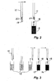
pipetting needle 11 from avessel 12 to a plurality ofvessels - Fig. 2 shows schematically the principle of a method
according to the invention for dispensing aliquots of a
liquid sample taken with a
pipetting needle 11 from avessel 12 to anothervessel 13. - Fig. 3 shows schematically successive dispensing of
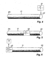
drops different vessels - Fig. 4 shows schematically a simulation step wherein a
desired focused
mechanical pulse 21 is applied as excitation pulse at apoint 22 of apipetting needle 11 wherein focusedpulse 21 should result in a real experiment.Point 22 is the drop delivery tip ofneedle 11. - Fig. 5 shows schematically a further simulation step
corresponding to the
propagation 23 of the mechanical pulse applied atpoint 22 in Fig. 4 towards a desiredexcitation point 24 in a real experiment.Point 24 is the point ofneedle 11 where a mechanical excitation pulse is applied in a real experiment. - Fig. 6 shows schematically a further simulation step
wherein a
signal 25 is recorded which corresponds to a mechanical pulse which reachespoint 24 in Fig. 5 as a result of thepropagation 23 represented in Fig. 5. - Fig. 7 shows schematically time inversion of recorded
signal 25 for generating anexcitation pulse 26. - Fig. 8 shows schematically application of
excitation pulse 26 atexcitation point 24 ofneedle 11 andpropagation 27 of that pulse towardspoint 24 ofneedle 11. - Fig. 9 shows schematically a desired focused
mechanical pulse 21 which reachespoint 22 as a result of thepropagation 27 represented in Fig. 8. - Fig. 10 shows an example of a wave shape of a desired
focused
mechanical pulse 21 which should reachpoint 22 ofneedle 11 in a simplified structure not taking into account any liquid contained inneedle 11 and without any electromechanical transducer mechanically connected withneedle 11. Such apulse 21 is used in a simulation of the type represented in Fig. 4. - Fig. 11 shows an example of a wave shape of a
signal 25 which is recorded atpoint 24 when amechanical pulse 21 is applied atpoint 22 in a simulation step of the type represented in Fig. 5 and under the conditions mentioned in the above description of Fig. 10. - Fig. 12 shows an example of a wave shape of a desired
focused
mechanical pulse 21 which reachespoint 22 ofneedle 10 when asignal 26 is applied topoint 24 ofneedle 11 and saidsignal 26 is obtained from asignal 25 shown in Fig. 11 by the method step represented in Fig. 7 and under the conditions mentioned in the above description of Fig. 10. - Fig. 13 shows a block diagram of the structure of a first embodiment of micropipetting apparatus according to the invention.
- Fig. 14 shows an enlarged view of a part of the block diagram shown by Fig. 13.
- Fig. 15 shows a block diagram of the structure of a second embodiment of micropipetting apparatus according to the invention.
- Fig. 16 shows schematically the shape and dimensions of a
first embodiment of pipetting
needle 12 in Fig. 1. - Fig. 17 shows schematically the shape and dimensions of a
second embodiment of pipetting
needle 12 in Fig. 1. -
- A method according to the invention is described hereinafter with reference to Figures 2 to 12. This method is suitable for dispensing a liquid volume into a vessel by means of a pipetting needle and without any contact between said needle and a liquid contained in said vessel.
- As shown in Fig. 2 a volume of liquid 17 corresponding to the volume of a drop to be dispensed is formed at the
tip 22 of apipetting needle 11 by exerting pressure on the liquid contained in the interior of the pipetting needle. Adhesion forces retain the drop so formed attached to thetip 22 of thepipetting needle 11. By performing a method described hereinafter thevolume 17 is ejected from the tip ofneedle 11 as adrop 18 which is delivered to and thereby added to a liquid contained in avessel 13. It should be noted thatdrop 18 is delivered without any contact betweenneedle 11 and a liquid contained invessel 13. - Fig. 3 illustrates a successive dispensing of
drops different vessels - The invention makes use of the fact that the tubular wall of the
pipetting needle 11 is a dispersive medium for the transmission of mechanical waves. - The portion of the pipetting needle used according to the invention for the above mentioned transmission of mechanical waves is shown in Figures 4 to 9. This portion has the shape of a capillary tube.
- According to the invention a suitable composite mechanical excitation pulse is applied at a
point 24 of the pipetting needle which lies at some distance from theneedle delivery tip 22 from which the drops are ejected. The latter excitation pulse and the mechanical system comprising theneedle 11, the liquid in the needle and the means for generating the excitation pulse, e.g. a piezoelectric transducer connected to the needle, are so configured that the excitation pulse has frequency components which arrive simultaneously to thedrop delivery tip 22 of the needle and thereby provide a maximum of mechanical energy at that tip. In other words the latter configuration is such that transmission of the excitation pulse by the mechanical system mentioned above focuses the mechanical wave at thetip 22 of the pipetting needle and reflection of the focused wave at that tip causes ejection of a drop which was held there by adhesion forces. - According to the invention a
drop 17 is formed at thedelivery tip 22 of thepipetting needle 11 by pressing a predetermined liquid volume out of the needle and thereby forming a liquid meniscus at thedelivery tip 22 of the pipetting needle. After that the above mentioned transmission of mechanical waves can take place, e.g. in one of the following ways: - 1) A mechanical excitation pulse is applied to the needle
at
point 24. This pulse causes displacements in the tubular wall of theneedle 11 mainly in axial direction and is focused at thedelivery tip 22 of the needle. The reflection of this pulse at thedelivery tip 22 of the pipetting needle releases drop 17 from that tip. - 2) A mechanical excitation pulse is applied to the
needle 11. This pulse causes displacements in the tubular wall of the needle mainly in radial direction. Due to mechanical coupling of the tubular wall of theneedle 11 and liquid contained in the needle, liquid within the needle is also displaced and accelerated towards thedelivery tip 22 of the needle by the propagation of the excitation pulse. This displacement of fluid and the focusing and reflection of the excitation pulse at thedelivery tip 22 of the pipetting needle releases drop 17 from that tip. -
- The above described method for dispensing a liquid thus essentially comprises
- (a) forming a
drop 17 at thedelivery tip 22 of apipetting needle 11, said drop being retained at the tip by adhesion forces, and - (b) ejecting the
drop 17 from thetip 22 by focusing a mechanical wave at thetip 22 of thepipetting needle 11. -
- In a preferred embodiment the ejection of the drop is achieved by mechanically exciting the needle by means of an excitation pulse having a composition that focuses a pulsed wave at the tip of said pipetting needle. A superposition of a focused incident wave with a reflected wave at the delivery tip of the pipetting needle causes ejection of the drop from the tip. As described hereinafter a suitable composition of the excitation pulse is obtained by a simulation process.
- In order to generate an excitation pulse which has a suitable composition or structure, the wave propagation of the excitation pulse in a system comprising a needle filled with a liquid and a piezoelectric actuator mechanically connected with the needle is simulated by means of finite difference method (FDM). After that an excitation pulse with a suitable structure is then calculated by a time reversal method.
- In order to simulate the above mentioned wave propagation a FDM code is written for the case of an axial symmetric tube, filled with a liquid and mechanically connected to a piezoelectric transducer. The latter FDM code is based on a code described in the publication: Thesis of Tobias F. Leutenegger entitled "Detection of defects in cylindrical structures using a time reverse numerical simulation method" Diss. Swiss Federal Institute of Technology Zurich (ETH Zürich) No. 14833, 2002.
- The FDM code is programmed with second order central differences, a so called staggered grid being used for discretization in space and time. The liquid is modeled as an acoustical fluid. In this way the behavior of the complete system can be simulated. By means of the FDM code the excitation pulses necessary for the desired energy focusing are computed making use of a time reversal method. The principle of this method is described as follows with reference to Figures 4 to 12, wherein a portion of pipetting needle is shown, and this portion has the shape of a capillary tube:
- A real experiment with the pipetting needle is
described by / simulated with a FDM code. The
spot 24, where the mechanical excitation pulse is applied to the needle, and thespot 22, where the mechanical pulses should be focused, are defined. - In the FDM code a desired
focused pulse 21 is applied as excitation pulse at thespot 22, where the mechanical pulses should be focused in the real experiment. - The propagation of the mechanical wave is simulated
over a time interval which extends until the excitation
pulse passes through the
spot 24, where the mechanical excitation pulse is applied to the needle in the real experiment. - The displacements in all directions are recorded as a
signal 25 over a time interval at thespot 24, where the mechanical excitation pulse is applied to the needle in the real experiment. - The recorded
signal 25 is reversed in time for generating asignal 26 which is the excitation signal that has to be applied atspot 24, where the mechanical excitation pulse is applied to the needle in the real experiment, in order to obtain a desiredfocused pulse 21 at thespot 22, where the mechanical pulses should be focused in the real experiment (see Figures 7 to 9). - The result of the above mentioned calculation is the
electrical signal 26 to be applied to the piezoelectric transducer. This signal is generated by a function generator. A piezoelectric tube with electrodes on its major surfaces (radial electric field) and radial polarization generates mainly radial displacements. A piezoelectric tube with electrodes on its major surfaces (radial electric field) and axial polarization generates mainly axial displacements. Generation of the desired displacements in the pipetting needle can thus be obtained by election of a suitable piezoelectric transducer. - A method for generating an excitation pulse that has a composition suitable for focusing the energy applied by that pulse to the pipetting needle is described as follows. To simplify the description and make it easier to understand the method is described for the simplified case of a pipetting needle which has the shape of simple empty tube, which does not contain any liquid and which is not mechanically coupled with any electromechanical transducer. A FDM code of the above mentioned case is written for this case and is used for the simulation.
Three Hanning pulses comprising each five periods of their central frequencies of 0.5 MHz, 1.2 MHz and 2.7 MHz are symmetrically superposed in order to form a desiredpulse 21 shown by Fig. 10 which should be the pulse resulting of focusing the excitation pulse applied to the needle. In the simulation this desiredpulse 21 is applied at thespot 22, where the mechanical pulses should be focused in the real experiment, and asignal 25 shown by Fig. 11 is recorded at thespot 24, where the mechanical excitation pulse is applied to the needle in the real experiment. Time reversal of recordedsignal 25 and selection of a portion of this signal with a suitable time window provides theexcitation pulse 26. The time window is so chosen that only the first arriving pulses are considered, but not those already reflected. Anexcitation pulse 26 obtained in the latter way is applied atspot 24 of the needle and this provides the desired focusedpulse 21 shown in Fig. 12 - The meaning of n and m in the labels of Figures 11 and 12 is as follows:
- n is the azimuthal wave number and describes wave modes with regard to their azimuthal characteristic.
- n = 0 means that the wave mode has an axial symmetry.
- n = 1 means that the displacements have one maximum and one minimum over the circumference.
- n = 2 means that the displacements have two maxima and two minima over the circumference.
-
- Modes of a given wave number n are numbered in the order of their appearance with m= 1, m=2, etc.
- In the case of a capillary tube, e.g. the portion of a pipetting needle shown by Figures 4 to 9, and at low frequencies, there are only a first mode with n = 0, m =1 and a second mode with n = 0 and m =2 which have both an axial symmetry. The first mode is a torsional mode. At sufficiently low frequencies the second mode is a longitudinal mode. A third mode with n = 0, m = 3 arises at a frequency of 2 MHz.
- Displacements in radial and axial direction at the complete front surface of the left end of the capillary are recorded. In Fig. 11 only axial displacements at the inner diameter of the left end of the capillary are represented.
- In order to obtain a most suitable excitation signal, it would be advantageous to record displacements over the entire front surface of the left end of the capillary, but recording of displacements at a few point of that surface would suffice.
- Fig. 11 shows four pulses of different modes which reach
spot 24 in Fig. 5 and which are the result of applying apulse 21 atspot 22 in Fig. 5. The latter four pulses have different group velocities. Therefore, as shown by Fig. 11 these pulses reach the front surface of the left end of the capillary at different points of time. The latest pulse which reaches the latter front surface is already reflected once by the left and once by the right end of the capillary tube. This pulse should not be taken into consideration when forming the excitation pulse on the basis of the pulses shown by Fig. 11. Therefore, the time window used for forming this pulse should extend from t = 0 s to about t = 0.9 10-4 s. Reversal in time of the portion of the pulses shown in Fig. 11 which are within the latter window provide an excitation pulse 26 (shown in Fig. 8) propagation of which results in apulse 21 atspot 22 in Fig. 9. In the generation ofexcitation pulse 26 it is important to take into account both the axial and the radial displacements obtained by simulation at the front surface of the left end of the capillary. In the attached drawings only the axial displacements are represented. - The above mentioned
excitation pulse 26 consists of four pulses. Fig. 12 shows six pulses that arise at theright end 22 of the capillary tube when a mechanical excitation corresponding toexcitation pulse 26 is applied atspot 24. The latter six pulses result from the four pulses of theexcitation pulse 26, because above 2 MHz there are 2 propagation modes. - Four of the above mentioned six pulses form focused
pulse 21 shown in the gray area of Fig. 12. Two other modes outside of this gray area are also represented in Fig. 12. These two modes, which are not desirable, but are also generated by the excitation withpulse 26, reach theright end 22 of the capillary tube at other points of time. The latter modes do not interfere with the release of a drop from the tip of the pipetting needle, because they lie outside of the time window of the desiredpulse 21 which is used for releasing the drop. - The method just described above is just a simplified example of a method for focusing mechanical pulses. For the purpose of releasing drops from the delivery tip of a pipetting needle not only the behavior of a capillary tube (pipetting needle), but also the behavior of a piezoelectric transducer used for applying the mechanical pulses is simulated. Simulation of the behavior of a liquid in the interior of the needle is less important than simulation of the behavior of the capillary tube and the piezoelectric transducer, because the liquid in the needle has less influence on the process for releasing a drop by the above described method.
- A suitable FDM code of the above mentioned kind is also available for performing a simulation of the behavior of the capillary tube and the piezoelectric transducer for the propagation of a mechanical pulse applied by the transducer to the capillary tube. If the simulation includes simulation of the behavior of the piezoelectric transducer, a voltage would be recorded that corresponds to the displacements shown in Fig. 11.
- The above described method for generating an excitation pulse suitable for performing the above mentioned dispensing method and in particular for exciting an electromechanical transducer in a micropipetting apparatus of the kind described hereinafter essentially comprises:
- (a) simulating by means of a finite difference method propagation of a mechanical pulse through the wall of a portion of a pipetting needle that has the shape of a capillary tube, said pulse being applied in the simulation at the spot where in the real experiment a focused pulse is to be generated for thereby ejecting a drop formed at the delivery tip of the needle and attached thereto by adhesion forces,
- (b) recording an electrical pulse signal which correspond to mechanical pulses which in the simulation arise at the spot where the mechanical excitation pulse is to be applied to said pipetting needle in reality, and
- (c) calculating an excitation pulse signal to be applied in reality to said piezoelectric transducer, the latter excitation pulse signal being calculated by time reversal of said recorded signal obtained by step (b).
-
- A first embodiment of a micropipetting apparatus according to the invention is described hereinafter with reference to Figures 13 and 14. This micropipetting apparatus is suitable for dispensing a liquid volume into a vessel by means of a pipetting needle and without any contact between said needle and a liquid contained in said vessel.
- As shown by Fig. 13 a micropipetting apparatus according to the invention comprises a
pipetting needle 11, aneedle holder 31, anelectromechanical transducer 32, agenerator 33 for generating electrical signals, a connectingpiece 34 which fluidically connectsneedle 11 with aconduit 35 which connectsneedle 11 with a source of positive or negative pressure, atransport system 36 for transportingneedle holder 31 and acontrol unit 37 for controlling the operation of the entire system. -
Needle 11 has a substantially constant cross-section over the portion thereof that ends in adelivery tip 22 and that portion extends over more than one half of the total length ofneedle 11. -
Electromechanical transducer 32 is e.g. a piezoelectric transducer mechanically connected pipettingneedle 11. This piezoelectric transducer comprises one or more piezoelectric elements. -
Transport system 36 comprises anarm 38 which carriesneedle holder 31. - Fig. 14 shows a cross-sectional view of
arm 38,needle holder 31,electromechanical transducer 32 and of a portion ofneedle 11. -
Signal generator 33 generates an excitation pulse signal and applies this signal topiezoelectric transducer 32 for mechanicallyexciting pipetting needle 11 at anexcitation point 24 with anexcitation pulse 26 that propagates alongneedle 11 and is focused at theend tip 22 thereof (as shown in Figures 8 and 9). The latter mechanical excitation thereby causes release of a drop fromtip 22 ofneedle 11. - In a preferred embodiment the composition of the
excitation pulse 26 is adapted to the length and the wave propagation characteristic of the portion ofneedle 11 that has a substantially constant cross-section. - In a preferred embodiment, piezoelectric element is radially polarized.
- In another preferred embodiment, piezoelectric element is axially polarized.
- In a preferred embodiment, the composition of
excitation pulse 26 signal applied topiezoelectric transducer 32 is such that it causes a mainly radial displacement of liquid within said needle. - In another preferred embodiment, the composition of
excitation pulse 26 signal applied topiezoelectric transducer 32 is such that it causes a mainly axial displacement of liquid within said needle. - In all above described embodiments of the micropipetting apparatus described with reference to Figures 13 and 14, the
excitation signal 26 applied at theexcitation point 24 ofneedle 11 is generated by a method as described above with reference to Figures 4-12. - Fig. 15 shows a second embodiment of an apparatus according to the invention.
- The apparatus shown by Fig. 15 comprises basically the same components as the apparatus described above with reference to Figures 13 and 14, but comprises in addition means for liquid level detection of the type described in a co-pending application No..................................entitled "Level sensor apparatus for detecting contact of a pipetting needle with a liquid in a vessel" and filed on the same date by the same applicant. The contents of the latter co-pending application are incorporated herein by reference.
- As shown by Fig. 15 the apparatus of this second embodiment comprises in addition to the components shown in Fig. 13: a
signal generator 43 generates a driving signal and applies this signal to an actor part ofpiezoelectric transducer 32 for causing vibration of pipettingneedle 11 at its resonance frequency, and anelectronic circuit 44 for level detection. - The apparatus shown by Fig. 15 comprises also means for measuring a vibration signal representative of the vibration of pipetting
needle 11 when it is driven by a driving signal provided bysignal generator 43. -
Electronic circuit 44 for level detection receives a vibration signal output from a sensor part ofpiezoelectric transducer 32.Electronic circuit 44 comprises means for evaluating the variation of the latter vibration signal with time for detecting contact of the pipetting needle with thefree surface 47 of a liquid 48 contained in avessel 41 and for providing a resulting signal representative of the result of said evaluation. -
Electronic circuit 44 comprises means for measuring amplitude and phase of vibration signal provided by the sensor part oftransducer 32 or a combination of both signal components of that vibration signal. - It should be clear that liquid level detection and drop ejection can not be performed at the same time, because the same electromechanical transducer is used for both purposes.
- The dimensions of the pipetting needle shown in Fig. 16 are as follows:
Dimension Size in millimeter A1 69 L1 86 L2 5 L3 9 D1 0.9 D2 1.5 D3 3 D4 5 L4 13.5 L5 0.5 D5 0.6 - In the embodiment of pipetting
needle 12 shown in Fig. 16 thetip 23 of needle has the cylindrical shape shown and that tip is shown to have a diameter D5. Another embodiment of the pipetting needle shown in Fig. 17 has a similar shape and dimensions, but the tip of the needle has a sharp end which is suitable for piercing a closure of a vessel. - Although preferred embodiments of the invention have been described using specific terms, such description is for illustrative purposes only, and it is to be understood that changes and variations may be made without departing from the spirit or scope of the following claims.
| REFERENCE NUMERALS IN | |
| 11 | |
| 12 | |
| 13 | |
| 14 | vessel |
| 15 | cleaning position of pipetting |
| 16 | cleaning position of pipetting |
| 17 | drop / volume of drop held by tip of |
| 18 | |
| 19 | drop |
| 20 | |
| 21 | focused pulse at tip of |
| 22 | drop delivery tip of pipetting needle / spot of pipetting needle where mechanical wave is focused |
| 23 | wave propagation along the pipetting |
| 24 | excitation point of pipetting |
| 25 | recorded signal at |
| 26 | time inverted signal derived from |
| 27 | wave propagation along the pipetting needle |
| 28 | |
| 29 | |
| 30 | |
| 31 | |
| 32 | electromechanical transducer / |
| 33 | generator of |
| 34 | connecting |
| 35 | |
| 36 | |
| 37 | |
| 38 | arm of transport system |
| 39 | |
| 40 | |
| 41 | vessel |
| 42 | |
| 43 | generator of an |
| 44 | electronic circuit for level detection |
| 45 | |
| 46 | |
| 47 | free surface of |
| 48 | liquid in vessel |
| 49 |
Claims (11)
- Method for dispensing a liquid volume into a vessel by means of a pipetting needle and without any contact between said needle and a liquid contained in said vessel, said method comprising(a) forming a drop (17) at the delivery tip (22) of a pipetting needle (11), said drop being retained at the tip by adhesion forces, and(b) ejecting said drop (17) from said tip (22) by focusing a mechanical wave at said tip of the pipetting needle (11).
- A method according to claim 1 wherein said ejecting of said drop (17) is achieved by mechanically exciting said needle (11) by means of an excitation pulse (26) having a composition that focuses a pulsed wave at the tip of said pipetting needle (11), a superposition of a focused incident wave with a reflected wave at the tip of the pipetting needle causing ejection of said drop (17) from said tip.
- Micropipetting apparatus for dispensing a liquid volume into a vessel by means of a pipetting needle and without any contact between said needle and a liquid contained in said vessel, said apparatus comprising(a) a pipetting needle (11) having a substantially constant cross-section over the portion thereof that ends in a delivery tip, said portion extending over more than one half of the total length of said needle(b) an electromechanical transducer (32) mechanically connected with said pipetting needle (11), and(c) electrical signal generating means (33) for generating an excitation pulse (26) signal and for applying this signal to said electromechanical transducer (32) for mechanically exciting said pipetting needle (11) with a pulse that propagates along said needle and is focused at the end tip thereof, said mechanical excitation thereby causing ejection of a drop (17) formed on the delivery tip of said pipetting needle.
- A micropipetting apparatus according to claim 3, wherein said excitation pulse (26) signal is adapted to the length and the wave propagation characteristic of said portion of the needle (11) that has a substantially constant cross-section.
- A micropipetting apparatus according to claim 3, wherein said electromechanical transducer (32) is a piezoelectric transducer.
- A micropipetting apparatus according to claim 5, wherein said piezoelectric transducer (32) is radially polarized.
- A micropipetting apparatus according to claim 5, wherein said piezoelectric transducer (32) is axially polarized.
- A micropipetting apparatus according to any of claims 5 to 7, wherein said excitation pulse (26) signal applied to said piezoelectric transducer (32) is so configured that it causes a mainly radial displacement of liquid within said needle (11).
- A micropipetting apparatus according to any of claims 5 to 7, wherein said excitation pulse (26) signal applied to said piezoelectric transducer (32) is so configured that it causes a mainly axial displacement of liquid within said needle (11).
- Micropipetting apparatus for dispensing a liquid volume into a vessel by means of a pipetting needle and without any contact between said needle and a liquid contained in said vessel, said apparatus comprising(a) a pipetting needle (11) having a substantially constant cross-section over the portion thereof that ends in a delivery tip, said portion extending over more than one half of the total length of said needle, said needle having a mechanical resonance frequency,(b) an electromechanical transducer (32) mechanically connected with said pipetting needle (11),(c) first electrical signal generating means (33) for generating an excitation pulse (26) signal and for applying this signal to said electromechanical transducer (32) for mechanically exciting said pipetting needle (11) with a pulse that propagates along said needle and is focused at the end tip thereof, said mechanical excitation thereby causing ejection of a drop (17) formed on the delivery tip of said pipetting needle,(d) second electrical signal generating means (43) for generating a driving signal and for applying this signal to said electromechanical transducer (32) for causing vibration of said pipetting needle (11) at said resonance frequency,(e) means for measuring a vibration signal representative of the vibration of said pipetting needle (11) when it is driven by said driving signal, and(f) means (44) for evaluating the variation of said vibration signal with time for detecting contact of the pipetting needle (11) with the free surface (47) of a liquid (48) contained in said vessel and for providing a resulting signal representative of the result of said evaluation.
- Method for generating an excitation pulse signal suitable for performing a method according to claim 2 and for exciting a piezoelectric transducer used as electromechanical transducer in a micropipetting apparatus according to any of claims 3 to 10, said method comprising(a) simulating by means of a finite difference method propagation of a mechanical pulse through the wall of a portion of a pipetting needle that has the shape of capillary tube, said pulse being applied in the simulation at the spot (22) where in the real experiment a focused pulse is to be generated for thereby ejecting a drop (17) formed at the delivery tip (22) of said needle (11) and attached thereto by adhesion forces,(b) recording an electrical pulse signal (25) which corresponds to mechanical pulses which in the simulation arise at the spot (24) where the mechanical excitation pulse is to be applied to said pipetting needle (11) in reality, and(c) calculating an excitation pulse signal (26) to be applied in reality to said piezoelectric transducer (32), the latter excitation pulse signal being calculated by time reversal of said recorded signal (25) obtained by step (b).
Priority Applications (8)
| Application Number | Priority Date | Filing Date | Title |
|---|---|---|---|
| EP04076436A EP1604741A1 (en) | 2004-05-14 | 2004-05-14 | Method and apparatus for dispensing a liquid with a pipetting needle |
| AT05075977T ATE373519T1 (en) | 2004-05-14 | 2005-04-25 | METHOD AND DEVICE FOR DISPENSING LIQUIDS USING A PIPETTING NEEDLE |
| EP05075977A EP1614469B1 (en) | 2004-05-14 | 2005-04-25 | Method and apparatus for dispensing a liquid with a pipetting needle |
| ES05075977T ES2293472T3 (en) | 2004-05-14 | 2005-04-25 | METHOD AND APPARATUS FOR DISPENSING A LIQUID WITH A PIPETE NEEDLE. |
| DE602005002499T DE602005002499T2 (en) | 2004-05-14 | 2005-04-25 | Method and device for supplying a liquid with a pipetting needle |
| CA2505216A CA2505216C (en) | 2004-05-14 | 2005-04-26 | Method and apparatus for dispensing a liquid with a pipetting needle |
| US11/128,677 US7615378B2 (en) | 2004-05-14 | 2005-05-13 | Pipetting needle |
| JP2005141507A JP4602154B2 (en) | 2004-05-14 | 2005-05-13 | Method and apparatus for dispensing liquid with pipette needle |
Applications Claiming Priority (1)
| Application Number | Priority Date | Filing Date | Title |
|---|---|---|---|
| EP04076436A EP1604741A1 (en) | 2004-05-14 | 2004-05-14 | Method and apparatus for dispensing a liquid with a pipetting needle |
Publications (1)
| Publication Number | Publication Date |
|---|---|
| EP1604741A1 true EP1604741A1 (en) | 2005-12-14 |
Family
ID=34928221
Family Applications (1)
| Application Number | Title | Priority Date | Filing Date |
|---|---|---|---|
| EP04076436A Withdrawn EP1604741A1 (en) | 2004-05-14 | 2004-05-14 | Method and apparatus for dispensing a liquid with a pipetting needle |
Country Status (7)
| Country | Link |
|---|---|
| US (1) | US7615378B2 (en) |
| EP (1) | EP1604741A1 (en) |
| JP (1) | JP4602154B2 (en) |
| AT (1) | ATE373519T1 (en) |
| CA (1) | CA2505216C (en) |
| DE (1) | DE602005002499T2 (en) |
| ES (1) | ES2293472T3 (en) |
Cited By (1)
| Publication number | Priority date | Publication date | Assignee | Title |
|---|---|---|---|---|
| DE102010001229A1 (en) * | 2010-01-26 | 2011-07-28 | Hamilton Bonaduz Ag | Aspirating and dispensing of liquid in pipetting devices with a pipetting tip, comprises inducing an oscillation mode of oscillation section of pipetting tip, measuring value of the induced oscillation mode and comparing with reference |
Families Citing this family (10)
| Publication number | Priority date | Publication date | Assignee | Title |
|---|---|---|---|---|
| US10457935B2 (en) | 2010-11-12 | 2019-10-29 | Gen9, Inc. | Protein arrays and methods of using and making the same |
| CN103429348B (en) | 2011-01-21 | 2016-03-09 | 拜奥-多特公司 | There is the piezo dispenser of longitudinal converter and replaceable capillary |
| US20130206857A1 (en) * | 2011-01-21 | 2013-08-15 | Biodot, Inc. | Piezoelectric dispenser with a longitudinal transducer and replaceable capillary tube |
| ES2737957T3 (en) | 2011-08-26 | 2020-01-17 | Gen9 Inc | Compositions and methods for high fidelity nucleic acid assembly |
| US9150853B2 (en) | 2012-03-21 | 2015-10-06 | Gen9, Inc. | Methods for screening proteins using DNA encoded chemical libraries as templates for enzyme catalysis |
| CN104603286B (en) | 2012-04-24 | 2020-07-31 | Gen9股份有限公司 | Method for sorting nucleic acids and multiplex preparations in vitro cloning |
| CN103472243B (en) * | 2012-06-06 | 2016-08-03 | 北京普源精仪科技有限责任公司 | A kind of automatic sampler and sampling probe |
| WO2018217702A1 (en) * | 2017-05-22 | 2018-11-29 | Gen9, Inc. | Device and method for nucleic acid manipulation |
| CN110064453B (en) * | 2018-01-24 | 2024-04-16 | 思纳福(苏州)生命科技有限公司 | Micro-droplet generation device and generation method |
| CN109908986B (en) * | 2019-02-21 | 2020-04-28 | 浙江大学 | Liquid drop generation system based on asymmetric outlet capillary and application method |
Citations (4)
| Publication number | Priority date | Publication date | Assignee | Title |
|---|---|---|---|---|
| US6003388A (en) * | 1997-09-17 | 1999-12-21 | The United States Of America As Represented By The Administrator Of The National Aeronautics And Space Administration | System for manipulating drops and bubbles using acoustic radiation pressure |
| US6232129B1 (en) * | 1999-02-03 | 2001-05-15 | Peter Wiktor | Piezoelectric pipetting device |
| US6296811B1 (en) * | 1998-12-10 | 2001-10-02 | Aurora Biosciences Corporation | Fluid dispenser and dispensing methods |
| US20040071601A1 (en) * | 2002-10-15 | 2004-04-15 | Larson Bradley James | Methods and apparata for precisely dispensing microvolumes of fluids |
Family Cites Families (15)
| Publication number | Priority date | Publication date | Assignee | Title |
|---|---|---|---|---|
| US4974458A (en) * | 1987-12-14 | 1990-12-04 | Ajinomoto Company, Inc. | Automatic preparation apparatus and support arm |
| JPH0781996B2 (en) * | 1988-08-27 | 1995-09-06 | 株式会社日立製作所 | Auto sampler |
| US5582798A (en) * | 1995-02-23 | 1996-12-10 | Cyberlab Inc. | Volume sensing device |
| JPH08338849A (en) * | 1995-04-11 | 1996-12-24 | Precision Syst Sci Kk | Method for detecting suction of liquid and dispenser being controlled by the method |
| US5750881A (en) * | 1995-07-13 | 1998-05-12 | Chiron Diagnostics Corporation | Method and apparatus for aspirating and dispensing sample fluids |
| JP3341023B2 (en) * | 1995-08-07 | 2002-11-05 | オムロン株式会社 | Spray apparatus and spray method using surface acoustic waves |
| EP1207396A1 (en) * | 2000-10-20 | 2002-05-22 | Seyonic SA | Fluid dispenser |
| CH695544A5 (en) * | 2000-11-17 | 2006-06-30 | Tecan Trading Ag | Apparatus for dispensing or aspirating / dispensing liquid samples. |
| US20020150511A1 (en) * | 2001-03-01 | 2002-10-17 | Peter Wiktor | Piezoelectric pipetting device housing and methods for making and using the same |
| JP2003050244A (en) * | 2001-08-07 | 2003-02-21 | Matsushita Electric Ind Co Ltd | Dispenser |
| JP3673782B2 (en) * | 2002-09-25 | 2005-07-20 | キヤノン株式会社 | Liquid ejection head, liquid ejection head driving method, and liquid ejection apparatus |
| US7097810B2 (en) * | 2002-06-26 | 2006-08-29 | The Public Health Research Institute Of The City Of New York, Inc. | Delivery of metered amounts of liquid materials |
| US7125727B2 (en) * | 2003-01-29 | 2006-10-24 | Protedyne Corporation | Sample handling tool with piezoelectric actuator |
| US7396512B2 (en) * | 2003-11-04 | 2008-07-08 | Drummond Scientific Company | Automatic precision non-contact open-loop fluid dispensing |
| US7258480B2 (en) * | 2005-01-10 | 2007-08-21 | Dade Behring Inc. | Apparatus for mixing liquid samples using a two dimensional stirring pattern |
-
2004
- 2004-05-14 EP EP04076436A patent/EP1604741A1/en not_active Withdrawn
-
2005
- 2005-04-25 AT AT05075977T patent/ATE373519T1/en active
- 2005-04-25 DE DE602005002499T patent/DE602005002499T2/en active Active
- 2005-04-25 ES ES05075977T patent/ES2293472T3/en active Active
- 2005-04-26 CA CA2505216A patent/CA2505216C/en not_active Expired - Fee Related
- 2005-05-13 JP JP2005141507A patent/JP4602154B2/en not_active Expired - Fee Related
- 2005-05-13 US US11/128,677 patent/US7615378B2/en not_active Expired - Fee Related
Patent Citations (4)
| Publication number | Priority date | Publication date | Assignee | Title |
|---|---|---|---|---|
| US6003388A (en) * | 1997-09-17 | 1999-12-21 | The United States Of America As Represented By The Administrator Of The National Aeronautics And Space Administration | System for manipulating drops and bubbles using acoustic radiation pressure |
| US6296811B1 (en) * | 1998-12-10 | 2001-10-02 | Aurora Biosciences Corporation | Fluid dispenser and dispensing methods |
| US6232129B1 (en) * | 1999-02-03 | 2001-05-15 | Peter Wiktor | Piezoelectric pipetting device |
| US20040071601A1 (en) * | 2002-10-15 | 2004-04-15 | Larson Bradley James | Methods and apparata for precisely dispensing microvolumes of fluids |
Cited By (1)
| Publication number | Priority date | Publication date | Assignee | Title |
|---|---|---|---|---|
| DE102010001229A1 (en) * | 2010-01-26 | 2011-07-28 | Hamilton Bonaduz Ag | Aspirating and dispensing of liquid in pipetting devices with a pipetting tip, comprises inducing an oscillation mode of oscillation section of pipetting tip, measuring value of the induced oscillation mode and comparing with reference |
Also Published As
| Publication number | Publication date |
|---|---|
| JP4602154B2 (en) | 2010-12-22 |
| JP2005326421A (en) | 2005-11-24 |
| CA2505216A1 (en) | 2005-11-14 |
| ES2293472T3 (en) | 2008-03-16 |
| US7615378B2 (en) | 2009-11-10 |
| DE602005002499T2 (en) | 2008-06-19 |
| DE602005002499D1 (en) | 2007-10-31 |
| ATE373519T1 (en) | 2007-10-15 |
| CA2505216C (en) | 2010-01-26 |
| US20060286678A1 (en) | 2006-12-21 |
Similar Documents
| Publication | Publication Date | Title |
|---|---|---|
| US7615378B2 (en) | Pipetting needle | |
| US7899645B2 (en) | Acoustic assessment of characteristics of a fluid relevant to acoustic ejection | |
| US20110000276A1 (en) | Method for checking the state of a pipette, pipetting method, pipetting device, and suction tube for a pipetting device | |
| US6938995B2 (en) | Acoustic assessment of fluids in a plurality of reservoirs | |
| CN103026241B (en) | Autoanalyzer | |
| CN101954788B (en) | Acoustic assessment of characteristics of a fluid relevant to acoustic ejection | |
| EP0903563B1 (en) | Device for the detection and/or monitoring of a predetermined level in a container | |
| JP2010522870A5 (en) | ||
| US20040119793A1 (en) | Acoustic assessment of fluids in a plurality of reservoirs | |
| US7454958B2 (en) | Acoustic determination of properties of reservoirs and of fluids contained therein | |
| DK161789B (en) | PROCEDURE AND APPARATUS FOR ULTRASONIC MONITORING AND MEASUREMENT OF THE PHYSICAL-CHEMICAL, BIOLOGICAL OR BACTERIOLOGICAL PHENOMENOMES | |
| US7281413B2 (en) | Acoustic method for determining the viscosity and/or surface tension of a liquid | |
| EP1614469B1 (en) | Method and apparatus for dispensing a liquid with a pipetting needle | |
| US20030005771A1 (en) | Two-dimensional array of ultrasonic sensors for high throughput fluid screening | |
| US4204434A (en) | Ultrasonic testing of welds in wheels | |
| WO2002092228A2 (en) | A method and device for dispensing of droplets | |
| Siber et al. | Effective Acoustic Field Generation in Disposable Dispensing Cartridges for Acoustophoretic Particle Focusin | |
| EP3173776B1 (en) | System and method for mixing and testing a liquid | |
| DE102021122534A1 (en) | Vibronic multisensor | |
| Capalbo et al. | Noncontact Determination of Fluid Properties by Means of Focused Acoustics |
Legal Events
| Date | Code | Title | Description |
|---|---|---|---|
| PUAI | Public reference made under article 153(3) epc to a published international application that has entered the european phase |
Free format text: ORIGINAL CODE: 0009012 |
|
| AK | Designated contracting states |
Kind code of ref document: A1 Designated state(s): AT BE BG CH CY CZ DE DK EE ES FI FR GB GR HU IE IT LI LU MC NL PL PT RO SE SI SK TR |
|
| AX | Request for extension of the european patent |
Extension state: AL HR LT LV MK |
|
| AKX | Designation fees paid | ||
| REG | Reference to a national code |
Ref country code: DE Ref legal event code: 8566 |
|
| STAA | Information on the status of an ep patent application or granted ep patent |
Free format text: STATUS: THE APPLICATION IS DEEMED TO BE WITHDRAWN |
|
| 18D | Application deemed to be withdrawn |
Effective date: 20060616 |