EP1604418B1 - Methods of operating fuel cells having closed reactant supply systems - Google Patents
Methods of operating fuel cells having closed reactant supply systems Download PDFInfo
- Publication number
- EP1604418B1 EP1604418B1 EP04717531.0A EP04717531A EP1604418B1 EP 1604418 B1 EP1604418 B1 EP 1604418B1 EP 04717531 A EP04717531 A EP 04717531A EP 1604418 B1 EP1604418 B1 EP 1604418B1
- Authority
- EP
- European Patent Office
- Prior art keywords
- fuel
- fuel cell
- supply pressure
- stack
- oxidant
- Prior art date
- Legal status (The legal status is an assumption and is not a legal conclusion. Google has not performed a legal analysis and makes no representation as to the accuracy of the status listed.)
- Expired - Lifetime
Links
- 239000000446 fuel Substances 0.000 title claims description 295
- 238000000034 method Methods 0.000 title claims description 45
- 239000000376 reactant Substances 0.000 title claims description 43
- 239000007800 oxidant agent Substances 0.000 claims description 47
- 230000001590 oxidative effect Effects 0.000 claims description 46
- 238000010926 purge Methods 0.000 claims description 24
- 239000001257 hydrogen Substances 0.000 claims description 16
- 229910052739 hydrogen Inorganic materials 0.000 claims description 16
- 239000005518 polymer electrolyte Substances 0.000 claims description 4
- 239000007787 solid Substances 0.000 claims description 4
- 230000003134 recirculating effect Effects 0.000 claims description 3
- 125000004435 hydrogen atom Chemical group [H]* 0.000 claims 1
- 238000012544 monitoring process Methods 0.000 claims 1
- 210000004027 cell Anatomy 0.000 description 156
- IJGRMHOSHXDMSA-UHFFFAOYSA-N Atomic nitrogen Chemical compound N#N IJGRMHOSHXDMSA-UHFFFAOYSA-N 0.000 description 56
- 229910052757 nitrogen Inorganic materials 0.000 description 28
- 239000012528 membrane Substances 0.000 description 18
- UFHFLCQGNIYNRP-UHFFFAOYSA-N Hydrogen Chemical compound [H][H] UFHFLCQGNIYNRP-UHFFFAOYSA-N 0.000 description 15
- 230000000712 assembly Effects 0.000 description 12
- 238000000429 assembly Methods 0.000 description 12
- 239000002826 coolant Substances 0.000 description 12
- XLYOFNOQVPJJNP-UHFFFAOYSA-N water Substances O XLYOFNOQVPJJNP-UHFFFAOYSA-N 0.000 description 10
- 238000001816 cooling Methods 0.000 description 8
- 239000012530 fluid Substances 0.000 description 7
- 238000009792 diffusion process Methods 0.000 description 6
- BASFCYQUMIYNBI-UHFFFAOYSA-N platinum Chemical compound [Pt] BASFCYQUMIYNBI-UHFFFAOYSA-N 0.000 description 6
- 239000003014 ion exchange membrane Substances 0.000 description 5
- 239000003054 catalyst Substances 0.000 description 4
- 238000006243 chemical reaction Methods 0.000 description 4
- 238000012360 testing method Methods 0.000 description 4
- 230000008901 benefit Effects 0.000 description 3
- 239000002737 fuel gas Substances 0.000 description 3
- 239000007789 gas Substances 0.000 description 3
- 239000007788 liquid Substances 0.000 description 3
- 229910052697 platinum Inorganic materials 0.000 description 3
- 229920000049 Carbon (fiber) Polymers 0.000 description 2
- 238000009825 accumulation Methods 0.000 description 2
- 230000035508 accumulation Effects 0.000 description 2
- 239000004917 carbon fiber Substances 0.000 description 2
- 238000004891 communication Methods 0.000 description 2
- 238000007599 discharging Methods 0.000 description 2
- 230000000694 effects Effects 0.000 description 2
- 230000005611 electricity Effects 0.000 description 2
- 239000004744 fabric Substances 0.000 description 2
- 239000000463 material Substances 0.000 description 2
- VNWKTOKETHGBQD-UHFFFAOYSA-N methane Chemical compound C VNWKTOKETHGBQD-UHFFFAOYSA-N 0.000 description 2
- 239000000047 product Substances 0.000 description 2
- 230000001052 transient effect Effects 0.000 description 2
- OKTJSMMVPCPJKN-UHFFFAOYSA-N Carbon Chemical compound [C] OKTJSMMVPCPJKN-UHFFFAOYSA-N 0.000 description 1
- MYMOFIZGZYHOMD-UHFFFAOYSA-N Dioxygen Chemical compound O=O MYMOFIZGZYHOMD-UHFFFAOYSA-N 0.000 description 1
- 238000013459 approach Methods 0.000 description 1
- QVGXLLKOCUKJST-UHFFFAOYSA-N atomic oxygen Chemical compound [O] QVGXLLKOCUKJST-UHFFFAOYSA-N 0.000 description 1
- 229910052799 carbon Inorganic materials 0.000 description 1
- 210000000170 cell membrane Anatomy 0.000 description 1
- 239000007795 chemical reaction product Substances 0.000 description 1
- 230000003247 decreasing effect Effects 0.000 description 1
- 230000001419 dependent effect Effects 0.000 description 1
- 238000010586 diagram Methods 0.000 description 1
- 238000010790 dilution Methods 0.000 description 1
- 239000012895 dilution Substances 0.000 description 1
- 229910001882 dioxygen Inorganic materials 0.000 description 1
- 238000003487 electrochemical reaction Methods 0.000 description 1
- 238000007710 freezing Methods 0.000 description 1
- 230000008014 freezing Effects 0.000 description 1
- 235000003642 hunger Nutrition 0.000 description 1
- 239000012535 impurity Substances 0.000 description 1
- 239000001301 oxygen Substances 0.000 description 1
- 229910052760 oxygen Inorganic materials 0.000 description 1
- 230000003071 parasitic effect Effects 0.000 description 1
- 230000000737 periodic effect Effects 0.000 description 1
- 230000002085 persistent effect Effects 0.000 description 1
- 229920000642 polymer Polymers 0.000 description 1
- 238000010248 power generation Methods 0.000 description 1
- 238000003825 pressing Methods 0.000 description 1
- 238000004064 recycling Methods 0.000 description 1
- 238000000926 separation method Methods 0.000 description 1
- 230000037351 starvation Effects 0.000 description 1
- 230000001960 triggered effect Effects 0.000 description 1
- 238000013022 venting Methods 0.000 description 1
- 239000002699 waste material Substances 0.000 description 1
Images


Classifications
-
- H—ELECTRICITY
- H01—ELECTRIC ELEMENTS
- H01M—PROCESSES OR MEANS, e.g. BATTERIES, FOR THE DIRECT CONVERSION OF CHEMICAL ENERGY INTO ELECTRICAL ENERGY
- H01M8/00—Fuel cells; Manufacture thereof
- H01M8/04—Auxiliary arrangements, e.g. for control of pressure or for circulation of fluids
- H01M8/04298—Processes for controlling fuel cells or fuel cell systems
- H01M8/04313—Processes for controlling fuel cells or fuel cell systems characterised by the detection or assessment of variables; characterised by the detection or assessment of failure or abnormal function
- H01M8/04537—Electric variables
- H01M8/04544—Voltage
- H01M8/04552—Voltage of the individual fuel cell
-
- H—ELECTRICITY
- H01—ELECTRIC ELEMENTS
- H01M—PROCESSES OR MEANS, e.g. BATTERIES, FOR THE DIRECT CONVERSION OF CHEMICAL ENERGY INTO ELECTRICAL ENERGY
- H01M8/00—Fuel cells; Manufacture thereof
- H01M8/04—Auxiliary arrangements, e.g. for control of pressure or for circulation of fluids
- H01M8/04082—Arrangements for control of reactant parameters, e.g. pressure or concentration
- H01M8/04089—Arrangements for control of reactant parameters, e.g. pressure or concentration of gaseous reactants
- H01M8/04104—Regulation of differential pressures
-
- H—ELECTRICITY
- H01—ELECTRIC ELEMENTS
- H01M—PROCESSES OR MEANS, e.g. BATTERIES, FOR THE DIRECT CONVERSION OF CHEMICAL ENERGY INTO ELECTRICAL ENERGY
- H01M8/00—Fuel cells; Manufacture thereof
- H01M8/04—Auxiliary arrangements, e.g. for control of pressure or for circulation of fluids
- H01M8/04298—Processes for controlling fuel cells or fuel cell systems
- H01M8/04313—Processes for controlling fuel cells or fuel cell systems characterised by the detection or assessment of variables; characterised by the detection or assessment of failure or abnormal function
- H01M8/04537—Electric variables
- H01M8/04544—Voltage
- H01M8/04559—Voltage of fuel cell stacks
-
- H—ELECTRICITY
- H01—ELECTRIC ELEMENTS
- H01M—PROCESSES OR MEANS, e.g. BATTERIES, FOR THE DIRECT CONVERSION OF CHEMICAL ENERGY INTO ELECTRICAL ENERGY
- H01M8/00—Fuel cells; Manufacture thereof
- H01M8/04—Auxiliary arrangements, e.g. for control of pressure or for circulation of fluids
- H01M8/04298—Processes for controlling fuel cells or fuel cell systems
- H01M8/04694—Processes for controlling fuel cells or fuel cell systems characterised by variables to be controlled
- H01M8/04746—Pressure; Flow
- H01M8/04753—Pressure; Flow of fuel cell reactants
-
- H—ELECTRICITY
- H01—ELECTRIC ELEMENTS
- H01M—PROCESSES OR MEANS, e.g. BATTERIES, FOR THE DIRECT CONVERSION OF CHEMICAL ENERGY INTO ELECTRICAL ENERGY
- H01M8/00—Fuel cells; Manufacture thereof
- H01M8/24—Grouping of fuel cells, e.g. stacking of fuel cells
- H01M8/2457—Grouping of fuel cells, e.g. stacking of fuel cells with both reactants being gaseous or vaporised
-
- H—ELECTRICITY
- H01—ELECTRIC ELEMENTS
- H01M—PROCESSES OR MEANS, e.g. BATTERIES, FOR THE DIRECT CONVERSION OF CHEMICAL ENERGY INTO ELECTRICAL ENERGY
- H01M8/00—Fuel cells; Manufacture thereof
- H01M8/24—Grouping of fuel cells, e.g. stacking of fuel cells
- H01M8/2465—Details of groupings of fuel cells
- H01M8/2483—Details of groupings of fuel cells characterised by internal manifolds
-
- H—ELECTRICITY
- H01—ELECTRIC ELEMENTS
- H01M—PROCESSES OR MEANS, e.g. BATTERIES, FOR THE DIRECT CONVERSION OF CHEMICAL ENERGY INTO ELECTRICAL ENERGY
- H01M8/00—Fuel cells; Manufacture thereof
- H01M8/24—Grouping of fuel cells, e.g. stacking of fuel cells
- H01M8/2465—Details of groupings of fuel cells
- H01M8/2484—Details of groupings of fuel cells characterised by external manifolds
-
- H—ELECTRICITY
- H01—ELECTRIC ELEMENTS
- H01M—PROCESSES OR MEANS, e.g. BATTERIES, FOR THE DIRECT CONVERSION OF CHEMICAL ENERGY INTO ELECTRICAL ENERGY
- H01M8/00—Fuel cells; Manufacture thereof
- H01M8/04—Auxiliary arrangements, e.g. for control of pressure or for circulation of fluids
- H01M8/04007—Auxiliary arrangements, e.g. for control of pressure or for circulation of fluids related to heat exchange
-
- H—ELECTRICITY
- H01—ELECTRIC ELEMENTS
- H01M—PROCESSES OR MEANS, e.g. BATTERIES, FOR THE DIRECT CONVERSION OF CHEMICAL ENERGY INTO ELECTRICAL ENERGY
- H01M8/00—Fuel cells; Manufacture thereof
- H01M8/10—Fuel cells with solid electrolytes
- H01M8/1007—Fuel cells with solid electrolytes with both reactants being gaseous or vaporised
-
- H—ELECTRICITY
- H01—ELECTRIC ELEMENTS
- H01M—PROCESSES OR MEANS, e.g. BATTERIES, FOR THE DIRECT CONVERSION OF CHEMICAL ENERGY INTO ELECTRICAL ENERGY
- H01M8/00—Fuel cells; Manufacture thereof
- H01M8/10—Fuel cells with solid electrolytes
- H01M8/1016—Fuel cells with solid electrolytes characterised by the electrolyte material
- H01M8/1018—Polymeric electrolyte materials
-
- Y—GENERAL TAGGING OF NEW TECHNOLOGICAL DEVELOPMENTS; GENERAL TAGGING OF CROSS-SECTIONAL TECHNOLOGIES SPANNING OVER SEVERAL SECTIONS OF THE IPC; TECHNICAL SUBJECTS COVERED BY FORMER USPC CROSS-REFERENCE ART COLLECTIONS [XRACs] AND DIGESTS
- Y02—TECHNOLOGIES OR APPLICATIONS FOR MITIGATION OR ADAPTATION AGAINST CLIMATE CHANGE
- Y02E—REDUCTION OF GREENHOUSE GAS [GHG] EMISSIONS, RELATED TO ENERGY GENERATION, TRANSMISSION OR DISTRIBUTION
- Y02E60/00—Enabling technologies; Technologies with a potential or indirect contribution to GHG emissions mitigation
- Y02E60/30—Hydrogen technology
- Y02E60/50—Fuel cells
Definitions
- the present invention relates to fuel cells and, more particularly, to methods of operating fuel cells having closed fuel supply systems.
- Electrochemical fuel cells convert fuel and oxidant to electricity.
- Solid polymer electrochemical fuel cells generally employ a membrane electrode assembly ("MEA") which comprises an ion exchange membrane or solid polymer electrolyte disposed between two electrodes typically comprising a layer of porous, electrically conductive sheet material, such as carbon fiber paper or carbon cloth.
- MEA membrane electrode assembly
- the MEA contains a layer of catalyst, typically in the form of finely comminuted platinum, at each membrane/electrode interface to induce the desired electrochemical reaction.
- the electrodes are electrically coupled to provide a circuit for conducting electrons between the electrodes through an external circuit.
- a number of MEAs are serially coupled electrically to form a fuel cell stack having a desired power output.
- the MEA is disposed between two electrically conductive fluid flow field plates or separator plates.
- Fluid flow field plates have at least one flow passage formed in at least one of the major planar surfaces thereof.
- the flow passages direct the fuel and oxidant to the respective electrodes, namely, the anode on the fuel side and the cathode on the oxidant side.
- the fluid flow field plates act as current collectors, provide support for the electrodes, provide access channels or passages for the fuel and oxidant to the respective anode and cathode surfaces, and provide passages for the removal of reaction products, such as water, formed during operation of the cell.
- Certain fuel cells are designed to operate in a closed mode on one or both reactants.
- Closed reactant supply systems include dead-ended configurations in which a reactant flow passage is generally closed, as well as systems employing closed-loop recirculation of the reactant exhaust stream from the fuel cell outlet to the fuel cell inlet and though the fuel cell with the addition of fresh reactant. In these situations the reactant used on the closed side is generally substantially pure.
- a purge valve (which is normally closed in closed system operation) is provided somewhere in the reactant flow passage for periodic venting of accumulations of non-reactive components, which can build up in the reactant passages in closed system operation. In conventional fuel cell purge systems the purge valve is opened from time to time, for example, manually or at regular fixed time intervals.
- US 6,117,577 discloses an ambient pressure fuel cell system provided with a fuel cell stack formed from a plurality of fuel cells having membrane/electrode assemblies (MEAs) that are hydrated with liquid water and bipolar plates with anode and cathode sides for distributing hydrogen fuel gas and water to a first side of each one of the MEAs and air with reactant oxygen gas to a second side of each one of the MEAs.
- MEAs membrane/electrode assemblies
- a pump supplies liquid water to the fuel cells.
- a recirculating system may be used to return unused hydrogen fuel gas to the stack.
- a near-ambient pressure blower blows air through the fuel cell stack in excess of reaction stoichiometric amounts to react with the hydrogen fuel gas.
- US 6,451,470 discloses polymer electrolyte membrane fuel cells with modified gas diffusion electrodes which do not allow more water to escape than that formed during the reaction of burnable gas and oxidizing agent.
- US 6,479,177 discloses a method of ceasing operation of an electric power generation system involving purging one or more of the fuel cell stack oxidant and fuel passages at shutdown prior to allowing the fuel cell stack to drop to temperatures below the freezing point of water. Preferably purging at shutdown is conducted at a temperature below the stack operating temperature.
- purging can improve performance of fuel cells having closed reactant supply systems, it wastes valuable fuel and increases the parasitic load on the system since purging equipment is required. Furthermore, the release of hydrogen into the ambient environment may be undesirable. Accordingly, there remains a need for improved methods of operating fuel cells having closed reactant supply systems for which purging is not necessary.
- the present methods relate to fuel cells and, more particularly, to methods of operating fuel cells having closed fuel supply systems. Specifically, a method for operating a fuel cell system according to independent claim 1 is provided.
- a method for operating a fuel cell system comprising at least one fuel cell stack, the stack comprising at least one fuel cell, the system further comprising a reactant supply system, the reactant supply system comprising a fuel passage for directing a fuel stream through the stack and an oxidant passage for directing an oxidant stream through the stack, the method comprising supplying the oxidant stream to the oxidant passage at an oxidant supply pressure; and supplying the fuel stream to the fuel passage at a fuel supply pressure; wherein the fuel supply pressure is at least 34.47 kPa (5 psig) greater than the oxidant supply pressure at least some of the time and a fuel side of the reactant supply system is closed at least some of the time.
- the fuel cell may be a solid polymer electrolyte fuel cell, and the reactant streams hydrogen and air.
- the fuel supply pressure is always at least 34.47 kPa (5 psig) greater than the oxidant supply pressure, and may be between about 34.47 kPa (5 psig) and 206.84 KPa (30 psig) greater than the oxidant supply pressure.
- the fuel supply pressure may be intermittently at least 34.47 kPa (5 psig) greater than the oxidant supply pressure.
- the fuel supply pressure is at least 34.47 kPa (5 psig) greater than the oxidant supply pressure when the fuel side of the reactant supply system is closed.
- the fuel supply pressure may be varied, and the variation may be at a substantially constant frequency, or based on the power output fuel cell system, or based on a parameter indicative of fuel cell performance. In other embodiments, the fuel supply pressure may be varied during different operational phases, such as during shut-down and/or start-up of the fuel cell system.
- the fuel side of the reactant supply system is always closed, such as by having a fuel side of at least one fuel cell dead-ended.
- the fuel side of the reactant supply system comprises a recirculation loop for recirculating the fuel stream through the stack.
- the fuel side of the reactant supply system comprises a purge valve which may be periodically opened to discharge a portion of the fuel stream from the stack.
- the fuel side of the reactant supply system may be closed at a plurality of locations, such as having the fuel side of each fuel cell dead-ended.
- the fuel cell system comprises a primary stack and a secondary stack fluidly connected to receive the fuel stream in series downstream of the primary stack, wherein a fuel passage of the secondary stack is dead-ended at least some of the time.
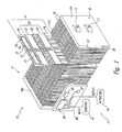
- FIG. 1 shows a portion of a fuel cell system 10, namely, a fuel cell stack 12 and an electronic fuel cell control system 14.
- Fuel cell stack 12 includes a number of fuel cell assemblies 16 arranged between a pair of end plates 18a, 18b, one of the fuel cell assemblies 16 being partially removed from fuel cell stack 12 to better illustrate the structure of fuel cell assembly 16.
- Tie rods extend between end plates 18a, 18b and cooperate with fastening nuts 17 to bias end plates 18a, 18b together by applying pressure to the various components to ensure good contact therebetween.
- Each fuel cell assembly 16 includes a membrane electrode assembly 20 including two electrodes, the anode 22 and the cathode 24, separated by an ion exchange membrane 26.
- Electrodes 22, 24 can be formed from a porous, electrically conductive sheet material, such as carbon fiber paper or cloth, that is permeable to the reactants.
- Each of electrodes 22, 24 is coated on a surface adjacent to ion exchange membrane 26 with a catalyst 27, such as a thin layer of platinum, to render each electrode electrochemically active.
- Fuel cell assembly 16 also includes a pair of separators or flow field plates 28 sandwiching membrane electrode assembly 20.
- each of flow field plates 28 includes one or more reactant passages 30 formed on a planar surface of flow field plate 28 adjacent an associated one of electrodes 22, 24 for carrying fuel to anode 22 and oxidant to cathode 24, respectively.
- Reactant passage 30 on only one of flow field plates 28 is visible in Figure 1 .
- Reactant passages 30 that carry the oxidant also carry exhaust air and product water away from cathode 24.
- fuel stack 12 is designed to operate in a closed fuel supply mode, thus substantially all of the hydrogen fuel supplied to it during operation is consumed, and little if any hydrogen is carried away from the stack 12 in normal operation of system 10.
- Each flow field plate 28 may include a plurality of cooling channels 32 formed on the planar surface of the flow field plate 28 opposite the planar surface having reactant passage 30.
- the cooling channels 32 of each adjacent fuel cell assembly 16 cooperate so that closed cooling channels 32 are formed between each membrane electrode assembly 20.
- Cooling channels 32 transmit a coolant fluid through fuel cell stack 12. Cooling channels 32 may be straight and parallel to each other, and traverse each plate 28 so that cooling channel inlets and outlets are located at respective edges of plate 28.
- the system may alternatively include a single bipolar flow field plate (not shown) between adjacent membrane electrode assemblies 20.
- a channel on one side of the bipolar plate carries fuel to the anode of one adjacent membrane electrode assembly 20, while a channel on the other side of the plate carries oxidant to the cathode of another adjacent membrane electrode assembly 20.
- additional flow field plates 28 having channels for carrying coolant e.g., liquid or gas, such as cooling air
- coolant e.g., liquid or gas, such as cooling air
- End plate 18a includes a fuel stream inlet port (not shown) for introducing a supply fuel stream into fuel cell stack 12.
- End plate 18b includes a fuel stream outlet port 35 for discharging an exhaust fuel stream from fuel cell stack 12 that comprises primarily water and non-reactive components and impurities.
- Fuel stream outlet port 35 is normally closed with a valve in closed fuel supply system operation.
- Each fuel cell assembly 16 has openings formed therein to cooperate with corresponding openings in adjacent assemblies 16 to form internal fuel supply and exhaust manifolds (not shown) that extend the length of stack 12.
- the fuel stream inlet port is fluidly connected to fluid outlet port 35 via respective reactant passages 30 that are in fluid communication with the fuel supply and exhaust manifolds, respectively.
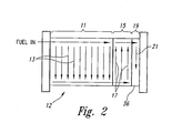
- Fuel flow through a final set 19 of two fuel cells assemblies 16 is in series with respect to the first and second sets 11, 15, and in a concurrent parallel direction within the set 19 (in a direction represented by arrow 21), generally opposite the flow of coolant through fuel cell stack 12.
- the oxidant is supplied to each of the fuel cells in parallel, in the same general direction as the flow of coolant through fuel cell stack 12.
- the system may comprise a second fuel cell stack which is dead-ended and which is downstream (with respect to the direction of reactant flow), and is fluidly connected to, fuel cell stack 12.
- fuel cell stack 12 may be dead-ended at a number of locations along reactant passages 30.
- some or all of the individual fuel cell assemblies 16 may be dead-ended or fuel cell stack 12 may be divided into a number of sections, each of which is supplied with fuel and is dead-ended separately.
- Each membrane electrode assembly 20 is designed to produce a nominal potential difference between anode 22 and cathode 24.
- Reactants hydrogen and air
- Hydrogen is supplied to electrodes 22, 24 on either side of ion exchange membrane 26 through reactant passages 30.
- Hydrogen is supplied to anode 22, where platinum catalyst 27 promotes its separation into protons and electrons, which pass as useful electricity through an external circuit (not shown).
- air flows through reactant passages 30 to cathode 24 where oxygen in the air reacts with protons passing through the ion exchange membrane 26 to produce product water.
- electronic control system 14 comprises various electrical and electronic components on a circuit board 38 and various sensors 44 and actuators 46 distributed throughout fuel cell system 10.
- Circuit board 38 carries a microprocessor or microcontroller 40 that is appropriately programmed or configured to carry out fuel cell system operation.
- Microcontroller 40 can take the form of an Atmel AVR RISC microcontroller available from Atmel Corporation of San Jose, California.
- Electronic control system 14 also includes a persistent memory 42, such as an EEPROM portion of microcontroller 40 or as a discrete nonvolatile controller-readable media.
- Microcontroller 40 is coupled to receive input from sensors 44 and to provide output to actuators 46.
- the input and/or output can take the form of either digital and/or analog signals.
- a rechargeable battery 47 powers the electronic control system 14 until fuel cell stack 12 can provide sufficient power to the electronic control system 14.
- Microcontroller 40 is selectively couplable between fuel cell stack 12 and battery 47 for switching power during fuel cell system operation and/or to recharge battery 47 during fuel cell operation.
- the nitrogen concentration gradient will be lessened, but the nitrogen concentration near the outlet of anode 22 may still be greater than the cathode nitrogen concentration.
- the concentration gradient may be substantially eliminated, but the nitrogen concentration in the anode flow field will equal the nitrogen concentration in the cathode flow field.
- Diffused nitrogen impedes the reaction at anode 22 (due to dilution of the fuel) and ultimately may cause the performance of the fuel cell assembly 16 to drop to an unacceptable level.
- the mol fraction of the nitrogen is well below the mol fraction of the fuel, and there is sufficient fuel (e.g., hydrogen) to sustain the anode reaction.
- the fuel is supplied at an overpressure (i.e. the fuel overpressure is equal to the difference between the fuel supply pressure and the oxidant supply pressure to the fuel cell assembly) of at least 34.47 KPa (5psig).
- Overpressures greater than 34.47 KPa (5psig) may also be of further benefit and may improve the performance and reliability of fuel cell system 10 for reasons in addition to overcoming nitrogen diffusion across membrane 26.
- increased fuel supply pressures are known to improve catalyst activity.
- the magnitude of the fuel overpressure to be used according to the present methods may be limited by the components and configuration of fuel cell system 10, particularly the tolerance of the seals and membrane 26 to increased fuel overpressure.
- Temperature and other operating conditions may be optimized for particular stack configurations. For example, by employing the present methods, it may be possible to operate fuel cell system 10 at higher operating temperatures than would be practical if fuel cell system 10 was to be operated without the present methods. Increased operating temperatures may improve the performance of fuel cell systems having a closed fuel supply system by improving water management at the anode.
- fuel is continuously supplied to stack 12 at an overpressure of greater than 34.47 KPa (5 psig).
- the fuel supply pressure may be varied, so that fuel is sometimes supplied at an overpressure of greater than 34.47 KPa (5psig) while at other times the fuel is not supplied at an overpressure of greater than 34.47 KPa(5 psig).
- the fuel overpressure may be varied between a 34.47 KPa(5 psig) overpressure and a greater overpressure.
- the variations may be of a constant frequency or intermittent (variable frequency), and may be either independent of or dependent on the transient operating conditions of fuel cell system 10.
- the overpressure may be varied at predetermined intervals from the start of operation.
- the use or the magnitude of fuel overpressure may be controlled by microcontroller 40 depending on the input received by sensors 44.
- sensors 44 monitor one or more parameters indicative of stack or cell performance, such as the voltage of one or more cells, to e.g. detect when fuel starvation is occurring.
- the use of or magnitude of overpressure may also be different during various operating phases of fuel cell system 10, such as during start-up or shut-down of fuel cell system 10.
- the use of or magnitude of overpressure may be varied depending on the load on or power output of fuel cell system 10, such as during no-load or partial load conditions.
- the overpressure may be lesser during no-load or partial load conditions than during full-load conditions.
- the rate of change of the load conditions may affect the desired overpressure, e.g. during transient conditions.
- system configurations described above such as systems which comprise a second fuel cell stack which is dead-ended or systems in which fuel cell stack 12 is dead-ended at a number of locations along the fuel flow path, may be employed to mitigate such effects.
- the non-reactive components will tend to accumulate in the second "dead-ended" fuel cell stack. In this way, the performance of the primary fuel cell stack will be preserved.
- fuel cell system 10 may be operated without the need for intermittent purges by maintaining the fuel supply pressure at a level sufficiently greater than the oxidant pressure.
- a purging system is not a required component of fuel cell system 10.
- fuel cell system 10 may include purging equipment.
- the final set 19 of fuel cell assemblies 16 in Figure 2 may comprise a purge cell portion of the fuel cell stack in which non-reactive components, including nitrogen, may be vented by opening a purge valve. (Although fuel cell stack 12 is designed to consume substantially all of the hydrogen fuel supplied to it during operation, traces of unreacted hydrogen may also be discharged through the fuel stream outlet port 35 ( Figure 1 ) during a purge of fuel cell stack 12.)
- purging may be used in conjunction with fuel overpressure.
- the purging system may be activated periodically, or as necessary, depending on system performance. See, for example, commonly assigned U.S. Patent Application Publication No. 2003/0022041 .
- overpressure may be used in conjunction with a continuous small bleed of the fuel stream from the anode side of fuel cell stack 12. See, for example, U.S. Patent Application Serial No. 10/253,390 .
- the bleed location(s) can be selected such that they are in the vicinity of where nitrogen is most likely to accumulate, such as where the stack and/or individual cell(s) are dead-ended, as discussed above.
- the cell voltage of the individual cells of a Ballard fuel cell stack (10 cells) was monitored.
- the stack was closed on the fuel side, and was operated at a coolant inlet temperature of about 70°C, with the fuel cell stack producing about 150 mA/cm 2 .
- Air was supplied to the stack as the oxidant at a constant pressure of approximately 68.95kPa(10 psig) a stoichiometry of approximately 1.8 and a relative humidity of approximately 73%. (Stoichiometry is the ratio of fuel or oxidant supplied to that consumed in the generation of electrical power in the fuel cell.)
- Substantially pure hydrogen was supplied to the stack at a stoichiometry of about 1.0 and a relative humidity of approximately 67%.
Landscapes
- Life Sciences & Earth Sciences (AREA)
- Engineering & Computer Science (AREA)
- Manufacturing & Machinery (AREA)
- Sustainable Development (AREA)
- Sustainable Energy (AREA)
- Chemical & Material Sciences (AREA)
- Chemical Kinetics & Catalysis (AREA)
- Electrochemistry (AREA)
- General Chemical & Material Sciences (AREA)
- Fuel Cell (AREA)
Description
- This application claims the benefit of
U.S. Provisional Patent Application 60/453,027 filed March 7, 2003 - The present invention relates to fuel cells and, more particularly, to methods of operating fuel cells having closed fuel supply systems.
- Electrochemical fuel cells convert fuel and oxidant to electricity. Solid polymer electrochemical fuel cells generally employ a membrane electrode assembly ("MEA") which comprises an ion exchange membrane or solid polymer electrolyte disposed between two electrodes typically comprising a layer of porous, electrically conductive sheet material, such as carbon fiber paper or carbon cloth. The MEA contains a layer of catalyst, typically in the form of finely comminuted platinum, at each membrane/electrode interface to induce the desired electrochemical reaction. In operation the electrodes are electrically coupled to provide a circuit for conducting electrons between the electrodes through an external circuit. Typically, a number of MEAs are serially coupled electrically to form a fuel cell stack having a desired power output.
- In typical fuel cells, the MEA is disposed between two electrically conductive fluid flow field plates or separator plates. Fluid flow field plates have at least one flow passage formed in at least one of the major planar surfaces thereof. The flow passages direct the fuel and oxidant to the respective electrodes, namely, the anode on the fuel side and the cathode on the oxidant side. The fluid flow field plates act as current collectors, provide support for the electrodes, provide access channels or passages for the fuel and oxidant to the respective anode and cathode surfaces, and provide passages for the removal of reaction products, such as water, formed during operation of the cell.
- Certain fuel cells are designed to operate in a closed mode on one or both reactants. Closed reactant supply systems include dead-ended configurations in which a reactant flow passage is generally closed, as well as systems employing closed-loop recirculation of the reactant exhaust stream from the fuel cell outlet to the fuel cell inlet and though the fuel cell with the addition of fresh reactant. In these situations the reactant used on the closed side is generally substantially pure. Typically a purge valve (which is normally closed in closed system operation) is provided somewhere in the reactant flow passage for periodic venting of accumulations of non-reactive components, which can build up in the reactant passages in closed system operation. In conventional fuel cell purge systems the purge valve is opened from time to time, for example, manually or at regular fixed time intervals. Alternatively a purge is triggered, for example, when the voltage or electrical output of one or more cells in a stack falls below a predetermined threshold value (see, for example,
GB Patent No. 1 223 941 US Patent No. 3,553,026 ), or after the fuel cell has expended a preselected number of ampere-hours (see, for example,US Patent No. 3,697,325 ). The reactant flow path through the fuel cell stack can be configured so that non-reactive components tend to accumulate first in just one or a few fuel cells of the stack, rather than in the outlet region of each cell in the stack. The purge system may be controlled via a controller (see, for example, commonly assignedU.S. Patent Application Publication No. 2003/0022041 ). -
US 6,117,577 discloses an ambient pressure fuel cell system provided with a fuel cell stack formed from a plurality of fuel cells having membrane/electrode assemblies (MEAs) that are hydrated with liquid water and bipolar plates with anode and cathode sides for distributing hydrogen fuel gas and water to a first side of each one of the MEAs and air with reactant oxygen gas to a second side of each one of the MEAs. A pump supplies liquid water to the fuel cells. A recirculating system may be used to return unused hydrogen fuel gas to the stack. A near-ambient pressure blower blows air through the fuel cell stack in excess of reaction stoichiometric amounts to react with the hydrogen fuel gas. -
US 6,451,470 discloses polymer electrolyte membrane fuel cells with modified gas diffusion electrodes which do not allow more water to escape than that formed during the reaction of burnable gas and oxidizing agent. -
US 6,479,177 discloses a method of ceasing operation of an electric power generation system involving purging one or more of the fuel cell stack oxidant and fuel passages at shutdown prior to allowing the fuel cell stack to drop to temperatures below the freezing point of water. Preferably purging at shutdown is conducted at a temperature below the stack operating temperature. - However, although purging can improve performance of fuel cells having closed reactant supply systems, it wastes valuable fuel and increases the parasitic load on the system since purging equipment is required. Furthermore, the release of hydrogen into the ambient environment may be undesirable. Accordingly, there remains a need for improved methods of operating fuel cells having closed reactant supply systems for which purging is not necessary.
- The present methods relate to fuel cells and, more particularly, to methods of operating fuel cells having closed fuel supply systems. Specifically, a method for operating a fuel cell system according to
independent claim 1 is provided. - In one embodiment, a method for operating a fuel cell system comprising at least one fuel cell stack, the stack comprising at least one fuel cell, the system further comprising a reactant supply system, the reactant supply system comprising a fuel passage for directing a fuel stream through the stack and an oxidant passage for directing an oxidant stream through the stack, the method comprising supplying the oxidant stream to the oxidant passage at an oxidant supply pressure; and supplying the fuel stream to the fuel passage at a fuel supply pressure; wherein the fuel supply pressure is at least 34.47 kPa (5 psig) greater than the oxidant supply pressure at least some of the time and a fuel side of the reactant supply system is closed at least some of the time.
- In some embodiments, the fuel cell may be a solid polymer electrolyte fuel cell, and the reactant streams hydrogen and air.
- In some embodiments, during operation the fuel supply pressure is always at least 34.47 kPa (5 psig) greater than the oxidant supply pressure, and may be between about 34.47 kPa (5 psig) and 206.84 KPa (30 psig) greater than the oxidant supply pressure. In other embodiments, the fuel supply pressure may be intermittently at least 34.47 kPa (5 psig) greater than the oxidant supply pressure. In still other embodiments, the fuel supply pressure is at least 34.47 kPa (5 psig) greater than the oxidant supply pressure when the fuel side of the reactant supply system is closed.
- In some embodiments, the fuel supply pressure may be varied, and the variation may be at a substantially constant frequency, or based on the power output fuel cell system, or based on a parameter indicative of fuel cell performance. In other embodiments, the fuel supply pressure may be varied during different operational phases, such as during shut-down and/or start-up of the fuel cell system.
- In some embodiments, the fuel side of the reactant supply system is always closed, such as by having a fuel side of at least one fuel cell dead-ended. In other embodiments, the fuel side of the reactant supply system comprises a recirculation loop for recirculating the fuel stream through the stack. In still other embodiments, the fuel side of the reactant supply system comprises a purge valve which may be periodically opened to discharge a portion of the fuel stream from the stack. In still other embodiments, the fuel side of the reactant supply system may be closed at a plurality of locations, such as having the fuel side of each fuel cell dead-ended. In still further embodiments, the fuel cell system comprises a primary stack and a secondary stack fluidly connected to receive the fuel stream in series downstream of the primary stack, wherein a fuel passage of the secondary stack is dead-ended at least some of the time.
- These and other aspects of the present methods will be apparent upon reference to the attached figures and following detailed description.
- In the figures, identical reference numbers identify similar elements or acts. The sizes and relative positions of elements in the figures are not necessarily drawn to scale. For example, the shapes of various elements and angles are not drawn to scale, and some of these elements are arbitrarily enlarged and positioned to improve figure legibility. Further, the particular shapes of the elements, as drawn, are not intended to convey any information regarding the actual shape of the particular elements, and have been solely selected for ease of recognition in the figures.
-
Figure 1 is an isometric, partially exploded, view of a fuel cell system including a fuel cell stack and controlling electronics. -
Figure 2 is a schematic diagram representing fuel flow through a cascaded fuel cell stack of the fuel cell system ofFigure 1 . -
Figure 3 is a graph showing the cell voltage over time for a fuel cell stack operated with fuel overpressures from 0 to 7 kPa (0 to 30 psi). -
Figure 4 is a graph showing the voltage of the individual cells as well as the stack voltage versus the fuel overpressure. -
Figure 5 is a graph showing the average cell voltage of the fuel cells of a fuel cell stack operated with fuel overpressure according to one embodiment of the present methods. - In the following detailed description, certain specific details are set forth in order to provide a thorough understanding of various embodiments of the invention. However, one skilled in the art will understand that the invention may be practiced without these details. In other instances, well known structures associated with fuel cell stacks and fuel cell systems have not been described in detail to avoid unnecessarily obscuring the descriptions of the embodiments of the invention.
- Unless the context requires otherwise, throughout the specification and claims which follow, the word "comprise" and variations thereof, such as "comprises" and "comprising" are to be construed in an open, inclusive sense, that is as "including but not limited to".
-
Figure 1 shows a portion of afuel cell system 10, namely, afuel cell stack 12 and an electronic fuelcell control system 14.Fuel cell stack 12 includes a number offuel cell assemblies 16 arranged between a pair ofend plates fuel cell assemblies 16 being partially removed fromfuel cell stack 12 to better illustrate the structure offuel cell assembly 16. Tie rods (not shown) extend betweenend plates fastening nuts 17 to biasend plates - Each
fuel cell assembly 16 includes amembrane electrode assembly 20 including two electrodes, theanode 22 and thecathode 24, separated by anion exchange membrane 26.Electrodes electrodes ion exchange membrane 26 with acatalyst 27, such as a thin layer of platinum, to render each electrode electrochemically active. -
Fuel cell assembly 16 also includes a pair of separators or flowfield plates 28 sandwichingmembrane electrode assembly 20. In the illustrated embodiment, each offlow field plates 28 includes one ormore reactant passages 30 formed on a planar surface offlow field plate 28 adjacent an associated one ofelectrodes anode 22 and oxidant tocathode 24, respectively. (Reactant passage 30 on only one offlow field plates 28 is visible inFigure 1 .)Reactant passages 30 that carry the oxidant also carry exhaust air and product water away fromcathode 24. As will be described in more detail below,fuel stack 12 is designed to operate in a closed fuel supply mode, thus substantially all of the hydrogen fuel supplied to it during operation is consumed, and little if any hydrogen is carried away from thestack 12 in normal operation ofsystem 10. - Each
flow field plate 28 may include a plurality ofcooling channels 32 formed on the planar surface of theflow field plate 28 opposite the planar surface havingreactant passage 30. When the stack is assembled, the coolingchannels 32 of each adjacentfuel cell assembly 16 cooperate so thatclosed cooling channels 32 are formed between eachmembrane electrode assembly 20.Cooling channels 32 transmit a coolant fluid throughfuel cell stack 12.Cooling channels 32 may be straight and parallel to each other, and traverse eachplate 28 so that cooling channel inlets and outlets are located at respective edges ofplate 28. - While the illustrated fuel cell system includes two
flow field plates 28 in eachfuel cell assembly 16, the system may alternatively include a single bipolar flow field plate (not shown) between adjacentmembrane electrode assemblies 20. In such systems, a channel on one side of the bipolar plate carries fuel to the anode of one adjacentmembrane electrode assembly 20, while a channel on the other side of the plate carries oxidant to the cathode of another adjacentmembrane electrode assembly 20. In such systems, additionalflow field plates 28 having channels for carrying coolant (e.g., liquid or gas, such as cooling air) can be spaced throughoutfuel cell stack 12, as needed to provide sufficient cooling ofstack 12. -
End plate 18a includes a fuel stream inlet port (not shown) for introducing a supply fuel stream intofuel cell stack 12.End plate 18b includes a fuelstream outlet port 35 for discharging an exhaust fuel stream fromfuel cell stack 12 that comprises primarily water and non-reactive components and impurities. Fuelstream outlet port 35 is normally closed with a valve in closed fuel supply system operation. - Each
fuel cell assembly 16 has openings formed therein to cooperate with corresponding openings inadjacent assemblies 16 to form internal fuel supply and exhaust manifolds (not shown) that extend the length ofstack 12. The fuel stream inlet port is fluidly connected tofluid outlet port 35 viarespective reactant passages 30 that are in fluid communication with the fuel supply and exhaust manifolds, respectively. -
End plate 18b includes an oxidantstream inlet port 37 for introducing supply air (oxidant stream) intofuel cell stack 12, and an oxidantstream outlet port 39 for discharging exhaust air fromfuel cell stack 12. Eachfuel cell assembly 16 hasopenings fuel cell assemblies 16 to form oxidant supply and exhaust manifolds that extend the length ofstack 12.Oxidant inlet port 37 is fluidly connected to theoxidant outlet port 39 viarespective reactant passages 30 that are in fluid communication with oxidant supply and exhaust manifolds, respectively. - As shown in
Figure 2 , fuel may be directed throughfuel cell stack 12 in a cascaded flow pattern. Afirst set 11 offuel cell assemblies 16 are arranged so that fuel flows within the set in a concurrent parallel direction (represented by arrows 13) that is generally opposite the direction of the flow of coolant throughfuel cell stack 12. Fuel flow through anext set 15 of twofuel cell assemblies 16 is in series with respect to the flow of fuel in thefirst set 11, and in a concurrent parallel direction within the set 15 (in a direction represented by arrows 17) that is generally concurrent with the direction of the flow of coolant throughfuel cell stack 12. Fuel flow through afinal set 19 of twofuel cells assemblies 16 is in series with respect to the first andsecond sets fuel cell stack 12. The oxidant is supplied to each of the fuel cells in parallel, in the same general direction as the flow of coolant throughfuel cell stack 12. - In an alternate configuration, rather than "dead-ending"
fuel cell stack 12, the system may comprise a second fuel cell stack which is dead-ended and which is downstream (with respect to the direction of reactant flow), and is fluidly connected to,fuel cell stack 12. In yet another alternate configuration, rather than dead-endingfuel cell stack 12 at one location (e.g., by closing fuel outlet port 35) as shown inFigure 1 ,fuel cell stack 12 may be dead-ended at a number of locations alongreactant passages 30. For example, some or all of the individualfuel cell assemblies 16 may be dead-ended orfuel cell stack 12 may be divided into a number of sections, each of which is supplied with fuel and is dead-ended separately. - Each
membrane electrode assembly 20 is designed to produce a nominal potential difference betweenanode 22 andcathode 24. Reactants (hydrogen and air) are supplied toelectrodes ion exchange membrane 26 throughreactant passages 30. Hydrogen is supplied toanode 22, whereplatinum catalyst 27 promotes its separation into protons and electrons, which pass as useful electricity through an external circuit (not shown). On the opposite side ofmembrane electrode assembly 20, air flows throughreactant passages 30 tocathode 24 where oxygen in the air reacts with protons passing through theion exchange membrane 26 to produce product water. - With continuing reference to
Figure 1 ,electronic control system 14 comprises various electrical and electronic components on acircuit board 38 and various sensors 44 andactuators 46 distributed throughoutfuel cell system 10.Circuit board 38 carries a microprocessor ormicrocontroller 40 that is appropriately programmed or configured to carry out fuel cell system operation.Microcontroller 40 can take the form of an Atmel AVR RISC microcontroller available from Atmel Corporation of San Jose, California.Electronic control system 14 also includes apersistent memory 42, such as an EEPROM portion ofmicrocontroller 40 or as a discrete nonvolatile controller-readable media. -
Microcontroller 40 is coupled to receive input from sensors 44 and to provide output to actuators 46. The input and/or output can take the form of either digital and/or analog signals. A rechargeable battery 47 powers theelectronic control system 14 untilfuel cell stack 12 can provide sufficient power to theelectronic control system 14.Microcontroller 40 is selectively couplable betweenfuel cell stack 12 and battery 47 for switching power during fuel cell system operation and/or to recharge battery 47 during fuel cell operation. - Without being bound by theory, the conditions existing in
fuel cell assembly 16 operating on air and having a closed fuel supply are described. Assuming steady state conditions, there is no net diffusion of nitrogen acrossmembrane 26. Nearanode inlet 12 the mol fraction of nitrogen in the fuel stream is low as a relatively small amount of nitrogen diffuses acrossmembrane 26 and enters the fuel passages. As fuel is consumed along the length ofanode 22 the mol fraction of nitrogen increases. Due to convective mass flow of nitrogen and the consumption of fuel infuel cell assembly 16, the mol fraction of nitrogen near the outlet ofanode 22 may be greater than the mol fraction of nitrogen incathode 24, in which case nitrogen will back-diffuse acrossmembrane 26 to the cathode side. At steady state the integral of the nitrogen concentration gradient across the membrane times the cell area over the inlet of the cell (driving diffusion from cathode to anode) equals the integral of the corresponding nitrogen concentration gradient times the cell area over the outlet of the cell (driving diffusion from anode to cathode). - In a dead-ended system without anode exhaust recycling, the mol fraction of nitrogen near the outlet of
anode 22 will exceed the mol fraction of nitrogen in air. Thus, a nitrogen concentration gradient will exist inanode 22. The magnitude of the concentration gradient is affected by factors including the fuel velocity in the anode flow field and the fuel stoichiometry. Increasing the fuel velocity inanode 22 will increase the convective mass flow of nitrogen toward the outlet ofanode 22, increasing the concentration gradient. Fuel velocity increases with factors such as the pressure drop associated withanode 22, increased operating pressure offuel cell assembly 16 and high loads. Decreasing the fuel stoichiometry also increases the nitrogen concentration gradient. Indeed, at a fuel stoichiometry of 1, essentially all of the fuel inanode 22 is consumed and the mol faction of nitrogen near the outlet ofanode 22 approaches unity. - If the anode exhaust is recycled periodically, or a portion of the exhaust is recycled, then the nitrogen concentration gradient will be lessened, but the nitrogen concentration near the outlet of
anode 22 may still be greater than the cathode nitrogen concentration. With continuous recycle of the anode exhaust, the concentration gradient may be substantially eliminated, but the nitrogen concentration in the anode flow field will equal the nitrogen concentration in the cathode flow field. - Diffused nitrogen impedes the reaction at anode 22 (due to dilution of the fuel) and ultimately may cause the performance of the
fuel cell assembly 16 to drop to an unacceptable level. - By maintaining the fuel supply pressure at a sufficiently high level according to the present methods, the mol fraction of the nitrogen is well below the mol fraction of the fuel, and there is sufficient fuel (e.g., hydrogen) to sustain the anode reaction. According to the present methods, during at least some periods of operation the fuel is supplied at an overpressure (i.e. the fuel overpressure is equal to the difference between the fuel supply pressure and the oxidant supply pressure to the fuel cell assembly) of at least 34.47 KPa (5psig). Overpressures greater than 34.47 KPa (5psig) may also be of further benefit and may improve the performance and reliability of
fuel cell system 10 for reasons in addition to overcoming nitrogen diffusion acrossmembrane 26. For example, increased fuel supply pressures are known to improve catalyst activity. The magnitude of the fuel overpressure to be used according to the present methods may be limited by the components and configuration offuel cell system 10, particularly the tolerance of the seals andmembrane 26 to increased fuel overpressure. - Temperature and other operating conditions may be optimized for particular stack configurations. For example, by employing the present methods, it may be possible to operate
fuel cell system 10 at higher operating temperatures than would be practical iffuel cell system 10 was to be operated without the present methods. Increased operating temperatures may improve the performance of fuel cell systems having a closed fuel supply system by improving water management at the anode. - While the foregoing discussion has been related to the diffusion of nitrogen into the anode space of fuel cells, it is understood that the same principles apply in respect of other inert or non-reactive components present in the oxidant stream that diffuse across the fuel cell membrane.
- In one embodiment of the present methods, fuel is continuously supplied to stack 12 at an overpressure of greater than 34.47 KPa (5 psig). In other embodiments, the fuel supply pressure may be varied, so that fuel is sometimes supplied at an overpressure of greater than 34.47 KPa (5psig) while at other times the fuel is not supplied at an overpressure of greater than 34.47 KPa(5 psig). In still other embodiments, the fuel overpressure may be varied between a 34.47 KPa(5 psig) overpressure and a greater overpressure. The variations may be of a constant frequency or intermittent (variable frequency), and may be either independent of or dependent on the transient operating conditions of
fuel cell system 10. For example, the overpressure may be varied at predetermined intervals from the start of operation. In another embodiment, the use or the magnitude of fuel overpressure may be controlled bymicrocontroller 40 depending on the input received by sensors 44. In one embodiment, sensors 44 monitor one or more parameters indicative of stack or cell performance, such as the voltage of one or more cells, to e.g. detect when fuel starvation is occurring. Similarly, the use of or magnitude of overpressure may also be different during various operating phases offuel cell system 10, such as during start-up or shut-down offuel cell system 10. Similarly, the use of or magnitude of overpressure may be varied depending on the load on or power output offuel cell system 10, such as during no-load or partial load conditions. For example, the overpressure may be lesser during no-load or partial load conditions than during full-load conditions. In addition, the rate of change of the load conditions may affect the desired overpressure, e.g. during transient conditions. - As discussed above, due to the flow of fuel through the fuel passages as the fuel is consumed, the non-reactive components tend to accumulate near the location(s) where
fuel cell stack 12 is dead-ended. This may lead to unacceptable performance of thefuel cell assemblies 16 in the location. Accordingly, in further alternate embodiments, system configurations described above, such as systems which comprise a second fuel cell stack which is dead-ended or systems in whichfuel cell stack 12 is dead-ended at a number of locations along the fuel flow path, may be employed to mitigate such effects. For example, in a system comprising a second fuel cell stack, which is dead-ended and which is fluidly connected downstream (with respect to the direction of reactant flow) to the primary fuel cell stack, the non-reactive components will tend to accumulate in the second "dead-ended" fuel cell stack. In this way, the performance of the primary fuel cell stack will be preserved. - As described above, according to the present methods,
fuel cell system 10 may be operated without the need for intermittent purges by maintaining the fuel supply pressure at a level sufficiently greater than the oxidant pressure. Thus, a purging system is not a required component offuel cell system 10. However, it may be desirable forfuel cell system 10 to retain the ability to purge, and accordingly, in alternate embodiments,fuel cell system 10 may include purging equipment. For example, thefinal set 19 offuel cell assemblies 16 inFigure 2 may comprise a purge cell portion of the fuel cell stack in which non-reactive components, including nitrogen, may be vented by opening a purge valve. (Althoughfuel cell stack 12 is designed to consume substantially all of the hydrogen fuel supplied to it during operation, traces of unreacted hydrogen may also be discharged through the fuel stream outlet port 35 (Figure 1 ) during a purge offuel cell stack 12.) - Accordingly, in some embodiments of the present methods, purging may be used in conjunction with fuel overpressure. For example, the purging system may be activated periodically, or as necessary, depending on system performance. See, for example, commonly assigned
U.S. Patent Application Publication No. 2003/0022041 . In yet another embodiment of the present methods, overpressure may be used in conjunction with a continuous small bleed of the fuel stream from the anode side offuel cell stack 12. See, for example,U.S. Patent Application Serial No. 10/253,390 . The bleed location(s) can be selected such that they are in the vicinity of where nitrogen is most likely to accumulate, such as where the stack and/or individual cell(s) are dead-ended, as discussed above. - The following examples have been included to illustrate different embodiments and aspects of the present methods but they should not be construed as limiting in any way.
- The cell voltage of the individual cells of a Ballard fuel cell stack (10 cells) was monitored. The stack was closed on the fuel side, and was operated at a coolant inlet temperature of about 70°C, with the fuel cell stack producing about 150 mA/cm2. Air was supplied to the stack as the oxidant at a constant pressure of approximately 68.95kPa(10 psig) a stoichiometry of approximately 1.8 and a relative humidity of approximately 73%. (Stoichiometry is the ratio of fuel or oxidant supplied to that consumed in the generation of electrical power in the fuel cell.) Substantially pure hydrogen was supplied to the stack at a stoichiometry of about 1.0 and a relative humidity of approximately 67%. The pressure of the hydrogen supplied was varied from about 68.95kPa (10psig) (fuel overpressure ≈ 0 kPA (0 psig)) to about 275.80kPa (40 psig) (fuel overpressure ≈206.84 kPa (30 psig)). The stack was not purged during the test period.
-
Figure 3 shows the voltage of the individual cells over time as the fuel overpressure was varied. As shown inFigure 3 , the stack operated continuously, without the need for fuel purges, for approximately 2 hours so long as the fuel pressure was at least 34.47kPa (5psig) greater than the oxidant pressure (time = 0 to time =120 minutes). As can be seen fromFigure 3 , although the voltage of half of the cells was lower than the others during that period, the performance of the lower voltage cells was nonetheless stable. However, once the fuel overpressure was reduced below about 34.47kPa (5psig) the performance of some of the cells started to drop significantly. -
Figure 4 is an extract from theFigure 3 data, showing the voltage of the individual cells and the stack at the various fuel overpressures. Again, as can be seen from the figure, the cells were able to operate without any stack purging when the fuel overpressure was greater than about 34.47kPa (5psig). Their performance began to drop significantly once the fuel overpressure was reduced below 34.47kPa (5 psig). - The cell voltage of a 47 fuel cell NEXA™ stack was monitored. The stack was closed on the fuel side, and was operated at a coolant inlet temperature of about 65°C, with the fuel cell stack producing about 432 mA/cm2. Air was supplied to the stack as the oxidant at a constant pressure of approximately 15.51 kPa (2.25 psig) a stoichiometry of approximately 2.0 and a relative humidity of approximately 90-95%. Substantially pure unhumidified hydrogen was supplied to the stack at a pressure of approximately 98.25 kPa (14.25 psig) and a stoichiometry of about 1.0 (fuel overpressure ≈82,74 kPa (12 psig)). After approximately 64 hours, the coolant inlet temperature was increased to about 75°C and the stack was operated for approximately 2 additional hours, after which the test was stopped. The stack was not purged during the test period.
-
Figure 5 shows the average cell voltage over time during the above test period (i.e. closed fuel side operation with substantially constant fuel overpressure). As shown inFigure 5 , the stack operated continuously, without the need for fuel purges, for over 63 hours at a coolant inlet temperature of 65°C, and an additional 2 hours at a coolant inlet temperature of 75°C. As can be seen fromFigure 5 , increasing the coolant inlet temperature improved the average cell voltage. - It can be advantageous to use the above described methods, involving use of a fuel overpressure, in fuel cell systems that are dead-ended on the fuel side but have a fuel recirculation loop. In such configurations the accumulation of nitrogen and non-reactive components on the anode side (in the fuel loop) can be mitigated by use of a fuel overpressure.
- The various embodiments described above can be combined to provide further embodiments. The described methods can omit some acts and can add other acts, and can execute the acts in a different order than that illustrated, to achieve the advantages of the invention.
- These and other changes can be made to the invention in light of the above detailed description. In general, in the following claims, the terms used should not be construed to limit the invention to the specific embodiments disclosed in the specification, but should be construed to include all fuel cell systems, controllers and processors, actuators, and sensors that operate in accordance with the claims. Accordingly, the invention is not limited by the disclosure, but instead its scope is to be determined entirely by the following claims.
Claims (20)
- A method for operating a fuel cell system (10) comprising at least one fuel cell stack (12), the stack (12) comprising at least one fuel cell (16), the fuel cell system (10) further comprising a reactant supply system, the reactant supply system comprising a fuel passage (30) for directing a fuel stream through the stack (12) and an oxidant passage (30) for directing an oxidant stream through the stack, the method comprising:supplying the oxidant stream to the oxidant passage (30) at an oxidant supply pressure; and
supplying the fuel stream to the fuel passage (30) at a fuel supply pressure;wherein the fuel supply pressure is at least 34,47 kPa (5 psig) greater than the oxidant supply pressure at least some of the time and a fuel side of the reactant supply system is closed at least some of the time;characterized in that the fuel supply pressure is at least 34,47 kPa (5 psig) greater than the oxidant supply pressure when the fuel side of the reactant supply system is closed. - The method of claim 1,
wherein the at least one fuel cell (16) is a solid polymer electrolyte fuel cell. - The method of claim 2,
wherein the fuel stream is hydrogen and the oxidant stream is air. - The method of claim 1,
wherein during operation the fuel supply pressure is always at least 34,4 kPa (5 psig) greater than the oxidant supply pressure. - The method of claim 4,
further comprising: varying the fuel supply pressure. - The method of claim 1,
further comprising: varying the fuel supply pressure, wherein the fuel supply pressure is intermittently at least 34,47 kPa (5 psig) greater than the oxidant supply pressure. - The method of claim 5 or 6,
wherein the fuel supply pressure is varied at a substantially constant frequency. - The method of claim 5,
wherein the fuel supply pressure is at least 34,47 kPa (5 psig) greater than the oxidant supply pressure during at least one of a shut-down phase and a start-up phase of the fuel cell system (10). - The method of claim 5 or 6,
wherein the fuel supply pressure is varied based on the power output of the fuel cell system (10). - The method of claim 5 or 6,
wherein the fuel cell system (10) further comprises at least one sensor (44), and varying the fuel supply pressure comprises varying the fuel supply pressure based on an output of the sensor (44). - The method of claim 5 or 6, further comprising:monitoring a parameter indicative of fuel cell performance, wherein the fuel supply pressure is varied based on the parameter indicative of fuel cell performance.
- The method of claim 1,
wherein the fuel side of the reactant supply system is always closed. - The method of claim 1,
wherein the fuel side of the reactant supply system comprises a purge valve which is periodically opened to discharge a portion of the fuel stream from the stack (12). - The method of claim 1 or 13,
wherein the fuel side of the reactant supply system further comprises a recirculation loop and the method further comprises recirculating the fuel stream through the stack (12). - The method of claim 1,
wherein the fuel side of the reactant supply system is closed at a plurality of locations. - The method of claim 1,
wherein the stack comprises a plurality of fuel cells (16), and a fuel side of at least one fuel cell (16) is dead-ended. - The method of claim 16,
wherein the fuel side of each fuel cell (16) is dead- ended. - The method of claim 1,
wherein the fuel cell system (10) comprises a primary stack (16) and a secondary stack (16) fluidly connected to receive the fuel stream in series downstream of the primary stack (16), wherein a fuel passage (30) of the secondary stack (16) is dead-ended at least some of the time. - The method of claim 1,
wherein the fuel supply pressure is between about 34,47 kPa (5 psig) and 206,84 kPa (30 psig) greater than the oxidant supply pressure. - The method of claim 1,
wherein the fuel supply pressure is at least 68,95 kPa (10 psig) greater than the oxidant supply pressure.
Applications Claiming Priority (3)
| Application Number | Priority Date | Filing Date | Title |
|---|---|---|---|
| US45302703P | 2003-03-07 | 2003-03-07 | |
| US453027P | 2003-03-07 | ||
| PCT/CA2004/000334 WO2004079845A2 (en) | 2003-03-07 | 2004-03-05 | Methods of operating fuel cells having closed reactant supply systems |
Publications (2)
| Publication Number | Publication Date |
|---|---|
| EP1604418A2 EP1604418A2 (en) | 2005-12-14 |
| EP1604418B1 true EP1604418B1 (en) | 2015-01-28 |
Family
ID=32962753
Family Applications (1)
| Application Number | Title | Priority Date | Filing Date |
|---|---|---|---|
| EP04717531.0A Expired - Lifetime EP1604418B1 (en) | 2003-03-07 | 2004-03-05 | Methods of operating fuel cells having closed reactant supply systems |
Country Status (6)
| Country | Link |
|---|---|
| US (1) | US7153598B2 (en) |
| EP (1) | EP1604418B1 (en) |
| JP (1) | JP5129479B2 (en) |
| CN (1) | CN100446321C (en) |
| CA (1) | CA2518364C (en) |
| WO (1) | WO2004079845A2 (en) |
Families Citing this family (22)
| Publication number | Priority date | Publication date | Assignee | Title |
|---|---|---|---|---|
| KR101127028B1 (en) | 2003-11-19 | 2012-03-26 | 아쿠아훼아리 가부시키가이샤 | Fuel cell |
| WO2006038519A1 (en) * | 2004-10-05 | 2006-04-13 | Nitto Denko Corporation | Fuel cell and power generating method |
| EP1653545B1 (en) * | 2004-11-02 | 2007-02-21 | Siemens Aktiengesellschaft | Process of running a fuel cell stack and the stack itself |
| WO2006077477A2 (en) * | 2005-01-18 | 2006-07-27 | Ird Fuel Cells A/S | Fuel cell stacks and methods for controlling fuel gas flow to different sections of fuel cell stacks |
| JP4788945B2 (en) * | 2005-04-06 | 2011-10-05 | トヨタ自動車株式会社 | Fuel cell system |
| WO2007085096A1 (en) * | 2006-01-25 | 2007-08-02 | Angstrom Power Inc. | Method for operating fuel cells with passive reactant supply |
| JP2007242266A (en) * | 2006-03-06 | 2007-09-20 | Canon Inc | Fuel cell device, and operation method of fuel cell |
| WO2007119621A1 (en) * | 2006-04-11 | 2007-10-25 | Toyota Jidosha Kabushiki Kaisha | Fuel cell system |
| JP5164342B2 (en) | 2006-05-29 | 2013-03-21 | キヤノン株式会社 | Fuel cell device |
| US20100040914A1 (en) * | 2006-12-29 | 2010-02-18 | Sitaram Ramaswamy | Fuel-cascaded fuel cell stacks with decoupled power outputs |
| JP5125141B2 (en) * | 2007-02-21 | 2013-01-23 | トヨタ自動車株式会社 | Fuel cell system |
| JP5029069B2 (en) * | 2007-03-01 | 2012-09-19 | トヨタ自動車株式会社 | Device for estimating concentration distribution of impurities in anode and fuel cell system using the same |
| WO2008153073A1 (en) * | 2007-06-11 | 2008-12-18 | Ngk Spark Plug Co., Ltd. | Solid state electrolyte fuel cell module |
| JP2008311047A (en) * | 2007-06-14 | 2008-12-25 | Toyota Motor Corp | Fuel cell |
| WO2010058747A1 (en) * | 2008-11-21 | 2010-05-27 | 日産自動車株式会社 | Fuel cell system and method for controlling same |
| DE102010030152A1 (en) * | 2010-06-16 | 2011-12-22 | Robert Bosch Gmbh | Method for ensuring supply of fuel to anode of fuel cell, involves increasing partial pressure of fuel at anode so that pressure at anode and cathode is equalized if supply of fuel to anode is insufficient due to accumulation of inert gas |
| KR101417345B1 (en) * | 2012-09-19 | 2014-07-08 | 기아자동차주식회사 | Control method for fuel cell system |
| US20140242476A1 (en) * | 2013-02-28 | 2014-08-28 | Michael Kühne | Operating battery stack system performance by alternating the flow of heat carrying fluid used therein |
| CN103311558B (en) * | 2013-05-30 | 2015-09-30 | 中国科学院宁波材料技术与工程研究所 | Galvanic pile array in a kind of solid oxide fuel cell power generating system |
| WO2018183047A1 (en) | 2017-03-29 | 2018-10-04 | Ballard Power Systems Inc. | Flow field plate for an electrochemical fuel cell |
| US11742503B2 (en) * | 2018-11-07 | 2023-08-29 | Ballard Power Systems Inc. | Method and system for operating an electrochemical fuel cell stack with improved performance recovery |
| US20210135256A1 (en) * | 2019-11-06 | 2021-05-06 | GM Global Technology Operations LLC | Process and system for anode overpressure remedial action in a fuel cell system |
Family Cites Families (27)
| Publication number | Priority date | Publication date | Assignee | Title |
|---|---|---|---|---|
| DE1596311C2 (en) | 1966-12-14 | 1971-05-27 | Varta Ag | Process for the condensation of water of reaction in the gas cycle and for the discharge of the inert gases in a fuel battery |
| FR1595430A (en) | 1968-03-15 | 1970-06-08 | ||
| US3775282A (en) | 1968-08-29 | 1973-11-27 | Gen Electric | Electro-chemical ion exchange membrane purge pump |
| US3615842A (en) | 1968-08-29 | 1971-10-26 | Gen Electric | Method and apparatus comprising an electrochemical ion exchange membrane purge pump in combination and fuel cell combination |
| US3697325A (en) | 1969-08-21 | 1972-10-10 | Isotopes Inc | Purge control for fuel cell |
| US4769297A (en) | 1987-11-16 | 1988-09-06 | International Fuel Cells Corporation | Solid polymer electrolyte fuel cell stack water management system |
| US5366818A (en) | 1991-01-15 | 1994-11-22 | Ballard Power Systems Inc. | Solid polymer fuel cell systems incorporating water removal at the anode |
| US5260143A (en) | 1991-01-15 | 1993-11-09 | Ballard Power Systems Inc. | Method and apparatus for removing water from electrochemical fuel cells |
| EP0596366B1 (en) | 1992-11-05 | 1997-04-23 | Siemens Aktiengesellschaft | Method and device for removing water and inert gases from a fuel-cell battery |
| US5441821A (en) * | 1994-12-23 | 1995-08-15 | Ballard Power Systems Inc. | Electrochemical fuel cell system with a regulated vacuum ejector for recirculation of the fluid fuel stream |
| US5879826A (en) * | 1995-07-05 | 1999-03-09 | Humboldt State University Foundation | Proton exchange membrane fuel cell |
| US6479177B1 (en) | 1996-06-07 | 2002-11-12 | Ballard Power Systems Inc. | Method for improving the cold starting capability of an electrochemical fuel cell |
| DE19709199A1 (en) * | 1997-03-06 | 1998-09-17 | Magnet Motor Gmbh | Gas diffusion electrode with reduced diffusivity for water and method for operating a polymer electrolyte membrane fuel cell without supplying membrane dampening water |
| JPH117970A (en) * | 1997-06-18 | 1999-01-12 | Mitsubishi Electric Corp | Medium and large capacity fuel cell power generator |
| JP2001513940A (en) * | 1998-03-06 | 2001-09-04 | マグネート−モートア、ゲゼルシャフト、フュール、マグネートモートリシェ、テヒニク、ミット、ベシュレンクテル、ハフツング | Gas diffusion electrode and polymer electrolyte membrane fuel cell with low water diffusion capacity |
| US6117577A (en) | 1998-08-18 | 2000-09-12 | Regents Of The University Of California | Ambient pressure fuel cell system |
| US6124054A (en) | 1998-12-23 | 2000-09-26 | International Fuel Cells, Llc | Purged anode low effluent fuel cell |
| US6423434B1 (en) | 1999-08-09 | 2002-07-23 | Motorola, Inc. | Method and apparatus for managing fuel cell performance |
| JP3475869B2 (en) * | 1999-09-17 | 2003-12-10 | 松下電器産業株式会社 | Polymer electrolyte fuel cell and method for recovering its characteristics |
| US6461751B1 (en) | 1999-12-06 | 2002-10-08 | Ballard Power Systems Inc. | Method and apparatus for operating a fuel cell |
| US6426158B1 (en) | 2000-07-20 | 2002-07-30 | Motorola, Inc. | Method of diluting hydrogen gas exhausted from a fuel cell |
| JP3634253B2 (en) * | 2000-09-13 | 2005-03-30 | 本田技研工業株式会社 | Fuel cell system and control method thereof |
| FR2816761B1 (en) | 2000-11-14 | 2003-01-24 | Air Liquide | PROCESS AND INSTALLATION FOR PURGING WATER INCLUDED IN THE HYDROGEN CIRCUIT OF A FUEL CELL |
| CA2379363A1 (en) | 2001-03-28 | 2002-09-28 | Ballard Power Systems Inc. | Methods and apparatus for improving the cold starting capability of a fuel cell |
| US6960401B2 (en) * | 2001-07-25 | 2005-11-01 | Ballard Power Systems Inc. | Fuel cell purging method and apparatus |
| EP1296402A1 (en) | 2001-09-25 | 2003-03-26 | Ballard Power Systems AG | Fuel cell system and method for operating the same |
| US6926981B2 (en) * | 2001-11-28 | 2005-08-09 | Ballard Power Systems Inc. | Fuel cell system for operation at pressures below the pressure of the surrounding environment and method of operation thereof |
-
2004
- 2004-03-05 US US10/795,114 patent/US7153598B2/en not_active Expired - Lifetime
- 2004-03-05 CA CA2518364A patent/CA2518364C/en not_active Expired - Lifetime
- 2004-03-05 WO PCT/CA2004/000334 patent/WO2004079845A2/en not_active Ceased
- 2004-03-05 JP JP2006504069A patent/JP5129479B2/en not_active Expired - Lifetime
- 2004-03-05 EP EP04717531.0A patent/EP1604418B1/en not_active Expired - Lifetime
- 2004-03-05 CN CNB2004800112251A patent/CN100446321C/en not_active Expired - Lifetime
Also Published As
| Publication number | Publication date |
|---|---|
| US20040241504A1 (en) | 2004-12-02 |
| EP1604418A2 (en) | 2005-12-14 |
| CA2518364C (en) | 2010-07-20 |
| WO2004079845A2 (en) | 2004-09-16 |
| CA2518364A1 (en) | 2004-09-16 |
| US7153598B2 (en) | 2006-12-26 |
| CN100446321C (en) | 2008-12-24 |
| JP2006520069A (en) | 2006-08-31 |
| JP5129479B2 (en) | 2013-01-30 |
| CN1781208A (en) | 2006-05-31 |
| WO2004079845A3 (en) | 2005-05-19 |
Similar Documents
| Publication | Publication Date | Title |
|---|---|---|
| US7153598B2 (en) | Methods of operating fuel cells having closed reactant supply systems | |
| US6960401B2 (en) | Fuel cell purging method and apparatus | |
| US6913847B2 (en) | Fuel cell system having a hydrogen sensor | |
| US6861167B2 (en) | Fuel cell resuscitation method and apparatus | |
| EP1194968B1 (en) | Method and apparatus for operating an electrochemical fuel cell with periodic reactant starvation | |
| US7799475B2 (en) | Method of using H2 purge for stack startup/shutdown to improve stack durability | |
| US8158288B2 (en) | Relative humidity control for a fuel cell | |
| US8956776B2 (en) | Fuel cell system and method of detecting abnormality of fuel cell system | |
| US20030022037A1 (en) | Fuel cell system method, apparatus and scheduling | |
| US20040185316A1 (en) | Fuel cell system method, apparatus and scheduling | |
| AU2002355303A1 (en) | Fuel cell resuscitation method and apparatus | |
| US7820333B2 (en) | Fuel cell operating method with improved hydrogen and oxygen utilization | |
| US20060121322A1 (en) | Systems and methods for fuel cell shutdown | |
| US20060263652A1 (en) | Fuel cell system relative humidity control | |
| CA2644342A1 (en) | Rehydration of fuel cells under increased current draw intervals | |
| US20090011303A1 (en) | Fuel Cell System | |
| US20100068570A1 (en) | Fuel cell system | |
| US20040115491A1 (en) | System and method for process gas stream delivery and regulation using open loop and closed loop control | |
| WO2008047822A1 (en) | Polymer electrolyte fuel cell system | |
| US12500250B2 (en) | Method for operating a fuel cell device, the fuel cell device, and a motor vehicle outfitted with a fuel cell device | |
| AU2002322222A1 (en) | Fuel cell purging method and apparatus |
Legal Events
| Date | Code | Title | Description |
|---|---|---|---|
| PUAI | Public reference made under article 153(3) epc to a published international application that has entered the european phase |
Free format text: ORIGINAL CODE: 0009012 |
|
| AK | Designated contracting states |
Kind code of ref document: A2 Designated state(s): AT BE BG CH CY CZ DE DK EE ES FI FR GB GR HU IE IT LI LU MC NL PL PT RO SE SI SK TR |
|
| AX | Request for extension of the european patent |
Extension state: AL LT LV MK |
|
| 17P | Request for examination filed |
Effective date: 20051111 |
|
| DAX | Request for extension of the european patent (deleted) | ||
| RAP1 | Party data changed (applicant data changed or rights of an application transferred) |
Owner name: BALLARD POWER SYSTEMS INC. |
|
| RIN1 | Information on inventor provided before grant (corrected) |
Inventor name: SUMMERS, DAVID Inventor name: HAAS, HERWIG, R. |
|
| RAP1 | Party data changed (applicant data changed or rights of an application transferred) |
Owner name: BDF IP HOLDINGS LTD. |
|
| 17Q | First examination report despatched |
Effective date: 20120604 |
|
| GRAP | Despatch of communication of intention to grant a patent |
Free format text: ORIGINAL CODE: EPIDOSNIGR1 |
|
| RIC1 | Information provided on ipc code assigned before grant |
Ipc: H01M 8/10 20060101ALN20140815BHEP Ipc: H01M 8/24 20060101ALN20140815BHEP Ipc: H01M 8/04 20060101AFI20140815BHEP |
|
| INTG | Intention to grant announced |
Effective date: 20140909 |
|
| GRAS | Grant fee paid |
Free format text: ORIGINAL CODE: EPIDOSNIGR3 |
|
| GRAA | (expected) grant |
Free format text: ORIGINAL CODE: 0009210 |
|
| AK | Designated contracting states |
Kind code of ref document: B1 Designated state(s): AT BE BG CH CY CZ DE DK EE ES FI FR GB GR HU IE IT LI LU MC NL PL PT RO SE SI SK TR |
|
| REG | Reference to a national code |
Ref country code: GB Ref legal event code: FG4D |
|
| REG | Reference to a national code |
Ref country code: CH Ref legal event code: EP |
|
| REG | Reference to a national code |
Ref country code: IE Ref legal event code: FG4D |
|
| REG | Reference to a national code |
Ref country code: DE Ref legal event code: R096 Ref document number: 602004046579 Country of ref document: DE Effective date: 20150312 |
|
| REG | Reference to a national code |
Ref country code: AT Ref legal event code: REF Ref document number: 708578 Country of ref document: AT Kind code of ref document: T Effective date: 20150315 |
|
| REG | Reference to a national code |
Ref country code: AT Ref legal event code: MK05 Ref document number: 708578 Country of ref document: AT Kind code of ref document: T Effective date: 20150128 |
|
| REG | Reference to a national code |
Ref country code: NL Ref legal event code: VDEP Effective date: 20150128 |
|
| PG25 | Lapsed in a contracting state [announced via postgrant information from national office to epo] |
Ref country code: FI Free format text: LAPSE BECAUSE OF FAILURE TO SUBMIT A TRANSLATION OF THE DESCRIPTION OR TO PAY THE FEE WITHIN THE PRESCRIBED TIME-LIMIT Effective date: 20150128 Ref country code: ES Free format text: LAPSE BECAUSE OF FAILURE TO SUBMIT A TRANSLATION OF THE DESCRIPTION OR TO PAY THE FEE WITHIN THE PRESCRIBED TIME-LIMIT Effective date: 20150128 Ref country code: SE Free format text: LAPSE BECAUSE OF FAILURE TO SUBMIT A TRANSLATION OF THE DESCRIPTION OR TO PAY THE FEE WITHIN THE PRESCRIBED TIME-LIMIT Effective date: 20150128 Ref country code: BG Free format text: LAPSE BECAUSE OF FAILURE TO SUBMIT A TRANSLATION OF THE DESCRIPTION OR TO PAY THE FEE WITHIN THE PRESCRIBED TIME-LIMIT Effective date: 20150428 |
|
| PG25 | Lapsed in a contracting state [announced via postgrant information from national office to epo] |
Ref country code: NL Free format text: LAPSE BECAUSE OF FAILURE TO SUBMIT A TRANSLATION OF THE DESCRIPTION OR TO PAY THE FEE WITHIN THE PRESCRIBED TIME-LIMIT Effective date: 20150128 Ref country code: GR Free format text: LAPSE BECAUSE OF FAILURE TO SUBMIT A TRANSLATION OF THE DESCRIPTION OR TO PAY THE FEE WITHIN THE PRESCRIBED TIME-LIMIT Effective date: 20150429 Ref country code: PL Free format text: LAPSE BECAUSE OF FAILURE TO SUBMIT A TRANSLATION OF THE DESCRIPTION OR TO PAY THE FEE WITHIN THE PRESCRIBED TIME-LIMIT Effective date: 20150128 Ref country code: AT Free format text: LAPSE BECAUSE OF FAILURE TO SUBMIT A TRANSLATION OF THE DESCRIPTION OR TO PAY THE FEE WITHIN THE PRESCRIBED TIME-LIMIT Effective date: 20150128 |
|
| REG | Reference to a national code |
Ref country code: DE Ref legal event code: R097 Ref document number: 602004046579 Country of ref document: DE |
|
| PG25 | Lapsed in a contracting state [announced via postgrant information from national office to epo] |
Ref country code: LU Free format text: LAPSE BECAUSE OF FAILURE TO SUBMIT A TRANSLATION OF THE DESCRIPTION OR TO PAY THE FEE WITHIN THE PRESCRIBED TIME-LIMIT Effective date: 20150305 Ref country code: DK Free format text: LAPSE BECAUSE OF FAILURE TO SUBMIT A TRANSLATION OF THE DESCRIPTION OR TO PAY THE FEE WITHIN THE PRESCRIBED TIME-LIMIT Effective date: 20150128 Ref country code: SK Free format text: LAPSE BECAUSE OF FAILURE TO SUBMIT A TRANSLATION OF THE DESCRIPTION OR TO PAY THE FEE WITHIN THE PRESCRIBED TIME-LIMIT Effective date: 20150128 Ref country code: RO Free format text: LAPSE BECAUSE OF FAILURE TO SUBMIT A TRANSLATION OF THE DESCRIPTION OR TO PAY THE FEE WITHIN THE PRESCRIBED TIME-LIMIT Effective date: 20150128 Ref country code: MC Free format text: LAPSE BECAUSE OF FAILURE TO SUBMIT A TRANSLATION OF THE DESCRIPTION OR TO PAY THE FEE WITHIN THE PRESCRIBED TIME-LIMIT Effective date: 20150128 Ref country code: EE Free format text: LAPSE BECAUSE OF FAILURE TO SUBMIT A TRANSLATION OF THE DESCRIPTION OR TO PAY THE FEE WITHIN THE PRESCRIBED TIME-LIMIT Effective date: 20150128 Ref country code: CZ Free format text: LAPSE BECAUSE OF FAILURE TO SUBMIT A TRANSLATION OF THE DESCRIPTION OR TO PAY THE FEE WITHIN THE PRESCRIBED TIME-LIMIT Effective date: 20150128 |
|
| REG | Reference to a national code |
Ref country code: CH Ref legal event code: PL |
|
| PLBE | No opposition filed within time limit |
Free format text: ORIGINAL CODE: 0009261 |
|
| STAA | Information on the status of an ep patent application or granted ep patent |
Free format text: STATUS: NO OPPOSITION FILED WITHIN TIME LIMIT |
|
| PG25 | Lapsed in a contracting state [announced via postgrant information from national office to epo] |
Ref country code: IT Free format text: LAPSE BECAUSE OF FAILURE TO SUBMIT A TRANSLATION OF THE DESCRIPTION OR TO PAY THE FEE WITHIN THE PRESCRIBED TIME-LIMIT Effective date: 20150128 |
|
| REG | Reference to a national code |
Ref country code: FR Ref legal event code: ST Effective date: 20151130 |
|
| 26N | No opposition filed |
Effective date: 20151029 |
|
| REG | Reference to a national code |
Ref country code: IE Ref legal event code: MM4A |
|
| PG25 | Lapsed in a contracting state [announced via postgrant information from national office to epo] |
Ref country code: CH Free format text: LAPSE BECAUSE OF NON-PAYMENT OF DUE FEES Effective date: 20150331 Ref country code: LI Free format text: LAPSE BECAUSE OF NON-PAYMENT OF DUE FEES Effective date: 20150331 Ref country code: IE Free format text: LAPSE BECAUSE OF NON-PAYMENT OF DUE FEES Effective date: 20150305 |
|
| PG25 | Lapsed in a contracting state [announced via postgrant information from national office to epo] |
Ref country code: FR Free format text: LAPSE BECAUSE OF NON-PAYMENT OF DUE FEES Effective date: 20150331 Ref country code: SI Free format text: LAPSE BECAUSE OF FAILURE TO SUBMIT A TRANSLATION OF THE DESCRIPTION OR TO PAY THE FEE WITHIN THE PRESCRIBED TIME-LIMIT Effective date: 20150128 |
|
| PG25 | Lapsed in a contracting state [announced via postgrant information from national office to epo] |
Ref country code: BE Free format text: LAPSE BECAUSE OF FAILURE TO SUBMIT A TRANSLATION OF THE DESCRIPTION OR TO PAY THE FEE WITHIN THE PRESCRIBED TIME-LIMIT Effective date: 20150128 |
|
| PG25 | Lapsed in a contracting state [announced via postgrant information from national office to epo] |
Ref country code: HU Free format text: LAPSE BECAUSE OF FAILURE TO SUBMIT A TRANSLATION OF THE DESCRIPTION OR TO PAY THE FEE WITHIN THE PRESCRIBED TIME-LIMIT; INVALID AB INITIO Effective date: 20040305 |
|
| PG25 | Lapsed in a contracting state [announced via postgrant information from national office to epo] |
Ref country code: CY Free format text: LAPSE BECAUSE OF FAILURE TO SUBMIT A TRANSLATION OF THE DESCRIPTION OR TO PAY THE FEE WITHIN THE PRESCRIBED TIME-LIMIT Effective date: 20150128 |
|
| PG25 | Lapsed in a contracting state [announced via postgrant information from national office to epo] |
Ref country code: PT Free format text: LAPSE BECAUSE OF FAILURE TO SUBMIT A TRANSLATION OF THE DESCRIPTION OR TO PAY THE FEE WITHIN THE PRESCRIBED TIME-LIMIT Effective date: 20150528 |
|
| PG25 | Lapsed in a contracting state [announced via postgrant information from national office to epo] |
Ref country code: TR Free format text: LAPSE BECAUSE OF FAILURE TO SUBMIT A TRANSLATION OF THE DESCRIPTION OR TO PAY THE FEE WITHIN THE PRESCRIBED TIME-LIMIT Effective date: 20150128 |
|
| PGFP | Annual fee paid to national office [announced via postgrant information from national office to epo] |
Ref country code: GB Payment date: 20230327 Year of fee payment: 20 Ref country code: DE Payment date: 20230329 Year of fee payment: 20 |
|
| P01 | Opt-out of the competence of the unified patent court (upc) registered |
Effective date: 20230525 |
|
| REG | Reference to a national code |
Ref country code: DE Ref legal event code: R071 Ref document number: 602004046579 Country of ref document: DE |
|
| REG | Reference to a national code |
Ref country code: GB Ref legal event code: PE20 Expiry date: 20240304 |
|
| PG25 | Lapsed in a contracting state [announced via postgrant information from national office to epo] |
Ref country code: GB Free format text: LAPSE BECAUSE OF EXPIRATION OF PROTECTION Effective date: 20240304 |