EP1604166B1 - Vorrichtung zur auswerfung leichter stoffe wie konfetti oder dergleichen und/oder emulsionen wie schaum, schnee oder dergleichen - Google Patents
Vorrichtung zur auswerfung leichter stoffe wie konfetti oder dergleichen und/oder emulsionen wie schaum, schnee oder dergleichen Download PDFInfo
- Publication number
- EP1604166B1 EP1604166B1 EP04715926A EP04715926A EP1604166B1 EP 1604166 B1 EP1604166 B1 EP 1604166B1 EP 04715926 A EP04715926 A EP 04715926A EP 04715926 A EP04715926 A EP 04715926A EP 1604166 B1 EP1604166 B1 EP 1604166B1
- Authority
- EP
- European Patent Office
- Prior art keywords
- transvector
- projection
- light materials
- compressed air
- outlet
- Prior art date
- Legal status (The legal status is an assumption and is not a legal conclusion. Google has not performed a legal analysis and makes no representation as to the accuracy of the status listed.)
- Expired - Lifetime
Links
Images


Classifications
-
- F—MECHANICAL ENGINEERING; LIGHTING; HEATING; WEAPONS; BLASTING
- F41—WEAPONS
- F41B—WEAPONS FOR PROJECTING MISSILES WITHOUT USE OF EXPLOSIVE OR COMBUSTIBLE PROPELLANT CHARGE; WEAPONS NOT OTHERWISE PROVIDED FOR
- F41B11/00—Compressed-gas guns, e.g. air guns; Steam guns
- F41B11/70—Details not provided for in F41B11/50 or F41B11/60
- F41B11/71—Electric or electronic control systems, e.g. for safety purposes
-
- A—HUMAN NECESSITIES
- A47—FURNITURE; DOMESTIC ARTICLES OR APPLIANCES; COFFEE MILLS; SPICE MILLS; SUCTION CLEANERS IN GENERAL
- A47B—TABLES; DESKS; OFFICE FURNITURE; CABINETS; DRAWERS; GENERAL DETAILS OF FURNITURE
- A47B57/00—Cabinets, racks or shelf units, characterised by features for adjusting shelves or partitions
- A47B57/30—Cabinets, racks or shelf units, characterised by features for adjusting shelves or partitions with means for adjusting the height of detachable shelf supports
- A47B57/48—Cabinets, racks or shelf units, characterised by features for adjusting shelves or partitions with means for adjusting the height of detachable shelf supports consisting of tongues, pins or similar projecting means coacting with openings
-
- A—HUMAN NECESSITIES
- A63—SPORTS; GAMES; AMUSEMENTS
- A63H—TOYS, e.g. TOPS, DOLLS, HOOPS OR BUILDING BLOCKS
- A63H37/00—Jokes; Confetti, streamers, or other dance favours ; Cracker bonbons or the like
-
- A—HUMAN NECESSITIES
- A63—SPORTS; GAMES; AMUSEMENTS
- A63J—DEVICES FOR THEATRES, CIRCUSES, OR THE LIKE; CONJURING APPLIANCES OR THE LIKE
- A63J5/00—Auxiliaries for producing special effects on stages, or in circuses or arenas
- A63J5/02—Arrangements for making stage effects; Auxiliary stage appliances
- A63J5/025—Devices for making mist or smoke effects, e.g. with liquid air
-
- A—HUMAN NECESSITIES
- A63—SPORTS; GAMES; AMUSEMENTS
- A63J—DEVICES FOR THEATRES, CIRCUSES, OR THE LIKE; CONJURING APPLIANCES OR THE LIKE
- A63J5/00—Auxiliaries for producing special effects on stages, or in circuses or arenas
- A63J5/02—Arrangements for making stage effects; Auxiliary stage appliances
- A63J5/028—Devices for making snow effects
-
- F—MECHANICAL ENGINEERING; LIGHTING; HEATING; WEAPONS; BLASTING
- F41—WEAPONS
- F41B—WEAPONS FOR PROJECTING MISSILES WITHOUT USE OF EXPLOSIVE OR COMBUSTIBLE PROPELLANT CHARGE; WEAPONS NOT OTHERWISE PROVIDED FOR
- F41B11/00—Compressed-gas guns, e.g. air guns; Steam guns
- F41B11/50—Magazines for compressed-gas guns; Arrangements for feeding or loading projectiles from magazines
- F41B11/57—Electronic or electric systems for feeding or loading
-
- F—MECHANICAL ENGINEERING; LIGHTING; HEATING; WEAPONS; BLASTING
- F41—WEAPONS
- F41B—WEAPONS FOR PROJECTING MISSILES WITHOUT USE OF EXPLOSIVE OR COMBUSTIBLE PROPELLANT CHARGE; WEAPONS NOT OTHERWISE PROVIDED FOR
- F41B11/00—Compressed-gas guns, e.g. air guns; Steam guns
- F41B11/80—Compressed-gas guns, e.g. air guns; Steam guns specially adapted for particular purposes
- F41B11/81—Compressed-gas guns, e.g. air guns; Steam guns specially adapted for particular purposes for ejecting powder, e.g. pepper
Definitions
- the present invention relates to a device for spraying lightweight materials such as confetti or the like and / or air-like emulsions in aqueous phase such as mouse, theater snow, bubbles or the like.
- light projection devices such as confetti for example or so-called theater snow are known, including a reservoir in which confetti or snow is contained.
- theater connected to confetti or snow throwing means consisting of an air-amplifying transvector powered by compressed air provided by a compressed air cylinder provided with a pressure reducer.
- the confetti and theater snow thrower comprises two compartments, a first compartment accommodating a vacuum device and a suction port in communication with a second compartment and an evacuation port in communication with the outside of the chamber. device.
- the second compartment is filled with confetti or theater snow.
- This type of device has the disadvantage of providing a confetti ejection radius or particularly low snow.
- This light material projection system comprises a storage box for storing lightweight materials such as confetti and at its upper end an air-fed amplifier transvector. compressed air distributed by a compressed air cylinder provided with a pressure reducer and a valve, a generally frustoconical ejection member being connected to the transvector for guiding the air flow produced by the transvector which propels the confetti.
- the upper wall of the housing is hinged to said housing to allow different inclinations of the ejection member.
- This type of device has the disadvantage of requiring for each projection system a bottle of compressed air which is controlled by an operator operating the valve, making it almost impossible to achieve visual effects such as snow or snow waves. confetti.
- One of the aims of the invention is therefore to remedy all these drawbacks by proposing a device for spraying light materials such as confetti or the like and / or emulsions of the air type in aqueous phase such as foam, theater snow, bubbles or the like, of simple and inexpensive design and allowing for visual effects such as waves or the like.
- a device for spraying light materials such as confetti or the like and / or air-like emulsions in aqueous phase such as foam, theater snow, bubbles or the like comprising a reservoir comprising the light materials or an aqueous phase and connected by means of connection to a vacuum device such as an air amplifier transvector, for example, supplied with compressed air by bottles of compressed air equipped with a pressure reducer, the tank containing the light materials being connected to the rear end of the transvector where a depression is exerted, a strong overpressure exerted on the opposite front end of said transvector to which is connected a tubular element, preferably frustoconical, flaring from the transvector outwards, for guiding the flow of air produced by said tranve Portugal, in order to project the light materials into the air;
- said device is remarkable in that it comprises a compressed air distribution element comprising at least one input connected to the output of the expander and at least two outputs,
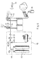
- the device for projecting lightweight materials comprises a generally cylindrical casing 1 comprising an annular shoulder 2 and in which is fixed an air amplifying tranvector 3 by two studs not shown in FIGS. .
- the casing 1 is articulated between two legs 4 a, 4 b a stirrup 4 in the general shape of U, the base 4c is mounted to rotate about an axis 5 integral with a generally cylindrical socket 6, the axis of rotation 5 of the bracket 4 being coaxial with the axis of symmetry of the base 6.
- the device comprises an ejector member 7 located within a cylindrical outer tube 7 a of which one end is completed by a collar 8 provided with holes 9 adapted to come to the right of corresponding holes made on the side wall of the shoulder 2 of the casing 1 to allow the fixing of the ejection element 7 on the casing 1.
- the ejection element 7 comprises, moreover, a second so-called inner frustoconical tube extending coaxially with the first tube 7 outside said 7b, said second frustoconical inner tube 7b which widens from the free end of the front part 3a of the transvector 3 on which bears said second inner truncated tube 7b until free end of the first outer tube 7 a .
- the device comprises a thermoformed cover 11 secured to the casing 1 by clipping and coming to cover the rear part 3b of the transvector 3 as described in US Pat 4,046,492 for example.
- the base 6 consists of a cylindrical hollow body comprises three legs 12 uniformly distributed around the base 6 and secured to its side wall.
- the base 6 furthermore comprises a compressed air distribution element 13 positioned inside said base 6 and comprising an inlet 14 connected to the outlet of a compressed air supply unit 15 which the three further outlets 16, 17 and 18 will be detailed later.
- Outlets 16, 17 and 18 of the compressed air distribution element 13 consist of a first outlet 16 connected to the compressed air inlet of the transvector amplifier 3, a second output 17 said automatic shutter, that is to say an outlet which is closed for example by a ball valve when no connection means is connected to said output and which is open when a connection means is connected thereto, adapted to be connected to the input of a distribution element of a second light material projection device, and a third outlet 18 connected by connecting means to a material reservoir light and / or distribution means of the aqueous phase positioned in the air flow projected by the air amplifier transvector 3 as will be detailed below.
- the compressed air distribution element 13 is secured inside the base 6 in such a way that that the inlet 14 adapted to be connected to a compressed air supply unit 15 and the second outlet 17 adapted to be connected to the input of a distribution element of a second device for projecting light materials protrudes of the side wall of the base 6.
- first outlet 16 of the compressed air distribution element 13 extending inside the base 6 is connected by first connection means 19 which project from the upper face of the base 6 through a hole 20 carried out on said upper face of the base 6 which passes through the branches 4a, 4b of the yoke 4 and through a hole 21 formed in the cover 11 integral thermoformed of the casing 1, to the compressed air inlet 22 of the air amplifier transvector 3.
- the first connection means 19 connecting the first outlet 16 of the compressed air distribution element 13 to the air inlet compressed 22 of the transvector 3 comprises a solenoid valve 23 advantageously consisting in a so-called proportional solenoid valve capable of varying the flow of compressed air transmitted to the amplifier transvector 3, the flow rate of the latter being proportional to the flow rate of compressed air supplying said tr 3 years, positioned inside the base 6 and controlled by control means 24.
- control means 24 are preferably connected to a receiver 25 adapted to receive the information of a control unit 26 having at least one potentiometer 27 and a transmitter 28.
- an operator by operating the potentiometer 27 of the control box 26 can drive the solenoid valve 23 to vary the flow of compressed air supplying the amplifier transvector 3 thus varying the flow rate of the flow of air projected by said transvector 3.
- the second outlet 17 of the compressed air delivery member 13 protrudes from the side wall of the base 6 adjacent the inlet 14 of said compressed air distribution member 13 is capable of being connected by second connection means 29 to the input 14 'of a distribution element 13' of a second light material projection device according to the invention. It will be observed that several devices can thus be connected in series and powered by a compressed air supply unit 15.
- the third outlet 18 of the compressed air distribution element 13 extending inside the base 6 is connected by third connection means 30 which project from the base 6 by a second hole 31 formed on the upper face of said base 6 to distribution means 32 (FIGS. 1 and 2) of the aqueous phase positioned in the flow of air projected by the air-amplifier transvector 3.
- distribution means 32 FIGS. 1 and 2
- a second air amplifier transvector 33 secured to the ejection element 7 and opening radially inside said tubular ejection element 7 in the vicinity of its free end, said second transvector 33 comprising a capillary tube 34 connected by a pipe 35 to a reservoir 36 containing the aqueous phase and extending inside the cylindrical body of the second transvector 33.
- the capillary tube 34 extends inside the generally cylindrical body of the second transvector 33 at an angle ⁇ of approximately 45 ° with respect to the longitudinal axis A of the cylindrical body of the transvector 33 such that the free end of said capillary tube 34 is located on the longitudinal axis of the cylindrical body of the transvector 33 in the front portion 33 a which creates a high pressure, the rear part 33 b of the transvector 33 being the seat a depression, when the cylindrical body of the transvector is supplied with compressed air.
- the air flow created in the front portion of the cylindrical body of the tranvector 33 creates a vacuum at the inlet of the capillary tube 34 which sucks the aqueous phase contained in the tank 36 connected to the tube capillary 34 through the pipe 35.
- the reservoir 36 may comprise means for creating an overpressure inside said reservoir 36 in order to facilitate and regulate the flow rate of the aqueous phase flowing from the capillary tube 34.
- the dispensing means 32 of the aqueous phase comprises a sleeve 37 received in a flexible or semi-rigid permeable whose free ends are respectively integral with the front portion 33 a of the second transvector 33, that is to say integral with the cylindrical hollow body opening radially in the ejection element 7, and the inner wall of the tubular ejection element 7 diametrically opposite the wall where the transvector 33 opens such that the sleeve 37 extends diametrically inside the tubular ejection element 7 near its free end.
- the aqueous phase contained in the reservoir 36 is projected into the sleeve 37 which extends diametrically inside the element.
- ejection 7 in which is channeled a flow of air generated by the first transvector 3 thus forming at the outlet of the ejection element 7 an emulsion which can consist either in foam or in theater snow, either in bubbles depending on the nature of the aqueous phase contained in the reservoir 36.
- the third connection means 30 comprise a second solenoid valve 38 positioned inside the base 6 between the third outlet 18 of the compressed air distribution element 13 and the distribution means 32 of the aqueous phase, said second solenoid valve 38 being controlled by the control means 24.
- the third connection means 30 connected to the third outlet of the compressed air distribution element 13 are no longer connected to the distribution means of the aqueous phase but to the side wall of a reservoir 40 light materials such as confetti or similar, comprising on its upper wall an outlet 41 connected by flexible connection means to a flexible pipe bend 42 integral with the rear part 3b of the transvector 3, that is, say the part of the transvector 3 where creates a strong depression when said transvector 3 is supplied with compressed air.
- the transvector 3 when the transvector 3 is supplied with compressed air, a high vacuum is created in the flexible elbow tube 42 sucking the confetti contained in the reservoir 40 to project them by the ejection element 7 which has been advantageously replaced by a ejection element 7 not including sleeve 37 extending diametrically near its free end to prevent clogging during the ejection of confetti.
- said ejector 7 consists of a frusto-conical tube 7 has said outer member comprising close to its small base secured at the front end of the transvector 3 a second frustoconical tube said inner 7b coaxial with the first frusto-conical outer tube 7a, extending inside the latter over a length at least less than half the outer tube of length 7a, and preferably over a third length of the length of the outer tube 7a, and fastened to the outer tube by spacers 43, said outer tube 7 is comprising on its periphery over a length corresponding to the length of the frustoconical tube interior 7b from its small base 44 regularly spaced holes.
- the free end of the ejection element 7, close to the small base of the latter comprises a flange 8 provided with holes 9 adapted to accommodate bolts for fixing said ejection element 7 on the casing 1 of the device.
- the compressed air supply unit consists of one or more bottles 45, advantageously mounted on a carriage not shown in the figures, connected to a ramp 46 which is connected to a pressure regulator 47 by a coupling 48 T whose branches are respectively provided with a valve 49 a, 49 b, 49 c respectively connected to the ramp 46, a compressor 50 and expander 47, an air filter 51 is advantageously positioned at the outlet of the expander 47 to prevent impurities from damaging the transvectors 3 or 33.
Landscapes
- Engineering & Computer Science (AREA)
- General Engineering & Computer Science (AREA)
- Jet Pumps And Other Pumps (AREA)
- Non-Portable Lighting Devices Or Systems Thereof (AREA)
- Toys (AREA)
- Manufacturing Of Micro-Capsules (AREA)
- Projection Apparatus (AREA)
- Overhead Projectors And Projection Screens (AREA)
Claims (12)
- Vorrichtung zur Auswerfung leichter Stoffe, wie Konfetti oder dergleichen und/oder Emulsionen, Typ Luft in flüssiger Phase, wie Schaum, Theaterschnee, Blasen oder dergleichen, die einen Behälter (36, 40) umfasst, in dem sich die leichten Stoffe oder eine wässrige Phase befindet und der durch Verbindungsmittel an eine Vorrichtung zum Evakuieren, wie einem Luftverstärker-Transvektor (3) angeschlossen ist, dem Druckluft durch Druckluftflaschen (45) zugeführt wird, die mit einem Druckminderventil (47) ausgestattet sind, wobei der Behälter (36, 40), der die leichten Stoffe enthält, mit dem hinteren Ende (3b) des Transvektors (3) verbunden ist, wo ein Druckabfall stattfindet, wobei ein starker Überdruck am gegenüberliegenden vorderen Ende (3a) des besagten Transvektors (3) stattfindet, an das ein röhrenförmiges Auswurfelement (7) angeschlossen ist, das vorzugsweise kegelstumpfförmig ist, und das sich von dem Transvektor (3) nach Außen ausweitet, um den Luftstrom, der von dem besagten Transvektor (3) erzeugt wird, zu lenken, um die leichten Stoffe in die Luft auszuwerfen, dadurch gekennzeichnet, dass sie ein Element zur Verteilung der Druckluft (13) umfasst, das mindestens einen Eingang (14), der mit dem Ausgang des Druckminderventils (47) verbunden ist, und mindestens zwei Ausgänge (16, 17) hat, wobei ein erster Ausgang (16) mit dem Drucklufteingang (22) des Luftverstärker-Transvektors (3) verbunden ist und ein sogenannter zweiter Ausgang (17), mit automatischer Abdichtung, dass heißt ein Ausgang, der abgedichtet ist, zum Beispiel durch eine kleine Kugel, die eine Klappe bildet, wenn kein Verbindungsmittel an den besagten Ausgang angeschlossen ist und die geöffnet ist, wenn dort ein Verbindungsmittel angeschlossen ist, an den Eingang (14') eines Elementes zur Verteilung (13') einer zweiten Vorrichtung zur Auswerfung leichter Stoffe angeschlossen werden kann.
- Vorrichtung zur Auswerfung leichter Stoffe nach dem vorstehenden Anspruch, dadurch gekennzeichnet, dass das Element zur Verteilung der Druckluft (13) einen dritten Ausgang (18) umfasst, der durch Verbindungsmittel (30) an den Behälter (40) für leichte Stoffe und/oder an Mittel zur Verteilung (32) der wässrigen Phase angeschlossen ist, die in dem Luftstrom angeordnet sind, der von dem Luftverstärker-Transvektor (3) ausgeworfen wird.
- Vorrichtung zur Auswerfung leichter Stoffe nach Anspruch 2, dadurch gekennzeichnet, dass die Mittel zur Verteilung (32) der wässrigen Phase aus einem zweiten Luftverstärker-Transvektor (33) bestehen, der fest mit dem röhrenförmigen Auswurfelement (7) verbunden ist,
wobei er radial in das besagte Auswurfelement (7) einmündet, in der Nähe seines freien Endes, wobei der besagte zweite Transvektor (33) ein Kapillarrohr (34) umfasst, das durch ein Rohr (35) mit einem zweiten Behälter (36) der wässrigen Phase verbunden ist und sich in dem zylindrischen Teil des zweiten Transvektor (33) ausbreitet und dabei einen Winkel α von etwa 45°, bezogen auf die Längsachse A des zylindrischen Teils des besagten zweiten Transvektors (33) bildet und zwar so, dass sich das freie Ende des besagten Kapillarrohrs(34) auf der Längsachse des zylindrischen Teils des zweiten Transvektors (33) befindet. - Vorrichtung zur Auswerfung leichter Stoffe nach Anspruch 3, dadurch gekennzeichnet, dass die Mittel zur Verteilung (32) der wässrigen Phase einen Stutzen (37) aus geschmeidigen oder halbsteifen durchlässigen Material umfassen, dessen freie Enden jeweils mit dem vorderen Teil (3a) des Transvektors (3) fest verbunden sind, dass heißt fest verbunden mit dem hohlen zylindrischen Teil und radial in das röhrenförmige Auswurfelement (7) einmünden und mit der Innenwand des röhrenförmigen Auswurfelementes (7), genau gegenüber der Wand, wo der zweite Transvektor (33) einmündet und zwar so, dass der Stutzen (37) diametral in dem röhrenförmigen Auswurfelement (7) in der Nähe seines freien Endes verläuft.
- Vorrichtung zur Auswerfung leichter Stoffe nach einem der vorstehenden Ansprüche 1 bis 3, dadurch gekennzeichnet, dass sie ein Magnetventil (23) umfasst, das zwischen dem ersten Ausgang (16) des Elementes zur Verteilung der Druckluft (13) und dem Drucklufteingang (22) des ersten Luftverstärker-Transvektors (3) angeordnet ist und von Bedienungsmittel (24) gesteuert wird.
- Vorrichtung zur Auswerfung leichter Stoffe nach Anspruch 5, dadurch gekennzeichnet, dass das Magnetventil (23) aus einem proportionalen Magnetventil besteht, das eine Änderung des Druckluftdurchsatzes bewirken kann, der an den ersten Luftverstärker-Transvektor (3) weitergeleitet wird, wobei der Durchsatz proportional zum Luftdurchsatz ist, der von dem besagten Transvektor (3) ausgeschleudert wird.
- Vorrichtung zur Auswerfung leichter Stoffe nach einem der vorstehenden Ansprüche 2 bis 6, dadurch gekennzeichnet, dass sie ein zweites Magnetventil (38) umfasst, das zwischen dem dritten Ausgang (18) des Elementes zur Verteilung der Druckluft (13) und dem Behälter (40) für die leichten Stoffe und/oder den Mitteln zur Verteilung (32) der wässrigen Phase angeordnet ist, wobei das besagte zweite Magnetventil (38) von den Bedienungselementen (24) gesteuert wird.
- Vorrichtung zur Auswerfung leichter Stoffe nach einem der vorstehenden Ansprüche 5 bis 7, dadurch gekennzeichnet, dass die Bedienungselemente (24) an einen Empfänger (25) angeschlossen sind, der die Informationen eines Steuerkastens (26) empfangen kann, der zumindest ein Potentiometer (27) und einen Sender (28) umfasst.
- Vorrichtung zur Auswerfung leichter Stoffe nach einem der vorstehenden Ansprüche, dadurch gekennzeichnet, dass das röhrenförmige Auswurfelement (7) aus einem sogenannten externen kegelstumpfförmigen Rohr (7a) besteht, das in der Nähe seiner kleinen Basis, die fest mit dem vorderen Ende des ersten Transvektors (3) verbunden ist, ein zweites kegelstumpfförmiges Rohr (7b) umfasst, das konzentrisch zum ersten externen Rohr (7a) liegt und in diesem Rohr auf einer Länge verläuft, die mindestens kleiner als die Hälfte der Länge des externen Rohrs (7a) ist und mit dem besagten externen Rohr (7a) durch Verstrebungen (43) fest verbunden ist, wobei das besagte externe Rohr (7a) auf seinem Umfang, auf einer Länge, die der Länge des internen kegelstumpfförmigen Rohrs (7b) ab der kleinen Basis entspricht, Löcher (44) umfasst, die in regelmäßigen Abständen zueinander angeordnet sind.
- Vorrichtung zur Auswerfung leichter Stoffe nach Anspruch 9, dadurch gekennzeichnet, dass die Wände des internen kegelstumpfförmigen Rohrs (7b) parallel zu den Wänden des externen kegelstumpfförmigen Rohres (7a) verlaufen.
- Vorrichtung zur Auswerfung leichter Stoffe nach einem der vorstehenden Ansprüche, dadurch gekennzeichnet, dass der erste Luftverstärker-Transvektor (3) in einem Gehäuse (1) angeordnet ist, das insgesamt zylindrisch ist und einen ringförmigen Absatz (2) umfasst und zwischen zwei Schenkeln (4a, 4b) eines Bügels (4) gelenkig angebracht ist, dessen allgemeine Form ein U ist und dessen Basis (4c) frei drehbar um eine Achse herum montiert ist, die fest mit einer Grundplatte (6) verbunden ist, die insgesamt zylindrisch ist, wobei die Drehachse (5) des Bügels (4) bezogen auf die Grundplatte (6) vorzugsweise konzentrisch zu der Symmetrieachse der Grundplatte (6) ist.
- Vorrichtung zur Auswerfung leichter Stoffe nach Anspruch 11, dadurch gekennzeichnet, dass das Element zur Verteilung der Druckluft (13) in der Grundplatte (6) angeordnet ist und zwar so, dass der Eingang (14) des besagten Verteilungselementes (13) und der zweite Ausgang mit Abdichtung (17) über die Seitenwand der Grundplatte (6) übersteht.
Applications Claiming Priority (3)
| Application Number | Priority Date | Filing Date | Title |
|---|---|---|---|
| FR0303273A FR2851996B1 (fr) | 2003-03-05 | 2003-03-05 | Dispositif de projection de materiaux legers tels que des confettis ou analogues et/ou des emulsions telles que de la mousse, de la neige ou analogue |
| FR0303273 | 2003-03-05 | ||
| PCT/FR2004/000474 WO2004081484A1 (fr) | 2003-03-05 | 2004-03-01 | Dispositif de projection de materiaux legers tels que des confettis ou analogues et/ou des emulsions telles que de la mousse, de la neige ou analogue |
Publications (2)
| Publication Number | Publication Date |
|---|---|
| EP1604166A1 EP1604166A1 (de) | 2005-12-14 |
| EP1604166B1 true EP1604166B1 (de) | 2006-09-06 |
Family
ID=32865376
Family Applications (1)
| Application Number | Title | Priority Date | Filing Date |
|---|---|---|---|
| EP04715926A Expired - Lifetime EP1604166B1 (de) | 2003-03-05 | 2004-03-01 | Vorrichtung zur auswerfung leichter stoffe wie konfetti oder dergleichen und/oder emulsionen wie schaum, schnee oder dergleichen |
Country Status (5)
| Country | Link |
|---|---|
| EP (1) | EP1604166B1 (de) |
| AT (1) | ATE338933T1 (de) |
| DE (1) | DE602004002286T2 (de) |
| FR (1) | FR2851996B1 (de) |
| WO (1) | WO2004081484A1 (de) |
Families Citing this family (4)
| Publication number | Priority date | Publication date | Assignee | Title |
|---|---|---|---|---|
| EP1905495A1 (de) | 2006-09-28 | 2008-04-02 | Hui Xu | Nebelmaschine mit beweglichen Austritt |
| GB2503244A (en) * | 2012-06-20 | 2013-12-25 | Osman Gulum | Confetti launcher |
| CN108261788A (zh) * | 2017-12-08 | 2018-07-10 | 方特欢乐世界(芜湖)经营管理有限公司 | 一种剧场表演用旋转式花瓣抛洒装置 |
| IT201800009243A1 (it) | 2018-10-08 | 2020-04-08 | Super Show Ind Srl | Dispositivo per sparare coriandoli, stelle filanti e simili |
Family Cites Families (4)
| Publication number | Priority date | Publication date | Assignee | Title |
|---|---|---|---|---|
| US4046492A (en) | 1976-01-21 | 1977-09-06 | Vortec Corporation | Air flow amplifier |
| US5015211A (en) * | 1986-12-12 | 1991-05-14 | Reveen Tyrone J | Confetti cannon |
| US6149495A (en) * | 1999-03-15 | 2000-11-21 | Austin; Joseph James | Confetti and theatrical snow delivery device |
| US6364737B1 (en) | 2000-04-14 | 2002-04-02 | Artistry In Motion, Inc. | Lightweight material projection system |
-
2003
- 2003-03-05 FR FR0303273A patent/FR2851996B1/fr not_active Expired - Fee Related
-
2004
- 2004-03-01 DE DE602004002286T patent/DE602004002286T2/de not_active Expired - Fee Related
- 2004-03-01 WO PCT/FR2004/000474 patent/WO2004081484A1/fr not_active Ceased
- 2004-03-01 EP EP04715926A patent/EP1604166B1/de not_active Expired - Lifetime
- 2004-03-01 AT AT04715926T patent/ATE338933T1/de not_active IP Right Cessation
Also Published As
| Publication number | Publication date |
|---|---|
| DE602004002286T2 (de) | 2007-04-05 |
| WO2004081484A1 (fr) | 2004-09-23 |
| FR2851996B1 (fr) | 2005-06-03 |
| ATE338933T1 (de) | 2006-09-15 |
| DE602004002286D1 (de) | 2006-10-19 |
| EP1604166A1 (de) | 2005-12-14 |
| FR2851996A1 (fr) | 2004-09-10 |
Similar Documents
| Publication | Publication Date | Title |
|---|---|---|
| EP0642839B1 (de) | Verfahren und Vorrichtung zum Spenden und Lagern eines, in einem mit Treibgas unter Druck gesetzten Behälter enthaltenen, flüssigen Produktes | |
| CA2518239C (fr) | Procede et dispositif de nebulisation | |
| FR2550996A1 (fr) | Recipient d'encre et dispositif recuperateur d'encre, notamment pour imprimante | |
| EP2389203A1 (de) | Gerät zur dekontamination durch atomisierung | |
| FR2512224A1 (fr) | Dispositif de production de jets de fluide puises sous pression | |
| FR2537892A1 (fr) | Pulverisateur aspirant | |
| WO1998024556A1 (fr) | Dispositif de distribution de produit fluide du type bicomposant | |
| EP0487412A1 (de) | Dosierventil für in einem drucklosen Behälter enthaltenen Flüssigkeiten | |
| EP2478972A1 (de) | Reinigungsvorrichtung für Spritzpistole | |
| FR2543024A1 (fr) | Dispositif distributeur sous la forme d'un pistolet de calfatage | |
| FR2767562A1 (fr) | Dispositif d'alimentation en carburant a partir d'un reservoir a pot accumulateur | |
| FR2526711A1 (fr) | Imprimante a jets d'encre et dispositif de retablissement de fonction par succion | |
| FR2763507A1 (fr) | Inhalateur | |
| EP1914003A1 (de) | Vorrichtung zur Herstellung von Schaum | |
| EP1604166A1 (de) | Vorrichtung zur auswerfung leichter stoffe wie konfetti oder dergleichen und/oder emulsionen wie schaum, schnee oder dergleichen | |
| FR2791033A1 (fr) | Systeme de remplissage de recipients | |
| EP1867396B1 (de) | Lackierspritzpistole mit Druckdose | |
| EP0927826A1 (de) | Pumpsystem für Flüssigkeiten | |
| FR2726476A1 (fr) | Embout de pulverisation d'un liquide a l'interieur du conduit auditif externe et dispositif de pulverisation correspondant | |
| FR2645062A1 (fr) | Pistolet pneumatique de sablage pour le decapage local de surfaces a metalliser | |
| EP4544908B1 (de) | Verschlussvorrichtung und vorrichtung zum entfernen von pflanzenschutzmitteln | |
| FR3099063A1 (fr) | Extincteur pyrotechnique pour véhicule | |
| EP1647419B1 (de) | Austragsdüse für körniges Material | |
| EP0655282A1 (de) | Apparat zur Zerstäubung flüssiger Riechstoffe | |
| FR3167315A1 (fr) | Dispositif de pulvérisation ou de projection de matériau pulvérulent, fragmentaire ou liquide |
Legal Events
| Date | Code | Title | Description |
|---|---|---|---|
| PUAI | Public reference made under article 153(3) epc to a published international application that has entered the european phase |
Free format text: ORIGINAL CODE: 0009012 |
|
| 17P | Request for examination filed |
Effective date: 20051004 |
|
| AK | Designated contracting states |
Kind code of ref document: A1 Designated state(s): AT BE BG CH CY CZ DE DK EE ES FI FR GB GR HU IE IT LI LU MC NL PL PT RO SE SI SK TR |
|
| AX | Request for extension of the european patent |
Extension state: AL LT LV MK |
|
| GRAP | Despatch of communication of intention to grant a patent |
Free format text: ORIGINAL CODE: EPIDOSNIGR1 |
|
| DAX | Request for extension of the european patent (deleted) | ||
| GRAS | Grant fee paid |
Free format text: ORIGINAL CODE: EPIDOSNIGR3 |
|
| GRAA | (expected) grant |
Free format text: ORIGINAL CODE: 0009210 |
|
| AK | Designated contracting states |
Kind code of ref document: B1 Designated state(s): AT BE BG CH CY CZ DE DK EE ES FI FR GB GR HU IE IT LI LU MC NL PL PT RO SE SI SK TR |
|
| PG25 | Lapsed in a contracting state [announced via postgrant information from national office to epo] |
Ref country code: IT Free format text: LAPSE BECAUSE OF FAILURE TO SUBMIT A TRANSLATION OF THE DESCRIPTION OR TO PAY THE FEE WITHIN THE PRESCRIBED TIME-LIMIT;WARNING: LAPSES OF ITALIAN PATENTS WITH EFFECTIVE DATE BEFORE 2007 MAY HAVE OCCURRED AT ANY TIME BEFORE 2007. THE CORRECT EFFECTIVE DATE MAY BE DIFFERENT FROM THE ONE RECORDED. Effective date: 20060906 Ref country code: CZ Free format text: LAPSE BECAUSE OF FAILURE TO SUBMIT A TRANSLATION OF THE DESCRIPTION OR TO PAY THE FEE WITHIN THE PRESCRIBED TIME-LIMIT Effective date: 20060906 Ref country code: SK Free format text: LAPSE BECAUSE OF FAILURE TO SUBMIT A TRANSLATION OF THE DESCRIPTION OR TO PAY THE FEE WITHIN THE PRESCRIBED TIME-LIMIT Effective date: 20060906 Ref country code: AT Free format text: LAPSE BECAUSE OF FAILURE TO SUBMIT A TRANSLATION OF THE DESCRIPTION OR TO PAY THE FEE WITHIN THE PRESCRIBED TIME-LIMIT Effective date: 20060906 Ref country code: RO Free format text: LAPSE BECAUSE OF FAILURE TO SUBMIT A TRANSLATION OF THE DESCRIPTION OR TO PAY THE FEE WITHIN THE PRESCRIBED TIME-LIMIT Effective date: 20060906 Ref country code: FI Free format text: LAPSE BECAUSE OF FAILURE TO SUBMIT A TRANSLATION OF THE DESCRIPTION OR TO PAY THE FEE WITHIN THE PRESCRIBED TIME-LIMIT Effective date: 20060906 Ref country code: SI Free format text: LAPSE BECAUSE OF FAILURE TO SUBMIT A TRANSLATION OF THE DESCRIPTION OR TO PAY THE FEE WITHIN THE PRESCRIBED TIME-LIMIT Effective date: 20060906 Ref country code: IE Free format text: LAPSE BECAUSE OF FAILURE TO SUBMIT A TRANSLATION OF THE DESCRIPTION OR TO PAY THE FEE WITHIN THE PRESCRIBED TIME-LIMIT Effective date: 20060906 Ref country code: NL Free format text: LAPSE BECAUSE OF FAILURE TO SUBMIT A TRANSLATION OF THE DESCRIPTION OR TO PAY THE FEE WITHIN THE PRESCRIBED TIME-LIMIT Effective date: 20060906 Ref country code: PL Free format text: LAPSE BECAUSE OF FAILURE TO SUBMIT A TRANSLATION OF THE DESCRIPTION OR TO PAY THE FEE WITHIN THE PRESCRIBED TIME-LIMIT Effective date: 20060906 |
|
| REG | Reference to a national code |
Ref country code: GB Ref legal event code: FG4D Free format text: NOT ENGLISH |
|
| REG | Reference to a national code |
Ref country code: CH Ref legal event code: EP |
|
| REG | Reference to a national code |
Ref country code: IE Ref legal event code: FG4D Free format text: LANGUAGE OF EP DOCUMENT: FRENCH |
|
| REF | Corresponds to: |
Ref document number: 602004002286 Country of ref document: DE Date of ref document: 20061019 Kind code of ref document: P |
|
| PG25 | Lapsed in a contracting state [announced via postgrant information from national office to epo] |
Ref country code: BG Free format text: LAPSE BECAUSE OF FAILURE TO SUBMIT A TRANSLATION OF THE DESCRIPTION OR TO PAY THE FEE WITHIN THE PRESCRIBED TIME-LIMIT Effective date: 20061206 Ref country code: SE Free format text: LAPSE BECAUSE OF FAILURE TO SUBMIT A TRANSLATION OF THE DESCRIPTION OR TO PAY THE FEE WITHIN THE PRESCRIBED TIME-LIMIT Effective date: 20061206 Ref country code: DK Free format text: LAPSE BECAUSE OF FAILURE TO SUBMIT A TRANSLATION OF THE DESCRIPTION OR TO PAY THE FEE WITHIN THE PRESCRIBED TIME-LIMIT Effective date: 20061206 |
|
| PG25 | Lapsed in a contracting state [announced via postgrant information from national office to epo] |
Ref country code: ES Free format text: LAPSE BECAUSE OF FAILURE TO SUBMIT A TRANSLATION OF THE DESCRIPTION OR TO PAY THE FEE WITHIN THE PRESCRIBED TIME-LIMIT Effective date: 20061217 |
|
| GBT | Gb: translation of ep patent filed (gb section 77(6)(a)/1977) |
Effective date: 20061213 |
|
| PG25 | Lapsed in a contracting state [announced via postgrant information from national office to epo] |
Ref country code: PT Free format text: LAPSE BECAUSE OF FAILURE TO SUBMIT A TRANSLATION OF THE DESCRIPTION OR TO PAY THE FEE WITHIN THE PRESCRIBED TIME-LIMIT Effective date: 20070219 |
|
| NLV1 | Nl: lapsed or annulled due to failure to fulfill the requirements of art. 29p and 29m of the patents act | ||
| REG | Reference to a national code |
Ref country code: IE Ref legal event code: FD4D |
|
| PLBE | No opposition filed within time limit |
Free format text: ORIGINAL CODE: 0009261 |
|
| STAA | Information on the status of an ep patent application or granted ep patent |
Free format text: STATUS: NO OPPOSITION FILED WITHIN TIME LIMIT |
|
| 26N | No opposition filed |
Effective date: 20070607 |
|
| PG25 | Lapsed in a contracting state [announced via postgrant information from national office to epo] |
Ref country code: MC Free format text: LAPSE BECAUSE OF NON-PAYMENT OF DUE FEES Effective date: 20070331 |
|
| PG25 | Lapsed in a contracting state [announced via postgrant information from national office to epo] |
Ref country code: GR Free format text: LAPSE BECAUSE OF FAILURE TO SUBMIT A TRANSLATION OF THE DESCRIPTION OR TO PAY THE FEE WITHIN THE PRESCRIBED TIME-LIMIT Effective date: 20061207 |
|
| PG25 | Lapsed in a contracting state [announced via postgrant information from national office to epo] |
Ref country code: EE Free format text: LAPSE BECAUSE OF FAILURE TO SUBMIT A TRANSLATION OF THE DESCRIPTION OR TO PAY THE FEE WITHIN THE PRESCRIBED TIME-LIMIT Effective date: 20060906 |
|
| REG | Reference to a national code |
Ref country code: CH Ref legal event code: PL |
|
| PG25 | Lapsed in a contracting state [announced via postgrant information from national office to epo] |
Ref country code: LI Free format text: LAPSE BECAUSE OF NON-PAYMENT OF DUE FEES Effective date: 20080331 Ref country code: CH Free format text: LAPSE BECAUSE OF NON-PAYMENT OF DUE FEES Effective date: 20080331 |
|
| REG | Reference to a national code |
Ref country code: FR Ref legal event code: CJ |
|
| PG25 | Lapsed in a contracting state [announced via postgrant information from national office to epo] |
Ref country code: LU Free format text: LAPSE BECAUSE OF NON-PAYMENT OF DUE FEES Effective date: 20070301 Ref country code: CY Free format text: LAPSE BECAUSE OF FAILURE TO SUBMIT A TRANSLATION OF THE DESCRIPTION OR TO PAY THE FEE WITHIN THE PRESCRIBED TIME-LIMIT Effective date: 20060906 |
|
| PGFP | Annual fee paid to national office [announced via postgrant information from national office to epo] |
Ref country code: DE Payment date: 20090410 Year of fee payment: 6 Ref country code: FR Payment date: 20090331 Year of fee payment: 6 |
|
| PG25 | Lapsed in a contracting state [announced via postgrant information from national office to epo] |
Ref country code: TR Free format text: LAPSE BECAUSE OF FAILURE TO SUBMIT A TRANSLATION OF THE DESCRIPTION OR TO PAY THE FEE WITHIN THE PRESCRIBED TIME-LIMIT Effective date: 20060906 Ref country code: HU Free format text: LAPSE BECAUSE OF FAILURE TO SUBMIT A TRANSLATION OF THE DESCRIPTION OR TO PAY THE FEE WITHIN THE PRESCRIBED TIME-LIMIT Effective date: 20070307 |
|
| PGFP | Annual fee paid to national office [announced via postgrant information from national office to epo] |
Ref country code: BE Payment date: 20090528 Year of fee payment: 6 |
|
| PGFP | Annual fee paid to national office [announced via postgrant information from national office to epo] |
Ref country code: GB Payment date: 20090421 Year of fee payment: 6 |
|
| BERE | Be: lapsed |
Owner name: UNIVERSAL EFFECTS Effective date: 20100331 |
|
| GBPC | Gb: european patent ceased through non-payment of renewal fee |
Effective date: 20100301 |
|
| REG | Reference to a national code |
Ref country code: FR Ref legal event code: ST Effective date: 20101130 |
|
| PG25 | Lapsed in a contracting state [announced via postgrant information from national office to epo] |
Ref country code: FR Free format text: LAPSE BECAUSE OF NON-PAYMENT OF DUE FEES Effective date: 20100331 |
|
| PG25 | Lapsed in a contracting state [announced via postgrant information from national office to epo] |
Ref country code: DE Free format text: LAPSE BECAUSE OF NON-PAYMENT OF DUE FEES Effective date: 20101001 Ref country code: BE Free format text: LAPSE BECAUSE OF NON-PAYMENT OF DUE FEES Effective date: 20100331 |
|
| PG25 | Lapsed in a contracting state [announced via postgrant information from national office to epo] |
Ref country code: GB Free format text: LAPSE BECAUSE OF NON-PAYMENT OF DUE FEES Effective date: 20100301 |