EP1603211A1 - Detection and disconnection device for broken covered conductor in medium voltage electrical network - Google Patents
Detection and disconnection device for broken covered conductor in medium voltage electrical network Download PDFInfo
- Publication number
- EP1603211A1 EP1603211A1 EP05011450A EP05011450A EP1603211A1 EP 1603211 A1 EP1603211 A1 EP 1603211A1 EP 05011450 A EP05011450 A EP 05011450A EP 05011450 A EP05011450 A EP 05011450A EP 1603211 A1 EP1603211 A1 EP 1603211A1
- Authority
- EP
- European Patent Office
- Prior art keywords
- voltage
- disconnection
- unit
- covered
- broken
- Prior art date
- Legal status (The legal status is an assumption and is not a legal conclusion. Google has not performed a legal analysis and makes no representation as to the accuracy of the status listed.)
- Withdrawn
Links
Images


Classifications
-
- H—ELECTRICITY
- H02—GENERATION; CONVERSION OR DISTRIBUTION OF ELECTRIC POWER
- H02H—EMERGENCY PROTECTIVE CIRCUIT ARRANGEMENTS
- H02H5/00—Emergency protective circuit arrangements for automatic disconnection directly responsive to an undesired change from normal non-electric working conditions with or without subsequent reconnection
- H02H5/10—Emergency protective circuit arrangements for automatic disconnection directly responsive to an undesired change from normal non-electric working conditions with or without subsequent reconnection responsive to mechanical injury, e.g. rupture of line, breakage of earth connection
-
- H—ELECTRICITY
- H02—GENERATION; CONVERSION OR DISTRIBUTION OF ELECTRIC POWER
- H02H—EMERGENCY PROTECTIVE CIRCUIT ARRANGEMENTS
- H02H1/00—Details of emergency protective circuit arrangements
- H02H1/0061—Details of emergency protective circuit arrangements concerning transmission of signals
Definitions
- the subject of this invention is a detection and disconnection device for a broken covered conductor in a medium voltage electrical network.
- this is a protection device, which disconnects a broken covered conductor lying on the ground from electrical power. Therefore such electrical line is safe for people and other living beings around this area.
- this invention belongs to class H01H 83/14 and additionally to class H01H 83/12.
- the technical problem being solved by the invention is such a device construction that will enable a fast, efficient and safe disconnection of a broken electrical line from electrical power source, fast and user-friendly detection and localization of the broken part of the line, and together with other equipment in the electrical network the total reconstruction of electrical power supply; the device could be used on existing and new electrical lines.
- the problem is solved with a detection and disconnection device for a broken covered conductor in a medium voltage electrical network.
- the device is constructed of an indication unit and a disconnection unit.
- the disconnection unit is positioned in front of the indication unit looking in the direction of power supply.
- the information signal between the two units can be transmitted through wired or wireless carriers.
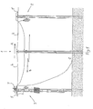
- Fig. 1 we have the detection and disconnection device for a broken covered conductor in a medium voltage electrical network 1, consisting of the indication unit (2) and the disconnection unit (3), which are as a rule separately mounted on the appertain poles (6).
- a disconnection device (3) is usually mounted on a pole (6) at the beginning of covered conductors (4), whereas the indication unit (2) is mounted at the end of covered conductors (4), as shown in Fig. 1.
- In front of the disconnection unit (3) and behind the indication unit (2) we have bar conductors (5) or some other suitable conductors.
- the electrical line (1) is charged in the direction A, meaning that the units (2) and (3) are placed on both ends of covered conductors (4), in front of and behind bare conductors (5) and in the above-mentioned order. As a rule, there are three bare conductors (5) and the same number of covered conductors (4) in direction A. If the covered conductor (4) is broken between the indication unit (2) and the disconnection unit (3), the indication unit (2) senses the voltage drop in one of the phases and sends information through wired or wireless carriers to the disconnection unit (3) in direction B. The disconnection unit (3) disconnects the line immediately from power source through a covered conductor (4) and therefore the covered conductor lying on the ground C is no longer a life threat.
- the disconnection unit (3) disconnects the covered conductor (4) line only if the detection unit (2) senses voltage drop or complete outage of voltage in one or more phases. If voltage conditions on both ends of covered conductor (4) are conserved or if they are changed in the same way in the electrical line (1), the disconnection unit (3) does not disconnect the line. In this case unnecessary disconnections of electrical lines (1) have been eliminated.
- the indication unit (2) can be programmed in such a way that it can send the same information to the disconnection unit (3) and to the centre responsible for maintenance of electrical lines. In this case the maintenance centre can easily and very quickly fix or change the broken covered conductor (4).
- the variation of the device according to the invention or the variation of the indication unit (2) and disconnection unit (3) is determined by the power supply and several different feasible examples are possible.
- the indication unit (2) is mounted on pole (6), between both ends of covered conductors (4) and the beginnings of bare conductors (5).
- the number of conductors 4 and 5 is optional.
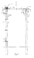
- the indication unit (2) consists of a voltage indicator (9) with a transmitter (13), which are mounted on a pole (6) and of voltage transformer (14),which is mounted on a bracket (21), and with an electrical conductor (19) joined with corresponding covered conductors (4). Every covered conductor (4) must have at least one voltage transformer (14). Covered conductors (4) are connected with corresponding bare conductors (5) through bridging bindings (20).
- the voltage indicator (9) is charged directly from Lithium batteries, which are in the same housing as the voltage indicators 9. Instead of a voltage transformer (14), we can use a capacitive insulator (12).
- the disconnection device (3) On one of the poles (6) the disconnection device (3) is mounted at the end of bare conductors (5) and at the beginning of covered conductors (4).
- the disconnection unit (3) consisting of voltage indicator (9), signal receiver (8), AC/DC charger (10), accumulator batteries (11), voltage transformer (14) mounted on a bracket (21) and through the electrical conductor (19) joined with covered conductors (4) and a motor gear switch (7), that is mounted on the top of the pole (6).
- the charger (10) is connected with the switch (7) by means of a cable 22.
- the signal receiver (8) of the voltage indicator (9) is constructed in a such way that it can receive wireless signals (GSM, radio wave, optical fiber) or wired signals depending on the variation of the transmitter (13) of the indication unit (2).
- the disconnection unit (3) can be charged from many different power sources.
- the device works as follows: In the case when one of the covered conductors (4) is broken and the voltage drops in this part of a medium voltage line (1), the voltage drop is registered by the voltage indicator (9) in the indication unit (2). This information is sent by the transmitter (13) in the direction B to the signal receiver (8) and then to the voltage indicator (9) of the disconnection unit (3).
- the signal receiver (8) can be used as a transmitter, too, and can inform the control centre about the broken voltage line (1).
- the indication unit (2) consists of a voltage indicator (9) with a transmitter (13) and of an AC/DC charger (10) with an accumulator battery (11), both mounted on a pole (6).
- a voltage transformer (14) which is mounted on a pole (6) with a bracket (21), joined with the electrical line (19) and a covered conductor (4).
- transformers (14) can be used; they are joined with bare conductors 5 with bridge bindings (20).
- a capacitive insulator (12) instead of voltage transformer (14).
- the disconnection unit (3) is mounted on a pole (6) at the beginning of covered conductors (4).
- the disconnection unit 3 consists of a voltage indicator (9) with a receiver (8), an AC/DC charger (10) and an accumulator battery (11).
- the above-mentioned elements are connected with a cable (22) and the other end of the cable is connected to a switch (7).
- one or more voltage transformers (14) are also required; they are mounted on a pole (6) with a bracket (21), joined with the electrical line (19) and bare conductors (5). Bare conductors (5) are joined, over a switch (7), with covered conductors (4).
- a capacitive insulator (12) instead of voltage transformer (14).
- the device works as follows:
- the voltage indicator (9) of the indication unit (2) with help of the voltage transformer (14) senses voltage drop in the broken covered conductor (4). This information is sent by transmitter (13) in direction B to the signal receiver (8) with a voltage indicator (9) on the side of the disconnection unit (3).
- the voltage indicator (9) with a transmitter (13) in the indication unit (2) is charged with a charger (10) powered by an accumulator battery (11).
- an AC/DC charger (10) with battery (11) charges the voltage indicator (9) with a receiver (8).
- the indication unit (2) consists of a voltage indicator (9) with transmitter (13), solar panel (16), DC/DC charger (18) with accumulator battery (11), and capacitive insulators (12).
- the solar panel (16) is mounted on a pole (6) with a bracket (17) and capacitive insulators (12) with the other bracket (21). All other stated elements are mounted on a pole (6) directly or indirectly.
- Capacitive insulators (12) are connected with covered conductors (4) through electrical lines (19). Bare conductors (5) are connected with capacitive insulators (12) with bridge bindings (20).
- the DC/DC charger (18) with an accumulator battery (11) is charged with a solar panel (16).
- a voltage transformer (14) instead of capacitive insulator (12.
- the disconnection unit (3) mounted on a pole (6) at the beginning of covered conductors (4) consists of voltage indicator (9) with transmitter (13), solar panel (16), DC/DC charger (18) with accumulator battery (11) and capacitive insulator (12).
- Capacitive insulator (12) is connected to the bare conductor (5) through the electrical line (19).
- Bare conductors (5) are joined with covered conductors (4) through a switch (7).
- DC/DC charger 18 with accumulator battery 11 charges the voltage indicator 9 with transmitter 13, for additional charging the solar panel 16 is used.
- DC/DC charger (18), voltage indicator (9) and switch (7) are connected with a cable (22). Also in this example we can use a voltage transformer (14) instead of capacitive insulator (12.
- the device works as follows: In the indication unit (2), the voltage indicator 9 senses with a help of capacitive insulators (12) a voltage drop in the broken covered conductor (4).
- the transmitter (13) in the indication unit 2 sends information in direction B to the disconnection unit (3) or precisely to the signal receiver (8), which is simultaneously a transmitter 13 of the voltage indicator (9).
- the voltage indicator (9) disconnects the broken covered conductor (4) with help of capacitive insulators (12) with a motor gear switch (7).
- the indication unit (2) consists of an AC/DC charger (10) with an accumulator battery (11) and of a voltage indicator (9) with a transmitter (13). All of them are mounted on a pole (6), together with voltage transformer (14), which is mounted on a pole (6) with a bracket (21).
- the voltage transformer (14) is connected with a covered conductor (4) with the electrical line (19).
- voltage transformer (14) we can use a capacitive insulator (12).
- the disconnection unit (3) comprises AC/DC charger (10) with accumulator battery (11), a voltage indicator (9) with a transmitter (13) all of them mounted on a pole (6), a voltage transformer (14), which is, over the electrical line 19, connected with the bar conductor 5.
- the switch (7) is mounted on the top of the pole (6).
- AC/DC charger (10) and voltage indicator (9) are connected with the switch (7) with a cable (22).
- Bare conductor (5) is joined with a covered conductor (4) over the motor gear switch (7).
- the fifth feasible example according to the invention which is not shown in the figures, has its roots in the solution, that both the indication unit (2) and the disconnection unit (3) are mounted in transformer stations instead on the poles (6).
- one of the transformer stations is at the beginning of a medium voltage line (1) and at the beginning of the covered conductors (4), respectively while the second transformer station is at the end of the electrical line (1) and at the end of covered conductors (4), respectively.
- the motor drive of the motor gear switch (7) in the executive point of the voltage line 1 and in the disconnection unit (3), is not specified.
- the switch (7) can be equipped with disconnection spring, magnetic gear or some other gear, which are not shown in the figures. It is the rule that the signal receiver 8, placed on disconnection unit 3 side, must be telecommunicationally harmonized with the transmitter 13 on the side of indicator unit 2.
- accumulator batteries 11
- solar panel (16) can be charged with a solar panel (16), transformers or some other AC or DC power source.
Landscapes
- Remote Monitoring And Control Of Power-Distribution Networks (AREA)
- Measurement Of Current Or Voltage (AREA)
- Measuring Instrument Details And Bridges, And Automatic Balancing Devices (AREA)
- Testing Of Short-Circuits, Discontinuities, Leakage, Or Incorrect Line Connections (AREA)
- Locating Faults (AREA)
Applications Claiming Priority (2)
| Application Number | Priority Date | Filing Date | Title |
|---|---|---|---|
| SI200400155 | 2004-06-01 | ||
| SI200400155A SI21482A (sl) | 2004-06-01 | 2004-06-01 | Naprava za odkrivanje in izklop prekinjenega polizoliranega vodnika v električnih vodih srednje napetosti |
Publications (1)
| Publication Number | Publication Date |
|---|---|
| EP1603211A1 true EP1603211A1 (en) | 2005-12-07 |
Family
ID=33308864
Family Applications (1)
| Application Number | Title | Priority Date | Filing Date |
|---|---|---|---|
| EP05011450A Withdrawn EP1603211A1 (en) | 2004-06-01 | 2005-05-27 | Detection and disconnection device for broken covered conductor in medium voltage electrical network |
Country Status (4)
| Country | Link |
|---|---|
| EP (1) | EP1603211A1 (sl) |
| HR (1) | HRPK20050475B3 (sl) |
| NO (1) | NO20052583L (sl) |
| SI (1) | SI21482A (sl) |
Cited By (7)
| Publication number | Priority date | Publication date | Assignee | Title |
|---|---|---|---|---|
| EP2019323A2 (en) * | 2007-07-27 | 2009-01-28 | Mag. Beziak, Marjan | Device and method for indicating and signalling changes in a three-phase voltage system of power line, with the purpose to detect interrupted conductions |
| CZ302419B6 (cs) * | 2008-10-22 | 2011-05-04 | Vysoká škola bánská - Technická univerzita Ostrava | Zpusob a zarízení pro detekci poruchy vysokonapetového závesného izolovaného vodice |
| EP2533060A1 (fr) | 2011-06-07 | 2012-12-12 | Schneider Electric Industries SAS | Détection directionnelle de defaut terre résistant et de rupture de conducteur moyenne tension |
| EP2687860A1 (fr) | 2012-07-20 | 2014-01-22 | Schneider Electric Industries SAS | Détection directionnelle de défaut terre sensible moyenne tension par corrélation linéaire |
| WO2014018909A1 (en) | 2012-07-27 | 2014-01-30 | San Diego Gas & Electric Company | System for detecting a falling electric power conductor and related methods |
| CN103575995A (zh) * | 2012-07-31 | 2014-02-12 | 施耐德电器工业公司 | 中性导线阻抗变化的检测系统及方法、包括系统的变电站 |
| AU2014200964B2 (en) * | 2013-02-25 | 2016-04-28 | Nexans | A Line Break Detection System |
Families Citing this family (2)
| Publication number | Priority date | Publication date | Assignee | Title |
|---|---|---|---|---|
| SI22461A (sl) | 2008-04-09 | 2008-08-31 | Mmb Mag. Marjan Bezjak S.P. | Naprava in metoda za daljinski nadzor nad delovanjem transformatorske postaje sn/nn s pripadajoäśim sn elektroenergetskim vodom in za daljinsko javljanje okvar znotraj le teh |
| SI24793B (sl) | 2014-09-24 | 2024-04-30 | E-Senzor D.O.O. | Senzor za brezžično detekcijo prekinitve vodnikov v trifaznem nadzemnem elektroenergetskem vodu ter metoda v zvezi s tem |
Citations (2)
| Publication number | Priority date | Publication date | Assignee | Title |
|---|---|---|---|---|
| US5543995A (en) * | 1992-06-01 | 1996-08-06 | Hitachi, Ltd. | Method and apparatus for protecting a power transmission line |
| US6459998B1 (en) * | 1999-07-24 | 2002-10-01 | Gary R. Hoffman | Sensing downed power lines |
-
2004
- 2004-06-01 SI SI200400155A patent/SI21482A/sl not_active IP Right Cessation
-
2005
- 2005-05-27 EP EP05011450A patent/EP1603211A1/en not_active Withdrawn
- 2005-05-30 HR HR20050475A patent/HRPK20050475B3/xx not_active IP Right Cessation
- 2005-05-30 NO NO20052583A patent/NO20052583L/no not_active Application Discontinuation
Patent Citations (2)
| Publication number | Priority date | Publication date | Assignee | Title |
|---|---|---|---|---|
| US5543995A (en) * | 1992-06-01 | 1996-08-06 | Hitachi, Ltd. | Method and apparatus for protecting a power transmission line |
| US6459998B1 (en) * | 1999-07-24 | 2002-10-01 | Gary R. Hoffman | Sensing downed power lines |
Non-Patent Citations (2)
| Title |
|---|
| SENGER E C: "Broken Conductors Protection System using Carrier Communication", IEEE TRANSACTION ON POWER DELIVERY, vol. 15, no. 2, 1 April 2000 (2000-04-01), pages 525 - 530, XP011049849 * |
| WESTROM A C ET AL: "OPEN CONDUCTOR DETECTOR SYSTEM", IEEE TRANSACTIONS ON POWER DELIVERY, IEEE INC. NEW YORK, US, vol. 7, no. 3, 1 July 1992 (1992-07-01), pages 1643 - 1651, XP000292639, ISSN: 0885-8977 * |
Cited By (16)
| Publication number | Priority date | Publication date | Assignee | Title |
|---|---|---|---|---|
| EP2019323A2 (en) * | 2007-07-27 | 2009-01-28 | Mag. Beziak, Marjan | Device and method for indicating and signalling changes in a three-phase voltage system of power line, with the purpose to detect interrupted conductions |
| EP2019323A3 (en) * | 2007-07-27 | 2012-01-11 | Mag. Beziak, Marjan | Device and method for indicating and signalling changes in a three-phase voltage system of power line, with the purpose to detect interrupted conductions |
| CZ302419B6 (cs) * | 2008-10-22 | 2011-05-04 | Vysoká škola bánská - Technická univerzita Ostrava | Zpusob a zarízení pro detekci poruchy vysokonapetového závesného izolovaného vodice |
| AU2012203278B2 (en) * | 2011-06-07 | 2014-07-10 | Schneider Electric Industries Sas | Directional detection of a resistive earth fault and of breaking of a medium-voltage conductor |
| FR2976363A1 (fr) * | 2011-06-07 | 2012-12-14 | Schneider Electric Ind Sas | Detection directionnelle de defaut terre resistant et de rupture de conducteur moyenne tension |
| EP2533060A1 (fr) | 2011-06-07 | 2012-12-12 | Schneider Electric Industries SAS | Détection directionnelle de defaut terre résistant et de rupture de conducteur moyenne tension |
| RU2583452C2 (ru) * | 2011-06-07 | 2016-05-10 | Шнейдер Электрик Эндюстри Сас | Направленное детектирование резистивного замыкания на землю и разрыва проводника среднего напряжения |
| EP2687860A1 (fr) | 2012-07-20 | 2014-01-22 | Schneider Electric Industries SAS | Détection directionnelle de défaut terre sensible moyenne tension par corrélation linéaire |
| WO2014018909A1 (en) | 2012-07-27 | 2014-01-30 | San Diego Gas & Electric Company | System for detecting a falling electric power conductor and related methods |
| EP2878058A4 (en) * | 2012-07-27 | 2016-04-27 | San Diego Gas & Electric Co | SYSTEM FOR DETECTING A DRIVING ELECTRIC POWER CONDUCTOR AND ASSOCIATED METHODS |
| US9413156B2 (en) | 2012-07-27 | 2016-08-09 | San Diego Gas & Electric Company | System for detecting a falling electric power conductor and related methods |
| AU2013295526B2 (en) * | 2012-07-27 | 2017-03-30 | San Diego Gas & Electric Company | System for detecting a falling electric power conductor and related methods |
| US10153635B2 (en) | 2012-07-27 | 2018-12-11 | San Diego Gas & Electric Company | System for detecting a falling electric power conductor and related methods |
| CN103575995A (zh) * | 2012-07-31 | 2014-02-12 | 施耐德电器工业公司 | 中性导线阻抗变化的检测系统及方法、包括系统的变电站 |
| CN103575995B (zh) * | 2012-07-31 | 2017-11-14 | 施耐德电器工业公司 | 中性导线阻抗变化的检测系统及方法、包括系统的变电站 |
| AU2014200964B2 (en) * | 2013-02-25 | 2016-04-28 | Nexans | A Line Break Detection System |
Also Published As
| Publication number | Publication date |
|---|---|
| SI21482A (sl) | 2004-10-31 |
| HRP20050475A2 (en) | 2008-03-31 |
| HRPK20050475B3 (en) | 2009-07-31 |
| NO20052583L (no) | 2005-12-02 |
| NO20052583D0 (no) | 2005-05-30 |
Similar Documents
| Publication | Publication Date | Title |
|---|---|---|
| EP1603211A1 (en) | Detection and disconnection device for broken covered conductor in medium voltage electrical network | |
| CN102971934B (zh) | 可感应充电的电源组 | |
| US20160209445A1 (en) | Wireless Power Line Sensor | |
| CN107148709B (zh) | 直流电断路器和断连器 | |
| CN101552444A (zh) | 用于电力线电缆的除冰系统和除冰方法 | |
| CN105988064B (zh) | 可定位故障点的功能表及其对故障点位置定位的方法 | |
| CN201904560U (zh) | 智能环保型固体全绝缘环网柜 | |
| CN202094617U (zh) | 一种电弧光保护系统 | |
| CN103457358B (zh) | 配电设备工况在线监测预警系统 | |
| CN104882809A (zh) | 多功能绝缘操作杆 | |
| KR102382939B1 (ko) | 에너지 하베스팅 무선 전력미터기 및 이것이 장착된 고전압 전력설비 | |
| CN102749553A (zh) | 一种输电线路接地故障自动定位装置 | |
| KR20170034426A (ko) | 전기 에너지 전달 방법 | |
| CN202142141U (zh) | 电缆监控终端控制器 | |
| CN104836269A (zh) | 电池管理系统及其继电器的控制装置和方法 | |
| CN103278733A (zh) | 一种电缆接地远程监视方法及远程监视系统 | |
| CN101685128A (zh) | 高压线开路定位装置 | |
| CN108896864A (zh) | 一种跌落式熔断器在线监测系统 | |
| CN110763348A (zh) | 电缆接头温度监测装置及系统 | |
| CN102361313A (zh) | 基于集肤效应的电力线融冰自动实现装置 | |
| KR20010089547A (ko) | 고압도체 상에 수동으로 임시로 장착된 접지커넥터의존재를 모니터하고 경고하기 위한 시스템 및 방법과, 이시스템에 포함된 경고장치 및 도체수단 | |
| CN103576056A (zh) | 一种输电线路运行状态监测系统 | |
| CN208140855U (zh) | 电力线路巡线故障定位装置 | |
| CN102288861A (zh) | 高压电力电缆故障报警装置 | |
| CN214409112U (zh) | 一种漏电监测警示终端 |
Legal Events
| Date | Code | Title | Description |
|---|---|---|---|
| PUAI | Public reference made under article 153(3) epc to a published international application that has entered the european phase |
Free format text: ORIGINAL CODE: 0009012 |
|
| AK | Designated contracting states |
Kind code of ref document: A1 Designated state(s): AT BE BG CH CY CZ DE DK EE ES FI FR GB GR HU IE IS IT LI LT LU MC NL PL PT RO SE SI SK TR |
|
| AX | Request for extension of the european patent |
Extension state: AL BA HR LV MK YU |
|
| AKX | Designation fees paid |
Designated state(s): FI GB SE |
|
| REG | Reference to a national code |
Ref country code: DE Ref legal event code: 8566 |
|
| STAA | Information on the status of an ep patent application or granted ep patent |
Free format text: STATUS: THE APPLICATION IS DEEMED TO BE WITHDRAWN |
|
| 18D | Application deemed to be withdrawn |
Effective date: 20060608 |