EP1602907A1 - Automatic sensor correction with feedback microprocessor - Google Patents
Automatic sensor correction with feedback microprocessor Download PDFInfo
- Publication number
- EP1602907A1 EP1602907A1 EP04425396A EP04425396A EP1602907A1 EP 1602907 A1 EP1602907 A1 EP 1602907A1 EP 04425396 A EP04425396 A EP 04425396A EP 04425396 A EP04425396 A EP 04425396A EP 1602907 A1 EP1602907 A1 EP 1602907A1
- Authority
- EP
- European Patent Office
- Prior art keywords
- sensor
- microprocessor
- signal
- circuit
- automatic
- Prior art date
- Legal status (The legal status is an assumption and is not a legal conclusion. Google has not performed a legal analysis and makes no representation as to the accuracy of the status listed.)
- Withdrawn
Links
- 238000012937 correction Methods 0.000 title description 5
- 238000000034 method Methods 0.000 claims abstract description 12
- 238000001514 detection method Methods 0.000 description 11
- BWSIKGOGLDNQBZ-LURJTMIESA-N (2s)-2-(methoxymethyl)pyrrolidin-1-amine Chemical compound COC[C@@H]1CCCN1N BWSIKGOGLDNQBZ-LURJTMIESA-N 0.000 description 5
- 238000010586 diagram Methods 0.000 description 5
- 230000001105 regulatory effect Effects 0.000 description 2
- 230000005540 biological transmission Effects 0.000 description 1
- 230000000694 effects Effects 0.000 description 1
- 238000011031 large-scale manufacturing process Methods 0.000 description 1
- 238000004519 manufacturing process Methods 0.000 description 1
- 239000012528 membrane Substances 0.000 description 1
- XLYOFNOQVPJJNP-UHFFFAOYSA-N water Substances O XLYOFNOQVPJJNP-UHFFFAOYSA-N 0.000 description 1
Images

Classifications
-
- G—PHYSICS
- G01—MEASURING; TESTING
- G01D—MEASURING NOT SPECIALLY ADAPTED FOR A SPECIFIC VARIABLE; ARRANGEMENTS FOR MEASURING TWO OR MORE VARIABLES NOT COVERED IN A SINGLE OTHER SUBCLASS; TARIFF METERING APPARATUS; MEASURING OR TESTING NOT OTHERWISE PROVIDED FOR
- G01D18/00—Testing or calibrating apparatus or arrangements provided for in groups G01D1/00 - G01D15/00
- G01D18/002—Automatic recalibration
- G01D18/006—Intermittent recalibration
-
- G—PHYSICS
- G01—MEASURING; TESTING
- G01D—MEASURING NOT SPECIALLY ADAPTED FOR A SPECIFIC VARIABLE; ARRANGEMENTS FOR MEASURING TWO OR MORE VARIABLES NOT COVERED IN A SINGLE OTHER SUBCLASS; TARIFF METERING APPARATUS; MEASURING OR TESTING NOT OTHERWISE PROVIDED FOR
- G01D3/00—Indicating or recording apparatus with provision for the special purposes referred to in the subgroups
- G01D3/02—Indicating or recording apparatus with provision for the special purposes referred to in the subgroups with provision for altering or correcting the law of variation
- G01D3/022—Indicating or recording apparatus with provision for the special purposes referred to in the subgroups with provision for altering or correcting the law of variation having an ideal characteristic, map or correction data stored in a digital memory
-
- G—PHYSICS
- G01—MEASURING; TESTING
- G01L—MEASURING FORCE, STRESS, TORQUE, WORK, MECHANICAL POWER, MECHANICAL EFFICIENCY, OR FLUID PRESSURE
- G01L1/00—Measuring force or stress, in general
- G01L1/20—Measuring force or stress, in general by measuring variations in ohmic resistance of solid materials or of electrically-conductive fluids; by making use of electrokinetic cells, i.e. liquid-containing cells wherein an electrical potential is produced or varied upon the application of stress
- G01L1/22—Measuring force or stress, in general by measuring variations in ohmic resistance of solid materials or of electrically-conductive fluids; by making use of electrokinetic cells, i.e. liquid-containing cells wherein an electrical potential is produced or varied upon the application of stress using resistance strain gauges
- G01L1/2268—Arrangements for correcting or for compensating unwanted effects
- G01L1/2275—Arrangements for correcting or for compensating unwanted effects for non linearity
-
- G—PHYSICS
- G01—MEASURING; TESTING
- G01L—MEASURING FORCE, STRESS, TORQUE, WORK, MECHANICAL POWER, MECHANICAL EFFICIENCY, OR FLUID PRESSURE
- G01L1/00—Measuring force or stress, in general
- G01L1/20—Measuring force or stress, in general by measuring variations in ohmic resistance of solid materials or of electrically-conductive fluids; by making use of electrokinetic cells, i.e. liquid-containing cells wherein an electrical potential is produced or varied upon the application of stress
- G01L1/22—Measuring force or stress, in general by measuring variations in ohmic resistance of solid materials or of electrically-conductive fluids; by making use of electrokinetic cells, i.e. liquid-containing cells wherein an electrical potential is produced or varied upon the application of stress using resistance strain gauges
- G01L1/2268—Arrangements for correcting or for compensating unwanted effects
- G01L1/2281—Arrangements for correcting or for compensating unwanted effects for temperature variations
-
- G—PHYSICS
- G01—MEASURING; TESTING
- G01L—MEASURING FORCE, STRESS, TORQUE, WORK, MECHANICAL POWER, MECHANICAL EFFICIENCY, OR FLUID PRESSURE
- G01L25/00—Testing or calibrating of apparatus for measuring force, torque, work, mechanical power, or mechanical efficiency
-
- G—PHYSICS
- G01—MEASURING; TESTING
- G01L—MEASURING FORCE, STRESS, TORQUE, WORK, MECHANICAL POWER, MECHANICAL EFFICIENCY, OR FLUID PRESSURE
- G01L27/00—Testing or calibrating of apparatus for measuring fluid pressure
- G01L27/002—Calibrating, i.e. establishing true relation between transducer output value and value to be measured, zeroing, linearising or span error determination
- G01L27/005—Apparatus for calibrating pressure sensors
-
- G—PHYSICS
- G01—MEASURING; TESTING
- G01L—MEASURING FORCE, STRESS, TORQUE, WORK, MECHANICAL POWER, MECHANICAL EFFICIENCY, OR FLUID PRESSURE
- G01L9/00—Measuring steady of quasi-steady pressure of fluid or fluent solid material by electric or magnetic pressure-sensitive elements; Transmitting or indicating the displacement of mechanical pressure-sensitive elements, used to measure the steady or quasi-steady pressure of a fluid or fluent solid material, by electric or magnetic means
- G01L9/02—Measuring steady of quasi-steady pressure of fluid or fluent solid material by electric or magnetic pressure-sensitive elements; Transmitting or indicating the displacement of mechanical pressure-sensitive elements, used to measure the steady or quasi-steady pressure of a fluid or fluent solid material, by electric or magnetic means by making use of variations in ohmic resistance, e.g. of potentiometers, electric circuits therefor, e.g. bridges, amplifiers or signal conditioning
- G01L9/04—Measuring steady of quasi-steady pressure of fluid or fluent solid material by electric or magnetic pressure-sensitive elements; Transmitting or indicating the displacement of mechanical pressure-sensitive elements, used to measure the steady or quasi-steady pressure of a fluid or fluent solid material, by electric or magnetic means by making use of variations in ohmic resistance, e.g. of potentiometers, electric circuits therefor, e.g. bridges, amplifiers or signal conditioning of resistance-strain gauges
- G01L9/045—Measuring steady of quasi-steady pressure of fluid or fluent solid material by electric or magnetic pressure-sensitive elements; Transmitting or indicating the displacement of mechanical pressure-sensitive elements, used to measure the steady or quasi-steady pressure of a fluid or fluent solid material, by electric or magnetic means by making use of variations in ohmic resistance, e.g. of potentiometers, electric circuits therefor, e.g. bridges, amplifiers or signal conditioning of resistance-strain gauges with electric temperature compensating means
Definitions
- the present invention relates to an electronic circuit for the automatic calibration of pressure sensor devices.
- the invention relates also to a method for calibrating a pressure sensor device of said type.
- the invention relates particularly, but not exclusively, to an electronic circuit for the automatic calibration of pressure sensor devices, wherein the calibration occurs by means of digital signals and the following description is made with reference to this field of application for convenience of illustration only.
- a sensor device detects a physical quantity or a variation thereof in a predetermined environment and turns it into another physical quantity, generally an electrical quantity, for processing in user devices.
- a pressure sensor detects a value for the pressure exerted in a chamber, for example by a hydraulic cylinder, a press, a machine tool or the like and it turns it into an output signal, such as a voltage or current electric signal, for a user device.
- the user device may be a control loop for the opening of a water pipe gate valve, or an alarm signal emitting circuit for the detection of a pressure higher than the one permitted in a plant, etc.
- the signal produced is conveniently amplified before being exploited in a user device.
- the resulting amplified signal must be as much noise-free as possible for a correct transmission of the detected signal.
- the senor must be calibrated according to different configuration parameters and owing to the continuous variations of the output signals.
- sensor offset and gain values must be calibrated, thermal drift compensations and, if necessary, linearity corrections on the signals produced by the sensor, must be performed.
- a sensor "zero point" will mean a reference value, from which the input physical quantity is measured.
- thermal drifts will mean the system temperature variations, which can cause a zero point variation, which generates undesired variations in the circuit output values.
- linearity errors will mean the deviations between the real pattern of the sensor operation and the ideal pattern; such errors are expressed as a percentage of a value called “full scale", which represents the upper limit of the sensor measuring range. Linearity corrections are performed to minimize the linearity error.
- a first known embodiment provides the control of two configuration parameters, the offset value and the sensor gain, by means of precision potentiometers, i.e. analogue trimmers.
- this embodiment has several drawbacks.
- a second known embodiment instead, provides the use of digital circuits such as the so-called ASIC (Application Specific Integrated Circuit) or FPGA (Field-programmable gate array).
- ASIC Application Specific Integrated Circuit
- FPGA Field-programmable gate array
- circuits allow higher performance precision and stability in time compared to analogue trimmers, automatic calibration and they allow linearity corrections on the signals produced by the sensor.
- the technical problem underlying the present invention is to provide a circuit for the automatic calibration of pressure sensors, having such structural and functional features as to be easily used in several and different applications and not realised for a particular application, overcoming the limitations of the circuits realised according to the prior art.
- the solution idea underlying the present invention is to use a microprocessor receiving calibration parameters and accordingly varying the sensor supply voltage or applying a predetermined voltage value, in order to enablean automatic calibration of the sensor.
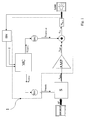
- figure 1 shows an electronic circuit 1 realised according to the invention for the automatic calibration of pressure sensors.
- a pressure sensor/transductor S usually but not exclusively realised by means of a membrane sensitive element and an associated Wheatstone bridge is installed in a measuring chamber SOURCE, wherein a pressure variation ⁇ p occurs, generated, for example, by a hydraulic cylinder or a press or a machine tool, etc; such a sensor is described for example in US patent no. 6,450,038 by the same Applicant.
- Such sensor S detects said pressure variation ⁇ p and generates a corresponding signal S SENS , typicallya voltage value to be amplified.
- the signal S SENS is amplified by a signal amplifier AMP, cascade-connected with the sensor S outputting an amplified signal S AMP .
- an output signal S OUT is emitted by the circuit 1 in correspondence with an output terminal N OUT .
- the output signal S OUT serves as output signal of the circuit 1 and as input signal of a user device LOAD.
- the circuit 1 comprises a microprocessor MC.
- Such microprocessor is interposed between the signal S and the output terminal N OUT .
- the microprocessor MC operates as a supervisor on an analogue chain comprising the sensor S and the amplifier AMP. Its purpose is to amplify the signal S SENS coming from the sensor S, in order to output the high level signal S OUT , typicallycomprised between 0 and 10 V in voltage and between 4 and 20 mA in current, to be supplied to the user device LOAD.
- the microprocessor MC allows configuration parameter values of the circuit 1 to be automatically regulated; more precisely, it allows to
- the regulation of said parameters occurs according to the values taken by the circuit output signal S OUT , acquired by an automatic data acquisition device SIN, outside the sensor.
- Such automatic device is preferably, but not exclusively, interposed between the output terminal N OUT of the circuit 1 and the microprocessor MC, it being possible however to implement it in the microprocessor MC itself.
- the device SIN receives at the input the output signal S OUT of the circuit 1 and it emits a signal S MC at the input of the microprocessor MC allowing the regulations to be performed.
- the microprocessor MC serving as an interface between Nout and S, is thus apt to vary the sensor electric power supply, more particularly a supply voltage Vsupply of the sensor S so that the noise-free output signal S OUT is generated.
- the microprocessor MC is capable of applying predetermined voltage values to the sensor S.
- the regulation occurs without any manual calibration intervention by external operators.
- the microprocessor MC Based on the information contained in the received signal S MC , the microprocessor MC emits a first calibration signal S CONFIG1 and a second signal S CONFIG2 ; the signal S CONFIG1 is applied at the input of the sensor S, in order to vary the supply voltage Vsupply thereof while the signal S CONFIG2 is applied at the input of an adder node ((+)) to regulate the value of the amplified signal S AMP ; the adder node ((+)) is inserted between the output of the signal amplifier AMP and the output terminal N OUT of the circuit 1. This operation is performed only once in the factory when calibrating the device.
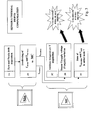
- Figure 2 shows a block diagram of the various steps of the calibration method of the sensor S, which are realized by the calibration of the sensor offset and gain values, such values being calculated according to the value taken by the signal S OUT outputted by the circuit 1 in the sensor S rest state and at the full scale value, respectively.
- the calibration operations are performed in an open loop by means of device SIN in the steps 2A and 2B and of the microprocessor MC in the steps 2C and 2D.
- the sensor S is in the rest position; particularly, in pressure sensors, this results in the detection of a null pressure; under these conditions, as shown in the step 2A in the figure, the automatic detection device SIN acquires the output signal S OUT from the circuit 1 representing the zero point of the sensor S.
- the sensor S is then brought to the full scale value thereof and the automatic detection device SIN, still with reference to the step 2A in the figure, acquires the output signal SOUT from the circuit 1.
- the automatic detection device SIN transfers in series to the microprocessor MC, by means of the signal S MC , the regulation coefficients of the zero and full scale signal represented by the values S ZERO and S FSCALA , respectively.
- the microprocessor MC operates on a supply voltage Vsupply of the sensor S by means of the signal S CONFIG1 ; such signal is of the digital type, for example PWM and it varies according to the full scale coefficient S FSCALA received by means of the signal S MC by the microprocessor MC in the step 2b.
- the signal S CONFIG1 is converted, by means of a digital to analogue converter DA1, for example a filter in the case of the signal PWM, into the analogue supply signal Vsupply; particularly, but not exclusively, such supply signal is represented by a voltage.
- a digital to analogue converter DA1 for example a filter in the case of the signal PWM, into the analogue supply signal Vsupply; particularly, but not exclusively, such supply signal is represented by a voltage.
- the microprocessor MC operating on the supply voltage Vsupply of the sensor S calibrates the gain value of the sensor S.
- the microprocessor MC operates on the adder node (+), by means of the signal S CONFIG2 ; such signal also, like S CONFIG1 , is of the digital type, for example PWM , but it varies according to the zero coefficient S ZERO received by means of the signal S MC , by the microprocessor MC in the step 2B.
- the signal S CONFIG1 is converted, by means of a digital to analogue converter DA2, for example a filter in the case of the signal PWM, into the analogue signal S CONFIG1_AN .
- a digital to analogue converter DA2 for example a filter in the case of the signal PWM
- the microprocessor MC adding a value S ZERO_ANALOG of the signal S CONFIG2_AN to the value S 1 of the amplified signal S AMP outputted by the amplifier AMP, regulates the offset value S OFFSET of the signal S OUT outputted by the sensor S.
- Figure 3 shows a block diagram of the various steps composing the thermal drift compensation operation of the sensor S.
- This compensation is performed in open loop, in the steps 3A and 3B, by the automatic detection device SIN and, in the steps 3C to 3E by the microprocessor MC.
- the automatic detection device SIN acquires some values corresponding to the sensor zero and full-scale thermal drift.
- the automatic detection device SIN transfers to the microprocessor MC, by means of the signal S MC , the compensation coefficients of the zero and full scale thermal drifts represented by the values T ZERO and T FSCALA , respectively.
- the microprocessor MC records a temperature T typical of the environment wherein it is operating and, according to the detected temperature T value and to the values T ZERO e T FSCALA received in the step 3B, it performs regulation and compensation operations of the sensor S and of the circuit 1 in general.
- the microprocessor MC operates on the supply voltage Vsupply of the sensor S by means of the signal S CONFIG1 ; such signal is of the digital type, for example PWM and it varies according to the value T FSCALA received by means of the signal S MC by the microprocessor MC in the step 3B.
- the signal S CONFIG1 is converted, by means of a digital to analogue converter DA1, for example a filter in the case of a signal PWM, into the analogue supply signal Vsupply.
- a digital to analogue converter DA1 for example a filter in the case of a signal PWM
- the variation of the supply voltage Vsupply of the sensor S allows the compensation of the full-scale thermal drifts.
- the microprocessor MC operates on the adder node (+), by means of the digital signal S CONFIG2 , for example PWM, but it varies according to the zero value T ZERO received by means of the signal S MC , by the microprocessor MC in the step 2b.
- the signal S CONFIG2 is converted, by means of a digital to analogue converter DA2, for example a filter in the case of a signal PWM, into the analogue signal S CONFIG2_AN .
- DA2 digital to analogue converter
- the microprocessor MC by adding a value T ZERO_ANALOG of the signal S CONFIG2_AN to the value S2 of the amplified signal S AMP outputted by the amplifier AMP, generates a value S DERZERO of the signal S OUT outputted by the sensor S, which compensates the zero drifts outputted by the sensor S.
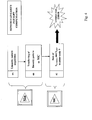
- Figure 4 shows a block diagram of the various steps composing the compensation of the non linearity error operation of the sensor S.
- steps 4A and 4B such compensation is performed in a closed loop by means of the automatic detection device SIN, while in the steps 4C and 4D, still in a closed loop, it is performed by the microprocessor MC.
- the compensation operation is performed with the sensor S operating, i.e. constantly during the operation.
- the automatic detection device SIN acquires the real linearity pattern of the sensor S by comparing Sout with the output pattern of an ideal reference device.
- the automatic detection device SIN transfers to the microprocessor MC, by means of the signal S MC , the correction coefficients of the detected pattern calculated according to the deviation between the real and the ideal pattern.
- the microprocessor monitors the output signal S OUT of the circuit 1 and it operates on the adder node (mixer point) (+), by means of the digital signal, for example PWM, S CONFIG2 , as reported in the step 4C; such signal varies according to the values taken by the ideal linearity pattern received by the microprocessor MC in the step 4B.
- the signal S CONFIG2 is converted, by means of the digital to analogue converter DA2, for example a filter in the case of a signal PWM, into the analogue signal S CONFIG2_AN .
- the microprocessor MC by adding a value T ERR_LIN of the signal S CONFIG2_AN to the value S3 of the amplified signal S AMP outputted by the amplifier AMP, generates a value T ERR of the signal S OUT , outputted by the sensor S, which compensates the linearity error of the sensor S.
- the circuit with the microprocessor MC and the relative calibration method allows the offset and gain values of a sensor to be automatically regulated , as well as the thermal drifts and the non linearity effects to be compensated.
Landscapes
- Physics & Mathematics (AREA)
- General Physics & Mathematics (AREA)
- Chemical & Material Sciences (AREA)
- Analytical Chemistry (AREA)
- Nonlinear Science (AREA)
- Engineering & Computer Science (AREA)
- Technology Law (AREA)
- Measuring Fluid Pressure (AREA)
Abstract
- a signal amplifier (AMP) interposed between the pressure sensor (S) and the output terminal (NOUT) of the circuit (1)
- a microprocessor (MC) connected to the pressure sensor (S) and to the output terminal (NOUT) and receiving at the input a signal (SMC) from an automatic data acquisition device (SIN) to automatically calibrate the sensor (S) by varying the electric power supply thereof or applying predetermined voltage values.
Description
- The present invention relates to an electronic circuit for the automatic calibration of pressure sensor devices.
- The invention relates also to a method for calibrating a pressure sensor device of said type.
- The invention relates particularly, but not exclusively, to an electronic circuit for the automatic calibration of pressure sensor devices, wherein the calibration occurs by means of digital signals and the following description is made with reference to this field of application for convenience of illustration only.
- As it is well known, a sensor device detects a physical quantity or a variation thereof in a predetermined environment and turns it into another physical quantity, generally an electrical quantity, for processing in user devices.
- In other words, and with non limiting reference to pressure sensor devices, a pressure sensor detects a value for the pressure exerted in a chamber, for example by a hydraulic cylinder, a press, a machine tool or the like and it turns it into an output signal, such as a voltage or current electric signal, for a user device. The user device may be a control loop for the opening of a water pipe gate valve, or an alarm signal emitting circuit for the detection of a pressure higher than the one permitted in a plant, etc.
- The signal produced is conveniently amplified before being exploited in a user device.
- The resulting amplified signal must be as much noise-free as possible for a correct transmission of the detected signal.
- To this purpose, the sensor must be calibrated according to different configuration parameters and owing to the continuous variations of the output signals.
- More precisely, sensor offset and gain values must be calibrated, thermal drift compensations and, if necessary, linearity corrections on the signals produced by the sensor, must be performed.
- With reference thereto and hereafter in the description, a sensor "zero point" will mean a reference value, from which the input physical quantity is measured.
- Moreover, the expression "thermal drifts" will mean the system temperature variations, which can causea zero point variation, which generates undesired variations in the circuit output values.
- Moreover, "linearity errors" will mean the deviations between the real pattern of the sensor operation and the ideal pattern; such errors are expressed as a percentage of a value called "full scale", which represents the upper limit of the sensor measuring range. Linearity corrections are performed to minimize the linearity error.
- A first known embodiment provides the control of two configuration parameters, the offset value and the sensor gain, by means of precision potentiometers, i.e. analogue trimmers.
- Although advantageous under several aspects, this embodiment has several drawbacks.
- For calibrating an analogue trimmer, the intervention of an operator is required; moreover, manual calibration of a trimmer is intrinsically subject to errors and inaccuracies and does not allow the circuit calibration performance to be stable in time.
- Moreover, by using analogue trimmers, it is not possible to obtain linearised signals from the sensor.
- A second known embodiment, instead, provides the use of digital circuits such as the so-called ASIC (Application Specific Integrated Circuit) or FPGA (Field-programmable gate array).
- These circuits allow higher performance precision and stability in time compared to analogue trimmers, automatic calibration and they allow linearity corrections on the signals produced by the sensor.
- Although advantageous for the mentioned aspects, these circuits also are not without drawbacks.
- In fact, they are made to meet the technical requirements of particular and specific applications; they are thus purpose-made integrated circuits.
- Consequently, the realisation has considerable costs, resulting convenient only for large-scale productions; the choice of ASIC and FPGA is thus not a good solution for limited-series productions.
- The technical problem underlying the present invention is to provide a circuit for the automatic calibration of pressure sensors, having such structural and functional features as to be easily used in several and different applications and not realised for a particular application, overcoming the limitations of the circuits realised according to the prior art.
- The solution idea underlying the present invention is to use a microprocessor receiving calibration parameters and accordingly varying the sensor supply voltage or applying a predetermined voltage value, in order to enablean automatic calibration of the sensor.
- Based on this solution idea, the technical problem is solved by a calibration circuit of the type previously indicated and defined in the characterising part of claim 1.
- The problem is also solved by a calibration method of the type previously indicated and defined in the characterising part of claim 7.
- The features and advantages of the device according to the invention will become apparent from the following description of an embodiment thereof given by way of an indicative and non limiting example with reference to the attached drawings.
- In such drawings:
- Figure 1 shows a diagram of an electronic circuit for the automatic calibration of pressure sensors, according to the present invention.
- Figure 2 to 4 show block diagrams of the method operative steps, according to the present invention.
- With reference to such figures, figure 1 shows an electronic circuit 1 realised according to the invention for the automatic calibration of pressure sensors.
- In such figure, a pressure sensor/transductor S, usually but not exclusively realised by means of a membrane sensitive element and an associated Wheatstone bridge is installed in a measuring chamber SOURCE, wherein a pressure variation Δp occurs, generated, for example, by a hydraulic cylinder or a press or a machine tool, etc; such a sensor is described for example in US patent no. 6,450,038 by the same Applicant.
- Such sensor S detects said pressure variation Δp and generates a corresponding signal SSENS, typicallya voltage value to be amplified. The signal SSENS is amplified by a signal amplifier AMP, cascade-connected with the sensor S outputting an amplified signal SAMP.
- Generally, an output signal SOUT is emitted by the circuit 1 in correspondence with an output terminal NOUT. The output signal SOUT serves as output signal of the circuit 1 and as input signal of a user device LOAD.
- Advantageously, according to the invention, the circuit 1 comprises a microprocessor MC.
- Such microprocessor is interposed between the signal S and the output terminal NOUT.
- The microprocessor MC operates as a supervisor on an analogue chain comprising the sensor S and the amplifier AMP. Its purpose is to amplify the signal SSENS coming from the sensor S, in order to output the high level signal SOUT, typicallycomprised between 0 and 10 V in voltage and between 4 and 20 mA in current, to be supplied to the user device LOAD.
- Advantageously, the microprocessor MC allows configuration parameter values of the circuit 1 to be automatically regulated; more precisely, it allows to
- calibrate the sensor S or, in other words, set the sensor offset and gain value;
- compensate the sensor S thermal drifts S;
- Compensate the sensor S linearity curves;
- The regulation of said parameters occurs according to the values taken by the circuit output signal S OUT , acquired by an automatic data acquisition device SIN, outside the sensor. Such automatic device is preferably, but not exclusively, interposed between the output terminal NOUT of the circuit 1 and the microprocessor MC, it being possible however to implement it in the microprocessor MC itself. The device SIN receives at the input the output signal SOUT of the circuit 1 and it emits a signal SMC at the input of the microprocessor MC allowing the regulations to be performed.
- Advantageously according to the invention, the microprocessor MC, serving as an interface between Nout and S, is thus apt to vary the sensor electric power supply, more particularly a supply voltage Vsupply of the sensor S so that the noise-free output signal SOUT is generated.
- Alternatively, the microprocessor MC is capable of applying predetermined voltage values to the sensor S.
- Advantageously, according to the present invention, the regulation occurs without any manual calibration intervention by external operators.
- Based on the information contained in the received signal SMC, the microprocessor MC emits a first calibration signal SCONFIG1 and a second signal SCONFIG2; the signal SCONFIG1 is applied at the input of the sensor S, in order to vary the supply voltage Vsupply thereof while the signal SCONFIG2 is applied at the input of an adder node ((+)) to regulate the value of the amplified signal SAMP; the adder node ((+)) is inserted between the output of the signal amplifier AMP and the output terminal NOUT of the circuit 1. This operation is performed only once in the factory when calibrating the device.
- The steps of the calibration method of the sensor S according to the invention will now be described, with specific reference to figures 2, 3 and 4.
- Figure 2 shows a block diagram of the various steps of the calibration method of the sensor S, which are realized by the calibration of the sensor offset and gain values, such values being calculated according to the value taken by the signal SOUT outputted by the circuit 1 in the sensor S rest state and at the full scale value, respectively. The calibration operations are performed in an open loop by means of device SIN in the
steps steps - Initially, the sensor S is in the rest position; particularly, in pressure sensors, this results in the detection of a null pressure; under these conditions, as shown in the
step 2A in the figure, the automatic detection device SIN acquires the output signal SOUT from the circuit 1 representing the zero point of the sensor S. - The sensor S is then brought to the full scale value thereof and the automatic detection device SIN, still with reference to the
step 2A in the figure, acquires the output signal SOUT from the circuit 1. - In the
step 2B of the figure, the automatic detection device SIN transfers in series to the microprocessor MC, by means of the signal SMC, the regulation coefficients of the zero and full scale signal represented by the values SZERO and SFSCALA, respectively. - As shown in the
step 2C of figure 2, the microprocessor MC operates on a supply voltage Vsupply of the sensor S by means of the signal SCONFIG1; such signal is of the digital type, for example PWM and it varies according to the full scale coefficient SFSCALA received by means of the signal SMC by the microprocessor MC in the step 2b. - Before feeding said sensor S, the signal SCONFIG1 is converted, by means of a digital to analogue converter DA1, for example a filter in the case of the signal PWM, into the analogue supply signal Vsupply; particularly, but not exclusively, such supply signal is represented by a voltage.
- Advantageously according to the invention, the microprocessor MC, operating on the supply voltage Vsupply of the sensor S calibrates the gain value of the sensor S.
- Moreover, the microprocessor MC, as shown in the
step 2D of the figure, operates on the adder node (+), by means of the signal SCONFIG2; such signal also, like SCONFIG1, is of the digital type, for example PWM , but it varies according to the zero coefficient SZERO received by means of the signal SMC, by the microprocessor MC in thestep 2B. - Before operating on the adder node (+), the signal SCONFIG1 is converted, by means of a digital to analogue converter DA2, for example a filter in the case of the signal PWM, into the analogue signal SCONFIG1_AN.
- Advantageously according to the invention, the microprocessor MC, adding a value SZERO_ANALOG of the signal SCONFIG2_AN to the value S 1 of the amplified signal SAMP outputted by the amplifier AMP, regulates the offset value SOFFSET of the signal SOUT outputted by the sensor S.
- The
steps 2A-2D previously described are performed only once in the factory when calibrating the sensor. - Figure 3 shows a block diagram of the various steps composing the thermal drift compensation operation of the sensor S.
- This compensation is performed in open loop, in the
steps steps 3C to 3E by the microprocessor MC. - As described in the
step 3A, the automatic detection device SIN acquires some values corresponding to the sensor zero and full-scale thermal drift. - In the
step 3B of the figure, the automatic detection device SIN transfers to the microprocessor MC, by means of the signal SMC, the compensation coefficients of the zero and full scale thermal drifts represented by the values TZERO and TFSCALA, respectively. - During the normal operation thereof, the microprocessor MC recordsa temperature T typical of the environment wherein it is operating and, according to the detected temperature T value and to the values TZERO e TFSCALA received in the
step 3B, it performs regulation and compensation operations of the sensor S and of the circuit 1 in general. - As reported in the
step 3D in figure 3, the microprocessor MC operates on the supply voltage Vsupply of the sensor S by means of the signal SCONFIG1; such signal is of the digital type, for example PWM and it varies according to the value TFSCALA received by means of the signal SMC by the microprocessor MC in thestep 3B. - Before feeding said sensor S, the signal SCONFIG1 is converted, by means of a digital to analogue converter DA1, for example a filter in the case of a signal PWM, into the analogue supply signal Vsupply.
- Advantageously, according to the invention the variation of the supply voltage Vsupply of the sensor S allows the compensation of the full-scale thermal drifts.
- Moreover, the microprocessor MC, as reported in the
step 3E of the figure, operates on the adder node (+), by means of the digital signal SCONFIG2, for example PWM, but it varies according to the zero value TZERO received by means of the signal SMC, by the microprocessor MC in the step 2b. - Before actingon the adder node (mixer point) (+), the signal SCONFIG2 is converted, by means of a digital to analogue converter DA2, for example a filter in the case of a signal PWM, into the analogue signal SCONFIG2_AN.
- Advantageously, according to the invention, the microprocessor MC, by adding a value TZERO_ANALOG of the signal SCONFIG2_AN to the value S2 of the amplified signal SAMP outputted by the amplifier AMP, generates a value SDERZERO of the signal SOUT outputted by the sensor S, which compensates the zero drifts outputted by the sensor S. Figure 4 shows a block diagram of the various steps composing the compensation of the non linearity error operation of the sensor S.
- In the
steps steps 4C and 4D, still in a closed loop, it is performed by the microprocessor MC. - The compensation operation, as a whole, is performed with the sensor S operating, i.e. constantly during the operation.
- As reported in the
step 4A, the automatic detection device SIN acquires the real linearity pattern of the sensor S by comparing Sout with the output pattern of an ideal reference device. - In the
step 4B of the figure, the automatic detection device SIN transfers to the microprocessor MC, by means of the signal SMC, the correction coefficients of the detected pattern calculated according to the deviation between the real and the ideal pattern. - The microprocessor monitors the output signal SOUT of the circuit 1 and it operates on the adder node (mixer point) (+), by means of the digital signal, for example PWM, SCONFIG2 , as reported in the
step 4C; such signal varies according to the values taken by the ideal linearity pattern received by the microprocessor MC in thestep 4B. - Before operating on the adder node (mixer point) (+), the signal SCONFIG2 is converted, by means of the digital to analogue converter DA2, for example a filter in the case of a signal PWM, into the analogue signal SCONFIG2_AN.
- Advantageously according to the invention, the microprocessor MC, by adding a value TERR_LIN of the signal SCONFIG2_AN to the value S3 of the amplified signal SAMP outputted by the amplifier AMP, generates a value TERR of the signal SOUT, outputted by the sensor S, which compensates the linearity error of the sensor S.
- In conclusion, the circuit with the microprocessor MC and the relative calibration method, according to the invention, allows the offset and gain values of a sensor to be automatically regulated , as well as the thermal drifts and the non linearity effects to be compensated.
- These operations occur without any manual calibration intervention by external operators.
Claims (11)
- An electronic circuit (1) for the automatic calibration of pressure sensor devices, of the type associated to a pressure sensor (S) for detecting pressure variations in a closed environment, characterized in that it comprises:a signal amplifier (AMP) inserted between said pressure sensor (S) and an output terminal (NOUT) of said circuit (1);a microprocessor (MC) connected to said pressure sensor (S) and to said output terminal (NOUT) and receiving at the input a signal (SMC) from an automatic data acquisition device (SIN) to automatically calibrate said sensor (S) by varying the electric power supply thereof or applying predetermined voltage values.
- A circuit according to claim 1, characterized in that it further comprises an adder node ((+)) at the output of said amplifier (AMP) and receiving a signal outputted by the microprocessor (MC).
- A circuit according to claim 1 characterized in that said automatic data acquisition device (SIN) has input connected to said output terminal (NOUT) and output connected to the input of the microprocessor (MC).
- A circuit according to claim 1 characterized in that it comprises a digital to analogue converter (DA1), or a filter, interposed between said microprocessor (MC) and said sensor (S).
- A circuit according to claim 2 characterized in that it comprises a digital to analogue converter (DA2), or a filter, interposed between said microprocessor (MC) and said adder node ((+)).
- A circuit according to claim 1, wherein said electric power supply is a supply voltage (Vsupply).
- An automatic calibration method of a pressure sensor (S) for detecting pressure variations in a closed environment, characterized in that:it provides an electronic calibration circuit (1) comprising a microprocessor (MC) connected to the sensor (S);it picks up an amplified electric signal (SOUT) outputted by the sensor (S);it converts and transfers an input signal (SMC) to the microprocessor (MC);it automatically calibrates said sensor (S) by varying the electric power supply thereof or applying predetermined voltage values.
- Method according to claim 7 characterized in that the automatic calibration of the sensor (S) includes a calibration of the offset and gain values of said sensor (S).
- Method according to claim 7, characterized in that the automatic calibration of the sensor (S) includes the steps of:acquiring by means of an automatic acquisition device (SIN), receiving at the input said electric signal (S OUT ), zero (SZERO) and full-scale (SFSCALA) information of said sensor (S);transfering the information acquired by said acquisition device (SIN) to said microprocessor (MC);varying, by means of said microprocessor (MC), the supply voltage (Vsupply) of said sensor (S), by means of a digital signal (for example PWM) (SCONFIG1) a function of said full-scale information (SFSCALA), to calibrate the gain value of said sensor (S);adding in an adder node ((+)) a second signal PWM (SCONFIG2), a function of said zero information (SZERO), with said amplified signal (SAMP) to calibrate the offset value of said sensor (S).
- Automatic calibration method of a pressure sensor (S) for detecting pressure variations in a closed environment, characterized in that:it provides an electronic calibration circuit (1) di calibrazione comprising a microprocessor (MC) connected to the sensor (S);it picks up an amplified electric signal (SOUT) outputted by the sensor (S);it converts and transfers an input signal (SMC) to the microprocessor (MC);it detects the temperature (T) of the sensor operating environment;it automatically calibrates said sensor (S) by varying the electric power supply thereof or applying predetermined voltage values, compensating the thermal drift thereof.
- Automatic calibration method of a pressure sensor (S) for detecting pressure variations in a closed environment, characterized in that:it provides an electronic calibration circuit (1) comprising a microprocessor (MC) connected to the sensor (S);it constantly picks up an amplified electric signal (SOUT) outputted by the sensor (S);it converts and transfers an input signal (SMC) of the microprocessor (MC);it acquires data related to a sensor linearity pattern by means of an automatic data acquisition device (SIN);it automatically calibrates said sensor (S) by varying the electric power supply thereof or applying predetermined voltage values, compensating the linearity thereof.
Priority Applications (1)
| Application Number | Priority Date | Filing Date | Title |
|---|---|---|---|
| EP04425396A EP1602907A1 (en) | 2004-05-31 | 2004-05-31 | Automatic sensor correction with feedback microprocessor |
Applications Claiming Priority (1)
| Application Number | Priority Date | Filing Date | Title |
|---|---|---|---|
| EP04425396A EP1602907A1 (en) | 2004-05-31 | 2004-05-31 | Automatic sensor correction with feedback microprocessor |
Publications (1)
| Publication Number | Publication Date |
|---|---|
| EP1602907A1 true EP1602907A1 (en) | 2005-12-07 |
Family
ID=34932528
Family Applications (1)
| Application Number | Title | Priority Date | Filing Date |
|---|---|---|---|
| EP04425396A Withdrawn EP1602907A1 (en) | 2004-05-31 | 2004-05-31 | Automatic sensor correction with feedback microprocessor |
Country Status (1)
| Country | Link |
|---|---|
| EP (1) | EP1602907A1 (en) |
Cited By (18)
| Publication number | Priority date | Publication date | Assignee | Title |
|---|---|---|---|---|
| WO2007126510A2 (en) | 2006-03-29 | 2007-11-08 | Tekscan, Inc. | Control circuit for pressure responsive sensor array and related methods |
| WO2012004370A1 (en) | 2010-07-07 | 2012-01-12 | Delphi Technologies, Inc. | Algorithm for detecting activation of a push button |
| EP2629075A1 (en) * | 2012-02-20 | 2013-08-21 | Sony Ericsson Mobile Communications AB | Method for determining a sensor value |
| WO2013135661A1 (en) * | 2012-03-13 | 2013-09-19 | Robert Bosch Gmbh | Pressure-measuring assembly |
| CN103424205A (en) * | 2012-05-15 | 2013-12-04 | E.G.O.电气设备制造股份有限公司 | Temperature measuring device, electric appliance having such a temperature measuring device and method for temperature measuring |
| CN103604560A (en) * | 2013-11-06 | 2014-02-26 | 苏州贝克微电子有限公司 | Pressure sensor with automatic reference |
| CN103712733A (en) * | 2012-09-28 | 2014-04-09 | 罗斯蒙德公司 | Remote Seal Process Pressure Measurement System |
| CN103808454A (en) * | 2014-02-27 | 2014-05-21 | 北京航空航天大学 | Method for automatic calibration of pressure sensor |
| US20140311138A1 (en) * | 2013-04-22 | 2014-10-23 | Illinois Tool Works Inc. | Systems and methods for detecting a type of hydraulic device |
| EP2365289A3 (en) * | 2010-03-09 | 2014-11-19 | Alfmeier Präzision AG Baugruppen und Systemlösungen | Pressure sensor, valve assembly and method for its operation |
| CN104819805A (en) * | 2015-04-30 | 2015-08-05 | 郑州荣奇热电能源有限公司 | Automatic pressure verification device |
| CN109813472A (en) * | 2019-03-14 | 2019-05-28 | 湖南道达宇科技有限公司 | A kind of embedded load sensor |
| US20210131898A1 (en) * | 2019-10-31 | 2021-05-06 | DJ Instruments | Temperature compensation of strain gauge output |
| CN113375853A (en) * | 2021-06-09 | 2021-09-10 | 上海钧嵌传感技术有限公司 | Air pressure sensor module and calibration method thereof |
| CN114279482A (en) * | 2021-11-26 | 2022-04-05 | 山东云海国创云计算装备产业创新中心有限公司 | A kind of calibration method and system of transmission sensor |
| CN115427818A (en) * | 2020-04-21 | 2022-12-02 | 松下知识产权经营株式会社 | Sensor system, sensing method, and program |
| CN116203328A (en) * | 2023-04-06 | 2023-06-02 | 埃用仪器(苏州)有限公司 | Electric field sensor with self-calibration function |
| CN120846573A (en) * | 2025-09-22 | 2025-10-28 | 成都睿宝电子科技有限公司 | Automatic full-scale calibration circuit and calibration method based on Pirani vacuum transmitter |
Citations (6)
| Publication number | Priority date | Publication date | Assignee | Title |
|---|---|---|---|---|
| US4715003A (en) * | 1984-07-27 | 1987-12-22 | Keller Ag Fur Druckmesstechnik | Method for temperature compensation and measuring circuit therefor |
| US4765188A (en) * | 1986-11-24 | 1988-08-23 | Bourns Instruments, Inc. | Pressure transducer with integral digital temperature compensation |
| EP0319202A2 (en) * | 1987-11-30 | 1989-06-07 | Mettler-Toledo, Inc. | Compensated multiple load cell scale |
| WO1995018357A1 (en) * | 1993-12-30 | 1995-07-06 | Honeywell Inc. | Embedded programmable sensor calibration apparatus |
| EP0721099A2 (en) * | 1995-01-03 | 1996-07-10 | Motorola, Inc. | Sensor circuit and method for compensation |
| US20040045359A1 (en) * | 2002-09-06 | 2004-03-11 | Kurtz Anthony D. | Doubly compensated pressure transducer |
-
2004
- 2004-05-31 EP EP04425396A patent/EP1602907A1/en not_active Withdrawn
Patent Citations (6)
| Publication number | Priority date | Publication date | Assignee | Title |
|---|---|---|---|---|
| US4715003A (en) * | 1984-07-27 | 1987-12-22 | Keller Ag Fur Druckmesstechnik | Method for temperature compensation and measuring circuit therefor |
| US4765188A (en) * | 1986-11-24 | 1988-08-23 | Bourns Instruments, Inc. | Pressure transducer with integral digital temperature compensation |
| EP0319202A2 (en) * | 1987-11-30 | 1989-06-07 | Mettler-Toledo, Inc. | Compensated multiple load cell scale |
| WO1995018357A1 (en) * | 1993-12-30 | 1995-07-06 | Honeywell Inc. | Embedded programmable sensor calibration apparatus |
| EP0721099A2 (en) * | 1995-01-03 | 1996-07-10 | Motorola, Inc. | Sensor circuit and method for compensation |
| US20040045359A1 (en) * | 2002-09-06 | 2004-03-11 | Kurtz Anthony D. | Doubly compensated pressure transducer |
Cited By (29)
| Publication number | Priority date | Publication date | Assignee | Title |
|---|---|---|---|---|
| WO2007126510A3 (en) * | 2006-03-29 | 2007-12-21 | Tekscan Inc | Control circuit for pressure responsive sensor array and related methods |
| US7591165B2 (en) | 2006-03-29 | 2009-09-22 | Tekscan Incorporated | Control circuit for sensor array and related methods |
| WO2007126510A2 (en) | 2006-03-29 | 2007-11-08 | Tekscan, Inc. | Control circuit for pressure responsive sensor array and related methods |
| EP2365289A3 (en) * | 2010-03-09 | 2014-11-19 | Alfmeier Präzision AG Baugruppen und Systemlösungen | Pressure sensor, valve assembly and method for its operation |
| WO2012004370A1 (en) | 2010-07-07 | 2012-01-12 | Delphi Technologies, Inc. | Algorithm for detecting activation of a push button |
| US9322724B2 (en) | 2010-07-07 | 2016-04-26 | Delphi Technologies, Inc. | Algorithm for detecting activation of a push button |
| EP2629075A1 (en) * | 2012-02-20 | 2013-08-21 | Sony Ericsson Mobile Communications AB | Method for determining a sensor value |
| WO2013135661A1 (en) * | 2012-03-13 | 2013-09-19 | Robert Bosch Gmbh | Pressure-measuring assembly |
| CN103424205A (en) * | 2012-05-15 | 2013-12-04 | E.G.O.电气设备制造股份有限公司 | Temperature measuring device, electric appliance having such a temperature measuring device and method for temperature measuring |
| WO2014052140A3 (en) * | 2012-09-28 | 2014-09-18 | Rosemount Inc. | Remote seal process pressure measuring system |
| CN103712733A (en) * | 2012-09-28 | 2014-04-09 | 罗斯蒙德公司 | Remote Seal Process Pressure Measurement System |
| US9274018B2 (en) | 2012-09-28 | 2016-03-01 | Rosemount Inc. | Remote seal process pressure measuring system |
| US10001148B2 (en) | 2013-04-22 | 2018-06-19 | Illinois Tool Works Inc. | Systems and methods for detecting a type of hydraulic device |
| US20140311138A1 (en) * | 2013-04-22 | 2014-10-23 | Illinois Tool Works Inc. | Systems and methods for detecting a type of hydraulic device |
| US9835181B2 (en) * | 2013-04-22 | 2017-12-05 | Illinois Tool Works Inc. | Systems and methods for detecting a type of hydraulic device |
| CN103604560A (en) * | 2013-11-06 | 2014-02-26 | 苏州贝克微电子有限公司 | Pressure sensor with automatic reference |
| CN103808454A (en) * | 2014-02-27 | 2014-05-21 | 北京航空航天大学 | Method for automatic calibration of pressure sensor |
| CN104819805A (en) * | 2015-04-30 | 2015-08-05 | 郑州荣奇热电能源有限公司 | Automatic pressure verification device |
| CN109813472B (en) * | 2019-03-14 | 2023-11-24 | 衡通华创(北京)科技有限公司 | Embedded load sensor |
| CN109813472A (en) * | 2019-03-14 | 2019-05-28 | 湖南道达宇科技有限公司 | A kind of embedded load sensor |
| US20210131898A1 (en) * | 2019-10-31 | 2021-05-06 | DJ Instruments | Temperature compensation of strain gauge output |
| US11598686B2 (en) * | 2019-10-31 | 2023-03-07 | DJ Instruments | Temperature compensation of strain gauge output |
| CN115427818A (en) * | 2020-04-21 | 2022-12-02 | 松下知识产权经营株式会社 | Sensor system, sensing method, and program |
| CN113375853A (en) * | 2021-06-09 | 2021-09-10 | 上海钧嵌传感技术有限公司 | Air pressure sensor module and calibration method thereof |
| CN113375853B (en) * | 2021-06-09 | 2022-03-11 | 上海钧嵌传感技术有限公司 | Air pressure sensor module and calibration method thereof |
| CN114279482A (en) * | 2021-11-26 | 2022-04-05 | 山东云海国创云计算装备产业创新中心有限公司 | A kind of calibration method and system of transmission sensor |
| CN114279482B (en) * | 2021-11-26 | 2024-04-09 | 山东云海国创云计算装备产业创新中心有限公司 | Verification method and system for transmission sensor |
| CN116203328A (en) * | 2023-04-06 | 2023-06-02 | 埃用仪器(苏州)有限公司 | Electric field sensor with self-calibration function |
| CN120846573A (en) * | 2025-09-22 | 2025-10-28 | 成都睿宝电子科技有限公司 | Automatic full-scale calibration circuit and calibration method based on Pirani vacuum transmitter |
Similar Documents
| Publication | Publication Date | Title |
|---|---|---|
| JP3978238B2 (en) | Temperature compensation method for electro-pneumatic converter | |
| US5460049A (en) | Digitally-temperature-compensated strain-gauge pressure measuring apparatus | |
| US4798093A (en) | Apparatus for sensor compensation | |
| US7003417B2 (en) | Multiple calibration ranges stored in a process transmitter | |
| US20020082799A1 (en) | Measuring transducer with a corrected output signal | |
| US6974973B2 (en) | Apparatus for determining temperature of an active pixel imager and correcting temperature induced variations in an imager | |
| US4896282A (en) | Flow computer calibration technique | |
| US7033071B2 (en) | Method and apparatus for correcting sensor signal in temperature | |
| KR100620282B1 (en) | Systems and Methods for Linearizing Sensor Response | |
| US4362060A (en) | Displacement transducer | |
| CN1519566A (en) | Sensor device, measuring system and calibrating method | |
| DE60032220D1 (en) | CONTROL, CALIBRATION AND OPERATION OF A MICROBOLOMETERMATRIX | |
| KR101903907B1 (en) | Liquid leakage detector with improved reliability | |
| US6249753B1 (en) | Sensor signal conditioner with calibration | |
| US5361637A (en) | Temperature compensation circuitry employing a single temperature compensation element | |
| US6877379B2 (en) | Doubly compensated pressure transducer | |
| CN1963535A (en) | Automatic compensation of gain versus temperature | |
| US4679162A (en) | Wide dynamic range linear to log converter with microcomputer control | |
| US6279374B1 (en) | Compensating method and compensating apparatus for positioner | |
| EP0758739A1 (en) | Sensor module | |
| KR101101882B1 (en) | Hydraulic servo valve control device | |
| JPH01154614A (en) | Output power control circuit for transmitter | |
| JPH11118617A (en) | air conditioner | |
| JP2878602B2 (en) | Analog output device | |
| KR100867215B1 (en) | Correction method of sensor output voltage according to power output voltage error |
Legal Events
| Date | Code | Title | Description |
|---|---|---|---|
| PUAI | Public reference made under article 153(3) epc to a published international application that has entered the european phase |
Free format text: ORIGINAL CODE: 0009012 |
|
| AK | Designated contracting states |
Kind code of ref document: A1 Designated state(s): AT BE BG CH CY CZ DE DK EE ES FI FR GB GR HU IE IT LI LU MC NL PL PT RO SE SI SK TR |
|
| AX | Request for extension of the european patent |
Extension state: AL HR LT LV MK |
|
| 17P | Request for examination filed |
Effective date: 20060523 |
|
| AKX | Designation fees paid |
Designated state(s): AT BE BG CH CY CZ DE DK EE ES FI FR GB GR HU IE IT LI LU MC NL PL PT RO SE SI SK TR |
|
| RAP1 | Party data changed (applicant data changed or rights of an application transferred) |
Owner name: GEFRAN S.P.A. |
|
| 17Q | First examination report despatched |
Effective date: 20090821 |
|
| STAA | Information on the status of an ep patent application or granted ep patent |
Free format text: STATUS: THE APPLICATION IS DEEMED TO BE WITHDRAWN |
|
| 18D | Application deemed to be withdrawn |
Effective date: 20151201 |