EP1602776B1 - Steam iron - Google Patents
Steam iron Download PDFInfo
- Publication number
- EP1602776B1 EP1602776B1 EP05103698A EP05103698A EP1602776B1 EP 1602776 B1 EP1602776 B1 EP 1602776B1 EP 05103698 A EP05103698 A EP 05103698A EP 05103698 A EP05103698 A EP 05103698A EP 1602776 B1 EP1602776 B1 EP 1602776B1
- Authority
- EP
- European Patent Office
- Prior art keywords
- steam
- seating
- pipe
- iron
- ironing plate
- Prior art date
- Legal status (The legal status is an assumption and is not a legal conclusion. Google has not performed a legal analysis and makes no representation as to the accuracy of the status listed.)
- Expired - Lifetime
Links
- XEEYBQQBJWHFJM-UHFFFAOYSA-N Iron Chemical compound [Fe] XEEYBQQBJWHFJM-UHFFFAOYSA-N 0.000 title claims abstract description 41
- 229910052742 iron Inorganic materials 0.000 title claims abstract description 20
- 238000010409 ironing Methods 0.000 claims abstract description 28
- 239000007769 metal material Substances 0.000 claims abstract description 5
- 230000013011 mating Effects 0.000 claims description 5
- RTAQQCXQSZGOHL-UHFFFAOYSA-N Titanium Chemical compound [Ti] RTAQQCXQSZGOHL-UHFFFAOYSA-N 0.000 description 1
- 239000004411 aluminium Substances 0.000 description 1
- 229910052782 aluminium Inorganic materials 0.000 description 1
- XAGFODPZIPBFFR-UHFFFAOYSA-N aluminium Chemical compound [Al] XAGFODPZIPBFFR-UHFFFAOYSA-N 0.000 description 1
- 230000001419 dependent effect Effects 0.000 description 1
- 235000000396 iron Nutrition 0.000 description 1
- 229910001220 stainless steel Inorganic materials 0.000 description 1
- 239000010935 stainless steel Substances 0.000 description 1
- 239000010936 titanium Substances 0.000 description 1
- 229910052719 titanium Inorganic materials 0.000 description 1
Images


Classifications
-
- D—TEXTILES; PAPER
- D06—TREATMENT OF TEXTILES OR THE LIKE; LAUNDERING; FLEXIBLE MATERIALS NOT OTHERWISE PROVIDED FOR
- D06F—LAUNDERING, DRYING, IRONING, PRESSING OR FOLDING TEXTILE ARTICLES
- D06F75/00—Hand irons
- D06F75/38—Sole plates
-
- D—TEXTILES; PAPER
- D06—TREATMENT OF TEXTILES OR THE LIKE; LAUNDERING; FLEXIBLE MATERIALS NOT OTHERWISE PROVIDED FOR
- D06F—LAUNDERING, DRYING, IRONING, PRESSING OR FOLDING TEXTILE ARTICLES
- D06F75/00—Hand irons
- D06F75/08—Hand irons internally heated by electricity
- D06F75/10—Hand irons internally heated by electricity with means for supplying steam to the article being ironed
- D06F75/14—Hand irons internally heated by electricity with means for supplying steam to the article being ironed the steam being produced from water in a reservoir carried by the iron
- D06F75/18—Hand irons internally heated by electricity with means for supplying steam to the article being ironed the steam being produced from water in a reservoir carried by the iron the water being fed slowly, e.g. drop by drop, from the reservoir to a steam generator
Definitions
- the present invention concerns a steam iron comprising an ironing plate substantially pointed in shape, with steam seatings.
- Steam irons are known provided with a main body below which an ironing plate made of metal material is assembled, which is substantially pointed in shape.
- the purpose of the present invention is to achieve a steam iron which allows the user to select one or more specific parts of the ironing plate from which to deliver the steam.
- a steam iron according to the present invention comprises a main body and an ironing plate made of metal material, substantially pointed in shape and arranged below the main body.
- the ironing plate comprises a first steam seating, a second steam seating and valve means to distribute the steam, located between the two steam seatings, in order to selectively connect them.
- the first steam seating has a substantially triangular profile and comprises, on the bottom, a plurality of through holes open towards the bottom, able to allow the steam to exit from the front portion of the ironing plate;
- the second steam seating comprises a central sector, into which the steam is able to be introduced by steam generating members normally provided in the main body, and two lateral sectors arranged specular with respect to a median longitudinal axis of the ironing plate, and provided with a plurality of through holes, able to allow the steam to exit from corresponding median-rear lateral portions of the ironing plate.
- the valve means instead comprise a central body and a piston, the latter able to slide vertically inside the central body and commanded manually by a user, in order to define a first closed configuration of the valve means, wherein they allow the steam to exit only through the through holes of the first steam seating, and a second open configuration of the valve means, wherein they allow the steam to exit also through the through holes of the second seating.
- a steam iron 10 according to the present invention comprises a main body 11, and a pointed ironing plate 12, arranged below the main body 11.
- the latter can be of any known type.
- the ironing plate 12 ( figs. 2 , 3 and 4 ) is made of metal material, such as for example stainless steel, anodised aluminium, titanium or other, and comprises a substantially plane lower surface 15, a first steam seating 16, a second steam seating 17, a distribution valve 18 and a cover 19 arranged on the opposite side with respect to the lower surface 15 and above the two seatings 16 and 17, in such a manner as to define, in cooperation with the latter, two distinct steam chambers, respectively front 20 and rear 21.
- the cover 19 also comprises a plurality of connectors, denoted generally by the reference number 40, to which the various steam generation members, electric members and other known members are connected, provided inside the main body 11 of the iron 10 according to the invention.
- the ironing plate 12 also comprises, drowned therein, an electrical resistance 13, of a substantially known type, able to heat the lower surface 15 during the ironing operations.
- the first seating 16 has a substantially triangular profile and comprises on the bottom a plurality of through holes 23 open towards the bottom, able to allow the steam contained therein to exit in correspondence with a front portion of the lower surface 15 of the ironing plate 12.
- the second seating 17 comprises a central sector 25, into which the steam is introduced through the connectors 40, and two lateral sectors, respectively 26 and 27, arranged specular with respect to the median longitudinal axis X of the ironing plate 12, and able to be selectively connected to the central sector 25 by means of the distribution valve 18.
- the central sector 25 has a substantially rectangular profile and comprises a bottom surface provided with a plurality of pyramidal elements 29, able to increase the capacity for heat exchange thereof, and hence to improve the quality of the ironing done with the iron 10.
- Each of the two lateral sectors 26 and 27 comprises, on its own bottom surface, a row of through holes 30, able to allow the steam contained therein to exit from a corresponding median-rear lateral portion of the ironing plate 12.
- the distribution valve 18 is arranged between the two seatings 16 and 17, and comprises a central body 31 ( fig. 5 ) and a piston 32, the latter able to slide vertically inside a mating sliding seating 33 provided in the central body 31, and selectively commanded, for example by means of a command button 34 positioned on the upper portion of the main body 11.
- the central body 31 comprises a first pipe 35 and a second pipe 36.
- the first pipe 35 intersects with the sliding seating 33 in correspondence with a tapered portion 38 of the latter, and is able to connect the central sector 25 of the second seating 17 to the first seating 16.
- the second pipe 36 also intersects with the sliding seating 33, but in a direction substantially perpendicular to the first pipe 35, and is able to connect the central sector 25 to the two lateral sectors 26 and 27.
- the second pipe 36 intersects the sliding seating 33 at a greater distance from the lower surface 15 of the ironing plate 12 with respect to the first pipe 35, so that the two pipes 35 and 36 do not intersect, but are connected to each other only by a segment of the sliding seating 33.
- the piston 32 comprises a terminal portion 37 shaped substantially like a truncated cone with sizes mating with those of the tapered portion 38 of the sliding seating 33, and is associated with a helical spring 39 able to govern the vertical movement thereof.
- the commanded sliding of the piston 32 determines the selective configuration of the distribution valve 18 between a first closed position, wherein the helical spring 39 keeps the terminal portion 37 normally in cooperation with the mating tapered portion 38 of the sliding seating 33, so as to keep the first pipe 35 open and allow the passage of steam only from the central sector 25 to the first seating 16, and hence allow steam delivery exclusively from the front through holes 23; and a second open position, wherein the terminal portion 37 is detached from the tapered portion 38 so as to allow the passage of steam both through the first pipe 35 and also through the second pipe 36, and hence allow steam delivery also through the median-rear through holes 30.
- the user can selectively decide whether to deliver steam exclusively from the front portion of the ironing plate 12 or to deliver it also from the median-rear portion of the lower surface 15 of the ironing plate 12.
Landscapes
- Engineering & Computer Science (AREA)
- Textile Engineering (AREA)
- Irons (AREA)
- Organic Low-Molecular-Weight Compounds And Preparation Thereof (AREA)
Abstract
Description
- The present invention concerns a steam iron comprising an ironing plate substantially pointed in shape, with steam seatings.
- Steam irons are known provided with a main body below which an ironing plate made of metal material is assembled, which is substantially pointed in shape.
- Document
WO-A-97174872 - The purpose of the present invention is to achieve a steam iron which allows the user to select one or more specific parts of the ironing plate from which to deliver the steam.
- The Applicant has devised, tested and embodied this invention to overcome the shortcomings of the state of the art and to obtain these and other purposes and advantages.
- The present invention is set forth and characterized in the main claim, while the dependent claims describe other characteristics of the invention or variants to the main inventive idea.
- In accordance with the above purposes, a steam iron according to the present invention comprises a main body and an ironing plate made of metal material, substantially pointed in shape and arranged below the main body.
- The ironing plate comprises a first steam seating, a second steam seating and valve means to distribute the steam, located between the two steam seatings, in order to selectively connect them.
- The first steam seating has a substantially triangular profile and comprises, on the bottom, a plurality of through holes open towards the bottom, able to allow the steam to exit from the front portion of the ironing plate; the second steam seating comprises a central sector, into which the steam is able to be introduced by steam generating members normally provided in the main body, and two lateral sectors arranged specular with respect to a median longitudinal axis of the ironing plate, and provided with a plurality of through holes, able to allow the steam to exit from corresponding median-rear lateral portions of the ironing plate.
- The valve means instead comprise a central body and a piston, the latter able to slide vertically inside the central body and commanded manually by a user, in order to define a first closed configuration of the valve means, wherein they allow the steam to exit only through the through holes of the first steam seating, and a second open configuration of the valve means, wherein they allow the steam to exit also through the through holes of the second seating.
- In this way it is possible to select one or more portions of the ironing plate from which to deliver the steam.
- These and other characteristics of the present invention will become apparent from the following description of a preferential form of embodiment, given as a non-restrictive example with reference to the attached drawings wherein:
-
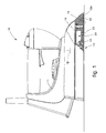
fig. 1 is a lateral view, partly in section, of a steam iron according to the present invention; -
fig. 2 is a view from above and uncovered of the ironing plate of the steam iron infig. 1 ; -
fig. 3 is a section from III to III offig. 2 ; -
fig. 4 is a section from IV to IV offig. 2 ; -
fig. 5 shows an enlarged detail offig. 3 . - With reference to
fig. 1 , asteam iron 10 according to the present invention comprises amain body 11, and apointed ironing plate 12, arranged below themain body 11. The latter can be of any known type. - The ironing plate 12 (
figs. 2 ,3 and 4 ) is made of metal material, such as for example stainless steel, anodised aluminium, titanium or other, and comprises a substantially planelower surface 15, afirst steam seating 16, asecond steam seating 17, adistribution valve 18 and acover 19 arranged on the opposite side with respect to thelower surface 15 and above the twoseatings front 20 and rear 21. Thecover 19 also comprises a plurality of connectors, denoted generally by thereference number 40, to which the various steam generation members, electric members and other known members are connected, provided inside themain body 11 of theiron 10 according to the invention. - The
ironing plate 12 also comprises, drowned therein, anelectrical resistance 13, of a substantially known type, able to heat thelower surface 15 during the ironing operations. - The
first seating 16 has a substantially triangular profile and comprises on the bottom a plurality of throughholes 23 open towards the bottom, able to allow the steam contained therein to exit in correspondence with a front portion of thelower surface 15 of theironing plate 12. - The
second seating 17 comprises acentral sector 25, into which the steam is introduced through theconnectors 40, and two lateral sectors, respectively 26 and 27, arranged specular with respect to the median longitudinal axis X of theironing plate 12, and able to be selectively connected to thecentral sector 25 by means of thedistribution valve 18. - The
central sector 25 has a substantially rectangular profile and comprises a bottom surface provided with a plurality ofpyramidal elements 29, able to increase the capacity for heat exchange thereof, and hence to improve the quality of the ironing done with theiron 10. - Each of the two
lateral sectors holes 30, able to allow the steam contained therein to exit from a corresponding median-rear lateral portion of theironing plate 12. - The
distribution valve 18 is arranged between the twoseatings fig. 5 ) and apiston 32, the latter able to slide vertically inside amating sliding seating 33 provided in thecentral body 31, and selectively commanded, for example by means of a command button 34 positioned on the upper portion of themain body 11. - The
central body 31 comprises afirst pipe 35 and asecond pipe 36. - The
first pipe 35 intersects with the slidingseating 33 in correspondence with atapered portion 38 of the latter, and is able to connect thecentral sector 25 of thesecond seating 17 to thefirst seating 16. Thesecond pipe 36 also intersects with thesliding seating 33, but in a direction substantially perpendicular to thefirst pipe 35, and is able to connect thecentral sector 25 to the twolateral sectors - To be more exact, the
second pipe 36 intersects the slidingseating 33 at a greater distance from thelower surface 15 of theironing plate 12 with respect to thefirst pipe 35, so that the twopipes seating 33. - The
piston 32 comprises aterminal portion 37 shaped substantially like a truncated cone with sizes mating with those of thetapered portion 38 of thesliding seating 33, and is associated with ahelical spring 39 able to govern the vertical movement thereof. - To be more exact, the commanded sliding of the
piston 32 determines the selective configuration of thedistribution valve 18 between a first closed position, wherein thehelical spring 39 keeps theterminal portion 37 normally in cooperation with the matingtapered portion 38 of the slidingseating 33, so as to keep thefirst pipe 35 open and allow the passage of steam only from thecentral sector 25 to thefirst seating 16, and hence allow steam delivery exclusively from the front throughholes 23; and a second open position, wherein theterminal portion 37 is detached from thetapered portion 38 so as to allow the passage of steam both through thefirst pipe 35 and also through thesecond pipe 36, and hence allow steam delivery also through the median-rear throughholes 30. - In this way, by acting on the command button 34 during the normal ironing steps, the user can selectively decide whether to deliver steam exclusively from the front portion of the
ironing plate 12 or to deliver it also from the median-rear portion of thelower surface 15 of theironing plate 12. - It is clear that, although the present invention has been described with reference to specific examples, a person of skill in the art shall certainly be able to achieve many other equivalent forms of steam iron, having the characteristics as set forth in the claims and hence all coming within the field of protection defined thereby.
Claims (8)
- Steam iron comprising a main body (11) and an ironing plate (12) made of metal material, substantially pointed in shape and arranged below said main body (11), said ironing plate (12) comprising a substantially plane lower surface (15), a first steam seating (16), a second steam seating (17) and whereby the user can selectively decide whether to deliver steam exclusively from the front portion or also from a median rear portion of said lover surface (15), characterized by a steam distribution valve means (18) arranged between said first steam seating (16) and said second steam seating (17), wherein said second steam seating (17) comprises a central sector (25), into which the steam is able to be introduced, and two lateral sectors, respectively (26, 27), arranged specular with respect to a median longitudinal axis (X) of said ironing plate (12), and able to be selectively connected to said central sector (25), wherein said steam distribution valve means (18) comprise a central body (31) and a piston (32), said piston (32) being able to slide vertically inside a mating sliding seating (33) provided inside said central body (31), and in that said central body (31) comprises a first pipe (35) intersecting with said sliding seating (33) in correspondence with a tapered portion (38) of said sliding seating (33), and able to connect together said central sector (25) of said second steam seating (17) and said first steam seating (16), and a second pipe (36), also intersecting said sliding seating (33), substantially perpendicular to the first pipe (35), and able to connect said central sector (25) to said two lateral sectors (26, 27),
- Steam iron as in claim 1, characterized in that said second pipe (36) intersects said sliding seating (33) at a greater distance from said lower surface (15), with respect to said first pipe (35), so that the two pipes (35, 36) do not intersect each other.
- Steam iron as in claim 1 or 2, characterized in that said piston (32) comprises a terminal portion (37) shaped substantially like a truncated cone and having sizes mating with those of said tapered portion (38) of said sliding seating (33), and is associated with a helical spring (39), able to govern the vertical movement thereof.
- Steam iron as in claim 3, characterized in that said steam distribution valve means (18) are able to be selectively configured between a first closed position, wherein said helical spring (39) keeps said terminal portion (37) normally in cooperation with said tapered portion (38), so as to keep said first pipe (35) open and allow the passage of steam only through said first pipe (35), and a second open position, wherein said terminal portion (37) is detached from said tapered portion (38), so as to allow the passage of steam both through said first pipe (35) and also through said second pipe (36).
- Steam iron as in claim 1, characterized in that it comprises covering means (19) arranged above said first steam seating (16) and said second steam seating (17), so as to define therewith corresponding distinct steam chambers (20, 21).
- Steam iron as in claim 1, characterized in that said first steam seating (16) has a substantially triangular profile and comprises on the bottom a plurality of through holes (23) open towards the bottom, able to allow the steam contained therein to exit from a front zone of said lower surface (15).
- Steam iron as in claim 1, characterized in that said central sector (25) has a substantially rectangular profile and comprises a bottom surface provided with a plurality of pyramidal elements (29) able to increase the heat exchange capacity with said lower surface (15).
- Steam iron as in claim 1, characterized in that each of said two lateral sectors (26, 27) comprises, on its own bottom surface, a plurality of through holes (30), able to allow the steam contained therein to exit from a corresponding median-rear lateral zone of said lower surface (15).
Applications Claiming Priority (2)
| Application Number | Priority Date | Filing Date | Title |
|---|---|---|---|
| ITUD20040087 | 2004-05-04 | ||
| IT000087A ITUD20040087A1 (en) | 2004-05-04 | 2004-05-04 | STEAM IRON |
Publications (2)
| Publication Number | Publication Date |
|---|---|
| EP1602776A1 EP1602776A1 (en) | 2005-12-07 |
| EP1602776B1 true EP1602776B1 (en) | 2010-12-15 |
Family
ID=34939673
Family Applications (1)
| Application Number | Title | Priority Date | Filing Date |
|---|---|---|---|
| EP05103698A Expired - Lifetime EP1602776B1 (en) | 2004-05-04 | 2005-05-03 | Steam iron |
Country Status (5)
| Country | Link |
|---|---|
| EP (1) | EP1602776B1 (en) |
| AT (1) | ATE491836T1 (en) |
| DE (1) | DE602005025281D1 (en) |
| ES (1) | ES2357896T3 (en) |
| IT (1) | ITUD20040087A1 (en) |
Family Cites Families (2)
| Publication number | Priority date | Publication date | Assignee | Title |
|---|---|---|---|---|
| US2041429A (en) * | 1932-10-31 | 1936-05-19 | Beardsley & Wolcott Mfg Compan | Electric sadiron |
| FR1128456A (en) * | 1955-03-24 | 1957-01-07 | Improvements to irons, in particular with steam production |
-
2004
- 2004-05-04 IT IT000087A patent/ITUD20040087A1/en unknown
-
2005
- 2005-05-03 ES ES05103698T patent/ES2357896T3/en not_active Expired - Lifetime
- 2005-05-03 AT AT05103698T patent/ATE491836T1/en not_active IP Right Cessation
- 2005-05-03 DE DE602005025281T patent/DE602005025281D1/en not_active Expired - Lifetime
- 2005-05-03 EP EP05103698A patent/EP1602776B1/en not_active Expired - Lifetime
Also Published As
| Publication number | Publication date |
|---|---|
| EP1602776A1 (en) | 2005-12-07 |
| ITUD20040087A1 (en) | 2004-08-04 |
| DE602005025281D1 (en) | 2011-01-27 |
| ATE491836T1 (en) | 2011-01-15 |
| ES2357896T3 (en) | 2011-05-03 |
Similar Documents
| Publication | Publication Date | Title |
|---|---|---|
| DE60015192T2 (en) | INTEGRATED SIDE WALL AND STITCH SURFACE CEILING FOR AN ECCENTRIC FLOOR CASTING OVEN (EBA) | |
| CN101355894B (en) | Lordosis support | |
| DE69315233T2 (en) | Gas stove burner with three concentric flames | |
| EP0162305B1 (en) | Apparatus for making espresso coffee | |
| US20120119486A1 (en) | Pressing device for a casting pipe at the spout of a metallurgical container | |
| US5592763A (en) | Steam discharge and steam distribution means | |
| WO1991017577A1 (en) | Float valve for container-filling systems, in particular systems for filling electric drive batteries | |
| WO2019048970A1 (en) | POT CARRIER, GAS BOILER AND METHOD FOR MANUFACTURING A POT CARRIER | |
| EP0604886B1 (en) | Electrically heated cooking vessel | |
| EP1602776A1 (en) | Steam iron | |
| EP3450852B1 (en) | Gas hob and gas range | |
| EP3990832B1 (en) | Pan support, gas cooking hob and method for producing a pan support | |
| DE69101121T2 (en) | Electric kettle. | |
| DE68902411T2 (en) | NOZZLE FOR FRESH LANCES. | |
| US4218966A (en) | Beverage brewer housing structure | |
| DE69103309T2 (en) | Improved brewing head unit for espresso coffee machines. | |
| EP0288684A2 (en) | Appliance for making hot beverages like coffee, tea or the like | |
| DE1155085B (en) | Steam iron | |
| DE69514701T2 (en) | Dining area | |
| DE202011004816U1 (en) | Valve set and radiator with such | |
| DE202016103202U1 (en) | Improved iron construction | |
| EP0233997B1 (en) | Heat exchanger, particularly for cooling process gas or for heating steam | |
| DE202017103005U1 (en) | Burning pellets heater | |
| DE4012951A1 (en) | STEAM IRON | |
| EP1269084A1 (en) | Cooking appliance |
Legal Events
| Date | Code | Title | Description |
|---|---|---|---|
| PUAI | Public reference made under article 153(3) epc to a published international application that has entered the european phase |
Free format text: ORIGINAL CODE: 0009012 |
|
| AK | Designated contracting states |
Kind code of ref document: A1 Designated state(s): AT BE BG CH CY CZ DE DK EE ES FI FR GB GR HU IE IS IT LI LT LU MC NL PL PT RO SE SI SK TR |
|
| AX | Request for extension of the european patent |
Extension state: AL BA HR LV MK YU |
|
| 17P | Request for examination filed |
Effective date: 20060605 |
|
| AKX | Designation fees paid |
Designated state(s): AT BE BG CH CY CZ DE DK EE ES FI FR GB GR HU IE IS IT LI LT LU MC NL PL PT RO SE SI SK TR |
|
| 17Q | First examination report despatched |
Effective date: 20070228 |
|
| GRAP | Despatch of communication of intention to grant a patent |
Free format text: ORIGINAL CODE: EPIDOSNIGR1 |
|
| GRAS | Grant fee paid |
Free format text: ORIGINAL CODE: EPIDOSNIGR3 |
|
| GRAA | (expected) grant |
Free format text: ORIGINAL CODE: 0009210 |
|
| AK | Designated contracting states |
Kind code of ref document: B1 Designated state(s): AT BE BG CH CY CZ DE DK EE ES FI FR GB GR HU IE IS IT LI LT LU MC NL PL PT RO SE SI SK TR |
|
| REG | Reference to a national code |
Ref country code: CH Ref legal event code: EP Ref country code: GB Ref legal event code: FG4D |
|
| REG | Reference to a national code |
Ref country code: IE Ref legal event code: FG4D |
|
| REF | Corresponds to: |
Ref document number: 602005025281 Country of ref document: DE Date of ref document: 20110127 Kind code of ref document: P |
|
| REG | Reference to a national code |
Ref country code: CH Ref legal event code: NV Representative=s name: MICHELI & CIE SA |
|
| REG | Reference to a national code |
Ref country code: NL Ref legal event code: T3 |
|
| PG25 | Lapsed in a contracting state [announced via postgrant information from national office to epo] |
Ref country code: LT Free format text: LAPSE BECAUSE OF FAILURE TO SUBMIT A TRANSLATION OF THE DESCRIPTION OR TO PAY THE FEE WITHIN THE PRESCRIBED TIME-LIMIT Effective date: 20101215 |
|
| REG | Reference to a national code |
Ref country code: ES Ref legal event code: FG2A Ref document number: 2357896 Country of ref document: ES Kind code of ref document: T3 Effective date: 20110503 |
|
| REG | Reference to a national code |
Ref country code: GR Ref legal event code: EP Ref document number: 20110400592 Country of ref document: GR Effective date: 20110412 |
|
| LTIE | Lt: invalidation of european patent or patent extension |
Effective date: 20101215 |
|
| PG25 | Lapsed in a contracting state [announced via postgrant information from national office to epo] |
Ref country code: SI Free format text: LAPSE BECAUSE OF FAILURE TO SUBMIT A TRANSLATION OF THE DESCRIPTION OR TO PAY THE FEE WITHIN THE PRESCRIBED TIME-LIMIT Effective date: 20101215 Ref country code: CY Free format text: LAPSE BECAUSE OF FAILURE TO SUBMIT A TRANSLATION OF THE DESCRIPTION OR TO PAY THE FEE WITHIN THE PRESCRIBED TIME-LIMIT Effective date: 20101215 Ref country code: AT Free format text: LAPSE BECAUSE OF FAILURE TO SUBMIT A TRANSLATION OF THE DESCRIPTION OR TO PAY THE FEE WITHIN THE PRESCRIBED TIME-LIMIT Effective date: 20101215 Ref country code: FI Free format text: LAPSE BECAUSE OF FAILURE TO SUBMIT A TRANSLATION OF THE DESCRIPTION OR TO PAY THE FEE WITHIN THE PRESCRIBED TIME-LIMIT Effective date: 20101215 Ref country code: BG Free format text: LAPSE BECAUSE OF FAILURE TO SUBMIT A TRANSLATION OF THE DESCRIPTION OR TO PAY THE FEE WITHIN THE PRESCRIBED TIME-LIMIT Effective date: 20110315 Ref country code: SE Free format text: LAPSE BECAUSE OF FAILURE TO SUBMIT A TRANSLATION OF THE DESCRIPTION OR TO PAY THE FEE WITHIN THE PRESCRIBED TIME-LIMIT Effective date: 20101215 |
|
| PG25 | Lapsed in a contracting state [announced via postgrant information from national office to epo] |
Ref country code: IS Free format text: LAPSE BECAUSE OF FAILURE TO SUBMIT A TRANSLATION OF THE DESCRIPTION OR TO PAY THE FEE WITHIN THE PRESCRIBED TIME-LIMIT Effective date: 20110415 Ref country code: PT Free format text: LAPSE BECAUSE OF FAILURE TO SUBMIT A TRANSLATION OF THE DESCRIPTION OR TO PAY THE FEE WITHIN THE PRESCRIBED TIME-LIMIT Effective date: 20110415 Ref country code: CZ Free format text: LAPSE BECAUSE OF FAILURE TO SUBMIT A TRANSLATION OF THE DESCRIPTION OR TO PAY THE FEE WITHIN THE PRESCRIBED TIME-LIMIT Effective date: 20101215 Ref country code: EE Free format text: LAPSE BECAUSE OF FAILURE TO SUBMIT A TRANSLATION OF THE DESCRIPTION OR TO PAY THE FEE WITHIN THE PRESCRIBED TIME-LIMIT Effective date: 20101215 Ref country code: BE Free format text: LAPSE BECAUSE OF FAILURE TO SUBMIT A TRANSLATION OF THE DESCRIPTION OR TO PAY THE FEE WITHIN THE PRESCRIBED TIME-LIMIT Effective date: 20101215 |
|
| PG25 | Lapsed in a contracting state [announced via postgrant information from national office to epo] |
Ref country code: PL Free format text: LAPSE BECAUSE OF FAILURE TO SUBMIT A TRANSLATION OF THE DESCRIPTION OR TO PAY THE FEE WITHIN THE PRESCRIBED TIME-LIMIT Effective date: 20101215 Ref country code: SK Free format text: LAPSE BECAUSE OF FAILURE TO SUBMIT A TRANSLATION OF THE DESCRIPTION OR TO PAY THE FEE WITHIN THE PRESCRIBED TIME-LIMIT Effective date: 20101215 Ref country code: RO Free format text: LAPSE BECAUSE OF FAILURE TO SUBMIT A TRANSLATION OF THE DESCRIPTION OR TO PAY THE FEE WITHIN THE PRESCRIBED TIME-LIMIT Effective date: 20101215 |
|
| PLBE | No opposition filed within time limit |
Free format text: ORIGINAL CODE: 0009261 |
|
| STAA | Information on the status of an ep patent application or granted ep patent |
Free format text: STATUS: NO OPPOSITION FILED WITHIN TIME LIMIT |
|
| PG25 | Lapsed in a contracting state [announced via postgrant information from national office to epo] |
Ref country code: DK Free format text: LAPSE BECAUSE OF FAILURE TO SUBMIT A TRANSLATION OF THE DESCRIPTION OR TO PAY THE FEE WITHIN THE PRESCRIBED TIME-LIMIT Effective date: 20101215 |
|
| 26N | No opposition filed |
Effective date: 20110916 |
|
| PG25 | Lapsed in a contracting state [announced via postgrant information from national office to epo] |
Ref country code: MC Free format text: LAPSE BECAUSE OF NON-PAYMENT OF DUE FEES Effective date: 20110531 |
|
| REG | Reference to a national code |
Ref country code: DE Ref legal event code: R097 Ref document number: 602005025281 Country of ref document: DE Effective date: 20110916 |
|
| REG | Reference to a national code |
Ref country code: IE Ref legal event code: MM4A |
|
| PG25 | Lapsed in a contracting state [announced via postgrant information from national office to epo] |
Ref country code: IE Free format text: LAPSE BECAUSE OF NON-PAYMENT OF DUE FEES Effective date: 20110503 |
|
| PGFP | Annual fee paid to national office [announced via postgrant information from national office to epo] |
Ref country code: CH Payment date: 20120523 Year of fee payment: 8 Ref country code: DE Payment date: 20120523 Year of fee payment: 8 Ref country code: NL Payment date: 20120531 Year of fee payment: 8 |
|
| PGFP | Annual fee paid to national office [announced via postgrant information from national office to epo] |
Ref country code: GB Payment date: 20120522 Year of fee payment: 8 Ref country code: GR Payment date: 20120530 Year of fee payment: 8 |
|
| PGFP | Annual fee paid to national office [announced via postgrant information from national office to epo] |
Ref country code: ES Payment date: 20120525 Year of fee payment: 8 |
|
| PG25 | Lapsed in a contracting state [announced via postgrant information from national office to epo] |
Ref country code: LU Free format text: LAPSE BECAUSE OF NON-PAYMENT OF DUE FEES Effective date: 20110503 |
|
| PG25 | Lapsed in a contracting state [announced via postgrant information from national office to epo] |
Ref country code: HU Free format text: LAPSE BECAUSE OF FAILURE TO SUBMIT A TRANSLATION OF THE DESCRIPTION OR TO PAY THE FEE WITHIN THE PRESCRIBED TIME-LIMIT Effective date: 20101215 |
|
| REG | Reference to a national code |
Ref country code: NL Ref legal event code: V1 Effective date: 20131201 |
|
| REG | Reference to a national code |
Ref country code: CH Ref legal event code: PL |
|
| GBPC | Gb: european patent ceased through non-payment of renewal fee |
Effective date: 20130503 |
|
| PG25 | Lapsed in a contracting state [announced via postgrant information from national office to epo] |
Ref country code: LI Free format text: LAPSE BECAUSE OF NON-PAYMENT OF DUE FEES Effective date: 20130531 Ref country code: DE Free format text: LAPSE BECAUSE OF NON-PAYMENT OF DUE FEES Effective date: 20131203 Ref country code: CH Free format text: LAPSE BECAUSE OF NON-PAYMENT OF DUE FEES Effective date: 20130531 |
|
| REG | Reference to a national code |
Ref country code: GR Ref legal event code: ML Ref document number: 20110400592 Country of ref document: GR Effective date: 20131204 |
|
| PG25 | Lapsed in a contracting state [announced via postgrant information from national office to epo] |
Ref country code: NL Free format text: LAPSE BECAUSE OF NON-PAYMENT OF DUE FEES Effective date: 20131201 Ref country code: GR Free format text: LAPSE BECAUSE OF NON-PAYMENT OF DUE FEES Effective date: 20131204 |
|
| REG | Reference to a national code |
Ref country code: DE Ref legal event code: R119 Ref document number: 602005025281 Country of ref document: DE Effective date: 20131203 |
|
| PG25 | Lapsed in a contracting state [announced via postgrant information from national office to epo] |
Ref country code: GB Free format text: LAPSE BECAUSE OF NON-PAYMENT OF DUE FEES Effective date: 20130503 |
|
| REG | Reference to a national code |
Ref country code: ES Ref legal event code: FD2A Effective date: 20140606 |
|
| PG25 | Lapsed in a contracting state [announced via postgrant information from national office to epo] |
Ref country code: ES Free format text: LAPSE BECAUSE OF NON-PAYMENT OF DUE FEES Effective date: 20130504 |
|
| REG | Reference to a national code |
Ref country code: FR Ref legal event code: PLFP Year of fee payment: 12 |
|
| PGFP | Annual fee paid to national office [announced via postgrant information from national office to epo] |
Ref country code: TR Payment date: 20160428 Year of fee payment: 12 Ref country code: IT Payment date: 20160524 Year of fee payment: 12 Ref country code: FR Payment date: 20160520 Year of fee payment: 12 |
|
| REG | Reference to a national code |
Ref country code: FR Ref legal event code: ST Effective date: 20180131 |
|
| PG25 | Lapsed in a contracting state [announced via postgrant information from national office to epo] |
Ref country code: FR Free format text: LAPSE BECAUSE OF NON-PAYMENT OF DUE FEES Effective date: 20170531 Ref country code: IT Free format text: LAPSE BECAUSE OF NON-PAYMENT OF DUE FEES Effective date: 20170503 |
|
| PG25 | Lapsed in a contracting state [announced via postgrant information from national office to epo] |
Ref country code: TR Free format text: LAPSE BECAUSE OF NON-PAYMENT OF DUE FEES Effective date: 20170503 |