EP1601072B1 - Beam shaping optics and module for a diode laser assembly - Google Patents
Beam shaping optics and module for a diode laser assembly Download PDFInfo
- Publication number
- EP1601072B1 EP1601072B1 EP04012863A EP04012863A EP1601072B1 EP 1601072 B1 EP1601072 B1 EP 1601072B1 EP 04012863 A EP04012863 A EP 04012863A EP 04012863 A EP04012863 A EP 04012863A EP 1601072 B1 EP1601072 B1 EP 1601072B1
- Authority
- EP
- European Patent Office
- Prior art keywords
- lateral displacement
- laser beams
- shaping optical
- laser
- optical unit
- Prior art date
- Legal status (The legal status is an assumption and is not a legal conclusion. Google has not performed a legal analysis and makes no representation as to the accuracy of the status listed.)
- Not-in-force
Links
Images


Classifications
-
- G—PHYSICS
- G02—OPTICS
- G02B—OPTICAL ELEMENTS, SYSTEMS OR APPARATUS
- G02B19/00—Condensers, e.g. light collectors or similar non-imaging optics
- G02B19/0033—Condensers, e.g. light collectors or similar non-imaging optics characterised by the use
- G02B19/0047—Condensers, e.g. light collectors or similar non-imaging optics characterised by the use for use with a light source
- G02B19/0052—Condensers, e.g. light collectors or similar non-imaging optics characterised by the use for use with a light source the light source comprising a laser diode
- G02B19/0057—Condensers, e.g. light collectors or similar non-imaging optics characterised by the use for use with a light source the light source comprising a laser diode in the form of a laser diode array, e.g. laser diode bar
-
- G—PHYSICS
- G02—OPTICS
- G02B—OPTICAL ELEMENTS, SYSTEMS OR APPARATUS
- G02B19/00—Condensers, e.g. light collectors or similar non-imaging optics
- G02B19/0004—Condensers, e.g. light collectors or similar non-imaging optics characterised by the optical means employed
- G02B19/0028—Condensers, e.g. light collectors or similar non-imaging optics characterised by the optical means employed refractive and reflective surfaces, e.g. non-imaging catadioptric systems
-
- G—PHYSICS
- G02—OPTICS
- G02B—OPTICAL ELEMENTS, SYSTEMS OR APPARATUS
- G02B27/00—Optical systems or apparatus not provided for by any of the groups G02B1/00 - G02B26/00, G02B30/00
- G02B27/09—Beam shaping, e.g. changing the cross-sectional area, not otherwise provided for
- G02B27/0938—Using specific optical elements
- G02B27/095—Refractive optical elements
- G02B27/0972—Prisms
-
- H—ELECTRICITY
- H01—ELECTRIC ELEMENTS
- H01S—DEVICES USING THE PROCESS OF LIGHT AMPLIFICATION BY STIMULATED EMISSION OF RADIATION [LASER] TO AMPLIFY OR GENERATE LIGHT; DEVICES USING STIMULATED EMISSION OF ELECTROMAGNETIC RADIATION IN WAVE RANGES OTHER THAN OPTICAL
- H01S5/00—Semiconductor lasers
- H01S5/40—Arrangement of two or more semiconductor lasers, not provided for in groups H01S5/02 - H01S5/30
- H01S5/4012—Beam combining, e.g. by the use of fibres, gratings, polarisers, prisms
-
- H—ELECTRICITY
- H01—ELECTRIC ELEMENTS
- H01S—DEVICES USING THE PROCESS OF LIGHT AMPLIFICATION BY STIMULATED EMISSION OF RADIATION [LASER] TO AMPLIFY OR GENERATE LIGHT; DEVICES USING STIMULATED EMISSION OF ELECTROMAGNETIC RADIATION IN WAVE RANGES OTHER THAN OPTICAL
- H01S5/00—Semiconductor lasers
- H01S5/40—Arrangement of two or more semiconductor lasers, not provided for in groups H01S5/02 - H01S5/30
- H01S5/4025—Array arrangements, e.g. constituted by discrete laser diodes or laser bar
Abstract
Description
Die vorliegende Erfindung betrifft eine Strahlformungsoptik für eine Diodenlaseranordnung.The present invention relates to beam shaping optics for a diode laser array.
Als Pumplichtquelle für diodengepumpte Hochleistungsfestkörperlaser dienen z.B. aktiv mit Mikrokanalwärmesenken gekühlte Diodenlaseranordnungen mit vertikalen Laserdiodenstapeln (vertikalen Stacks) aus Laserdiodenbarren. Diese Stacks weisen bei einer ausreichend großen Stapelhöhe (ca. 50 Laserdiodenbarren) ein in etwa gleich großes Strahlparameterprodukt in horizontaler Richtung (Slow-Axis, SA) und in vertikaler Richtung (Fast-Axis, FA) auf. Dies ermöglicht eine einfache Einkopplung der von diesen vertikalen Stacks ausgehenden Strahlung in einen (nahezu) rotationssymmetrischen Lichtmischer unter annähernder Beibehaltung der Brillanz der Pumpstrahlung. Im Lichtmischer wird die Pumpstrahlung durch Mehrfachreflexion homogenisiert. Die aus dem Lichtmischer austretende Strahlung eignet sich zur Abbildung eines runden Pumpflecks auf einen Laserkristall. Nachteilig ist die begrenzte Lebenserwartung der aktiv gekühlten, vertikalen Stacks von ca. 10000 h.As a pump light source for diode-pumped high-power solid-state lasers, for example active with Mikrokanalwärmesenken cooled diode laser arrays with vertical laser diode stacks (vertical stacks) of laser diode bars are used. With a sufficiently large stack height (about 50 laser diode bars), these stacks have an approximately equally large beam parameter product in the horizontal direction (slow axis, SA) and in the vertical direction (fast axis, FA). This allows a simple coupling the emanating from these vertical stacks of radiation in a (nearly) rotationally symmetrical light mixer with approximately maintaining the brilliance of the pump radiation. In the light mixer, the pump radiation is homogenized by multiple reflection. The radiation emerging from the light mixer is suitable for imaging a round pump leak on a laser crystal. The disadvantage is the limited life expectancy of the actively cooled, vertical stacks of about 10,000 h.
Aus der DE 100 61 265 A1 sind quasi-passiv gekühlte Diodenlaseranordnungen mit horizontalen Laserdiodenstapeln (2D-Passiv-Stack, horizontaler Stack) als Pumplichtquelle für Hochleistungsfestkörperlaser bekannt. Bei diesen Diodenlaseranordnungen sind die einzelnen Diodenbarren nicht in FA-Richtung übereinander, sondern in SA-Richtung nebeneinander und - in einer besonders vorteilhaften Anordnung - in FA-Richtung leicht stufig zueinander versetzt, angeordnet. Die horizontalen Stacks weisen durch die Trennung der elektrischen Funktion von der Kühlung sowie aufgrund der größeren Kühlstrukture.n und der stark reduzierten Zahl an Dichtungselementen eine wesentlich erhöhte Zuverlässigkeit gegenüber den vertikalen Stacks auf.From DE 100 61 265 A1, quasi-passively cooled diode laser arrangements with horizontal laser diode stacks (2D passive stack, horizontal stack) are known as pump light source for high-power solid-state lasers. In these diode laser arrangements, the individual diode bars are not one above the other in the FA direction, but in the SA direction side by side and - in a particularly advantageous arrangement - slightly staggered in the FA direction to each other, arranged. The horizontal stacks have significantly increased reliability over the vertical stacks by separating the electrical function from the cooling, as well as the larger cooling structure and the greatly reduced number of sealing elements.
Nachteilig ist das optische Format, das sich durch in SA-Richtung nebeneinander aufgereihte Laserdiodenbarren ergibt. Im Gegensatz zum vertikalen Stack wird beim horizontalen Stack die Asymmetrie der Strahlqualität durch die nebeneinander angeordneten Barren und die daraus resultierende Verbreiterung des Gesamtquerschnitts der emittierten Strahlung entlang der SA-Richtung noch weiter erhöht. Außerdem sind aufgrund der vergleichsweise großen Bauhöhe der horizontalen Stacks in FA-Richtung für eine optisch bündige Stapelung in FA-Richtung FA-Kollimatorlinsen mit ungewöhnlich großer Brennweite erforderlich. Die geringe Divergenz der so kollimierten Strahlen erfordert eine sehr hohe Genauigkeit der optischen Komponenten im weiteren Strahlengang. Weiterhin ergibt sich eine für praktische Anwendungen zu große Gesamthöhe bei der für symmetrische Strahlqualität erforderlichen Anzahl gestapelter horizontaler Stacks. Daher ist zur Erzielung einer annähernden Symmetrie der Ausganggstrahlung von horizontalen Stacks eine Strahlformungsoptik notwendig.A disadvantage is the optical format, which results from laser diode bars arranged side by side in the SA direction. In contrast to the vertical stack, the asymmetry of the beam quality in the horizontal stack is further increased by the adjacent bars and the resulting broadening of the total cross section of the emitted radiation along the SA direction. In addition, due to the comparatively large overall height of the horizontal stacks in the FA direction, FA collimator lenses with unusually long focal length are required for optically flush stacking in the FA direction. The low divergence of the beams thus collimated requires a very high accuracy of the optical components in the further beam path. Furthermore, the overall height for practical applications is too great for the number of stacked horizontal stacks required for symmetrical beam quality. Therefore, to achieve approximate symmetry of the output radiation of horizontal stacks, beam shaping optics are necessary.
Aus der DE 199 39 750 A1 ist eine Strahlformungsoptik zur Zusammenführung von drei Laserstrahlen, die von drei in einer gemeinsamen horizontalen Ebene liegenden Diodenbarren geliefert werden, zu einem überlagerten Laserstrahl bekannt. Mit dieser optischen Anordnung wird eine Reduktion der Ausdehnung der Laserstrahlung in SA-Richtung erreicht. Im Strahlweg unmittelbar nach den Diodenbarren befindet sich eine Korrekturoptik zur Strahlkollimation sowohl in FA-Richtung als auch in SA-Richtung. Die optische Anordnung weist Lateralversetzungselemente zur Lateralversetzung (Parallelverschiebung) der beiden äußeren Laserstrahlen entlang der SA-Richtung auf, die aus einem Strahlumlenkelement und einem Kopplungselement (Prismenwürfel) bestehen.DE 199 39 750 A1 discloses a beam-shaping optical system for combining three laser beams, which are supplied by three diode bars lying in a common horizontal plane, to form a superimposed laser beam. With this optical arrangement, a reduction of the extent of the laser radiation in the SA direction is achieved. In the beam path immediately after the diode bars is a correction optics for beam collimation both in the FA direction and in the SA direction. The optical arrangement has lateral displacement elements for lateral displacement (parallel displacement) of the two outer laser beams along the SA direction, which consist of a beam deflection element and a coupling element (prism cube).
Die DE 199 39 750 A1 offenbart weiterhin eine Strahlformungsoptik zur Zusammenführung von zwei Laserstrahlen, die von in SA-Richtung nebeneinander angeordneten, in FA-Richtung leicht stufig zueinander versetzten Diodenbarren geliefert werden, zu einem verkämmten Laserstrahl. Diese optische Anordnung umfasst zwei in FA-Richtung übereinander und in SA-Richtung im Winkel zur einlaufenden Strahlung angeordnete Planparallelplatten, die in Transmission durchlaufen werden. Durch die Lichtbrechung an den im Winkel zur Strahlausbreitungsrichtung angeordneten Ein- und Austrittsflächen werden die zwei einlaufenden Laserstrahlen lateral in der SA-Richtung jeweils um den halben Mittenabstand der Strahlen versetzt, wodurch sie kammartig übereinander geschoben werden (sog. interleaving):DE 199 39 750 A1 further discloses a beam-shaping optical system for combining two laser beams, which are provided in the SA direction next to one another, in the FA direction slightly staggered relative to each other diode bars, to a combed laser beam. This optical arrangement comprises two plane-parallel plates arranged in the FA direction one above the other and in the SA direction at an angle to the incoming radiation, which are passed through in transmission. As a result of the refraction of light at the entrance and exit surfaces arranged at an angle to the beam propagation direction, the two incoming laser beams are offset laterally in the SA direction by half the center distance of the beams, whereby they are pushed one above the other like a comb (so-called interleaving):
Demgegenüber ist es die Aufgabe der vorliegenden Erfindung, eine Strahlformungsoptik bereitzustellen, die die aus einem horizontalen Diodenlaserstack mit mehreren stufig zueinander versetzten Diodenbarren emittierten Laserstrahlen so zusammenführt, dass eine Einkopplung in einen annähernd rotationssymmetrischen Lichtmischer ermöglicht wird.In contrast, it is the object of the present invention to provide a beam-shaping optical system which combines the laser beams emitted from a horizontal diode laser stack with a plurality of stepped diode bars so that a coupling into an approximately rotationally symmetrical light mixer is made possible.
Diese Aufgabe wird erfindungsgemäß gelöst durch eine Strahlformungsoptik mit mindestens einer Verkämmungsstufe zur Zusammenführung von drei in zwei Richtungen zueinander lateral versetzten, einlaufenden Laserstrahlen zu einem auslaufenden verkämmten Laserstrahl, wobei die Verkämmungsstufe zwei Lateralversetzungseinheiten zum Lateralversetzen jeweils eines der beiden in der ersten Richtung äußeren einlaufenden Laserstrahlen entlang der ersten Richtung hin zum mittleren einlaufenden Laserstrahl aufweist, welcher die Verkämmungsstufe lateral unversetzt durchläuft, und wobei die Lateralversetzungseinheiten jeweils mindestens ein Lateralversetzungselement mit höherer Brechzahl als das Medium aufweisen, welches sich im Strahlengang des mittleren Laserstrahls in der Verkämmungsstufe befindet, wobei die von den äußeren Laserstrahlen in den Lateralversetzungselementen zurückgelegte Weglänge derart gewählt ist, dass am Ende der Verkämmungsstufe die Durchmesser der Laserstrahlen zumindest in der ersten Richtung annähernd gleich sind und der auslaufende, verkämmte Laserstrahl über seinen Strahlquerschnitt ein im Wesentlichen identisches Divergenzverhalten aufweist.This object is achieved by a beam-forming optical system with at least one Verkämmungsstufe for bringing together three laterally offset in two directions, incoming laser beams to a discontinuous intermeshed laser beam, wherein the Verkämmungsstufe two Lateralversetzseinheiten for Lateralversetzen each one of the two in the first direction outer incoming laser beams along the first direction to the central incoming laser beam, which passes laterally unassembled through the meshing stage, and wherein the lateral displacement units each comprise at least one lateral displacement element of higher refractive index than the medium located in the beam path of the middle laser beam in the meshing step, the one of the outer laser beams in the lateral displacement elements traveled path length is selected such that at the end of the Verkämmungsstufe the diameter of the laser beams at least in the first direction are approximately equal and the outgoing, intermeshed laser beam has a substantially identical divergence behavior over its beam cross-section.
Die einlaufenden Laserstrahlen können z.B. von einem aus der DE 100 61 265 A1 bekannten horizontalen Stack geliefert werden, wobei jeweils ein Laserstrahl von einem Diodenbarren emittiert wird und die Diodenbarren in der ersten, horizontalen Richtung (SA) nebeneinander angeordnet sind und wobei die Diodenbarren in vertikaler Richtung leicht stufig zueinander versetzt sind. Da typischerweise mehr als drei Diodenbarren nebeneinander auf einem horizontalen Stack angeordnet sind, kann es günstig sein, mehrere Verkämmungseinrichtungen nebeneinander oder hintereinander im Strahlweg der Laserstrahlen anzuordnen.The incoming laser beams may e.g. are supplied by a known from
Im Gegensatz zum Stand der Technik können mittels der erfindungsgemäßen Strahlformungsoptik drei einlaufende Laserstrahlen verkämmt werden, wozu nur zwei Lateralversetzungseinheiten benötigt werden. Die geometrische Weglänge der beiden äußeren Laserstrahlen durch die Verkämmungsstufe ist aufgrund des Lateralversatzes größer als die geometrische Weglänge, die der mittlere Laserstrahl in der Verkämmungsstufe zurücklegt. Laserstrahlen, die eine Strahldivergenz aufweisen, weiten sich in Abhängigkeit von der zurückgelegten geometrischen Weglänge auf. Der Durchmesser der drei Laserstrahlen am Ende der Verkämmungsstufe wird durch geeignete Auslegung der Brechzahl der Lateralversetzungselemente und der Weglänge der äußeren Laserstrahlen durch die Lateralversetzungselemente hindurch annähernd gleich groß gemacht, sodass sichergestellt ist, dass der auslaufende, verkämmte Laserstrahl über seinen Strahlquerschnitt ein im Wesentlichen identisches Divergenzverhalten aufweist. Auf diese Weise sind die Bildebenen der drei Diodenbarren, von denen die drei Laserstrahlen ausgehen, nach der Verkämmungsstufe in Strahlrichtung annähernd deckungsgleich. So können die verkämmten Strahlen durch weitere optische Elemente (beispielsweise Linsen oder Linsenteleskope) in einen Lichtmischer oder auch direkt auf ein Festkörperlasermedium fokussiert werden.In contrast to the prior art, by means of the beam-shaping optical system according to the invention, three incoming laser beams can be intermingled, for which only two lateral displacement units are required. The geometric path length of the two outer laser beams through the meshing stage is greater than the geometric path length traveled by the average laser beam in the meshing stage due to the lateral offset. Laser beams having beam divergence expand depending on the traversed geometric path length. The diameter of the three laser beams at the end of the meshing step is made approximately equal by suitable design of the refractive index of the lateral displacement elements and the path length of the outer laser beams through the lateral displacement elements, so as to ensure that the outgoing, intermeshed laser beam has a substantially identical divergence behavior over its beam cross section having. In this way, the image planes of the three diode bars, of which the three Laser beams go out after the Verkämmungsstufe in the beam direction approximately congruent. Thus, the combed beams can be focused by other optical elements (for example, lenses or lens telescopes) in a light mixer or directly on a solid-state laser medium.
Die Strahlaufweitung innerhalb eines optischen Mediums ist in einem höherbrechenden Medium geringer als in einem niedrigerbrechenden Medium, was sich daraus ergibt, dass die Lichtstrahlen durch den Übergang in das höherbrechende Medium zur optischen Achse hin gebrochen werden und daher im optischen Medium mit geringerer Divergenz verlaufen.The beam expansion within an optical medium is lower in a higher-refractive medium than in a lower-refractive medium, which results from the fact that the light rays are refracted by the transition into the higher-refractive medium to the optical axis and therefore in the optical medium with less divergence.
Dieser Effekt wird bei der Angleichung der Durchmesser der Laserstrahlen am Ende der Verkämmungsstufe dahingehend ausgenutzt, dass der längere geometrische Weg durch die Lateralversetzungseinheiten hindurch durch einen höheren Brechungsindex der optischen Medien in diesen Einheiten ausgeglichen wird. Daher weisen die Lateralversetzungseinheiten jeweils ein Lateralversetzungselement mit höherer Brechzahl als das Medium auf, welches sich im Strahlengang des mittleren Laserstrahls in der Verkämmungsstufe befindet.This effect is exploited in aligning the diameters of the laser beams at the end of the meshing step such that the longer geometric path through the lateral displacement units is offset by a higher refractive index of the optical media in these units. Therefore, each of the lateral displacement units has a lateral displacement element of higher refractive index than the medium which is in the beam path of the middle laser beam in the meshing step.
Bei einer vorteilhaften Ausführungsform der Strahlformungsoptik sind die einlaufenden Laserstrahlen und der auslaufende Laserstrahl parallel zueinander, was eine kompakte Bauweise der Strahlformungsoptik ermöglicht und die Justierempfindlichlichkeit minimiert.In an advantageous embodiment of the beam-shaping optical system, the incoming laser beams and the outgoing laser beam are parallel to one another, which enables a compact design of the beam-shaping optical system and minimizes the adjustment sensitivity.
Der mittlere Strahl durchläuft die Strahlformungsoptik vorzugsweise vollständig in Luft, sodass er ohne Beeinflussung durch ein optisches Element durch die Strahlformungsoptik hindurchtritt. Dies minimiert die Kosten und die Justierempfindlichkeit der Strahlformungsoptik und die Verluste an Strahlungsintensität.The middle beam preferably passes completely through the beam shaping optics in air, so that it passes through the beam shaping optics without being influenced by an optical element. This minimizes the cost and adjustment sensitivity of the beamforming optics and the radiation intensity losses.
Besonders vorteilhaft ist weiterhin eine Ausführungsform, bei der die Lateralversetzungseinheiten den Lateralversatz durch Totalreflexion an mindestens zwei Totalreflexionsflächen erzeugen. Bei der Strahlumlenkung mittels Totalreflexion tritt nur geringer Lichtverlust auf und Totalreflexionsflächen müssen nicht entspiegelt werden.Also particularly advantageous is an embodiment in which the lateral displacement units generate the lateral offset by total reflection on at least two total reflection surfaces. When beam deflection by total reflection occurs only small loss of light and total reflection surfaces need not be anti-reflective.
Bei einer bevorzugten Weiterbildung dieser Ausführungsform sind die Lateralversetzungseinheiten als Doppelumlenkprismen ausgebildet. Die Totalreflexion an zwei Seitenflächen von Doppelumlenkprismen stellt eine besonders einfache Möglichkeit dar, mit einem einzigen optischen Element einen Lateralversatz zu erzeugen. Durch die Vereinigung der beiden Reflexionsflächen in einem Bauelement werden der Justageaufwand und die Dejustagegefahr minimiert.In a preferred development of this embodiment, the Lateralversetzseinheiten are designed as Doppelumlenkprismen. The total reflection on two side surfaces of double deflection prisms is a particularly simple way to produce a lateral offset with a single optical element. By combining the two reflection surfaces in one component, the adjustment effort and the risk of misalignment are minimized.
Bei einer weiteren besonders vorteilhaften Ausführungsform der Strahlformungsoptik ist vor der Verkämmungsstufe eine weitere Verkämmungsstufe angeordnet, die zwei in der ersten und zweiten Richtung zueinander lateral versetzte, einlaufende Laserstrahlen zu einem verkämmten auslaufenden Laserstrahl zusammenführt. Die vorgeordnete Verkämmungsstufe kann zwei Lateralversetzungseinheiten, insbesondere Planparallelplatten, zum Lateralversetzen der zwei einlaufenden Laserstrahlen entlang der ersten Richtung aufeinander zu umfassen. Durch die Verwendung zweier Verkämmungsstufen lässt sich die Verkämmung optimieren. Planplatten sind kostengünstig herstellbare optische Elemente, mit denen sich auf einfache Weise eine Lateralversetzung erreichen lässt. Vorzugsweise tritt der einlaufende Laserstrahl in eine Eintrittsfläche der Lateralversetzungseinheit unter dem Brewster-Winkel ein, wodurch auch ohne reflexionsmindernde Beschichtungen unerwünschte Reflexionen an der Eintrittsfläche (und an der Austrittsfläche) vermieden werden.In a further particularly advantageous embodiment of the beam-shaping optical system, a further intermeshing stage is arranged in front of the intermeshing stage, which merges two incoming laser beams laterally offset in the first and second directions into a combed outgoing laser beam. The upstream skimming step may comprise two lateral displacement units, in particular plane parallel plates, for laterally displacing the two incoming laser beams along the first direction towards each other. By using two intermeshing steps, the intersection can be optimized. Flat plates are inexpensive to produce optical elements, which can be achieved easily Lateralversetzung. Preferably, the incoming laser beam enters an entrance surface of the Lateralversetzseinheit at the Brewster angle, whereby even without reflection-reducing coatings unwanted reflections at the entrance surface (and at the exit surface) are avoided.
Die Erfindung betrifft in einem weiteren Aspekt auch ein Strahlformungsmodul mit mindestens zwei Strahlformungsoptiken der oben beschriebenen Art, welche entlang der zweiten Richtung zu mindestens einer Stapeleinheit zusammengefügt sind. Vorzugsweise sind die einzelnen Strahlformungsoptiken identisch. Das Strahlformungsmodul kann vorteilhaft zur Zusammenführung von Laserstrahlen verwendet werden, die von zwei oder mehr entlang der zweiten, vertikalen Richtung (FA) übereinander gestapelten horizontalen Stacks geliefert werden.In a further aspect, the invention also relates to a beam-shaping module having at least two beam-shaping optical systems of the type described above, which are joined together along at least one stacking unit along the second direction. Preferably, the individual beam-shaping optics are identical. The beam-shaping module can be advantageously used to combine laser beams delivered by two or more horizontal stacks stacked along the second vertical direction (FA).
Weitere Vorteile der Erfindung ergeben sich aus der Beschreibung und der Zeichnung. Ebenso können die vorstehend genannten und die noch weiter aufgeführten Merkmale je für sich oder zu mehreren in beliebigen Kombinationen Verwendung finden. Die gezeigten und beschriebenen Ausführungsformen sind nicht als abschließende Aufzählung zu verstehen, sondern haben vielmehr beispielhaften Charakter für die Schilderung der Erfindung.Further advantages of the invention will become apparent from the description and the drawings. Likewise, the features mentioned above and those listed in more detail may be used individually or in any combination Find use. The embodiments shown and described are not to be understood as exhaustive enumeration, but rather have exemplary character for the description of the invention.
Es zeigen:
- Fig. 1
- eine Draufsicht auf eine Ausführungsform der erfindungsgemäßen Strahlformungsoptik für eine Diodenlaseranordnung;
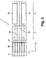
- Fig. 2
- eine Seitenansicht der in Fig. 1 gezeigten Strahlformungsoptik;
- Fig. 3
- eine Seitenansicht eines Strahlformungsmoduls mit zwei Strahlformungsoptiken der Fig. 1; und
- Fig. 4
- eine Darstellung zur Verdeutlichung der verminderten Divergenz eines Laserstrahls beim Durchtritt durch eine Planplatte.
- Fig. 1
- a plan view of an embodiment of the beam shaping optical system according to the invention for a diode laser array;
- Fig. 2
- a side view of the beam-forming optical system shown in Figure 1;
- Fig. 3
- a side view of a beam shaping module with two beam shaping optics of Fig. 1; and
- Fig. 4
- a representation to illustrate the reduced divergence of a laser beam when passing through a plane plate.
Die in Fig. 1 in einer Draufsicht sowie in Fig. 2 in einer Seitenansicht gezeigte Strahlformungsoptik 1 dient zur Zusammenführung (Verkämmung) von sechs Laserstrahlen, die von einer Diodenlaseranordnung 2, welche als horizontaler Stack mit sechs Diodenbarren 30 ausgebildet ist, parallel zueinander in Z-Richtung emittiert werden und von denen vier in Fig. 1 durch ihre Randstrahlen dargestellt sind.The beam-shaping optical system 1 shown in a plan view in FIG. 1 in a plan view and in FIG. 2 serves to bring together (conceal) six laser beams which are parallel to one another in Z.sub.1 of a
Um die weitere Strahlformungsoptik möglichst einfach gestalten zu können, sind die Diodenbarren 30 mit einem geringen vertikalen Versatz angeordnet (sog. "Barren-Pitch"). Dieser Pitch beträgt typischerweise ca. 1,5 mm, was der ca. 1,5- bis 2-fachen Ausdehnung eines Laserstrahls 16, 17 in Y-Richtung (FA-Richtung) entspricht, nachdem dieser einen FA-Kollimator 21 durchlaufen hat, welcher unmittelbar an die Diodenbarren 30 anschließt. Zur Erzeugung dieses Versatzes werden vorzugsweise die Wärmesenken der Diodenbarren 30 leicht keilförmig in X-Richtung (SA-Richtung) ausgeführt, was die Verwendung identischer Wärmesenken für alle Diodenbarren 30 erlaubt. In Strahlrichtung (Z-Richtung) betrachtet ist die Strahlung der Diodenbarren 30 in Form einer flachen Treppe angeordnet. Relativ zur horizontal ausgerichteten SA-Richtung ist eine nicht bildlich dargestellte Kühlplatte des horizontalen Stacks 2 leicht gekippt.In order to make the further beam shaping optics as simple as possible, the diode bars 30 are arranged with a small vertical offset (so-called "bar pitch"). This pitch is typically about 1.5 mm, which corresponds to about 1.5 to 2 times the extent of a
Die Strahlformungsoptik 1 zur Zusammenführung der Laserstrahlung der Diodenbarren 30 weist zwei im Strahlweg hintereinander angeordnete Verkämmungsstufen 3, 4 auf. In der ersten Verkämmungsstufe 4 werden die von jeweils zwei benachbarten Diodenbarren 30 des horizontalen Stacks 2 emittierten Laserstrahlen 16, 17 jeweils mittels zweier Lateralversetzungseinheiten 18, 19, welche durch zwei unter entgegengesetzt gleichen Winkeln zur Strahlrichtung angeordnete Planparallelplatten gebildet sind, paarweise symmetrisch übereinandergelegt. Aufgrund der Symmetrie der Anordnung ist die optische Weglänge für die Laserstrahlen aus den Diodenbarren 30 in der ersten Verkämmungsstufe 4 gleich. Zur Erzeugung des horizontalen Strahlversatzes werden die Planparallelplatten 18, 19 in Transmission durchlaufen. Hierbei bildet die Flächennormale einer Eintrittsfläche 20 der Planparallelplatten mit den Laserstrahlen 16, 17 einen Winkel, der dem Brewster-Winkel αB des Materials der Planparallelplatten 18, 19 entspricht. Durch Nutzung des Brewster-Winkels αB kann, da die Diodenbarren 30 horizontal polarisiert emittieren, auf eine Entspiegelung der Ein- und Austrittsflächen der Planparallelplatten 18, 19 verzichtet werden. Für eine Planparallelplatte 18, 19 werden lediglich zwei optische Flächen, nämlich die Eintrittsfläche 20 und eine Austrittsfläche 23, mit guter Parallelität benötigt. Die Justierempfindlichkeit der Planparallelplatten 18, 19 ist gering. Die Richtung der austretenden Strahlung wird weder durch Verdrehen noch durch Verschieben der Planparallelplatten 18, 19 beeinflußt.The beam-shaping optical system 1 for combining the laser radiation of the diode bars 30 has two
In der zweiten Verkämmungsstufe 3 der Strahlformungsoptik 1 werden die nach der ersten Verkämmungsstufe 4 horizontal versetzt angeordneten, einlaufenden Laserstrahlen 5, 6, 7 vollständig übereinandergelegt, so dass ein auslaufender Laserstrahl 8 als vertikaler optischer Laserstrahlenstapel die Strahlformungsoptik 1 verlässt. Die zweite Verkämmungsstufe 3 weist zwei Lateralversetzungseinheiten 10, 11 in Form von Doppelumlenkprismen auf, die mit senkrecht zur Strahlausbreitungsrichtung angeordneten Ein- und Austrittsflächen und parallelen, schräg angeordneten Seitenflächen 12, 13, 14, 15 zur paarweisen Totalreflexion und damit zur Erzielung eines horizontalen Strahlversatzes positioniert sind. Die vertikale Ausdehnung der Doppelumlenkprismen 10, 11 beträgt das Zweifache des Barren-Pitchs. In der Verkämmungsstufe 3 kann auf eine vollständige Symmetrie verzichtet werden, da die effektiven Weglängen der drei einlaufenden Laserstrahlen 5, 6, 7 nahezu gleich lang sind. Die optische Verkürzung durch Propagation der zwei äußeren Laserstrahlen 5, 7 im höherbrechenden Medium der Doppelumlenkprismen 10, 11 wird hierbei genutzt, um die größere geometrische Weglänge der beiden horizontal versetzten Laserstrahlen 5, 7 gegenüber dem mittleren Laserstrahl 6 zu kompensieren. Im vorliegenden Fall werden nur zwei identische Doppelumlenkprismen 10, 11 für die Zusammenführung der Laserstrahlung des horizontalen Stacks 2 benötigt. Der mittlere Laserstrahl 6 geht, ohne ein optisches Element zu durchlaufen, zwischen den beiden Doppelumlenkprismen 10, 11 hindurch.In the
Bezüglich der mechanischen Fixierung der optischen Elemente der ersten Verkämmungsstufe 4 und der zweiten Verkämmungsstufe 3 bestehen verschiedene Möglichkeiten. Die Planparallelplatten 18, 19 der ersten Verkämmungsstufe 4 können beispielsweise am horizontalen Stack 2 befestigt werden. Hierzu müssen die Kühlplatten und/oder die Wärmesenken des horizontalen Stacks 2 ausreichend weit unter den Planparallelplatten 18, 19 ausgedehnt sein und vorzugweise eine plane, SA-parallele Auflagefläche umfassen, auf die die Planparallelplatten 18, 19 aufgeklebt werden können. Anschließend an die Verkämmung wird der auslaufende Laserstrahl 8 in der FA-Richtung mit Hilfe einer nicht dargestellten Zylinderlinse auf die Eintrittsfläche eines nicht dargestellten Lichtmischers fokussiert und in der SA-Richtung mit Hilfe eines Zylinderlinsenteleskops auf diese Eintrittsfläche abgebildet.With regard to the mechanical fixation of the optical elements of the first meshing stage 4 and the
In Fig. 3 ist eine Seitenansicht eines Strahlformungsmoduls 100 mit zwei der in Fig. 1 gezeigten Strahlformungsoptiken 1 gezeigt, welche identisch aufgebaut und in Y-Richtung zu einer Stapeleinheit 101 übereinander gestapelt sind. Durch diese Aufteilung der benötigten Anzahl der Diodenbarren 30 auf mehrere, vertikal gestapelte horizontale Stacks 2 lässt sich ein sehr kompaktes Format einer Pumplichtquelle für Hochleistungsfestkörperlaser erreichen. Die Doppelumlenkprismen 10, 11 der zweiten Verkämmungsstufe 3 können hierbei beispielsweise mit Hilfe von zusätzlichen - außerhalb des Strahlenganges befindlichen - Abstandshaltern 22 - vorzugsweise aus Glas - zu einem quasimonolithischen Stapel zusammengefügt (z.B. geklebt) werden. FIG. 3 shows a side view of a beam-shaping
In Fig. 4 ist die Verringerung der Divergenz eines Laserstrahls beim Durchtriltt durch eine Planplatte 42 veranschaulicht, welche eine höhere Brechzahl als das umgebende Medium (z.B. Luft) aufweist. Der Laserstrahl weist vor dem Eintritt in die Planplatte 42 einen Durchmesser S1 in X-Richtung auf. Er ist durch zwei Randstrahlen 40, 41 veranschaulicht, welche unter einem Winkel α1 bezüglich des Einfallslots (Z-Richtung) auf eine Eintrittsfläche 43 der Planplatte 42 auftreffen. Beim Durchtritt durch die Eintrittsfläche werden die Randstrahlen 40, 41 zum Einfallslot hin gebrochen, sodass sie im Inneren der Planplatte 42 unter einem Winkel α2 bezüglich des Lots verlaufen. Der Öffnungswinkel des Laserstrahls und somit die Strahldivergenz ist daher innerhalb der Planplatte 42 mit größerer Brechzahl somit geringer als im umgebenden Medium mit geringerer Brechzahl. Beim Durchtritt der Ranstrahlen 40, 41 durch eine Austrittsfläche 44 der Planplatte 42 werden diese so gebrochen, dass sie hinter der Planplatte 42 wieder unter dem Winkel α1 bezüglich der Z-Richtung verlaufen. Die Strahldivergenz vor dem Eintritt des Laserstrahls in die Planplatte 42 und nach dem Austritt des Laserstrahls aus der Planplatte 42 sind somit identisch. Der Durchmesser S2 des Laserstrahls nach dem Austritt aus der Planplatte 42 ist in X-Richtung jedoch um 2Δs geringer als der eines Laserstrahls, der sich ausschließlich im Medium mit der geringeren Brechzahl fortbewegt. Die Randstrahlen 45, 46 eines solchen Laserstrahls sind in Fig. 4 gestrichelt gezeichnet. Durch die Verwendung der Planplatte 42 lässt sich der Durchmesser des Laserstrahls in X-Richtung somit um 2Δs verkürzen. Der axiale Versatz Δz (in Strahlrichtung Z) des durch die Planplatte 42 (mit Länge L in Strahlrichtung Z) verlaufenden Laserstrahls gegenüber einem ohne Durchtritt durch die Planplatte 42 in Luft verlaufenden Strahl lässt sich (bei kleinen Winkeln α1 und α2) annähernd wie folgt berechnen: 
Claims (10)
- Beam-shaping optical unit (1) having at least one combing stage (3) for combining three incoming laser beams (5, 6, 7), which are laterally displaced relative to each other in two directions (X, Y), in order to form an outgoing combed laser beam (8), the combing stage (3) having two lateral displacement units (10, 11) each for laterally displacing one of the two incoming laser beams (5, 7) that are outermost in the first direction (X) in the first direction (X) relative to the central incoming laser beam (6) which travels through the combing stage (3) in a laterally non-displaced manner, and the lateral displacement units (10, 11) each having at least one lateral displacement element having a higher refractive index than the medium which is located in the beam path of the central laser beam (6) in the combing stage (3), the path length travelled by the outermost laser beams (5, 7) in the lateral displacement elements being selected in such a manner that the diameters of the laser beams (5, 6, 7) are approximately identical at least in the first direction (X) at the end of the combing stage (3) and the combed laser beam (8) has substantially identical divergence characteristics over the beam cross-section thereof.
- Beam-shaping optical unit according to claim 1, characterised in that the incoming laser beams (5, 6, 7) and the outgoing laser beam (8) are parallel with each other.
- Beam-shaping optical unit according to claim 1 or 2, characterised in that the central laser beam (6) extends in air.
- Beam-shaping optical unit according to any one of the preceding claims, characterised in that the lateral displacement units (10, 11) each produce the lateral displacement by total reflection at least at two total reflection faces (12, 13, 14, 15).
- Beam-shaping optical unit according to claim 4, characterised in that the lateral displacement units (10, 11) are in the form of double redirection prisms.
- Beam-shaping optical unit according to any one of the preceding claims, characterised in that there is arranged upstream of the combing stage (3) an additional combing stage (4) which combines two incoming laser beams (16, 17), which are laterally displaced relative to each other in the first and second direction (X, Y), in order to form a combed outgoing laser beam (6).
- Beam-shaping optical unit according to claim 6, characterised in that the upstream combing stage (4) comprises two lateral displacement units (18, 19), in particular plane-parallel plates, in order to laterally displace the two incoming laser beams (16, 17) towards each other in the first direction (X).
- Beam-shaping optical unit according to claim 7, characterised in that the incoming laser beam (16, 17) is introduced into an inlet face (20) of the lateral displacement unit (18, 19) at the Brewster angle (αB).
- Beam-shaping module (100) having at least two beam-shaping optical units (1) according to any one of the preceding claims, which are combined in the second direction (Y) in order to form at least one stack unit (101).
- Beam-shaping module according to claim 9, characterised in that the beam-shaping optical units (1) are identical.
Priority Applications (4)
| Application Number | Priority Date | Filing Date | Title |
|---|---|---|---|
| AT04012863T ATE363758T1 (en) | 2004-05-29 | 2004-05-29 | BEAM SHAPING OPTICS AND MODULE FOR A DIODE LASER ARRANGEMENT |
| DE502004003956T DE502004003956D1 (en) | 2004-05-29 | 2004-05-29 | Beamforming optics and module for a diode laser array |
| EP04012863A EP1601072B1 (en) | 2004-05-29 | 2004-05-29 | Beam shaping optics and module for a diode laser assembly |
| US11/138,900 US7167312B2 (en) | 2004-05-29 | 2005-05-27 | Beam shaping optics and module for a diode laser arrangement |
Applications Claiming Priority (1)
| Application Number | Priority Date | Filing Date | Title |
|---|---|---|---|
| EP04012863A EP1601072B1 (en) | 2004-05-29 | 2004-05-29 | Beam shaping optics and module for a diode laser assembly |
Publications (2)
| Publication Number | Publication Date |
|---|---|
| EP1601072A1 EP1601072A1 (en) | 2005-11-30 |
| EP1601072B1 true EP1601072B1 (en) | 2007-05-30 |
Family
ID=34925196
Family Applications (1)
| Application Number | Title | Priority Date | Filing Date |
|---|---|---|---|
| EP04012863A Not-in-force EP1601072B1 (en) | 2004-05-29 | 2004-05-29 | Beam shaping optics and module for a diode laser assembly |
Country Status (4)
| Country | Link |
|---|---|
| US (1) | US7167312B2 (en) |
| EP (1) | EP1601072B1 (en) |
| AT (1) | ATE363758T1 (en) |
| DE (1) | DE502004003956D1 (en) |
Families Citing this family (11)
| Publication number | Priority date | Publication date | Assignee | Title |
|---|---|---|---|---|
| JP4234697B2 (en) * | 2005-06-15 | 2009-03-04 | 浜松ホトニクス株式会社 | Laser equipment |
| US7265906B2 (en) * | 2005-07-12 | 2007-09-04 | The Boeing Company | Tri-to-hex light mixing and homogenizing apparatus and method |
| US7414793B2 (en) | 2006-07-21 | 2008-08-19 | The Boeing Company | White light splitting and homogenizing systems and methods |
| US7443591B1 (en) * | 2007-02-01 | 2008-10-28 | The Boeing Company | Homogenizing optical beam combiner |
| US7386214B1 (en) | 2007-02-01 | 2008-06-10 | The Boeing Company | Homogenizing optical beam combiner |
| US7603017B2 (en) * | 2007-02-01 | 2009-10-13 | The Boeing Company | Multi-color curved multi-light generating apparatus |
| DE102011016253B4 (en) | 2011-04-06 | 2014-02-27 | Laserline Gesellschaft für Entwicklung und Vertrieb von Diodenlasern mbH | diode laser |
| US9690107B2 (en) | 2013-03-15 | 2017-06-27 | Trumpf Laser Gmbh | Device for wavelength combining of laser beams |
| US9851570B2 (en) | 2014-09-18 | 2017-12-26 | Ipg Photonics Corporation | Beam shaping of high intensity high frequency optical output |
| CN208140648U (en) * | 2015-10-14 | 2018-11-23 | 阿尔卑斯电气株式会社 | The measurement device of flow channel structure and measure object liquid |
| US11876343B2 (en) * | 2021-05-18 | 2024-01-16 | Trumpf Photonics, Inc. | Laser diode packaging platforms |
Family Cites Families (13)
| Publication number | Priority date | Publication date | Assignee | Title |
|---|---|---|---|---|
| US6873639B2 (en) * | 1993-05-28 | 2005-03-29 | Tong Zhang | Multipass geometry and constructions for diode-pumped solid-state lasers and fiber lasers, and for optical amplifier and detector |
| US6373868B1 (en) * | 1993-05-28 | 2002-04-16 | Tong Zhang | Single-mode operation and frequency conversions for diode-pumped solid-state lasers |
| DE4438368C3 (en) * | 1994-10-27 | 2003-12-04 | Fraunhofer Ges Forschung | Arrangement for guiding and shaping beams of a straight-line laser diode array |
| DE19514626C2 (en) * | 1995-04-26 | 1997-03-06 | Fraunhofer Ges Forschung | Arrangement for shaping the geometric cross section of a radiation field of one or more solid-state and / or semiconductor lasers |
| US6028722A (en) * | 1996-03-08 | 2000-02-22 | Sdl, Inc. | Optical beam reconfiguring device and optical handling system for device utilization |
| US5761234A (en) * | 1996-07-09 | 1998-06-02 | Sdl, Inc. | High power, reliable optical fiber pumping system with high redundancy for use in lightwave communication systems |
| US5784203A (en) * | 1996-11-26 | 1998-07-21 | Beckmann; Leo H. J. F. | Method and apparatus for combining the radiation output from a linear array of radiation sources |
| US5900981A (en) * | 1997-04-15 | 1999-05-04 | Scitex Corporation Ltd. | Optical system for illuminating a spatial light modulator |
| DE19918444C2 (en) * | 2000-03-15 | 2001-06-21 | Laserline Ges Fuer Entwicklung | Laser optics and diode lasers |
| DE19939750C2 (en) | 1999-08-21 | 2001-08-23 | Laserline Ges Fuer Entwicklung | Optical arrangement for use in a laser diode arrangement and laser diode arrangement with such an optical arrangement |
| US6377410B1 (en) * | 1999-10-01 | 2002-04-23 | Apollo Instruments, Inc. | Optical coupling system for a high-power diode-pumped solid state laser |
| DE10061265A1 (en) | 2000-12-06 | 2002-06-27 | Jenoptik Jena Gmbh | The diode laser assembly |
| DE10204796A1 (en) * | 2002-02-01 | 2003-08-21 | Ozygus Bernd | Laser gain module |
-
2004
- 2004-05-29 AT AT04012863T patent/ATE363758T1/en not_active IP Right Cessation
- 2004-05-29 EP EP04012863A patent/EP1601072B1/en not_active Not-in-force
- 2004-05-29 DE DE502004003956T patent/DE502004003956D1/en active Active
-
2005
- 2005-05-27 US US11/138,900 patent/US7167312B2/en active Active
Also Published As
| Publication number | Publication date |
|---|---|
| US7167312B2 (en) | 2007-01-23 |
| US20050270652A1 (en) | 2005-12-08 |
| ATE363758T1 (en) | 2007-06-15 |
| EP1601072A1 (en) | 2005-11-30 |
| DE502004003956D1 (en) | 2007-07-12 |
Similar Documents
| Publication | Publication Date | Title |
|---|---|---|
| DE19537265C1 (en) | Combining and shaping device for multiple laser diode rows esp. for coupling into optical fibre or solid state laser rod | |
| DE112013007759B3 (en) | Semiconductor laser device | |
| DE19743322B4 (en) | Laser beam shaping system | |
| EP0863588B1 (en) | Laseroptics and laserdiode | |
| EP0803075B1 (en) | Optical arrangement for use in a laser diode system | |
| DE10220378B4 (en) | Laser light source device with optical elements for beam correction | |
| DE112011100813T5 (en) | SYSTEM AND METHOD FOR SELECTIVE REPOSITIONING AND SWIVEL LENGTH COMBINATION | |
| EP0934545A1 (en) | Optical array for symmetrization of laser diode beams | |
| DE102004002221B3 (en) | Optical symmetry device for high power laser diode array used in materials processing, medical, telecommunications, illumination, display, analysis, printing or photographic device, or for laser pumping | |
| WO2009068192A1 (en) | Beam forming device | |
| DE19751716C2 (en) | Arrangement for shaping and guiding radiation | |
| EP1145390A2 (en) | Laser amplification system | |
| EP2219064A1 (en) | Laser lens and diode laser | |
| EP1601072B1 (en) | Beam shaping optics and module for a diode laser assembly | |
| DE19544488A1 (en) | Optical arrangement for use in a laser diode arrangement | |
| EP2240984B1 (en) | Diode laser array for creating diode laser output with optimised beam parameter products for fibre coupling | |
| DE112019003882B4 (en) | LASER SYSTEM WITH SLOW-AXIS COLLIMATORS ARRANGED IN A STAIRWAY | |
| DE19752416A1 (en) | Method and device for combining the radiation power of a linear arrangement of radiation sources | |
| EP2508934B1 (en) | Diode Laser | |
| EP2309309A2 (en) | Device for shaping laser radiation | |
| DE112020000301T5 (en) | SYSTEMS AND METHODS FOR ALIGNING WAVELENGTH BEAM COMBINING RESONATORS | |
| EP1384105B1 (en) | Beam shaping device for shaping the cross-section of a light beam | |
| EP0903823B1 (en) | Laser element incorporating a laser array and method of fabrication | |
| DE10012480C2 (en) | Laser optics and diode lasers | |
| WO2011085794A1 (en) | Optical assembly for optically pumping an active medium |
Legal Events
| Date | Code | Title | Description |
|---|---|---|---|
| PUAI | Public reference made under article 153(3) epc to a published international application that has entered the european phase |
Free format text: ORIGINAL CODE: 0009012 |
|
| 17P | Request for examination filed |
Effective date: 20050429 |
|
| AK | Designated contracting states |
Kind code of ref document: A1 Designated state(s): AT BE BG CH CY CZ DE DK EE ES FI FR GB GR HU IE IT LI LU MC NL PL PT RO SE SI SK TR |
|
| AX | Request for extension of the european patent |
Extension state: AL HR LT LV MK |
|
| GRAP | Despatch of communication of intention to grant a patent |
Free format text: ORIGINAL CODE: EPIDOSNIGR1 |
|
| GRAS | Grant fee paid |
Free format text: ORIGINAL CODE: EPIDOSNIGR3 |
|
| AKX | Designation fees paid |
Designated state(s): AT CH DE FR GB IT LI |
|
| GRAA | (expected) grant |
Free format text: ORIGINAL CODE: 0009210 |
|
| AK | Designated contracting states |
Kind code of ref document: B1 Designated state(s): AT CH DE FR GB IT LI |
|
| REG | Reference to a national code |
Ref country code: GB Ref legal event code: FG4D Free format text: NOT ENGLISH |
|
| REG | Reference to a national code |
Ref country code: CH Ref legal event code: EP |
|
| REF | Corresponds to: |
Ref document number: 502004003956 Country of ref document: DE Date of ref document: 20070712 Kind code of ref document: P |
|
| ET | Fr: translation filed | ||
| GBT | Gb: translation of ep patent filed (gb section 77(6)(a)/1977) |
Effective date: 20070829 |
|
| PLBE | No opposition filed within time limit |
Free format text: ORIGINAL CODE: 0009261 |
|
| STAA | Information on the status of an ep patent application or granted ep patent |
Free format text: STATUS: NO OPPOSITION FILED WITHIN TIME LIMIT |
|
| 26N | No opposition filed |
Effective date: 20080303 |
|
| PGFP | Annual fee paid to national office [announced via postgrant information from national office to epo] |
Ref country code: CH Payment date: 20080409 Year of fee payment: 5 |
|
| PGFP | Annual fee paid to national office [announced via postgrant information from national office to epo] |
Ref country code: AT Payment date: 20080404 Year of fee payment: 5 |
|
| PGFP | Annual fee paid to national office [announced via postgrant information from national office to epo] |
Ref country code: FR Payment date: 20080404 Year of fee payment: 5 |
|
| REG | Reference to a national code |
Ref country code: CH Ref legal event code: PL |
|
| PG25 | Lapsed in a contracting state [announced via postgrant information from national office to epo] |
Ref country code: CH Free format text: LAPSE BECAUSE OF NON-PAYMENT OF DUE FEES Effective date: 20090531 Ref country code: AT Free format text: LAPSE BECAUSE OF NON-PAYMENT OF DUE FEES Effective date: 20090529 Ref country code: LI Free format text: LAPSE BECAUSE OF NON-PAYMENT OF DUE FEES Effective date: 20090531 |
|
| REG | Reference to a national code |
Ref country code: FR Ref legal event code: ST Effective date: 20100129 |
|
| PG25 | Lapsed in a contracting state [announced via postgrant information from national office to epo] |
Ref country code: FR Free format text: LAPSE BECAUSE OF NON-PAYMENT OF DUE FEES Effective date: 20090602 |
|
| PGFP | Annual fee paid to national office [announced via postgrant information from national office to epo] |
Ref country code: DE Payment date: 20210520 Year of fee payment: 18 Ref country code: IT Payment date: 20210527 Year of fee payment: 18 |
|
| PGFP | Annual fee paid to national office [announced via postgrant information from national office to epo] |
Ref country code: GB Payment date: 20210520 Year of fee payment: 18 |
|
| REG | Reference to a national code |
Ref country code: DE Ref legal event code: R119 Ref document number: 502004003956 Country of ref document: DE |
|
| GBPC | Gb: european patent ceased through non-payment of renewal fee |
Effective date: 20220529 |
|
| PG25 | Lapsed in a contracting state [announced via postgrant information from national office to epo] |
Ref country code: GB Free format text: LAPSE BECAUSE OF NON-PAYMENT OF DUE FEES Effective date: 20220529 Ref country code: DE Free format text: LAPSE BECAUSE OF NON-PAYMENT OF DUE FEES Effective date: 20221201 |
|
| PG25 | Lapsed in a contracting state [announced via postgrant information from national office to epo] |
Ref country code: IT Free format text: LAPSE BECAUSE OF NON-PAYMENT OF DUE FEES Effective date: 20220529 |