EP1601051A2 - Multiaxial loop antenna chip - Google Patents
Multiaxial loop antenna chip Download PDFInfo
- Publication number
- EP1601051A2 EP1601051A2 EP05018694A EP05018694A EP1601051A2 EP 1601051 A2 EP1601051 A2 EP 1601051A2 EP 05018694 A EP05018694 A EP 05018694A EP 05018694 A EP05018694 A EP 05018694A EP 1601051 A2 EP1601051 A2 EP 1601051A2
- Authority
- EP
- European Patent Office
- Prior art keywords
- axis
- antenna chip
- core
- coil portion
- casing
- Prior art date
- Legal status (The legal status is an assumption and is not a legal conclusion. Google has not performed a legal analysis and makes no representation as to the accuracy of the status listed.)
- Granted
Links
Images





Classifications
-
- H—ELECTRICITY
- H01—ELECTRIC ELEMENTS
- H01Q—ANTENNAS, i.e. RADIO AERIALS
- H01Q21/00—Antenna arrays or systems
- H01Q21/28—Combinations of substantially independent non-interacting antenna units or systems
-
- G—PHYSICS
- G07—CHECKING-DEVICES
- G07C—TIME OR ATTENDANCE REGISTERS; REGISTERING OR INDICATING THE WORKING OF MACHINES; GENERATING RANDOM NUMBERS; VOTING OR LOTTERY APPARATUS; ARRANGEMENTS, SYSTEMS OR APPARATUS FOR CHECKING NOT PROVIDED FOR ELSEWHERE
- G07C9/00—Individual registration on entry or exit
- G07C9/00174—Electronically operated locks; Circuits therefor; Nonmechanical keys therefor, e.g. passive or active electrical keys or other data carriers without mechanical keys
- G07C9/00309—Electronically operated locks; Circuits therefor; Nonmechanical keys therefor, e.g. passive or active electrical keys or other data carriers without mechanical keys operated with bidirectional data transmission between data carrier and locks
-
- G—PHYSICS
- G07—CHECKING-DEVICES
- G07C—TIME OR ATTENDANCE REGISTERS; REGISTERING OR INDICATING THE WORKING OF MACHINES; GENERATING RANDOM NUMBERS; VOTING OR LOTTERY APPARATUS; ARRANGEMENTS, SYSTEMS OR APPARATUS FOR CHECKING NOT PROVIDED FOR ELSEWHERE
- G07C9/00—Individual registration on entry or exit
- G07C9/00174—Electronically operated locks; Circuits therefor; Nonmechanical keys therefor, e.g. passive or active electrical keys or other data carriers without mechanical keys
- G07C9/00944—Details of construction or manufacture
-
- H—ELECTRICITY
- H01—ELECTRIC ELEMENTS
- H01Q—ANTENNAS, i.e. RADIO AERIALS
- H01Q1/00—Details of, or arrangements associated with, antennas
- H01Q1/27—Adaptation for use in or on movable bodies
- H01Q1/32—Adaptation for use in or on road or rail vehicles
- H01Q1/3208—Adaptation for use in or on road or rail vehicles characterised by the application wherein the antenna is used
-
- H—ELECTRICITY
- H01—ELECTRIC ELEMENTS
- H01Q—ANTENNAS, i.e. RADIO AERIALS
- H01Q1/00—Details of, or arrangements associated with, antennas
- H01Q1/27—Adaptation for use in or on movable bodies
- H01Q1/32—Adaptation for use in or on road or rail vehicles
- H01Q1/3208—Adaptation for use in or on road or rail vehicles characterised by the application wherein the antenna is used
- H01Q1/3233—Adaptation for use in or on road or rail vehicles characterised by the application wherein the antenna is used particular used as part of a sensor or in a security system, e.g. for automotive radar, navigation systems
- H01Q1/3241—Adaptation for use in or on road or rail vehicles characterised by the application wherein the antenna is used particular used as part of a sensor or in a security system, e.g. for automotive radar, navigation systems particular used in keyless entry systems
-
- H—ELECTRICITY
- H01—ELECTRIC ELEMENTS
- H01Q—ANTENNAS, i.e. RADIO AERIALS
- H01Q21/00—Antenna arrays or systems
- H01Q21/24—Combinations of antenna units polarised in different directions for transmitting or receiving circularly and elliptically polarised waves or waves linearly polarised in any direction
-
- H—ELECTRICITY
- H01—ELECTRIC ELEMENTS
- H01Q—ANTENNAS, i.e. RADIO AERIALS
- H01Q7/00—Loop antennas with a substantially uniform current distribution around the loop and having a directional radiation pattern in a plane perpendicular to the plane of the loop
-
- H—ELECTRICITY
- H01—ELECTRIC ELEMENTS
- H01Q—ANTENNAS, i.e. RADIO AERIALS
- H01Q7/00—Loop antennas with a substantially uniform current distribution around the loop and having a directional radiation pattern in a plane perpendicular to the plane of the loop
- H01Q7/06—Loop antennas with a substantially uniform current distribution around the loop and having a directional radiation pattern in a plane perpendicular to the plane of the loop with core of ferromagnetic material
-
- H—ELECTRICITY
- H01—ELECTRIC ELEMENTS
- H01Q—ANTENNAS, i.e. RADIO AERIALS
- H01Q7/00—Loop antennas with a substantially uniform current distribution around the loop and having a directional radiation pattern in a plane perpendicular to the plane of the loop
- H01Q7/06—Loop antennas with a substantially uniform current distribution around the loop and having a directional radiation pattern in a plane perpendicular to the plane of the loop with core of ferromagnetic material
- H01Q7/08—Ferrite rod or like elongated core
-
- E—FIXED CONSTRUCTIONS
- E05—LOCKS; KEYS; WINDOW OR DOOR FITTINGS; SAFES
- E05B—LOCKS; ACCESSORIES THEREFOR; HANDCUFFS
- E05B19/00—Keys; Accessories therefor
- E05B19/0082—Keys or shanks being removably stored in a larger object, e.g. a remote control or a key fob
Definitions
- the present invention relates to a multiaxial antenna chip mounted on a circuit board or the like.
- the remote control apparatus comprises a portable transmitter-receiver 101 that communicates with a transmission and reception device provided in a vehicle.
- the portable transmitter-receiver 101 is carried by a user of the vehicle.
- one-axis antenna 102 is mounted in the portable transmitter-receiver 101 to transmit and receive an electric wave to and from the transmission and reception device.
- the current portable transmitter-receiver 101 Since the current portable transmitter-receiver 101 is massive, it has been desirable to further reduce its size. However, when an attempt is made to miniaturize the portable transmitter-receiver 101, it is difficult to reduce the sizes of parts such as a mechanical key 103. Thus, it is contemplated that electric parts such as the one-axis antenna 102 are miniaturized.
- the portable transmitter-receiver 101 contains a plurality of (in FIG. 22, two) one-axis antennas 102 in order to receive reliably electric waves from many directions. These one-axis antennas 102 are arranged in different orientations. As a result, the portable transmitter-receiver 101 must contain a mounting space for the two one-axis antennas 102. This contributes to increasing the size of the entire portable transmitter-receiver 101.
- the one-axis antennas 102 are separately mounted on a circuit board 104. Accordingly, the one-axis antennas 102 may be misaligned with respect to each other. This reduces the directionality of the antennas.
- the present invention provides a multiaxial antenna chip including a core and coil portions.
- the core includes at least two arm portions. Each arm portion extends in a direction different from the other arm portion and has a coil portion provided about it.
- a vehicle remote control apparatus 11 comprises a transmission and reception device 13 provided in the vehicle and a portable transmitter-receiver 12 carried by a user.
- the transmission and reception device 13 comprises a transmission circuit 31, reception circuits 32 and 33, a microcomputer 34, and a switching circuit 35.
- the transmission circuit 31 and the reception circuits 32 and 33 are connected to the microcomputer 34.
- a transmission and reception antenna 36 is connected to the transmission circuit 31 and reception circuit 33 via the switching circuit 35.
- the switching circuit 35 allows the transmission and reception antenna 36 to be selectively connected to the transmission circuit 31 or the reception circuit 33. Further, a reception antenna 32a is connected to the reception circuit 32.
- the transmission circuit 31 converts a request signal outputted by the microcomputer 34 into an electric wave of a predetermined frequency, and then outputs the electric wave via the transmission and reception antenna 36. Further, the transmission circuit 31 converts a transponder driving signal outputted by the microcomputer 34 into an electric wave of a predetermined frequency. The transmission circuit 31 thus generates a transponder driving current, and then outputs the current via the transmission and reception antenna 36. Specifically, both a request signal and a transponder driving current are outputted through the transmission and reception antenna 36. That is, the same antenna is used to output the request signal and the transponder driving current.
- the reception circuit 32 can receive an ID code signal from the portable transmitter-receiver 12 via the reception antenna 32a.
- the reception circuit 32 demodulates its ID code signal into a pulse signal to generate a receive signal and then outputs the receive signal to the microcomputer 34.
- the reception circuit 33 can receive a transponder signal from the portable transmitter-receiver 12 via the transmission and reception antenna 36.
- the transmission and reception antenna 36 is connected to the reception circuit 33 by the switching circuit 35.
- the reception circuit 33 demodulates its transponder signal into a pulse signal to generate a receive signal and then outputs the receive signal to the microcomputer 34.
- An engine starter 17 is electrically connected to the microcomputer 34.
- the microcomputer 34 is composed of a CPU, a RAM, a ROM, and the like, which are not shown in the drawings.
- the microcomputer 34 selectively outputs the request signal and the transponder signal.
- the microcomputer 34 When a receive signal containing an ID code is inputted to the microcomputer 34, the latter compares a preset ID code with the ID code contained in the receive signal (collates the ID codes). If the ID codes match each other, the microcomputer 34 outputs a start permission signal to the engine starter 17.
- the microcomputer 34 compares a preset transponder code with the transponder code contained in the receive signal (collates the transponder codes). If the transponder codes match each other, the microcomputer 34 outputs a start permission signal to the engine starter 17. An engine is started by rotating an operation knob, not shown in the drawings, while this signal is being outputted.
- the portable transmitter-receiver 12 comprises a reception circuit 20, a microcomputer 21, a transmission circuit 23, and a transponder 22.
- the reception circuit receives a request signal from the transmission and reception device 13 via a three-axis antenna chip 70 as a multiaxial antenna chip and inputs this signal to the microcomputer 21.
- the reception circuit 20 inputs a request signal to the microcomputer 21, the latter outputs an ID code signal containing a predetermined ID code.
- the transmission circuit 23 modulates the ID code signal into an electric wave of a predetermined frequency and transmits this electric wave to the transmission and reception device 13 via the three-axis antenna chip 70.
- the transponder 22 comprises a transponder control section 24.
- the transponder control section 24 Upon receiving sufficient energy from an electromagnetic wave, the transponder control section 24 outputs a transponder signal containing an ID code (transponder code) for a predetermined transponder.
- the transponder control section 24 Upon receiving a transponder driving electric wave from the transmission and reception device 13, the transponder control section 24 outputs a transponder signal.
- the portable transmitter-receiver 12 has a generally parallelepiped body formed by a case 28 made of a synthetic resin.
- the case 28 is partitioned into a battery housing section 28b, a mechanical key housing section 28c, and a circuit arranging section 28a.
- a battery 26 is accommodated in the battery housing section 28b.
- a mechanical key 27 is removably accommodated in the mechanical key housing section 28c.
- the reception circuit 20, the microcomputer 21, the transmission circuit 23, the transponder 22, and the three-axis antenna chip 70 are mounted on a circuit board 29 provided in the circuit arranging section 28a.
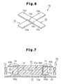
- the three-axis antenna chip 70 comprises a casing 81 made of a synthetic resin.
- the casing 81 has an opening, to which a transparent film 84 consisting of an insulator is stuck.
- the film 84 and the casing 81 are shaped generally like a cross.
- the casing 81 comprises a generally cross-shaped main body 82a having an accommodating concave portion 85 and caps 82b that close respective openings formed at the four corresponding ends of the main body 82a.
- the main body 82a is provided with a generally cross-shaped accommodating concave portion 85.
- Two metal contacts 83 are provided at the respective ends of each cap 82b. Specifically, eight contacts 83 are provided in the three-axis antenna chip 70. As shown in FIG. 7, each contact 83 is insert-molded in the corresponding cap 82b.
- the contact 83 has a mounting portion 83a projected from the cap 82b toward the circuit board 29 and having a generally L-shaped cross section and a connection portion 83b connected to an end of the mounting portion 83a and projected from the opposite sides of the cap 82b.
- the three-axis antenna chip 70 is fixed by soldering the mounting portion 83a to the circuit board 29.
- a core 71 consisting of a magnetic substance is accommodated in the casing 81.
- the core 71 is arranged so as not to interfere with each contact 83.
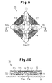
- the core 71 is constructed by forming a plurality of (in the present embodiment, four) bar-like arm portions 72a so that they extend in different directions.
- the core 71 is generally cross-shaped by laying two band-like core pieces 72 on top of each other at their central portions.
- the core pieces 72 cross each other at right angles, and each arm portion 72a extends outward from the crossing portion of the two core pieces 72, or from the center of the core 71.
- One of the core pieces 72 is an X-axis core piece 72 that has a pair of X-axis arm portions 72a.
- the other core piece 72 is a Y-axis core piece 72 that has a pair of Y-axis arm portions 72a.
- a concave portion 72b is formed in the crossing portion of each of the two core pieces 72 by bending the core piece 72 in its thickness direction.
- an inner side 72c of the concave portion 72b in one of the core pieces 72 contacts with the other core piece 72.
- each core piece 72 are each constructed by stacking a plurality of (in the present embodiment, 30) core sheets.
- each core sheet has a board thickness of 15 to 20 ⁇ m.
- each core sheet is formed of a flexible material.
- each core sheet is amorphous and is formed of an alloy consisting of Co and Ni.
- a coil portion 73 is formed around the arm portions 72a and the casing 81.
- the coil portion 73 is composed of a pair of X-axis coil portions 73a, a pair of Y-axis coil portions 73b, and a Z-axis coil portion 73c.
- the X-axis coil portions 73a and the Y-axis coil portions 73b are each constructed by winding an electric wire 74 around the corresponding arm portion 72a.
- the direction of magnetic fluxes generated in the X-axis coil portions 73a is orthogonal to the direction of magnetic fluxes generated in the Y-axis coil portions 73b.
- the X-axis coil portions 73a and the Y-axis coil portions 73b are formed substantially in the same plane in the thickness direction of the casing 81.
- the outer surfaces of the X-axis coil portions 73a and Y-axis coil portions 73b are almost flat in order to allow the core 71 to be properly installed.
- the X-axis coil portions 73a and the Y-axis coil portions 73b are connected together by the electric wires 74 at the crossing portion of the two core pieces 72.
- each winding concave portion 86 is caught in a winding concave portion 86 formed in the tip surface of each cap 82b.
- the Z-axis coil portion 73c is constructed by winding the electric wire 74 along the shortest line passing around the caps 82b of the casing 81.
- the inner surface of each winding concave portion 86 is shaped generally like a circular arc as viewed from the direction shown in FIG. 3.
- the direction of magnetic fluxes generated in the Z-axis coil portion 73c is orthogonal to the direction of magnetic fluxes generated in the X-axis coil portions 73a and Y-axis coil portions 73b. Further, ends of the electric wires 74 extended from the X-axis coil portions 73a, Y-axis coil portions 73b, and Z-axis coil portion 73c are connected to the connection portions 83b of the contacts 83. Some of the contacts 83 are not connected to the electric wire 74 but are used only to fix the three-axis antenna chip 70.
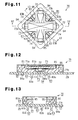
- the three-axis antenna chip 70 may be fixed to the circuit board 29, not only by soldering the contacts 83 to the circuit board 29, but also by engaging the claw portions 94 with the circuit board 29. This further improves the fixation strength of the three-axis antenna chip 70.
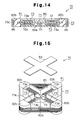
- the core pieces 72 may be formed by sintering.
- FIGS. 14 to 16 show an example of the three-axis antenna chip 70 including the core pieces 72 formed by sintering.
- the core 71 may be integral. If the core 71 is formed of an amorphous alloy, it is formed by stacking a plurality of generally cross-shaped core sheets. Alternatively, if the core 71 is formed of ferrite, it is formed by press molding. With this arrangement, the directions of the arm portions 72a are set beforehand, so that the arm portions 72a can be reliably positioned. This ensures that the three-axis antenna chip 70 can be mounted. It is also possible to prevent the three-axis antenna chip 70 from becoming thicker.
- the core 71 may be generally T-shaped by laying the two core pieces on top of each other.
- the core 71 may be integrally formed so as to be generally T-shaped.
- the concave portion 72b may be formed by bending the crossing portion of only one of the core pieces 72 in their thickness direction.
- the contacts 83 are provided at the respective sides of the corresponding cap 82b. However, each contact 83 may be provided at the corresponding tip edge of the cap 82b. In this case, the contacts 83 are provided at totally four positions in the three-axis antenna chip 70.
- each contact 83 may be provided in the area surrounded by the adjacent arm portions 72a and the Z-axis coil portion 73c (the area corresponding to the space A1 in the above embodiments).
- This arrangement serves to reduce the size of the three-axis antenna chip 70 compared to the case in which each contact 83 is provided at the corresponding tip edge of the cap 82b (as shown in FIG. 18).
- the mounting portion 83a is set be longer than that in the above embodiments, it does not interfere with the coil portion 73. This makes it possible to increase the contact area between the three-axis antenna chip 70 and the circuit board 29. Therefore, the three-axis antenna chip 70 can be mounted more easily.
- the Z-axis coil portion 73c may be arranged on the side of the core 71 which is closer to the circuit board 29.
- the Z-axis coil portion 73c may be arranged on both the side of the core 71 that is closer to the circuit board 29 and on its opposite side. This arrangement allows the Z-axis coil portion 73c to be doubled to increase the sensitivity of the three-axis antenna chip 70 in the Z axis direction.
- the electric wire 74 forming the Z-axis coil portion 73c need not be wound along lines that are parallel to the shortest line passing around the tips of the core pieces 72. That is, for example, as shown in FIG. 21, the corner portions of the Z-axis coil portion 73c need not coincide with the corresponding tip edges of the core pieces 72 in the thickness direction of the three-axis antenna chip 70.
- the core pieces 72 may not be accommodated in the casing 81 but may be mounted directly on the circuit board 29.
Landscapes
- Engineering & Computer Science (AREA)
- Physics & Mathematics (AREA)
- General Physics & Mathematics (AREA)
- Computer Networks & Wireless Communication (AREA)
- Manufacturing & Machinery (AREA)
- Computer Security & Cryptography (AREA)
- Radar, Positioning & Navigation (AREA)
- Remote Sensing (AREA)
- Support Of Aerials (AREA)
- Variable-Direction Aerials And Aerial Arrays (AREA)
- Details Of Aerials (AREA)
Abstract
Description
Claims (10)
- A multiaxial antenna chip, comprising:a generally cross-shaped core (71), which includes an X-axis arm portion (72a) and an Y-axis arm portion (72a) extending perpendicular to each other;an X-axis coil portion (73a) provided about the X-axis arm portion (72a); andan Y-axis coil portion (73b) provided about the Y-axis arm portion (72a), the multiaxial antenna being characterized by:a casing (81) defining an accommodating concave portion (85), wherein the accommodating concave portion (85) has a shape corresponding to that of the core (71), wherein the accommodating concave portion (85) accommodates the core (71) equipped with the coil portions (73a, 73b) such that the core (71) is positioned in the accommodating concave portion (85), wherein the casing (81) is shaped generally like a square, and wherein the core (71) is accommodated in the accommodating concave portion (85) so that the X-axis arm portion (72a) and the Y-axis arm portion (72a) extend along the diagonal lines of the casing (81).
- The multiaxial antenna chip according to claim 1, characterized by a Z-axis coil portion (73c) provided about a Z-axis that extends perpendicular to the X-axis arm portion (72a) and the Y-axis arm portion (72a).
- The multiaxial antenna chip according to claim 2, characterized in that the Z-axis coil portion (73c) is accommodated in the accommodating concave portion (85).
- The multiaxial antenna chip according to claim 3, characterized in that the Z-axis coil portion (73c) is displaced from the core (71) in relation to a direction of the Z-axis.
- The multiaxial antenna chip according to claim 2, characterized in that the Z-axis coil portion (73c) is wound about the casing (81).
- The multiaxial antenna chip according to claim 5, characterized in that the casing (81) has a winding concave portion (86) at its periphery for receiving the Z-axis coil portion (73c).
- The multiaxial antenna chip according to any one of claims 1 to 6, characterized by a plurality of contacts (83), which are insert-molded in the casing (81) or are pressed in a through-hole (81b) formed in the casing (81), each contact (83) being connected to one of the coil portions (73a, 73b), wherein the contacts (83) extend through, and are fixed to, a circuit board (29) on which the multiaxial antenna chip is mounted.
- The multiaxial antenna chip according to any one of claims 1 to 7, characterized by a claw portion (94), wherein the claw portion (94) extends through, and is engaged with, a circuit board (29) on which the multiaxial antenna chip is mounted.
- The multiaxial antenna chip according to any one of claims 1 to 8, characterized in that the casing (81) is made of a synthetic resin.
- The multiaxial antenna chip according to any one of claims 1 to 9, characterized in that the accommodating concave portion (85) has an opening, the opening being covered with a cover (84, 81a).
Applications Claiming Priority (5)
| Application Number | Priority Date | Filing Date | Title |
|---|---|---|---|
| JP2002187995 | 2002-06-27 | ||
| JP2002187995 | 2002-06-27 | ||
| JP2002233586 | 2002-08-09 | ||
| JP2002233586A JP3924512B2 (en) | 2002-06-27 | 2002-08-09 | Chip multi-axis antenna |
| EP20030013498 EP1376762B1 (en) | 2002-06-27 | 2003-06-26 | Multiaxial loop antenna chip |
Related Parent Applications (1)
| Application Number | Title | Priority Date | Filing Date |
|---|---|---|---|
| EP20030013498 Division EP1376762B1 (en) | 2002-06-27 | 2003-06-26 | Multiaxial loop antenna chip |
Publications (3)
| Publication Number | Publication Date |
|---|---|
| EP1601051A2 true EP1601051A2 (en) | 2005-11-30 |
| EP1601051A3 EP1601051A3 (en) | 2005-12-07 |
| EP1601051B1 EP1601051B1 (en) | 2007-04-04 |
Family
ID=29718451
Family Applications (2)
| Application Number | Title | Priority Date | Filing Date |
|---|---|---|---|
| EP20050018694 Expired - Lifetime EP1601051B1 (en) | 2002-06-27 | 2003-06-26 | Multiaxial loop antenna chip |
| EP20030013498 Expired - Lifetime EP1376762B1 (en) | 2002-06-27 | 2003-06-26 | Multiaxial loop antenna chip |
Family Applications After (1)
| Application Number | Title | Priority Date | Filing Date |
|---|---|---|---|
| EP20030013498 Expired - Lifetime EP1376762B1 (en) | 2002-06-27 | 2003-06-26 | Multiaxial loop antenna chip |
Country Status (4)
| Country | Link |
|---|---|
| US (1) | US7068223B2 (en) |
| EP (2) | EP1601051B1 (en) |
| JP (1) | JP3924512B2 (en) |
| DE (2) | DE60313044T2 (en) |
Cited By (4)
| Publication number | Priority date | Publication date | Assignee | Title |
|---|---|---|---|---|
| EP1887587A1 (en) * | 2006-08-12 | 2008-02-13 | Kaschke KG GmbH & Co. | Coil arrangement |
| WO2010013992A1 (en) * | 2008-07-31 | 2010-02-04 | Eng Siang Koh | Flexible thin ribbon helical coil |
| DE102013113244A1 (en) * | 2013-11-29 | 2015-06-03 | Paul Vahle Gmbh & Co. Kg | Coil for an inductive energy transfer system |
| US20190394584A1 (en) * | 2018-06-08 | 2019-12-26 | Sivantos Pte. Ltd. | Antenna And Device With Such An Antenna |
Families Citing this family (52)
| Publication number | Priority date | Publication date | Assignee | Title |
|---|---|---|---|---|
| US20060152427A1 (en) * | 2002-03-05 | 2006-07-13 | Hozumi Ueda | Antenna coil |
| JP3829761B2 (en) | 2002-06-04 | 2006-10-04 | 株式会社デンソー | Receiving antenna, portable device |
| JP3924512B2 (en) | 2002-06-27 | 2007-06-06 | 株式会社東海理化電機製作所 | Chip multi-axis antenna |
| US7023395B2 (en) * | 2003-08-05 | 2006-04-04 | Matsushita Electric Industrial Co., Ltd. | Antenna and communication system using the same |
| JP4483236B2 (en) * | 2003-09-01 | 2010-06-16 | オムロン株式会社 | Wireless terminal position detecting device and wireless terminal position detecting method |
| JP2005124013A (en) * | 2003-10-20 | 2005-05-12 | Toko Inc | 3-axis antenna coil |
| FR2867217B1 (en) * | 2004-03-03 | 2006-05-19 | Valeo Securite Habitacle | KEY COMPRISING A HOUSING FOR PERMANENTLY CLOSED TRANSPONDER |
| DE102005011042A1 (en) * | 2004-03-11 | 2005-09-29 | Marquardt Gmbh | Inductive component, in particular for an electronic key |
| DE602005022838D1 (en) * | 2004-03-12 | 2010-09-23 | Sumida Corp | THREE AXIS ANTENNA AND RECEIVING DEVICE |
| US7317426B2 (en) * | 2005-02-04 | 2008-01-08 | Sensormatic Electronics Corporation | Core antenna for EAS and RFID applications |
| FR2884358B1 (en) | 2005-04-06 | 2009-07-31 | Valeo Securite Habitacle Sas | RADIOFREQUENCY ANTENNA DEVICE WITH ORTHOGONAL BUCKLES |
| JP4548205B2 (en) * | 2005-04-27 | 2010-09-22 | 株式会社デンソー | Wireless transceiver and manufacturing method thereof |
| JP4486016B2 (en) * | 2005-09-21 | 2010-06-23 | 株式会社東海理化電機製作所 | Communication terminal |
| FR2891091B1 (en) | 2005-09-22 | 2008-01-11 | Commissariat Energie Atomique | OMNIDIRECTIONAL PLANAR ANTENNA AND METHOD OF MANUFACTURE |
| US20070115192A1 (en) * | 2005-11-18 | 2007-05-24 | Omron Automotive Electronics, Inc. | Key fob having LF single dimension tranceive antenna and two-dimension receive antenna |
| JP4519188B2 (en) * | 2006-04-07 | 2010-08-04 | スミダコーポレーション株式会社 | Antenna coil |
| CN101401259B (en) * | 2006-04-10 | 2012-06-13 | 胜美达集团株式会社 | Coil part |
| JP3957000B1 (en) * | 2006-07-07 | 2007-08-08 | 株式会社村田製作所 | Antenna coil for board mounting and antenna device |
| JP4724623B2 (en) * | 2006-08-29 | 2011-07-13 | スミダコーポレーション株式会社 | Antenna coil |
| JP4806373B2 (en) * | 2007-05-09 | 2011-11-02 | 富士通株式会社 | Tag device and RFID system using the same |
| EP2026406A1 (en) * | 2007-08-14 | 2009-02-18 | Oticon A/S | Multipurpose antenna unit |
| JP4952439B2 (en) * | 2007-08-22 | 2012-06-13 | パナソニック株式会社 | ANTENNA DEVICE AND WIRELESS COMMUNICATION SYSTEM |
| GB0724697D0 (en) * | 2007-12-19 | 2008-01-30 | Rhodes Mark | Antenna formed of multiple loops |
| GB0724703D0 (en) * | 2007-12-19 | 2008-01-30 | Rhodes Mark | Co-located transmit-receive antenna system |
| DE202008004315U1 (en) * | 2008-03-29 | 2009-08-06 | Neosid Pemetzrieder Gmbh & Co. Kg | Inductive component, in particular antenna |
| US8077105B2 (en) * | 2008-04-04 | 2011-12-13 | Toko Inc. | Directive bar-type antenna |
| JP2009296107A (en) * | 2008-06-03 | 2009-12-17 | Sumida Corporation | Receiving antenna coil |
| JP2010010730A (en) * | 2008-06-24 | 2010-01-14 | Hitachi Ferrite Electronics Ltd | Low-frequency three-axis reception antenna |
| US8461719B2 (en) * | 2008-09-27 | 2013-06-11 | Witricity Corporation | Wireless energy transfer systems |
| JP5375158B2 (en) * | 2009-02-16 | 2013-12-25 | 株式会社デンソー | Transceiver and electronic key having the transceiver |
| JP5161901B2 (en) * | 2010-02-15 | 2013-03-13 | スミダコーポレーション株式会社 | Antenna coil |
| US9057754B2 (en) * | 2010-03-04 | 2015-06-16 | SeeScan, Inc. | Economical magnetic locator apparatus and method |
| JP5660132B2 (en) * | 2010-04-13 | 2015-01-28 | 日立金属株式会社 | Triaxial antenna and core assembly used therefor |
| DE102010061351A1 (en) * | 2010-12-20 | 2012-06-21 | Huf Hülsbeck & Fürst Gmbh & Co. Kg | Compact, NFC communication option having ID transmitter of a motor vehicle access system |
| US8704721B2 (en) | 2011-08-08 | 2014-04-22 | Rf Technologies, Inc. | Multi-axial resonant ferrite core antenna |
| DE102012017390A1 (en) * | 2012-09-01 | 2014-05-15 | Volkswagen Aktiengesellschaft | Coil arrangement for generating a rotating electromagnetic field and location system for determining a position of an identification transmitter |
| CN105765782A (en) * | 2013-11-27 | 2016-07-13 | 看门人系统公司 | Loop antenna fixtures and methods |
| JP5913268B2 (en) * | 2013-11-29 | 2016-04-27 | 東光株式会社 | 3-axis antenna |
| RU2564636C1 (en) * | 2014-03-13 | 2015-10-10 | Открытое акционерное общество "Корпорация "Фазотрон-Научно-исследовательский институт радиостроения" | Device for electromagnetic locking of onboard radar station antenna |
| RU2573180C1 (en) * | 2014-10-13 | 2016-01-20 | Федеральное государственное унитарное предприятие "Всероссийский научно-исследовательский институт автоматики им. Н.Л. Духова" (ФГУП "ВНИИА") | Compact broadband three-component receiving antenna device |
| FR3029334A1 (en) * | 2014-11-28 | 2016-06-03 | Valeo Comfort & Driving Assistance | HANDSFREE ACCESS IDENTIFIER FOR MOTOR VEHICLE |
| KR20160078186A (en) * | 2014-12-24 | 2016-07-04 | 삼성전기주식회사 | Coil structure and apparatus for wireless power transmiting using the same |
| US9565752B1 (en) | 2015-06-11 | 2017-02-07 | Automated Assembly Corporation | Wire bonded electronic devices to round wire |
| WO2015199620A1 (en) * | 2015-09-16 | 2015-12-30 | Orica International Pte Ltd | A wireless initiation device |
| DE102015221121A1 (en) * | 2015-10-29 | 2017-05-04 | Bayerische Motoren Werke Aktiengesellschaft | Accessory and radio signal transmission system |
| ES2716882T3 (en) * | 2015-11-04 | 2019-06-17 | Premo Sa | Antenna device for HF and LF operations |
| CN110192256B (en) * | 2016-11-04 | 2022-03-29 | 普莱默股份公司 | Compact magnetic power cell for power electronic systems |
| US10438109B1 (en) | 2017-01-26 | 2019-10-08 | Automated Assembly Corporation | Transponder wire bonded to round wire on adhesive tape having a water-soluble backing |
| US9870529B1 (en) | 2017-01-26 | 2018-01-16 | Automated Assembly Corporation | Transponder wire bonded to round wire on adhesive tape having a water-soluble backing |
| EP3404768B1 (en) * | 2017-05-18 | 2019-12-04 | Premo, S.A. | Low profile triaxial antenna |
| CN111194506B (en) * | 2017-09-28 | 2022-04-26 | 株式会社村田制作所 | Antenna device and multi-axis antenna device provided with same |
| US10823812B2 (en) * | 2018-06-20 | 2020-11-03 | Eagle Technology, Llc | eLORAN receiver with ferromagnetic body and related antennas and methods |
Family Cites Families (21)
| Publication number | Priority date | Publication date | Assignee | Title |
|---|---|---|---|---|
| GB236769A (en) | 1924-09-23 | 1925-07-16 | Sanford Riley Stoker Co | Improvements in pulverizing machines |
| GB1258450A (en) | 1968-02-15 | 1971-12-30 | ||
| DE2732950A1 (en) | 1977-07-21 | 1979-02-01 | Ulrich Kebbel | Miniature non-reactive electromagnetic range meter - uses crossed coil transceivers suitable for use with mechanical or biological subjects |
| DE3613861A1 (en) | 1986-04-24 | 1987-11-05 | Nkl Naturenergie Und Kleinspan | Silenced inductive electrical component |
| EP0554581B1 (en) * | 1992-02-05 | 1997-05-28 | Texas Instruments Incorporated | Method for producing a flat flexible antenna core for a chip transponder to be incorporated in a badge or similar object, and a thus produced antenna core |
| DE69429551T2 (en) | 1993-03-12 | 2002-06-20 | Matsushita Electric Industrial Co., Ltd. | Line filter |
| JPH07263238A (en) | 1994-03-22 | 1995-10-13 | Tdk Corp | Inductance element |
| KR0156300B1 (en) * | 1995-04-11 | 1998-11-16 | 손일호 | Omni-directional loop antenna |
| DE19718423A1 (en) * | 1997-04-30 | 1998-11-05 | Siemens Ag | Portable signal receiver |
| US6294974B1 (en) * | 1998-01-23 | 2001-09-25 | Sumitomo Wiring Systems, Ltd. | Ignition coil for internal combustion engine, and method of manufacturing an ignition coil |
| AU5651699A (en) * | 1998-09-18 | 2000-04-10 | Hitachi Maxell, Ltd. | Noncontact communication semiconductor device |
| FR2787654A1 (en) | 1998-12-21 | 2000-06-23 | Valeo Securite Habitacle | LOW FREQUENCY COMMUNICATION DEVICE BY MAGNETIC COUPLING |
| FR2792594B1 (en) | 1999-04-21 | 2001-07-06 | Valeo Securite Habitacle | IDENTIFIER FOR HANDS-FREE ACCESS SYSTEM |
| US6421013B1 (en) * | 1999-10-04 | 2002-07-16 | Amerasia International Technology, Inc. | Tamper-resistant wireless article including an antenna |
| US6304232B1 (en) * | 2000-02-24 | 2001-10-16 | The Goodyear Tire & Rubber Company | Circuit module |
| DE10055404A1 (en) | 2000-03-09 | 2001-09-13 | Abb Research Ltd | Arrangement for generating electrical energy from a magnetic field |
| WO2001067046A1 (en) | 2000-03-09 | 2001-09-13 | Abb Research Ltd. | System for generating electric energy from a magnetic field |
| US6563474B2 (en) * | 2000-12-21 | 2003-05-13 | Lear Corporation | Remote access device having multiple inductive coil antenna |
| US6582887B2 (en) * | 2001-03-26 | 2003-06-24 | Daniel Luch | Electrically conductive patterns, antennas and methods of manufacture |
| JP3924512B2 (en) | 2002-06-27 | 2007-06-06 | 株式会社東海理化電機製作所 | Chip multi-axis antenna |
| JP4367013B2 (en) * | 2002-10-28 | 2009-11-18 | セイコーエプソン株式会社 | Non-contact communication medium |
-
2002
- 2002-08-09 JP JP2002233586A patent/JP3924512B2/en not_active Expired - Fee Related
-
2003
- 2003-06-26 DE DE2003613044 patent/DE60313044T2/en not_active Expired - Lifetime
- 2003-06-26 EP EP20050018694 patent/EP1601051B1/en not_active Expired - Lifetime
- 2003-06-26 DE DE2003603407 patent/DE60303407T2/en not_active Expired - Lifetime
- 2003-06-26 US US10/608,457 patent/US7068223B2/en not_active Expired - Lifetime
- 2003-06-26 EP EP20030013498 patent/EP1376762B1/en not_active Expired - Lifetime
Cited By (5)
| Publication number | Priority date | Publication date | Assignee | Title |
|---|---|---|---|---|
| EP1887587A1 (en) * | 2006-08-12 | 2008-02-13 | Kaschke KG GmbH & Co. | Coil arrangement |
| WO2010013992A1 (en) * | 2008-07-31 | 2010-02-04 | Eng Siang Koh | Flexible thin ribbon helical coil |
| DE102013113244A1 (en) * | 2013-11-29 | 2015-06-03 | Paul Vahle Gmbh & Co. Kg | Coil for an inductive energy transfer system |
| US20190394584A1 (en) * | 2018-06-08 | 2019-12-26 | Sivantos Pte. Ltd. | Antenna And Device With Such An Antenna |
| US10893368B2 (en) * | 2018-06-08 | 2021-01-12 | Sivantos Pte. Ltd. | Antenna and device with such an antenna |
Also Published As
| Publication number | Publication date |
|---|---|
| US7068223B2 (en) | 2006-06-27 |
| EP1601051B1 (en) | 2007-04-04 |
| DE60303407T2 (en) | 2006-08-03 |
| EP1376762A1 (en) | 2004-01-02 |
| DE60313044D1 (en) | 2007-05-16 |
| EP1376762B1 (en) | 2006-02-01 |
| EP1601051A3 (en) | 2005-12-07 |
| JP3924512B2 (en) | 2007-06-06 |
| DE60313044T2 (en) | 2007-08-16 |
| JP2004088139A (en) | 2004-03-18 |
| DE60303407D1 (en) | 2006-04-13 |
| US20040061660A1 (en) | 2004-04-01 |
Similar Documents
| Publication | Publication Date | Title |
|---|---|---|
| EP1601051B1 (en) | Multiaxial loop antenna chip | |
| US7699231B2 (en) | Reader/writer and mobile communication apparatus | |
| US5962813A (en) | Connection structure of flat cable to terminals | |
| EP1288975A3 (en) | Magnetic device, method for manufacturing the same and power supply module equipped with the same | |
| CN1190805A (en) | Antenna device for mobile communication | |
| US8594597B2 (en) | Portable transmitter powered by button battery | |
| JP6172859B2 (en) | Push button switch | |
| US6844107B2 (en) | Battery holder for button-type battery | |
| JP2004128956A (en) | Antenna and antenna manufacturing method | |
| JP4539999B2 (en) | Chip multi-axis antenna | |
| EP1763044B1 (en) | Inductor | |
| CN112219252B (en) | Engine starting device and manufacturing method thereof | |
| JP2012029258A (en) | Antenna device and communication apparatus equipped with the same | |
| JP3854217B2 (en) | Portable machine | |
| US6788181B2 (en) | Chassis of surface mounted inductor | |
| JP4102420B2 (en) | Chip multi-axis antenna | |
| US20230170616A1 (en) | One-part antenna core | |
| JP4243210B2 (en) | Antenna coil | |
| KR20180036350A (en) | Low Frequency Antenna Module and keyless entry system including the same | |
| KR20180036349A (en) | Low Frequency Antenna Module and keyless entry system including the same | |
| JP4917324B2 (en) | Battery contact terminal holding structure and electronic key battery contact terminal holding structure | |
| JPH11242950A (en) | Terminal connection device for power circuit | |
| KR20180034249A (en) | Low Frequency Antenna Module and keyless entry system including the same | |
| WO2025241866A1 (en) | Housing assembly and electronic device | |
| KR101927836B1 (en) | 3-axis type Low Frequency Antenna Module and keyless entry system including the same |
Legal Events
| Date | Code | Title | Description |
|---|---|---|---|
| PUAI | Public reference made under article 153(3) epc to a published international application that has entered the european phase |
Free format text: ORIGINAL CODE: 0009012 |
|
| PUAL | Search report despatched |
Free format text: ORIGINAL CODE: 0009013 |
|
| 17P | Request for examination filed |
Effective date: 20050913 |
|
| AC | Divisional application: reference to earlier application |
Ref document number: 1376762 Country of ref document: EP Kind code of ref document: P |
|
| AK | Designated contracting states |
Kind code of ref document: A2 Designated state(s): DE FR GB |
|
| AK | Designated contracting states |
Kind code of ref document: A3 Designated state(s): DE FR GB |
|
| AKX | Designation fees paid |
Designated state(s): DE FR GB |
|
| GRAP | Despatch of communication of intention to grant a patent |
Free format text: ORIGINAL CODE: EPIDOSNIGR1 |
|
| GRAS | Grant fee paid |
Free format text: ORIGINAL CODE: EPIDOSNIGR3 |
|
| GRAA | (expected) grant |
Free format text: ORIGINAL CODE: 0009210 |
|
| AC | Divisional application: reference to earlier application |
Ref document number: 1376762 Country of ref document: EP Kind code of ref document: P |
|
| AK | Designated contracting states |
Kind code of ref document: B1 Designated state(s): DE FR GB |
|
| REG | Reference to a national code |
Ref country code: GB Ref legal event code: FG4D |
|
| REF | Corresponds to: |
Ref document number: 60313044 Country of ref document: DE Date of ref document: 20070516 Kind code of ref document: P |
|
| ET | Fr: translation filed | ||
| PLBE | No opposition filed within time limit |
Free format text: ORIGINAL CODE: 0009261 |
|
| STAA | Information on the status of an ep patent application or granted ep patent |
Free format text: STATUS: NO OPPOSITION FILED WITHIN TIME LIMIT |
|
| 26N | No opposition filed |
Effective date: 20080107 |
|
| PGFP | Annual fee paid to national office [announced via postgrant information from national office to epo] |
Ref country code: FR Payment date: 20110621 Year of fee payment: 9 |
|
| PGFP | Annual fee paid to national office [announced via postgrant information from national office to epo] |
Ref country code: GB Payment date: 20110622 Year of fee payment: 9 |
|
| PGFP | Annual fee paid to national office [announced via postgrant information from national office to epo] |
Ref country code: DE Payment date: 20110622 Year of fee payment: 9 |
|
| GBPC | Gb: european patent ceased through non-payment of renewal fee |
Effective date: 20120626 |
|
| REG | Reference to a national code |
Ref country code: FR Ref legal event code: ST Effective date: 20130228 |
|
| PG25 | Lapsed in a contracting state [announced via postgrant information from national office to epo] |
Ref country code: FR Free format text: LAPSE BECAUSE OF NON-PAYMENT OF DUE FEES Effective date: 20120702 Ref country code: DE Free format text: LAPSE BECAUSE OF NON-PAYMENT OF DUE FEES Effective date: 20130101 Ref country code: GB Free format text: LAPSE BECAUSE OF NON-PAYMENT OF DUE FEES Effective date: 20120626 |
|
| REG | Reference to a national code |
Ref country code: DE Ref legal event code: R119 Ref document number: 60313044 Country of ref document: DE Effective date: 20130101 |