EP1601024A2 - Solar module having a connecting element - Google Patents
Solar module having a connecting element Download PDFInfo
- Publication number
- EP1601024A2 EP1601024A2 EP05010884A EP05010884A EP1601024A2 EP 1601024 A2 EP1601024 A2 EP 1601024A2 EP 05010884 A EP05010884 A EP 05010884A EP 05010884 A EP05010884 A EP 05010884A EP 1601024 A2 EP1601024 A2 EP 1601024A2
- Authority
- EP
- European Patent Office
- Prior art keywords
- contact
- solar
- contact surface
- solar module
- connection box
- Prior art date
- Legal status (The legal status is an assumption and is not a legal conclusion. Google has not performed a legal analysis and makes no representation as to the accuracy of the status listed.)
- Withdrawn
Links
Images

Classifications
-
- H—ELECTRICITY
- H10—SEMICONDUCTOR DEVICES; ELECTRIC SOLID-STATE DEVICES NOT OTHERWISE PROVIDED FOR
- H10F—INORGANIC SEMICONDUCTOR DEVICES SENSITIVE TO INFRARED RADIATION, LIGHT, ELECTROMAGNETIC RADIATION OF SHORTER WAVELENGTH OR CORPUSCULAR RADIATION
- H10F77/00—Constructional details of devices covered by this subclass
- H10F77/93—Interconnections
- H10F77/933—Interconnections for devices having potential barriers
- H10F77/935—Interconnections for devices having potential barriers for photovoltaic devices or modules
-
- H—ELECTRICITY
- H02—GENERATION; CONVERSION OR DISTRIBUTION OF ELECTRIC POWER
- H02S—GENERATION OF ELECTRIC POWER BY CONVERSION OF INFRARED RADIATION, VISIBLE LIGHT OR ULTRAVIOLET LIGHT, e.g. USING PHOTOVOLTAIC [PV] MODULES
- H02S40/00—Components or accessories in combination with PV modules, not provided for in groups H02S10/00 - H02S30/00
- H02S40/30—Electrical components
- H02S40/34—Electrical components comprising specially adapted electrical connection means to be structurally associated with the PV module, e.g. junction boxes
-
- Y—GENERAL TAGGING OF NEW TECHNOLOGICAL DEVELOPMENTS; GENERAL TAGGING OF CROSS-SECTIONAL TECHNOLOGIES SPANNING OVER SEVERAL SECTIONS OF THE IPC; TECHNICAL SUBJECTS COVERED BY FORMER USPC CROSS-REFERENCE ART COLLECTIONS [XRACs] AND DIGESTS
- Y02—TECHNOLOGIES OR APPLICATIONS FOR MITIGATION OR ADAPTATION AGAINST CLIMATE CHANGE
- Y02E—REDUCTION OF GREENHOUSE GAS [GHG] EMISSIONS, RELATED TO ENERGY GENERATION, TRANSMISSION OR DISTRIBUTION
- Y02E10/00—Energy generation through renewable energy sources
- Y02E10/50—Photovoltaic [PV] energy
Definitions
- the invention relates to a solar module having a connecting element according to the preamble of claim 1 and to a method for producing a solar module according to the preamble of claim 6.
- Solar modules substantially consist of a substrate, on which a plurality of lamellar or discoidal solar cells are arranged and electrically interconnected.
- the solar cells are arranged in a frame and are covered by a cover layer on both sides.
- a transparent cover is provided on the light-sensitive side of the solar cells.
- the back of the solar cells is covered by a compound foil or a glass sheet.
- a solar cell comprises electrical conductors, by means of which the voltage, that is generated in the solar cell during exposure to light, may be tapped.
- connecting elements In order to conduct the current, connecting elements, by means of which an electrically conductive connection may be established between the electrical conductors of the solar cells and the connecting lines, are arranged on the housing of the solar module.
- connection box for making electrical contact with foil conductors of a solar cell is known from the patent application EP 1102354 A2.
- the connection box comprises an opening in the base, by means of which the foil conductors of the solar module are guided into the connection box.
- Connecting contacts by means of which the foil conductors are connected, are provided in the connection box.
- the connecting contacts are in turn connected to connection sockets, into which connecting lines may be plugged.
- An electrical connecting element for a solar module which affords a simple method of making an electric connection, is known from patent application EP 0521189 A1.
- a connecting element which is configured in the shape of a bolt and is soldered to the back of the solar module, is provided for this purpose.
- a fastening element which is glued to the solar module, is arranged above the connecting element.
- the object of the invention is to provide a solar module having a connecting element that may be produced easily and cost-effectively.
- the object of the invention is achieved by the solar module according to the characteristics of claim 1 and by the method for producing the solar module according to the characteristics of claim 6.
- An advantage of the solar module according to the invention consists in that the solar module may be produced easily and cost-effectively in an automated production process.
- the automated production of the solar module is made possible by the contact element being resiliently biased against a contact surface of a solar module. It is thus not necessary to provide soldered, clamped or screwed connections for making electrical contact with the solar cells.
- the contact element is configured in the form of a spring contact, which is biased against the contact surface of the solar module.
- the embodiment of a contact element as a spring contact offers a simple and cost-effective configuration of the resiliently biased contact element.
- the spring contact comprises a contact region, which lies on the contact surface and is rounded, in particular, curved in the bearing region. Reliable contact with the contact surface is possible because of the rounded shape of the contact region. The curvature of the contact region is achieved in a simple manner by the bending of the spring contact.
- the back of the solar element may be covered by a foil or a glass sheet.
- the foil or the glass sheet comprises an opening through which the contact element is guided to the contact surface.
- Fig. 1 shows a cross-section of a solar module 1, that comprises a solar element 2 having at least one solar cell.
- the solar element 2 comprises a glass cover 3 on the light sensitive side.
- Electrical contact surfaces 4 that are connected to electrical conductors of the solar element 2 are provided on the back of the solar element 2.
- a plurality of solar cells are electrically interconnected and the voltage generated by the solar cells is tapped via two contact surfaces 4.
- Making electrical contact is preferably identical for both contact surfaces and will be described below in greater detail with reference to a contact surface 4.
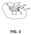
- Fig. 2 shows a detailed view of one of the contact surface 4.
- the contact surfaces 4 may, for example, be configured in the form of conductor tracks or in the form of flat band conductors.
- the back of the solar element 2 is covered by a second cover 5.
- the second cover 5 may, for example, be configured in the form of a glass sheet or a compound foil.
- the second cover 5 comprises an opening 6 in the region of the contact surface 4.
- a connection box having a housing 7, which covers part of the back of the solar element 2, is attached to the back of the solar element 2.
- the housing 7 is preferably attached to the solar element 2 via an adhesive connection 16.
- a connecting element 8, which is connected to electric connection sockets 9 via electrical conductors, is arranged on the housing 7.
- Resiliently biased contact elements 10 are arranged between the connecting element 8 and the contact surfaces 4.
- the contact element 10 is configured in the form of a spring contact, which is connected to a connecting contact of the connecting element 8 by a first contact region and lies on a contact surface 4 by means of a second contact region.
- the spring contact 10 comprises a rounded contact surface in the second contact region. This rounded contact surface is, for example, achieved by the spring contact 10 being configured in a curved manner in the second contact region.
- the spring contact 10 is biased against the contact surface 4 via the second contact region.
- the spring contact which utilises its inherent spring stiffness, is biased against the contact surface 4 for biasing purposes.
- the spring contact is preferably produced from spring steel.
- the glass cover 3 having a solar element 2 and having a second cover 5 is attached to the housing 7 via an adhesive connection and/or a mechanical connection. Connecting lines may be attached to the connection sockets 9.
- the connecting element 8 accordingly also comprises two connecting contacts for connecting the two spring contacts 10.
- the second connecting contact is also connected to a second connection socket 9 in an electrically conductive manner.
- the housing 7 comprises a housing base 13 and a housing lid 15.
- the connecting element 8 is arranged on the base of the housing 13. Further openings 14 through which the spring contacts 10 are guided, as illustrated in Fig. 2, are provided in the regions above the contact surfaces 4 in the housing base 13.
- the base 13 has a substantially closed flat configuration in the other regions.
- the solar element 2 having the glass cover 3 and the second cover 5 is placed onto the housing base 13 and is connected to the housing 7 via an adhesive and/or a mechanical connection.
- This allows automated fastening of the connection socket and allows automated electrical contact to be made between the solar element 2 and the connecting element 8 as no soldered, clamp or screw connection is required between the contact surfaces of the solar element 2 and the connecting element 8.
- a simple permanently resilient contacting via a spring contact is used.
Landscapes
- Photovoltaic Devices (AREA)
Abstract
Description
Claims (6)
- Solar module (1) having a connection box having a housing (7) and having a solar element (2), wherein the housing (7) comprises a connecting element (8) for the connection of electrical connecting lines, wherein the connecting element (8) is connected to a contact surface (4) of the solar element (2) via a contact element (10), wherein voltage may be tapped from the solar element (2) via a contact surface (4), characterised in that the contact element (10) is resiliently biased against the contact surface (4) of the solar element (2).
- Solar module according to claim 1, characterised in that a spring contact (10), which is fixed between the connecting element (8) and the contact surface (4) and is biased onto the contact surface (4), is arranged as a contact element.
- Solar module according to claim 2, characterised in that the spring contact (10) comprises a contact region (12), which rests on the contact surface (4), and in that the contact region (12) having a rounded surface rests on the contact surface (4).
- Solar module according to any one of claims 1 to 3, characterised in that the solar element (2) is covered by a foil or a glass sheet (4), on the side on which the contact surface is arranged (4), and in that the foil or the glass sheet (4) comprises an opening (6), through which the contact element (10) is guided to the contact surface (4).
- Solar module according to any one of claims 1 to 4, characterised in that the connection box is attached to the solar module via an adhesive or mechanical connection.
- Method for producing a solar module (1) having a solar element (2) and a connection box, wherein the solar element (2) comprises at least one contact surface (4) for tapping electrical voltage, which is generated by the solar element (2), wherein the connection box comprises at least one contact element (10) for making electrical contact with a contact surface (4), characterised in that the connection box comprises a spring contact (10) as a contact element, in that the connection box having the spring contact (10) is placed on the solar element (2), wherein the spring contact (10) is pressed onto the contact surface (4) in a biased manner, and in that the connection box is attached to the solar element (2).
Applications Claiming Priority (2)
| Application Number | Priority Date | Filing Date | Title |
|---|---|---|---|
| DE102004025627 | 2004-05-25 | ||
| DE102004025627A DE102004025627A1 (en) | 2004-05-25 | 2004-05-25 | Solar module with connection element |
Publications (2)
| Publication Number | Publication Date |
|---|---|
| EP1601024A2 true EP1601024A2 (en) | 2005-11-30 |
| EP1601024A3 EP1601024A3 (en) | 2012-05-02 |
Family
ID=34936706
Family Applications (1)
| Application Number | Title | Priority Date | Filing Date |
|---|---|---|---|
| EP05010884A Withdrawn EP1601024A3 (en) | 2004-05-25 | 2005-05-19 | Solar module having a connecting element |
Country Status (4)
| Country | Link |
|---|---|
| US (1) | US7705234B2 (en) |
| EP (1) | EP1601024A3 (en) |
| JP (1) | JP2005340821A (en) |
| DE (1) | DE102004025627A1 (en) |
Cited By (8)
| Publication number | Priority date | Publication date | Assignee | Title |
|---|---|---|---|---|
| FR2922362A1 (en) * | 2007-10-16 | 2009-04-17 | Avancis Gmbh & Co Kg | IMPROVEMENTS TO A CONNECTION HOUSING FOR ELEMENTS CAPABLE OF COLLECTING LIGHT. |
| WO2009086874A1 (en) * | 2008-01-08 | 2009-07-16 | Yamaichi Electronics Deutschland Gmbh | Socket, use, solar panel, contact element, and method |
| WO2009129405A3 (en) * | 2008-04-16 | 2010-10-14 | Molex Incorporated | Solar panel junction box |
| WO2012065772A1 (en) * | 2010-11-15 | 2012-05-24 | Robert Bosch Gmbh | Junction box of a solar cell module, solar cell module and method for producing same |
| ITMI20110933A1 (en) * | 2011-05-24 | 2012-11-25 | Moncada Solar Equipment Srl | PHOTOVOLTAIC PANEL AND ELECTRIC CONNECTOR FOR PHOTOVOLTAIC PANELS |
| US8512050B2 (en) | 2008-04-16 | 2013-08-20 | Molex Incorporated | Solar panel junction box |
| EP3128670A1 (en) * | 2015-08-06 | 2017-02-08 | Armor | Method for connecting a flexible electronic device to an electrical wire |
| CN112290252A (en) * | 2019-07-24 | 2021-01-29 | Agc株式会社 | Electrical connection structure |
Families Citing this family (26)
| Publication number | Priority date | Publication date | Assignee | Title |
|---|---|---|---|---|
| US7662001B2 (en) * | 2006-05-15 | 2010-02-16 | Antaya Technologies Corporation | Electrical connector assembly |
| US20080283118A1 (en) * | 2007-05-17 | 2008-11-20 | Larankelo, Inc. | Photovoltaic ac inverter mount and interconnect |
| JP2009043842A (en) * | 2007-08-07 | 2009-02-26 | Sharp Corp | Solar cell module |
| DE102007043178A1 (en) * | 2007-09-11 | 2009-03-12 | Yamaichi Electronics Deutschland Gmbh | Junction box, solar panel, contact device and procedure |
| US20090084426A1 (en) * | 2007-09-28 | 2009-04-02 | Enphase Energy, Inc. | Universal interface for a photovoltaic module |
| WO2009116394A1 (en) * | 2008-03-17 | 2009-09-24 | シャープ株式会社 | Solar battery module and method for manufacturing solar battery module |
| JP5004835B2 (en) * | 2008-03-17 | 2012-08-22 | シャープ株式会社 | Solar cell module and method for manufacturing solar cell module |
| DE102008017522A1 (en) * | 2008-04-04 | 2009-10-08 | Günther Spelsberg GmbH & Co. KG | solar cell module |
| EP2113945A1 (en) * | 2008-04-30 | 2009-11-04 | 3S Swiss Solar Systems AG | Method for producing contact for solar cells |
| JPWO2010067466A1 (en) * | 2008-12-12 | 2012-05-17 | オーナンバ株式会社 | Solar cell module |
| DE102008062034B4 (en) * | 2008-12-12 | 2010-08-12 | Tyco Electronics Amp Gmbh | Connecting device for connection to a solar module and solar module with such a connection device |
| US8435056B2 (en) * | 2009-04-16 | 2013-05-07 | Enphase Energy, Inc. | Apparatus for coupling power generated by a photovoltaic module to an output |
| DE102009039370B4 (en) * | 2009-05-20 | 2013-12-05 | Gp Solar Gmbh | Solar cell module with at least one laminate film, another laminate film and a transverse connector and method for interconnecting solar cells in a solar cell module |
| DE102009036458A1 (en) * | 2009-08-06 | 2011-02-10 | Yamaichi Electronics Deutschland Gmbh | Solar module and method for producing the same |
| JP5605909B2 (en) | 2011-02-23 | 2014-10-15 | ホシデン株式会社 | Solar cell module terminal and solar cell module terminal box |
| US9118273B2 (en) | 2011-07-18 | 2015-08-25 | Enphase Energy, Inc. | Resilient mounting assembly for photovoltaic modules |
| JP5729648B2 (en) * | 2011-10-13 | 2015-06-03 | ホシデン株式会社 | Terminal box for solar cell module |
| JP5790940B2 (en) * | 2011-12-19 | 2015-10-07 | ホシデン株式会社 | Terminal box |
| CN103390668A (en) * | 2012-05-10 | 2013-11-13 | 苏州快可光伏电子股份有限公司 | Terminal box |
| US12150755B1 (en) | 2012-09-25 | 2024-11-26 | Micro Mobio Corporation | Integrated display with antenna system and method |
| US11272861B1 (en) | 2012-09-25 | 2022-03-15 | Micro Mobio Corporation | Personal cloud with a plurality of modular capabilities |
| USD734653S1 (en) | 2012-11-09 | 2015-07-21 | Enphase Energy, Inc. | AC module mounting bracket |
| US11095248B2 (en) * | 2017-11-30 | 2021-08-17 | TE Connectivity Services Gmbh | Solar junction box |
| DE102018125742A1 (en) * | 2018-10-17 | 2020-04-23 | Hanwha Q Cells Gmbh | Mounting frame for a photovoltaic module |
| FR3107143A1 (en) | 2020-02-06 | 2021-08-13 | Armor Beautiful Light | Electronic device intended to be connected to an electrical connector and associated connection method |
| EP4472066A1 (en) * | 2023-06-03 | 2024-12-04 | Meyer Burger (Switzerland) AG | Frame-attached junction box for solar cell modules |
Family Cites Families (21)
| Publication number | Priority date | Publication date | Assignee | Title |
|---|---|---|---|---|
| US3611270A (en) * | 1969-04-08 | 1971-10-05 | Thomas & Betts Corp | Electrical wiring connector block |
| CH667553A5 (en) * | 1985-10-09 | 1988-10-14 | Woertz Oskar | SCREWLESS ELECTRICAL TERMINAL. |
| JPH0618813Y2 (en) * | 1987-09-11 | 1994-05-18 | ダイキョー・ベバスト株式会社 | Sunroof equipment |
| US4798545A (en) * | 1987-09-23 | 1989-01-17 | United Technologies Automotive, Inc. | Electrical terminal receptacle and electrical component housing adapted for the same |
| DE4022928C1 (en) * | 1990-07-19 | 1992-02-06 | Webasto Ag Fahrzeugtechnik, 8035 Stockdorf, De | |
| EP0521189A1 (en) * | 1991-07-05 | 1993-01-07 | Siemens Solar GmbH | Electrical terminal for a solar module |
| US5503684A (en) * | 1994-12-30 | 1996-04-02 | Silicon Energy Corporation | Termination system for solar panels |
| JP3437885B2 (en) * | 1995-05-31 | 2003-08-18 | シャープ株式会社 | Solar cell module and method of manufacturing the same |
| WO1998025325A1 (en) * | 1996-11-30 | 1998-06-11 | Atlantis Solar Systeme Ag | Clamping device for connecting electrical connections of solar elements |
| JPH10270734A (en) * | 1997-03-27 | 1998-10-09 | Canon Inc | Solar cell module |
| JP3459754B2 (en) * | 1997-06-24 | 2003-10-27 | キヤノン株式会社 | Terminal box for solar cell module, method of connecting the same, and solar cell module |
| DE19813324B4 (en) * | 1998-03-26 | 2004-07-22 | Webasto Systemkomponenten Gmbh | Solar cover for vehicles and method for producing such |
| JP2000200919A (en) * | 1998-10-30 | 2000-07-18 | Canon Inc | Solar cell module and solar cell array |
| JP2000357812A (en) * | 1999-04-15 | 2000-12-26 | Canon Inc | Solar cell module and power generator |
| TW428812U (en) * | 1999-10-15 | 2001-04-01 | Hon Hai Prec Ind Co Ltd | Electrical connector |
| EP1102354B1 (en) * | 1999-11-17 | 2008-05-28 | Tyco Electronics AMP GmbH | Apparatus for contacting foil conductors, in particular of a solar module |
| JP4208130B2 (en) * | 2002-06-20 | 2009-01-14 | タイコ エレクトロニクス アンプ ゲゼルシャフト ミット ベシュレンクテル ハウツンク | Plug type electrical connector |
| DE10241728B4 (en) * | 2002-09-10 | 2006-03-16 | Saint-Gobain Glass Deutschland Gmbh | Multilayer electrical heatable surface element |
| DE60304485T2 (en) * | 2002-09-10 | 2006-10-12 | Saint-Gobain Glass France | CONNECTING DEVICE FOR A FLAT ELEMENT COMPRISING MULTIPLE LAYERS EQUIPPED WITH ELECTRICAL FUNCTIONAL ELEMENTS AND FLAT ELEMENT |
| DE20311184U1 (en) * | 2003-07-21 | 2004-02-19 | Tyco Electronics Amp Gmbh | Junction box for connection to a solar panel |
| DE20311183U1 (en) * | 2003-07-21 | 2004-07-08 | Tyco Electronics Amp Gmbh | Junction box for a solar panel and solar panel |
-
2004
- 2004-05-25 DE DE102004025627A patent/DE102004025627A1/en not_active Ceased
-
2005
- 2005-05-19 EP EP05010884A patent/EP1601024A3/en not_active Withdrawn
- 2005-05-23 JP JP2005149190A patent/JP2005340821A/en active Pending
- 2005-05-25 US US11/136,867 patent/US7705234B2/en active Active
Cited By (12)
| Publication number | Priority date | Publication date | Assignee | Title |
|---|---|---|---|---|
| FR2922362A1 (en) * | 2007-10-16 | 2009-04-17 | Avancis Gmbh & Co Kg | IMPROVEMENTS TO A CONNECTION HOUSING FOR ELEMENTS CAPABLE OF COLLECTING LIGHT. |
| WO2009050145A1 (en) * | 2007-10-16 | 2009-04-23 | Avancis Gmbh & Co. Kg | Improvements to a connection housing for light-capturing elements |
| CN101939845B (en) * | 2007-10-16 | 2013-01-02 | 法国圣戈班玻璃厂 | Improvements made to junction boxes for components capable of harvesting light |
| WO2009086874A1 (en) * | 2008-01-08 | 2009-07-16 | Yamaichi Electronics Deutschland Gmbh | Socket, use, solar panel, contact element, and method |
| US8075326B2 (en) | 2008-01-08 | 2011-12-13 | Yamaichi Electronics Co., Ltd. | Junction box and contact element for photovoltaic modules |
| WO2009129405A3 (en) * | 2008-04-16 | 2010-10-14 | Molex Incorporated | Solar panel junction box |
| US8512050B2 (en) | 2008-04-16 | 2013-08-20 | Molex Incorporated | Solar panel junction box |
| WO2012065772A1 (en) * | 2010-11-15 | 2012-05-24 | Robert Bosch Gmbh | Junction box of a solar cell module, solar cell module and method for producing same |
| ITMI20110933A1 (en) * | 2011-05-24 | 2012-11-25 | Moncada Solar Equipment Srl | PHOTOVOLTAIC PANEL AND ELECTRIC CONNECTOR FOR PHOTOVOLTAIC PANELS |
| EP3128670A1 (en) * | 2015-08-06 | 2017-02-08 | Armor | Method for connecting a flexible electronic device to an electrical wire |
| CN112290252A (en) * | 2019-07-24 | 2021-01-29 | Agc株式会社 | Electrical connection structure |
| CN112290252B (en) * | 2019-07-24 | 2024-03-29 | Agc株式会社 | Electric connection structure |
Also Published As
| Publication number | Publication date |
|---|---|
| US7705234B2 (en) | 2010-04-27 |
| EP1601024A3 (en) | 2012-05-02 |
| JP2005340821A (en) | 2005-12-08 |
| US20060000504A1 (en) | 2006-01-05 |
| DE102004025627A1 (en) | 2005-12-22 |
Similar Documents
| Publication | Publication Date | Title |
|---|---|---|
| EP1601024A2 (en) | Solar module having a connecting element | |
| US11770597B2 (en) | Heating device for camera module and camera module having same | |
| EP1501133B1 (en) | Connecting box for connecting to a solar panel | |
| US7648371B2 (en) | Electrical connector arrangement for knife contacts | |
| US7655859B2 (en) | Connector for a solar module | |
| US9239152B2 (en) | LED holder | |
| US7938661B2 (en) | Photovoltaic module connector assembly | |
| US20110168228A1 (en) | Solar panel junction box | |
| EP2279529A2 (en) | Solar panel junction box | |
| JP2013093307A (en) | Wiring module for cell | |
| US9853331B2 (en) | Cover for batteries | |
| JP2010102977A (en) | Connector | |
| RU2006137292A (en) | DEVICE WITH ELECTRIC MOTOR AND MAIN PRINTED BOARD AND METHOD OF INSTALLATION | |
| US9065218B2 (en) | Making contact in a force-optimized manner between electrical loads and printed circuit boards | |
| TW200511920A (en) | System to mount electrical modules | |
| EP1367643A3 (en) | Electronic module | |
| JP2009253078A (en) | Electric connection structure of circuit bodies | |
| JP7560509B2 (en) | Busbar Module | |
| JPS6325881Y2 (en) | ||
| US20120125402A1 (en) | Solar cell mounting system | |
| JPH09259951A (en) | Terminal connection structure of electronic device | |
| JPH1050433A (en) | Board-connecting structure | |
| KR20030039457A (en) | Lamp structure for vehicle license plate | |
| JPH1125842A (en) | Fuse-mounting device |
Legal Events
| Date | Code | Title | Description |
|---|---|---|---|
| PUAI | Public reference made under article 153(3) epc to a published international application that has entered the european phase |
Free format text: ORIGINAL CODE: 0009012 |
|
| AK | Designated contracting states |
Kind code of ref document: A2 Designated state(s): AT BE BG CH CY CZ DE DK EE ES FI FR GB GR HU IE IS IT LI LT LU MC NL PL PT RO SE SI SK TR |
|
| AX | Request for extension of the european patent |
Extension state: AL BA HR LV MK YU |
|
| PUAL | Search report despatched |
Free format text: ORIGINAL CODE: 0009013 |
|
| AK | Designated contracting states |
Kind code of ref document: A3 Designated state(s): AT BE BG CH CY CZ DE DK EE ES FI FR GB GR HU IE IS IT LI LT LU MC NL PL PT RO SE SI SK TR |
|
| AX | Request for extension of the european patent |
Extension state: AL BA HR LV MK YU |
|
| RIC1 | Information provided on ipc code assigned before grant |
Ipc: H01L 31/02 20060101ALI20120329BHEP Ipc: H01L 31/048 20060101AFI20120329BHEP |
|
| AKY | No designation fees paid | ||
| REG | Reference to a national code |
Ref country code: DE Ref legal event code: R108 |
|
| REG | Reference to a national code |
Ref country code: DE Ref legal event code: R108 Effective date: 20130109 |
|
| STAA | Information on the status of an ep patent application or granted ep patent |
Free format text: STATUS: THE APPLICATION IS DEEMED TO BE WITHDRAWN |
|
| 18D | Application deemed to be withdrawn |
Effective date: 20121103 |