EP1600894A2 - Apparatus and method for correcting the color of an image - Google Patents
Apparatus and method for correcting the color of an image Download PDFInfo
- Publication number
- EP1600894A2 EP1600894A2 EP05251888A EP05251888A EP1600894A2 EP 1600894 A2 EP1600894 A2 EP 1600894A2 EP 05251888 A EP05251888 A EP 05251888A EP 05251888 A EP05251888 A EP 05251888A EP 1600894 A2 EP1600894 A2 EP 1600894A2
- Authority
- EP
- European Patent Office
- Prior art keywords
- image
- reference patches
- color
- color component
- displayed
- Prior art date
- Legal status (The legal status is an assumption and is not a legal conclusion. Google has not performed a legal analysis and makes no representation as to the accuracy of the status listed.)
- Granted
Links
Images


Classifications
-
- H—ELECTRICITY
- H04—ELECTRIC COMMUNICATION TECHNIQUE
- H04M—TELEPHONIC COMMUNICATION
- H04M1/00—Substation equipment, e.g. for use by subscribers
- H04M1/72—Mobile telephones; Cordless telephones, i.e. devices for establishing wireless links to base stations without route selection
- H04M1/724—User interfaces specially adapted for cordless or mobile telephones
- H04M1/72403—User interfaces specially adapted for cordless or mobile telephones with means for local support of applications that increase the functionality
-
- G—PHYSICS
- G09—EDUCATION; CRYPTOGRAPHY; DISPLAY; ADVERTISING; SEALS
- G09G—ARRANGEMENTS OR CIRCUITS FOR CONTROL OF INDICATING DEVICES USING STATIC MEANS TO PRESENT VARIABLE INFORMATION
- G09G5/00—Control arrangements or circuits for visual indicators common to cathode-ray tube indicators and other visual indicators
- G09G5/02—Control arrangements or circuits for visual indicators common to cathode-ray tube indicators and other visual indicators characterised by the way in which colour is displayed
- G09G5/06—Control arrangements or circuits for visual indicators common to cathode-ray tube indicators and other visual indicators characterised by the way in which colour is displayed using colour palettes, e.g. look-up tables
-
- G—PHYSICS
- G06—COMPUTING; CALCULATING OR COUNTING
- G06T—IMAGE DATA PROCESSING OR GENERATION, IN GENERAL
- G06T11/00—2D [Two Dimensional] image generation
- G06T11/001—Texturing; Colouring; Generation of texture or colour
-
- G—PHYSICS
- G08—SIGNALLING
- G08B—SIGNALLING OR CALLING SYSTEMS; ORDER TELEGRAPHS; ALARM SYSTEMS
- G08B21/00—Alarms responsive to a single specified undesired or abnormal condition and not otherwise provided for
- G08B21/18—Status alarms
-
- H—ELECTRICITY
- H04—ELECTRIC COMMUNICATION TECHNIQUE
- H04N—PICTORIAL COMMUNICATION, e.g. TELEVISION
- H04N9/00—Details of colour television systems
- H04N9/64—Circuits for processing colour signals
- H04N9/68—Circuits for processing colour signals for controlling the amplitude of colour signals, e.g. automatic chroma control circuits
-
- H—ELECTRICITY
- H04—ELECTRIC COMMUNICATION TECHNIQUE
- H04M—TELEPHONIC COMMUNICATION
- H04M2201/00—Electronic components, circuits, software, systems or apparatus used in telephone systems
- H04M2201/34—Microprocessors
-
- H—ELECTRICITY
- H04—ELECTRIC COMMUNICATION TECHNIQUE
- H04M—TELEPHONIC COMMUNICATION
- H04M2201/00—Electronic components, circuits, software, systems or apparatus used in telephone systems
- H04M2201/36—Memories
-
- H—ELECTRICITY
- H04—ELECTRIC COMMUNICATION TECHNIQUE
- H04M—TELEPHONIC COMMUNICATION
- H04M2201/00—Electronic components, circuits, software, systems or apparatus used in telephone systems
- H04M2201/40—Electronic components, circuits, software, systems or apparatus used in telephone systems using speech recognition
Definitions
- the present invention relates to an image display device such as a monitor for displaying an image, and more particularly, to an apparatus and a method for correcting color of an image to be displayed on an image display device.
- gray components of an image to be displayed via the image display device do not include non-gray components.
- the gamma characteristics of R, G, and B channels are not identical.
- gray components of an image to be displayed include non-gray components. Accordingly, in a conventional color-correcting method, the color reproduction characteristics of an image display device are found out using a colorimetric apparatus, and then non-gray components are removed from gray components of an image using the color reproduction characteristics.
- the conventional color-correcting method has a disadvantage in that a user of an image display device cannot correct the gray color reproduction characteristics of the image display device without a high-priced colorimetric apparatus.
- an apparatus for correcting the color of an image to be displayed on an image display device includes: a user interface which displays each of N (which is a predetermined positive number greater than or equal to "1") reference patches, removes non-gray components from the displayed reference patch depending on characteristics of a user's visual system, and outputs the reference patches from which the non-gray components have been removed as adjusted reference patches; a table generator which generates at least one lookup table that has as addresses color component values the image may have and stores color component values of the adjusted reference patches as data; and a color corrector which addresses the at least one lookup table using the color component values of the image to read data corresponding to the color component values of the image and outputs the read data as the result of correcting color of the image.
- N which is a predetermined positive number greater than or equal to "1"
- a method of correcting the color of an image to be displayed on an image display device includes: displaying each of N (which is a predetermined positive number greater than or equal to "1 ") reference patches, removing non-gray components from the reference patches depending on the characteristics of a user's visual system, and determining the reference patches from which the non-gray components have been removed as adjusted reference patches; generating at least one lookup table that has as addresses color component values the image may have and stores color component values of the adjusted reference patches as data; and addressing the at least one lookup table using the color component values of the image to read data corresponding to the color component values of the image and determining the read data as the result of correcting color of the image.
- N which is a predetermined positive number greater than or equal to "1 ”
- the present invention provides an image color-correcting apparatus for adjusting the characteristics of an image display device using only the characteristics of a user's visual system to correct color of an image using the adjusted characteristics of the image display device.
- the present invention also provides an image color-correcting method of adjusting the characteristics of an image display device using only the characteristics of a user's visual system to correct color of an image using the adjusted characteristics of the image display device.
- FIG. 1 is a block diagram of an apparatus for correcting the color of an image, according to a preferred embodiment of the present invention.
- the apparatus includes a user interface 10, a table generator 12, and a color corrector 14.
- the apparatus of FIG. 1 corrects the color of an image displayed on an image display device as follows.
- the image display device refers to a monitor or the like.
- the user interface 10 displays each of N reference patches on the image display device, removes non-gray components from the displayed reference patches depending on the characteristics of a user's visual system, and outputs the reference patches from which the non-gray components have been removed as adjusted reference patches to the table generator 12.
- N is a predetermined positive number greater than equal to "1", where the greater the predetermined positive number, the better.
- the user interface 10 displays a plurality of pairs one by one.
- each of the plurality of pairs includes a reference patch and a background.
- Each background pairing with each reference patch is pre-determined.
- the user interface 10 removes non-gray components from the reference patches of the displayed pairs depending on the characteristics of the user's visual system and matches luminances of the displayed reference patches with luminances of the displayed backgrounds depending on the characteristics of the user's visual system.
- the user interface 10 outputs the reference patches, from which the non-gray components have been removed and the luminances of which have matched with the luminances of the displayed backgrounds, as adjusted reference patches.
- the table generator 12 generates at least one lookup table (LUT) which stores as addresses color component values an image may have and color component values of the adjusted reference patches input from the user interface 10 as data, and outputs the generated at least one LUT to the color corrector 14.
- the color component values may refer to R, G, and B component values.
- the LUTs for storing the R, G, and B component values, respectively, may be generated separately.
- the LUT for the R component stores as addresses R component values the image may have and R component values of the adjusted reference patches as data.
- the color corrector 14 addresses at least one LUT using color component values of an image to be displayed which are input as address of LUT via an input node IN1, reads data corresponding to the color component values from the at least one LUT, and outputs the read data as the result of correcting color of the image to be displayed via an output node OUT1.
- FIG. 2 is a block diagram of the user interface 10 of FIG. 1, according to a preferred embodiment of the present invention.
- a user interface 10A includes a luminance manipulator 32, a chroma component manipulator 34, and an adjusted reference patch generator 36.
- the luminance manipulator 32 is manipulated by a user, who desires to match the luminances of the displayed reference patches with the luminances of the displayed backgrounds which are a pair with the displayed reference patches, to match the luminances of the displayed reference patches with the luminances of the displayed backgrounds and outputs the manipulation results to the adjusted reference patch generator 36.
- the user manipulates the luminance manipulator 32 to match the luminances of the displayed reference patches with the luminances of the displayed backgrounds based on the characteristics of the user's visual system.
- the chroma component manipulator 34 is manipulated by a user, who desires to remove the non-gray components from the displayed reference patches, to remove the non-gray components from the displayed reference patches and outputs the removal results to the adjusted reference patch generator 36.
- the user manipulates the chroma component manipulator 34 to remove the non-gray components from the displayed reference patches based on the characteristics of the user's visual system.
- the adjusted reference patch generator 36 generates the adjusted reference patches using the reference patches, the luminances of which have been manipulated by the luminance manipulator 32 and from which the non-gray components have been removed by the chroma component manipulator 34, and outputs the adjusted reference patches to the color corrector 14 via an output node OUT2.
- FIG. 3 is a view for showing the external appearance of the user interface 10 of FIG. 1, according to a preferred embodiment of the present invention.
- the user interface 10 includes a reference patch 50, a background 52, gray balance cursors 54 and 58, a gray balance guide map 56, a group of reference patches 60, a group of adjusted reference patches 62, and a luminance manipulating portion 64 having a slide bar 66.
- the group of reference patches 60 includes seven reference patches 80 through 92
- the group of adjusted reference patches 62 includes seven adjusted reference patches 100 through 112.
- the gray balance guide map 56 and the gray balance cursors 54 and 58 correspond to the chroma component manipulator 34 of FIG. 2.
- the gray balance guide map 56 represents christeners of a plurality of chroma components in different locations on a two-dimensional space. For example, as shown in FIG. 3, christeners of yellow, red, magenta, blue, cyan, and green may be expressed as "Yellow”, “Red”, “Magenta”, “Blue”, “Cyan”, and “Green".
- the gray balance cursors 54 and 58 are located in the reference patch 50 and the gray balance guide map 56, respectively, and may be manipulated by the user so as to move the same distance at the same time and in the same direction.
- the gray balance cursor 54 in the reference patch 50 also moves the same distance as that by which the gray balance cursor 58 moves, from the time when the gray balance cursor 58 moves, in the left horizontal direction.
- a chroma component designated by the arbitrary christener may be gradually removed from the reference patch 50.
- the chroma component designated by the arbitrary christener may be gradually removed from the reference patch 50.
- the user moves the gray balance cursor 58 in the left horizontal direction toward the christener "Red” until the R component is removed from the reference patch 50.
- the gray balance cursor 58 gets closer to the namer "Red"
- a larger amount of non-gray component i.e., the R component
- the user determines the distance the user moves the gray balance cursor 58 toward a christener, based on the characteristics of the user's visual system.
- the luminance manipulating portion 64 of FIG. 3 corresponds to the luminance manipulator 34 of FIG. 2.
- the reference patch 50 may become dark or bright according to the left or right movement of the slide bar 66 of the luminance manipulating portion 64.
- the user can horizontally move the slide bar 66 by manipulating the pointing device to match the luminance of the reference patch 50 with the luminance of the background 52.
- the reference patch 50 is displayed to have the same luminance as the selected reference patch.
- the reference patch 50 is displayed to have the same luminance as the reference patch 88.
- the adjustment of the luminance characteristics of the reference patch through the manipulation of the slide bar 66 and the removal of the non-gray components from the reference patch through the manipulation of the gray balance cursor 58 results in obtaining adjusted reference patches for the respective reference patches of the group of reference patches 60.
- the respective adjusted reference patches of the group of adjusted reference patches 62 are the results obtained by adjusting the luminance of the reference patch 50 using the luminance manipulating portion 64 and removing the non-gray component from the reference patch 50 using the gray balance cursor 58.
- the reference patch 88 is selected to display the reference patch 50 as shown in FIG. 3
- the luminance of the reference patch 50 is adjusted by the luminance manipulator 32, and the non-gray component is removed from the reference patch 50 by the chroma component manipulator 34, as shown in FIG. 3, the adjusted reference patch 108 is generated.
- the user interface 10 of FIG. 3 may not include the group of reference patches 60 and the group of adjusted reference patches 62.
- the user interface 10 is not limited to the case of FIG. 3.
- the reference patch 50, the gray balance cursors 54 and 58, the group of reference patches 60, the group of adjusted reference patches 62, the slide bar 66, and the gray balance guide map 56 may have various shapes and patterns.
- a pattern of the gray balance cursor 54 in the reference patch 50 may be identical to a pattern of the background 52 so that the user further exactly removes the non-gray component from the reference patch 50.
- respective backgrounds which are displayed to pair with respective reference patches by the user interface 10 of FIG. 1, may have a pattern in which at least two of black, white, and gray lines cross each other.
- lines in the backgrounds adjacent lines of the same color do not exceed "3". This is because it is difficult to match the luminance of the reference patch with the luminance of the background in view of the characteristics of the user's visual system when more than three lines with the same color are adjacent to one another.
- FIGS. 4A through 4E are views for showing examples of backgrounds.
- reference numbers 130 and 150 denote first and second gray lines, respectively.
- luminances of backgrounds may vary depending on the kind and number of lines included in the backgrounds, i.e., the rates of black, gray, and white lines.
- each of the figures in the parentheses in the column of "Background Pattern” denotes the number of adjacent lines in each background.
- the first, second, third, fourth, and fifth backgrounds correspond to backgrounds shown in FIGS. 4A through 4E, respectively.
- the first gray lines 130 shown in FIG. 4A have the same color component values as color component values of adjusted reference patch that are determined for reference patch displayed together with a background shown in FIG. 4B.
- the adjusted reference patch of the reference patch displayed along with the background of FIG. 4B must be obtained prior to the adjusted reference patch of reference patch displayed together with a background of FIG. 4A.
- the dependency of the color component value of the first gray lines 130 included in the background of FIG. 4A on the adjusted reference patch of the reference patches displayed with the background of FIG. 4B is ascribed to the point that the number of adjacent black lines of FIG. 4B is equal to the number of adjacent black lines of FIG. 4A and the number of lines between the black lines of FIG. 4A is equal to the number of lines between the black lines of FIG. 4B.
- the second gray lines 150 have the same color component values as that of the adjusted reference patch that are determined for reference patch displayed with a background of FIG. 4D.
- the adjusted reference patch of the reference patch displayed together with the background of FIG. 4D must be obtained prior to the adjusted reference patch for reference patch displayed along with a background of FIG. 4E.
- the dependency of the color component value of the second gray lines 150 included in the background of FIG. 4E on the adjusted reference patch of the reference patch displayed together with the background of FIG. 4D is attributed to the point that the number of adjacent black lines of FIG. 4E is equal to the number of adjacent black lines of FIG. 4D and the number of lines between black lines of FIG. 4E is equal to the number of lines between black lines of FIG. 4D.
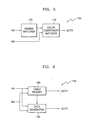
- FIG. 5 is a block diagram of the table generator 12 of FIG. 1, according to a preferred embodiment of the present invention.
- a table generator 12A includes a gamma matcher 170 and a color component matcher 172.
- the gamma matcher 170 matches a luminance of each of N backgrounds, which are input from the user interface 10 via an input node IN2, with color component values an image may have using a gamma function and outputs the matching results to the color component matcher 172.
- the component matcher 172 analyzes the matching results input from the gamma matcher 170, matches the color component values the image may have with the color component values of the adjusted reference patch, which are input from the user interface 10 via an input node IN3, and outputs the matching results as at least one LUT via an output node OUT3.
- R, G, and B color component values V an image may have are the same, and R', G', and B' denote R, G, and B color component values of adjusted reference patch, respectively.
- R',G',B' (0, 0, 0) denote color component values of a zero th adjusted reference patch generated for a zero th reference patch pairing with a zero th background.
- R',G',B' (R2, G2, B2) denote color component values of a second adjusted reference patch generated for a second reference patch pairing with a second background.
- R',G',B' (R3, G3, B3) denote color component values of a third adjusted reference patch generated for a third reference patch pairing with a third background.
- R',G',B' (R4, G4, B4) denote color component values of a fourth adjusted reference patch generated for a fourth reference patch pairing with a fourth background.
- R',G',B' (R5, G5, B5) denote color component values of a fifth adjusted reference patch generated for a fifth reference patch pairing with a fifth background.
- R',G',B' (255, 255, 255) denote color component values of a sixth adjusted reference patch generated for a sixth reference patch pairing with a sixth background.
- the gamma matcher 170 of FIG. 5 substitutes the gamma function as in Equation 2 for luminances of seven backgrounds, i.e., zero th through sixth backgrounds, to calculate color component values V as shown in.Table 2.
- the gamma matcher 170 matches luminances of backgrounds with color component values V using a gamma function as shown in Table 2.
- the color component matcher 172 may match color component values R', G', and B' of the adjusted reference patches, which have been obtained for the respective reference patches by the user interface 10, with the color component values V, using the relationship between the luminances of the backgrounds and the color component values V, the relationship being the matching result of the gamma matcher 170.
- the color component matcher 172 receives the first adjusted reference patch for the first reference patch pairing with the first background from the user interface 10.
- the color component matcher 172 extracts color component values R1, G1, and B1 of the first adjusted reference patch, matches the extracted color component values R1, G1, and B1 with color component value "94" matched with the first background by the gamma matcher 170, and generates an LUT which has the color component value "94" as an address and stores the extracted color component values R1, G1, and B1 as data.
- color component values V may be matched with color component values R', G', and B' of the zero th through sixth adjusted reference patches.
- a first LUT is generated using the relationship between the color component values V and the color component values R' as shown in Table 2.
- a second LUT is generated using the relationship between the color component values V and the color component values R' as shown in Table 2.
- a third LUT is generated using the relationship between the color component values V and the color component values B' as shown in Table 2. Accordingly, the color component matcher 172 generates the generated first, second, and third LUTs and outputs the first, second, and third LUTs to the color corrector 14.
- FIG. 6 is a block diagram of the color corrector 14, according to a preferred embodiment of the present invention.
- a color corrector 14A includes a table reader 190 and a data generator 192.
- the table reader 190 receives at least one LUT from the table generator 12 via an input node IN4; addresses the at least one LUT using the color component values of the image to be displayed, which are input as the addresses via an input node IN5, to read data corresponding to the color component values of the image; and outputs the read data as the result of correcting color components of the image to be displayed via an output node OUT4.
- the data generator 192 predicts data corresponding to the color components values of the image using piecewise linear modeling and outputs the prediction results as the result of correcting color of the image via an output node OUT5.
- the data generator 192 may look up the at least LUT input via the input node IN4 to determine that the at least one LUT does not store data corresponding to the color component values of the image. According to another aspect of the present invention, the data generator 192 may determine that the at least one LUT does not store data corresponding to the color components values of the image, in response to a storage determination signal input from the table reader 190. For this purpose, the table reader 190 may output to the data generator 192 the storage determination signal for indicating that at least one LUT does not store data corresponding to the color components values of the image input via the input node IN5.
- FIG. 7 is an exemplary graph for showing a first LUT.
- the horizontal axis denotes R component values V an image may have, and the vertical axis denotes R component value R' of adjusted reference patch.
- the horizontal axis corresponds to addresses of the first LUT, and the vertical axis corresponds to data stored in the first LUT.
- the data generator 192 obtains a graph as shown in FIG. 7 using the first LUT input via the input node IN4.
- the data generator 192 marks the relationship between the color component values V and R' stored in the first LUT on the graph of FIG. 7 with dots 210, 212, 214, 216, 218, and 220 and then links the dots 210, 212, 214, 216, 218, and 220 with a straight line.
- the representation of an LUT on a graph and then the link of values which may be perceived through the LUT with a straight line refer to the piecewise linear modeling.
- FIG. 8 is a flowchart for explaining a method of correcting the color of an image, according to a preferred embodiment of the present invention.
- the method includes steps 300 and 302 of obtaining at least one LUT using adjusted reference patches obtained depending on the characteristics of a user's visual system and step 304 of correcting color of an image using the at least one LUT.
- steps 300, 302, and 304 may be performed by the user interface 10, the table generator 12, and the color corrector 14, respectively.
- each of N reference patches is displayed, non-gray components are removed from the displayed N reference patches depending on the characteristics of the user's visual system, and the reference patches from which the non-gray components have been removed are determined as adjusted reference patches.
- step 300 a plurality of pairs of reference patches and backgrounds are displayed pair by pair, non-gray components are removed from the displayed reference patches depending on the characteristics of a user's visual system, luminances of the displayed reference patches are matched with luminances of the displayed backgrounds depending on the characteristics of the user's visual system, and the reference patches from which the non-gray components have been removed and the luminances of which have matched with the luminances of the displayed backgrounds are determined as adjusted reference patches.
- step 302 at least one LUT, which has as addresses color component values an image may have and stores color component values of the adjusted reference patches as data, is generated.
- step 304 at least one LUT is addressed using the color component values of the image to read data corresponding to the color component values of the image and the read data is determined as the result of correcting color of the image.
- FIG. 9 is a flowchart for explaining an embodiment 300A of step 300 of FIG. 8.
- Step 300A includes steps 400, 402, 404, 406, 408, and 410 of obtaining adjusted reference patches for reference patches.
- a variable n is initialized to, for example, "1 ".
- step 402 a pair of n th reference patch and n th background is displayed.
- step 404 a luminance of the n th reference patch matches with a luminance of the n th background depending on the characteristics of the user's visual system, and an adjusted reference patch is generated based on matching result. For example, a user determines depending on the characteristics of the user's visual system whether the luminance of the n th reference patch seems identical to the luminance of the n th background.
- the user determines that the luminance of the n th reference patch does not seem identical to the luminance of the n th background, the user adjusts the luminance of the n th reference patch so as to match with the luminance of the n th background.
- a non-gray component is removed from the displayed n th reference patch depending on the characteristics of the user's visual system, and an adjusted reference patch is generated based on the removal result. For example, the user determines depending on the characteristics of the user's visual system whether the displayed n th reference patch includes the non-gray component. If the user determines that the displayed n th reference patch includes the non-gray component, the user removes the non-gray component from the n th reference patch until the non-gray component is completely removed from the n th reference patch.
- step 408 a determination is made as to whether the variable n is equal to N. In other words, a determination is made as to whether steps 404 and 406 have been completely performed on all of reference patches.
- step 408 If in step 408, it is determined that the variable n is equal to N, the process moves on to step 302 to generate an LUT. If in step 408, it is determined that the variable n is not equal to N, in step 410, the variable n increases by "1 " and the process returns to step 402.
- step 300A of FIG. 9 may not include step 404.
- step 406 is performed after step 402.
- step 404 of FIG. 9 may be performed not between steps 402 and 406 but between steps 406 and 408.
- step 406 is performed after step 402
- step 404 is performed after step 406, and step 408 is performed after step 404.
- the above-described image color-correcting apparatus and method according to the present invention can be adopted to edit an image displayed on an image display device.
- the luminance characteristics of an image display device can be corrected depending on the characteristics of a user's visual system without using a high-priced colorimetric apparatus.
- non-gray components which may be generated during the reproduction of a black and white image, can be removed.
- a user interface screen as shown in FIG. 3 a user can relatively easily adjust a reference patch depending on the characteristics of the user's visual system. As a result, the user can conveniently correct the color of an image to be displayed.
Abstract
Description
- The present invention relates to an image display device such as a monitor for displaying an image, and more particularly, to an apparatus and a method for correcting color of an image to be displayed on an image display device.
- In general, when the gamma characteristics of red (R), green (G), and blue (B) channels are the same in an image display device, gray components of an image to be displayed via the image display device do not include non-gray components. However, in most image display devices, the gamma characteristics of R, G, and B channels are not identical. Thus, gray components of an image to be displayed include non-gray components. Accordingly, in a conventional color-correcting method, the color reproduction characteristics of an image display device are found out using a colorimetric apparatus, and then non-gray components are removed from gray components of an image using the color reproduction characteristics.
- Consequently, the conventional color-correcting method has a disadvantage in that a user of an image display device cannot correct the gray color reproduction characteristics of the image display device without a high-priced colorimetric apparatus.
- According to an aspect of the present invention, there is provided an apparatus for correcting the color of an image to be displayed on an image display device. The apparatus includes: a user interface which displays each of N (which is a predetermined positive number greater than or equal to "1") reference patches, removes non-gray components from the displayed reference patch depending on characteristics of a user's visual system, and outputs the reference patches from which the non-gray components have been removed as adjusted reference patches; a table generator which generates at least one lookup table that has as addresses color component values the image may have and stores color component values of the adjusted reference patches as data; and a color corrector which addresses the at least one lookup table using the color component values of the image to read data corresponding to the color component values of the image and outputs the read data as the result of correcting color of the image.
- According to another aspect of the present invention, there is provided a method of correcting the color of an image to be displayed on an image display device. The method includes: displaying each of N (which is a predetermined positive number greater than or equal to "1 ") reference patches, removing non-gray components from the reference patches depending on the characteristics of a user's visual system, and determining the reference patches from which the non-gray components have been removed as adjusted reference patches; generating at least one lookup table that has as addresses color component values the image may have and stores color component values of the adjusted reference patches as data; and addressing the at least one lookup table using the color component values of the image to read data corresponding to the color component values of the image and determining the read data as the result of correcting color of the image.
- The present invention provides an image color-correcting apparatus for adjusting the characteristics of an image display device using only the characteristics of a user's visual system to correct color of an image using the adjusted characteristics of the image display device.
- The present invention also provides an image color-correcting method of adjusting the characteristics of an image display device using only the characteristics of a user's visual system to correct color of an image using the adjusted characteristics of the image display device.
- The above and other features and advantages of the present invention will become more apparent by describing in detail exemplary embodiments thereof with reference to the attached drawings in which:
- FIG. 1 is a block diagram of an apparatus for correcting the color of an image, according to a preferred embodiment of the present invention;
- FIG. 2 is a block diagram of a user interface of FIG. 1, according to a preferred embodiment of the present invention;
- FIG. 3 is a view for showing the external appearance of the user interface of FIG. 1, according to a preferred embodiment of the present invention;
- FIGS. 4A through 4E are views for showing examples of backgrounds;
- FIG. 5 is a block diagram of a table generator of FIG. 1, according to a preferred embodiment of the present invention;
- FIG. 6 is a block diagram of a color corrector of FIG. 1, according to a preferred embodiment of the present invention;
- FIG. 7 is an exemplary graph for showing a first lookup table;
- FIG. 8 is a flowchart for explaining a method of correcting the color of an image, according to a preferred embodiment of the present invention; and
- FIG. 9 is a flowchart for explaining
step 300 of FIG. 8, according to a preferred embodiment of the present invention. -
- Hereinafter, the structure and operation of an apparatus for correcting the color of an image, according to the present invention, will be described in detail with reference to the attached drawings.
- FIG. 1 is a block diagram of an apparatus for correcting the color of an image, according to a preferred embodiment of the present invention. Referring to FIG. 1, the apparatus includes a
user interface 10, atable generator 12, and acolor corrector 14. - The apparatus of FIG. 1 corrects the color of an image displayed on an image display device as follows. Here, the image display device refers to a monitor or the like.
- According to an aspect of the present invention, the
user interface 10 displays each of N reference patches on the image display device, removes non-gray components from the displayed reference patches depending on the characteristics of a user's visual system, and outputs the reference patches from which the non-gray components have been removed as adjusted reference patches to thetable generator 12. Here, N is a predetermined positive number greater than equal to "1", where the greater the predetermined positive number, the better. - According to another aspect of the present invention, the
user interface 10 displays a plurality of pairs one by one. Here, each of the plurality of pairs includes a reference patch and a background. Each background pairing with each reference patch is pre-determined. For example, luminances LB and LP of a background and a reference patch which are a pair may have the relationship as shown in Equation 1: - The
user interface 10 removes non-gray components from the reference patches of the displayed pairs depending on the characteristics of the user's visual system and matches luminances of the displayed reference patches with luminances of the displayed backgrounds depending on the characteristics of the user's visual system. Here, theuser interface 10 outputs the reference patches, from which the non-gray components have been removed and the luminances of which have matched with the luminances of the displayed backgrounds, as adjusted reference patches. - The
table generator 12 generates at least one lookup table (LUT) which stores as addresses color component values an image may have and color component values of the adjusted reference patches input from theuser interface 10 as data, and outputs the generated at least one LUT to thecolor corrector 14. Here, the color component values may refer to R, G, and B component values. Also, the LUTs for storing the R, G, and B component values, respectively, may be generated separately. For example, the LUT for the R component stores as addresses R component values the image may have and R component values of the adjusted reference patches as data. - The
color corrector 14 addresses at least one LUT using color component values of an image to be displayed which are input as address of LUT via an input node IN1, reads data corresponding to the color component values from the at least one LUT, and outputs the read data as the result of correcting color of the image to be displayed via an output node OUT1. - FIG. 2 is a block diagram of the
user interface 10 of FIG. 1, according to a preferred embodiment of the present invention. Referring to FIG. 2, auser interface 10A includes aluminance manipulator 32, achroma component manipulator 34, and an adjustedreference patch generator 36. - The
luminance manipulator 32 is manipulated by a user, who desires to match the luminances of the displayed reference patches with the luminances of the displayed backgrounds which are a pair with the displayed reference patches, to match the luminances of the displayed reference patches with the luminances of the displayed backgrounds and outputs the manipulation results to the adjustedreference patch generator 36. In other words, the user manipulates theluminance manipulator 32 to match the luminances of the displayed reference patches with the luminances of the displayed backgrounds based on the characteristics of the user's visual system. - The
chroma component manipulator 34 is manipulated by a user, who desires to remove the non-gray components from the displayed reference patches, to remove the non-gray components from the displayed reference patches and outputs the removal results to the adjustedreference patch generator 36. In other words, the user manipulates thechroma component manipulator 34 to remove the non-gray components from the displayed reference patches based on the characteristics of the user's visual system. - The adjusted
reference patch generator 36 generates the adjusted reference patches using the reference patches, the luminances of which have been manipulated by theluminance manipulator 32 and from which the non-gray components have been removed by thechroma component manipulator 34, and outputs the adjusted reference patches to thecolor corrector 14 via an output node OUT2. - FIG. 3 is a view for showing the external appearance of the
user interface 10 of FIG. 1, according to a preferred embodiment of the present invention. Theuser interface 10 includes areference patch 50, abackground 52,gray balance cursors balance guide map 56, a group ofreference patches 60, a group of adjustedreference patches 62, and aluminance manipulating portion 64 having aslide bar 66. - For example, when N=7, as shown in FIG. 3, the group of
reference patches 60 includes sevenreference patches 80 through 92, and the group of adjustedreference patches 62 includes seven adjustedreference patches 100 through 112. - The gray
balance guide map 56 and thegray balance cursors chroma component manipulator 34 of FIG. 2. Here, the graybalance guide map 56 represents christeners of a plurality of chroma components in different locations on a two-dimensional space. For example, as shown in FIG. 3, christeners of yellow, red, magenta, blue, cyan, and green may be expressed as "Yellow", "Red", "Magenta", "Blue", "Cyan", and "Green". Here, thegray balance cursors reference patch 50 and the graybalance guide map 56, respectively, and may be manipulated by the user so as to move the same distance at the same time and in the same direction. For example, when the user moves thegray balance cursor 58 toward a location of the christener "Red", i.e., in the left horizontal direction, with a pointing device such as a mouse or the like, thegray balance cursor 54 in thereference patch 50 also moves the same distance as that by which thegray balance cursor 58 moves, from the time when thegray balance cursor 58 moves, in the left horizontal direction. As thegray balance cursor 58 in the graybalance guide map 56 approaches an arbitrary christener, a chroma component designated by the arbitrary christener may be gradually removed from thereference patch 50. Alternatively, as thegray balance cursor 58 in the graybalance guide map 56 becomes far from the arbitrary christener, the chroma component designated by the arbitrary christener may be gradually removed from thereference patch 50. - For example, when the
reference patch 50 includes an R component as a non-gray component, the user moves thegray balance cursor 58 in the left horizontal direction toward the christener "Red" until the R component is removed from thereference patch 50. As thegray balance cursor 58 gets closer to the namer "Red", a larger amount of non-gray component, i.e., the R component, is removed from thereference patch 50. Here, the user determines the distance the user moves thegray balance cursor 58 toward a christener, based on the characteristics of the user's visual system. - The
luminance manipulating portion 64 of FIG. 3 corresponds to theluminance manipulator 34 of FIG. 2. For example, thereference patch 50 may become dark or bright according to the left or right movement of theslide bar 66 of theluminance manipulating portion 64. Thus, the user can horizontally move theslide bar 66 by manipulating the pointing device to match the luminance of thereference patch 50 with the luminance of thebackground 52. - In FIG. 3, when the user selects one of the
reference patches 80 through 92 of the group ofreference patches 60 by manipulating the pointing device, thereference patch 50 is displayed to have the same luminance as the selected reference patch. For example, when the user selects thereference patch 88 from the group ofreference patches 60, thereference patch 50 is displayed to have the same luminance as thereference patch 88. As described above, the adjustment of the luminance characteristics of the reference patch through the manipulation of theslide bar 66 and the removal of the non-gray components from the reference patch through the manipulation of thegray balance cursor 58 results in obtaining adjusted reference patches for the respective reference patches of the group ofreference patches 60. In other words, the respective adjusted reference patches of the group of adjustedreference patches 62 are the results obtained by adjusting the luminance of thereference patch 50 using theluminance manipulating portion 64 and removing the non-gray component from thereference patch 50 using thegray balance cursor 58. For example, when thereference patch 88 is selected to display thereference patch 50 as shown in FIG. 3, the luminance of thereference patch 50 is adjusted by theluminance manipulator 32, and the non-gray component is removed from thereference patch 50 by thechroma component manipulator 34, as shown in FIG. 3, the adjustedreference patch 108 is generated. - According to the present invention, the
user interface 10 of FIG. 3 may not include the group ofreference patches 60 and the group of adjustedreference patches 62. - Also, the
user interface 10 according to the present invention is not limited to the case of FIG. 3. For example, thereference patch 50, thegray balance cursors reference patches 60, the group of adjustedreference patches 62, theslide bar 66, and the graybalance guide map 56 may have various shapes and patterns. - According to the present invention, a pattern of the
gray balance cursor 54 in thereference patch 50 may be identical to a pattern of thebackground 52 so that the user further exactly removes the non-gray component from thereference patch 50. - Moreover, according to the present invention, respective backgrounds, which are displayed to pair with respective reference patches by the
user interface 10 of FIG. 1, may have a pattern in which at least two of black, white, and gray lines cross each other. Here, it is preferable that of lines in the backgrounds, adjacent lines of the same color do not exceed "3". This is because it is difficult to match the luminance of the reference patch with the luminance of the background in view of the characteristics of the user's visual system when more than three lines with the same color are adjacent to one another. - FIGS. 4A through 4E are views for showing examples of backgrounds. Here,
reference numbers - When the maximum luminance the image display device can represent is "100", as shown in Table 1, luminances of backgrounds may vary depending on the kind and number of lines included in the backgrounds, i.e., the rates of black, gray, and white lines.
Classification Background Luminance (%) Background Pattern First Background 11.1 Black Line (2), First Gray Line (1) Second Background 33.3 Black Line (2), White Line (1) Third Background 50.0 Black Line (1), White Line (1) Fourth Background 66.7 Black Line (1), White Line (2) Fifth Background 88.9 Second Gray Line (1), White Line (2) - As shown in Table 1, each of the figures in the parentheses in the column of "Background Pattern" denotes the number of adjacent lines in each background. The first, second, third, fourth, and fifth backgrounds correspond to backgrounds shown in FIGS. 4A through 4E, respectively.
- Here, the first
gray lines 130 shown in FIG. 4A have the same color component values as color component values of adjusted reference patch that are determined for reference patch displayed together with a background shown in FIG. 4B. For this purpose, the adjusted reference patch of the reference patch displayed along with the background of FIG. 4B must be obtained prior to the adjusted reference patch of reference patch displayed together with a background of FIG. 4A. The dependency of the color component value of the firstgray lines 130 included in the background of FIG. 4A on the adjusted reference patch of the reference patches displayed with the background of FIG. 4B is ascribed to the point that the number of adjacent black lines of FIG. 4B is equal to the number of adjacent black lines of FIG. 4A and the number of lines between the black lines of FIG. 4A is equal to the number of lines between the black lines of FIG. 4B. - The second
gray lines 150 have the same color component values as that of the adjusted reference patch that are determined for reference patch displayed with a background of FIG. 4D. For this purpose, the adjusted reference patch of the reference patch displayed together with the background of FIG. 4D must be obtained prior to the adjusted reference patch for reference patch displayed along with a background of FIG. 4E. The dependency of the color component value of the secondgray lines 150 included in the background of FIG. 4E on the adjusted reference patch of the reference patch displayed together with the background of FIG. 4D is attributed to the point that the number of adjacent black lines of FIG. 4E is equal to the number of adjacent black lines of FIG. 4D and the number of lines between black lines of FIG. 4E is equal to the number of lines between black lines of FIG. 4D. - FIG. 5 is a block diagram of the
table generator 12 of FIG. 1, according to a preferred embodiment of the present invention. Referring to FIG. 5, atable generator 12A includes agamma matcher 170 and acolor component matcher 172. - The
gamma matcher 170 matches a luminance of each of N backgrounds, which are input from theuser interface 10 via an input node IN2, with color component values an image may have using a gamma function and outputs the matching results to thecolor component matcher 172. - For example, luminance Y of each of the N backgrounds may match with a color component value V an image may have using a gamma function represented as in Equation 2:
- The
component matcher 172 analyzes the matching results input from thegamma matcher 170, matches the color component values the image may have with the color component values of the adjusted reference patch, which are input from theuser interface 10 via an input node IN3, and outputs the matching results as at least one LUT via an output node OUT3. - For the comprehension of the
table generator 12A of FIG. 5, it is assumed that N=7, a gamma function is represented as in Equation 2, gamma is set to "2.2", and B=255. In this case, Table 2 may be referred to, in order to generate LUTs.Classification Background Luminance V R' G' B' Zeroth Background 0 0 0 0 0 First Background 0.111 94 R1 G1 B1 Second Background 0.334 155 R2 G2 B2 Third Background 0.505 187 R3 G3 B3 Fourth Background 0.666 212 R4 G4 B4 Fifth Background 0.891 242 R5 G5 B5 Sixth Background 1 255 255 255 255 - It is assumed that in Table 2, R, G, and B color component values V an image may have are the same, and R', G', and B' denote R, G, and B color component values of adjusted reference patch, respectively. For example, (R',G',B')=(0, 0, 0) denote color component values of a zeroth adjusted reference patch generated for a zeroth reference patch pairing with a zeroth background. (R',G',B')=(R1, G1, B1) denote color component values of a first adjusted reference patch generated for a first reference patch pairing with a first background. (R',G',B')=(R2, G2, B2) denote color component values of a second adjusted reference patch generated for a second reference patch pairing with a second background. (R',G',B')=(R3, G3, B3) denote color component values of a third adjusted reference patch generated for a third reference patch pairing with a third background. (R',G',B')=(R4, G4, B4) denote color component values of a fourth adjusted reference patch generated for a fourth reference patch pairing with a fourth background. (R',G',B')=(R5, G5, B5) denote color component values of a fifth adjusted reference patch generated for a fifth reference patch pairing with a fifth background. (R',G',B')=(255, 255, 255) denote color component values of a sixth adjusted reference patch generated for a sixth reference patch pairing with a sixth background.
- The
gamma matcher 170 of FIG. 5 substitutes the gamma function as in Equation 2 for luminances of seven backgrounds, i.e., zeroth through sixth backgrounds, to calculate color component values V as shown in.Table 2. In other words, thegamma matcher 170 matches luminances of backgrounds with color component values V using a gamma function as shown in Table 2. - Here, seven reference patches, i.e., the zeroth through sixth references patches, are in advance determined to be pair with seven backgrounds, i.e., the zeroth through sixth backgrounds, respectively. Therefore, the
color component matcher 172 may match color component values R', G', and B' of the adjusted reference patches, which have been obtained for the respective reference patches by theuser interface 10, with the color component values V, using the relationship between the luminances of the backgrounds and the color component values V, the relationship being the matching result of thegamma matcher 170. - For example, the
color component matcher 172 receives the first adjusted reference patch for the first reference patch pairing with the first background from theuser interface 10. Here, thecolor component matcher 172 extracts color component values R1, G1, and B1 of the first adjusted reference patch, matches the extracted color component values R1, G1, and B1 with color component value "94" matched with the first background by thegamma matcher 170, and generates an LUT which has the color component value "94" as an address and stores the extracted color component values R1, G1, and B1 as data. Using such a method, as shown in Table 2, color component values V may be matched with color component values R', G', and B' of the zeroth through sixth adjusted reference patches. For example, a first LUT is generated using the relationship between the color component values V and the color component values R' as shown in Table 2. A second LUT is generated using the relationship between the color component values V and the color component values R' as shown in Table 2. A third LUT is generated using the relationship between the color component values V and the color component values B' as shown in Table 2. Accordingly, thecolor component matcher 172 generates the generated first, second, and third LUTs and outputs the first, second, and third LUTs to thecolor corrector 14. - FIG. 6 is a block diagram of the
color corrector 14, according to a preferred embodiment of the present invention. Referring to FIG. 6, acolor corrector 14A includes atable reader 190 and adata generator 192. - The
table reader 190 receives at least one LUT from thetable generator 12 via an input node IN4; addresses the at least one LUT using the color component values of the image to be displayed, which are input as the addresses via an input node IN5, to read data corresponding to the color component values of the image; and outputs the read data as the result of correcting color components of the image to be displayed via an output node OUT4. - Here, when the at least one LUT does not store data corresponding to the color component values of the image to be displayed, which are input via the input node IN5, the
data generator 192 predicts data corresponding to the color components values of the image using piecewise linear modeling and outputs the prediction results as the result of correcting color of the image via an output node OUT5. - According to an aspect of the present invention, the
data generator 192 may look up the at least LUT input via the input node IN4 to determine that the at least one LUT does not store data corresponding to the color component values of the image. According to another aspect of the present invention, thedata generator 192 may determine that the at least one LUT does not store data corresponding to the color components values of the image, in response to a storage determination signal input from thetable reader 190. For this purpose, thetable reader 190 may output to thedata generator 192 the storage determination signal for indicating that at least one LUT does not store data corresponding to the color components values of the image input via the input node IN5. - For the comprehension of the
color corrector 14A of FIG. 6, it is supposed that at least one LUT is generated based on Table 2. For example, when color component values, [V(R, G, B)=(94, 94, 94)], of an image are input to an LUT, color component values R1, G1, and B1 are output as corrected color for the color component values [V(R, G, B)=(94, 94, 94)] from the LUT. - FIG. 7 is an exemplary graph for showing a first LUT. Referring to FIG. 7, the horizontal axis denotes R component values V an image may have, and the vertical axis denotes R component value R' of adjusted reference patch. In other words, the horizontal axis corresponds to addresses of the first LUT, and the vertical axis corresponds to data stored in the first LUT.
- The
data generator 192 obtains a graph as shown in FIG. 7 using the first LUT input via the input node IN4. In other words, thedata generator 192 marks the relationship between the color component values V and R' stored in the first LUT on the graph of FIG. 7 withdots dots - When the LUT does not store data corresponding to the color component value of the image input via the input node IN5, i.e., the color component value V of the image does not belong to the color component values shown in Table 2, the
data generator 192 may predict data R' corresponding to corrected color for the color component value V of the image with reference to the graph of FIG. 7. For example, in a case where V=170, since the first LUT does not store data R' corresponding to V=170, data R2' on the graph of FIG. 7 is predicted as data corresponding to V=170. Here, thedata generator 192 outputs the predicted data R2' as the correction result of V=170 via the output node OUT5. - A method of correcting the color of an image, according to the present invention, will now be explained with reference to the attached drawings.
- FIG. 8 is a flowchart for explaining a method of correcting the color of an image, according to a preferred embodiment of the present invention. The method includes
steps - The method of FIG. 8 may be performed using the apparatus of FIG. 1. In other words,
steps user interface 10, thetable generator 12, and thecolor corrector 14, respectively. - According to an aspect of the present invention, in
step 300, each of N reference patches is displayed, non-gray components are removed from the displayed N reference patches depending on the characteristics of the user's visual system, and the reference patches from which the non-gray components have been removed are determined as adjusted reference patches. - According to another aspect of the present invention, in
step 300, a plurality of pairs of reference patches and backgrounds are displayed pair by pair, non-gray components are removed from the displayed reference patches depending on the characteristics of a user's visual system, luminances of the displayed reference patches are matched with luminances of the displayed backgrounds depending on the characteristics of the user's visual system, and the reference patches from which the non-gray components have been removed and the luminances of which have matched with the luminances of the displayed backgrounds are determined as adjusted reference patches. - After
step 300, instep 302, at least one LUT, which has as addresses color component values an image may have and stores color component values of the adjusted reference patches as data, is generated. - After
step 302, instep 304, at least one LUT is addressed using the color component values of the image to read data corresponding to the color component values of the image and the read data is determined as the result of correcting color of the image. - FIG. 9 is a flowchart for explaining an
embodiment 300A ofstep 300 of FIG. 8.Step 300A includessteps - According to an aspect of the present invention, in
step 400, a variable n is initialized to, for example, "1 ". Afterstep 400, instep 402, a pair of nth reference patch and nth background is displayed. Afterstep 402, instep 404, a luminance of the nth reference patch matches with a luminance of the nth background depending on the characteristics of the user's visual system, and an adjusted reference patch is generated based on matching result. For example, a user determines depending on the characteristics of the user's visual system whether the luminance of the nth reference patch seems identical to the luminance of the nth background. If the user determines that the luminance of the nth reference patch does not seem identical to the luminance of the nth background, the user adjusts the luminance of the nth reference patch so as to match with the luminance of the nth background. - After
step 404, instep 406, a non-gray component is removed from the displayed nth reference patch depending on the characteristics of the user's visual system, and an adjusted reference patch is generated based on the removal result. For example, the user determines depending on the characteristics of the user's visual system whether the displayed nth reference patch includes the non-gray component. If the user determines that the displayed nth reference patch includes the non-gray component, the user removes the non-gray component from the nth reference patch until the non-gray component is completely removed from the nth reference patch. Afterstep 406, instep 408, a determination is made as to whether the variable n is equal to N. In other words, a determination is made as to whethersteps - If in
step 408, it is determined that the variable n is equal to N, the process moves on to step 302 to generate an LUT. If instep 408, it is determined that the variable n is not equal to N, instep 410, the variable n increases by "1 " and the process returns to step 402. - According to another aspect of the present invention,
step 300A of FIG. 9 may not includestep 404. In this case,step 406 is performed afterstep 402. - According to yet another aspect of the present invention, step 404 of FIG. 9 may be performed not between
steps steps step 406 is performed afterstep 402,step 404 is performed afterstep 406, and step 408 is performed afterstep 404. - The above-described image color-correcting apparatus and method according to the present invention can be adopted to edit an image displayed on an image display device.
- As described above, in an apparatus and method for correcting the color of an image, according to the present invention, the luminance characteristics of an image display device can be corrected depending on the characteristics of a user's visual system without using a high-priced colorimetric apparatus. Also, non-gray components, which may be generated during the reproduction of a black and white image, can be removed. For example, with a user interface screen as shown in FIG. 3, a user can relatively easily adjust a reference patch depending on the characteristics of the user's visual system. As a result, the user can conveniently correct the color of an image to be displayed.
- While the present invention has been particularly shown and described with reference to exemplary embodiments thereof, it will be understood by those of ordinary skill in the art that various changes in form and details may be made therein without departing from the scope of the present invention as defined by the following claims.
Claims (13)
- An apparatus for correcting the color of an image to be displayed on an image display device, the apparatus comprising:a user interface (10) arranged to display each of N (which is a predetermined positive number greater than or equal to "1") reference patches, remove non-gray components from the displayed reference patch depending on characteristics of a user's visual system, and output the reference patches from which the non-gray components have been removed as adjusted reference patches;a table generator (12) arranged to generate at least one lookup table that has as addresses color component values the image may have and store color component values of the adjusted reference patches as data; anda color corrector (14) which address the at least one lookup table using the color component values of the image to read data corresponding to the color component values of the image and output the read data as the result of correcting color of the image.
- The apparatus of claim 1, wherein the user interface is arranged to display a plurality of pairs of reference patches and backgrounds pair by pair, remove non-gray components from the displayed reference patches depending on the characteristics of the user's visual system, match luminances of the displayed reference patches with luminances of the displayed backgrounds depending on the characteristics of the user's visual system, and output the reference patches from which the non-gray components have been removed and the luminances of which have matched with the luminances of the backgrounds as the adjusted reference patches, wherein each of the plurality of pairs includes one reference patch and one background and the backgrounds pairing with the reference patches are pre-determined.
- The apparatus of claim 2, wherein the user interface comprises:a luminance manipulator (32) arranged to be manipulated by the user who desires to match the luminance of the displayed reference patch with the luminance of the displayed background which is a pair with the displayed reference patch;a color component manipulator (34) arranged to be manipulated by the user who desires to remove the non-gray components from the displayed reference patches; andan adjusted reference patch generator (36) arranged to generate the adjusted reference patches for the reference patches using the manipulation results obtained by the luminance manipulator and the color component manipulator.
- The apparatus of claim 3, wherein the color component manipulator comprises:wherein as the gray balance cursor (58) within the gray balance guide map (56) gets closer to an arbitrary christener, a chroma component designated by the arbitrary christener is gradually removed from the reference patches.a gray balance guide map (56) arranged to represent christeners of a plurality of chroma components in different locations on a two-dimensional space; andgray balance cursors (54,58) which are provided within the reference patches (50) and the gray balance guide map (56) and are arranged to be manipulated by the user so as to move together an identical distance in an identical direction,
- The apparatus of claim 4, wherein a pattern of the gray balance cursors (54) within the reference patches (50) is identical to a pattern of the backgrounds.
- The apparatus of any of claims 2 to 5, wherein the backgrounds have a pattern in which at least two of black, white, and gray lines cross each other.
- The apparatus of claim 6, wherein in the background, the number of adjacent lines with same color do not exceed "3".
- The apparatus of any of claims 2 to 7, wherein the table generator comprises:a gamma matcher (170) arranged to match the luminances of the N backgrounds with the color component values the image may have using a gamma function; anda color component matcher (172) arranged to analyse the matching results, match the color components values the image may have with the color component values of the adjusted reference patches, and output the matching results as at least one lookup table.
- The apparatus of any preceding claim, wherein the color corrector comprises:a table reader (190) arranged to address the at least one lookup table using the color component values of the image to read the data corresponding to the color component values of the image and outputs the read data as the result of correcting color of the image; anda data generator (192) arranged to, when the at least one lookup table does not store the data corresponding to the color component values of the image, predict the data using piecewise linear modeling and output the prediction results as the result of correcting color of the image.
- A method of correcting the color of an image to be displayed on an image display device, the method comprising:displaying each of N (which is a predetermined positive number greater than or equal to "1 ") reference patches, removing non-gray components from the reference patches depending on the characteristics of a user's visual system, and determining the reference patches from which the non-gray components have been removed as adjusted reference patches;generating at least one lookup table that has as addresses color component values the image may have and stores color component values of the adjusted reference patches as data; andaddressing the at least one lookup table using the color component values of the image to read data corresponding to the color component values of the image and determining the read data as the result of correcting color of the image.
- The method of claim 10, wherein a plurality of pairs of reference patches and backgrounds are displayed pair by pair, non-gray components are removed from the displayed reference patches depending on the characteristics of the user's visual system, luminances of the displayed reference patches match with luminances of the displayed backgrounds depending on the characteristics of the user's visual system, and the reference patches from which the non-gray components have been removed and the luminances of which have matched with the luminances of the backgrounds are determined as the adjusted reference patches, wherein each of the plurality of pairs includes one reference patch and one background and the backgrounds pairing with the reference patches are pre-determined.
- The method of claim 11, wherein the determination of the adjusted reference patches comprises:initializing a variable n;displaying an nth reference patch and an nth background making a pair, together;removing the non-gray component from the displayed nth reference patch depending on the characteristics of the user's visual system;determining whether the variable n is equal to N, and if it is determined that the variable n is equal to N, proceeding to the generation of the at least lookup table; andif it is determined that the variable n is not equal to N, increasing the variable n by "1" and returning to the displaying of the nth reference patch and the nth background.
- The method of claim 12, where the determination of the adjusted reference patches further comprises:matching a luminance of the nth reference patch with a luminance of the nth background depending on the characteristics of the user's visual system.
Applications Claiming Priority (2)
| Application Number | Priority Date | Filing Date | Title |
|---|---|---|---|
| KR1020040021818A KR100601947B1 (en) | 2004-03-30 | 2004-03-30 | Apparatus and method for correcting color of image |
| KR2004021818 | 2004-03-30 |
Publications (3)
| Publication Number | Publication Date |
|---|---|
| EP1600894A2 true EP1600894A2 (en) | 2005-11-30 |
| EP1600894A3 EP1600894A3 (en) | 2008-04-02 |
| EP1600894B1 EP1600894B1 (en) | 2010-12-29 |
Family
ID=34940644
Family Applications (1)
| Application Number | Title | Priority Date | Filing Date |
|---|---|---|---|
| EP05251888A Expired - Fee Related EP1600894B1 (en) | 2004-03-30 | 2005-03-24 | Apparatus and method for correcting the color of an image |
Country Status (5)
| Country | Link |
|---|---|
| US (1) | US7688326B2 (en) |
| EP (1) | EP1600894B1 (en) |
| JP (1) | JP4991120B2 (en) |
| KR (1) | KR100601947B1 (en) |
| DE (1) | DE602005025561D1 (en) |
Families Citing this family (12)
| Publication number | Priority date | Publication date | Assignee | Title |
|---|---|---|---|---|
| KR100837744B1 (en) | 2005-08-10 | 2008-06-13 | 세이코 엡슨 가부시키가이샤 | Image display device and image adjusting method |
| JP2007156215A (en) * | 2005-12-07 | 2007-06-21 | Matsushita Electric Ind Co Ltd | Display device |
| JP2007208529A (en) * | 2006-01-31 | 2007-08-16 | Canon Inc | Display controller, control method and program |
| JP2007205804A (en) * | 2006-01-31 | 2007-08-16 | Canon Inc | Display device, display method, and control program |
| KR101232177B1 (en) * | 2006-11-27 | 2013-02-12 | 엘지디스플레이 주식회사 | Method and Apparatus for Compensating Line Defect of Flat Display |
| KR101348369B1 (en) | 2007-11-12 | 2014-01-07 | 삼성전자주식회사 | Color conversion method and apparatus for display device |
| US8130240B2 (en) * | 2008-10-24 | 2012-03-06 | Microsoft Corporation | Target display for gamma calibration |
| KR101324090B1 (en) * | 2009-10-09 | 2013-10-31 | 한국전자통신연구원 | Method and apparatus for providing display information for color calibration of dsplay device |
| US8503776B2 (en) | 2009-10-09 | 2013-08-06 | Electronics And Telecommunications Research Institute | Apparatus and method for providing display information for color calibration of display device |
| EP2573671A2 (en) * | 2011-09-26 | 2013-03-27 | Samsung Electronics Co., Ltd | Colour calibration method and apparatus |
| US20140168253A1 (en) * | 2012-12-18 | 2014-06-19 | Canon Kabushiki Kaisha | Color processing apparatus and method |
| KR102617938B1 (en) * | 2016-08-23 | 2023-12-27 | 삼성디스플레이 주식회사 | Method of driving display device and display device performing the same |
Citations (6)
| Publication number | Priority date | Publication date | Assignee | Title |
|---|---|---|---|---|
| EP0313796A2 (en) * | 1987-10-26 | 1989-05-03 | Tektronix, Inc. | Computer display color control and selection system |
| US5483259A (en) * | 1994-04-12 | 1996-01-09 | Digital Light & Color Inc. | Color calibration of display devices |
| US5754222A (en) * | 1996-03-08 | 1998-05-19 | Eastman Kodak Company | Visual characterization using display model |
| US6078309A (en) * | 1998-05-22 | 2000-06-20 | Way Tech Development, Inc. | System and method for visually measuring color characteristics of a display |
| EP1073883A1 (en) * | 1998-04-24 | 2001-02-07 | Adobe Systems, Inc. | Method to estimate the white point on a display device |
| US6686953B1 (en) * | 2000-03-01 | 2004-02-03 | Joseph Holmes | Visual calibration target set method |
Family Cites Families (10)
| Publication number | Priority date | Publication date | Assignee | Title |
|---|---|---|---|---|
| JPH11252589A (en) * | 1998-03-03 | 1999-09-17 | Dainippon Printing Co Ltd | Color adjustment method for monitor and adjustment color chart used for it |
| JP3678000B2 (en) | 1998-05-27 | 2005-08-03 | 富士通株式会社 | Display device adjustment method and display device adjustment device |
| US6233560B1 (en) | 1998-12-16 | 2001-05-15 | International Business Machines Corporation | Method and apparatus for presenting proximal feedback in voice command systems |
| US20040227769A9 (en) * | 2000-03-31 | 2004-11-18 | Imation Corp. | Color image display accuracy using comparison of colored objects to dithered background |
| US7119760B2 (en) * | 2000-03-31 | 2006-10-10 | Kodak Graphic Communications Canada Company | Color image display accuracy using green-limited gamma estimate |
| AU2001264994A1 (en) * | 2000-05-24 | 2001-12-03 | Kopin Corporation | Portable microdisplay system |
| JP2002055668A (en) * | 2000-08-10 | 2002-02-20 | Sharp Corp | Method for measuring input/output characteristics of display device, method for correcting image of the display device, method for preparing icc profile of the display device, storage medium with procedure for the methods stored thereon, and the display device |
| JP2003052057A (en) * | 2001-08-08 | 2003-02-21 | Hitachi Ltd | Stereoscopic vision image forming equipment using image conversion |
| US6919905B2 (en) * | 2001-09-28 | 2005-07-19 | Hewlett-Packard Development Company, L.P. | Method and device for visual calibration of displays |
| US7215813B2 (en) * | 2001-12-03 | 2007-05-08 | Apple Computer, Inc. | Method and apparatus for color correction |
-
2004
- 2004-03-30 KR KR1020040021818A patent/KR100601947B1/en active IP Right Grant
-
2005
- 2005-03-24 EP EP05251888A patent/EP1600894B1/en not_active Expired - Fee Related
- 2005-03-24 DE DE602005025561T patent/DE602005025561D1/en active Active
- 2005-03-30 JP JP2005097799A patent/JP4991120B2/en not_active Expired - Fee Related
- 2005-03-30 US US11/093,258 patent/US7688326B2/en not_active Expired - Fee Related
Patent Citations (6)
| Publication number | Priority date | Publication date | Assignee | Title |
|---|---|---|---|---|
| EP0313796A2 (en) * | 1987-10-26 | 1989-05-03 | Tektronix, Inc. | Computer display color control and selection system |
| US5483259A (en) * | 1994-04-12 | 1996-01-09 | Digital Light & Color Inc. | Color calibration of display devices |
| US5754222A (en) * | 1996-03-08 | 1998-05-19 | Eastman Kodak Company | Visual characterization using display model |
| EP1073883A1 (en) * | 1998-04-24 | 2001-02-07 | Adobe Systems, Inc. | Method to estimate the white point on a display device |
| US6078309A (en) * | 1998-05-22 | 2000-06-20 | Way Tech Development, Inc. | System and method for visually measuring color characteristics of a display |
| US6686953B1 (en) * | 2000-03-01 | 2004-02-03 | Joseph Holmes | Visual calibration target set method |
Also Published As
| Publication number | Publication date |
|---|---|
| KR20050097091A (en) | 2005-10-07 |
| DE602005025561D1 (en) | 2011-02-10 |
| JP4991120B2 (en) | 2012-08-01 |
| JP2005284292A (en) | 2005-10-13 |
| US7688326B2 (en) | 2010-03-30 |
| EP1600894A3 (en) | 2008-04-02 |
| EP1600894B1 (en) | 2010-12-29 |
| KR100601947B1 (en) | 2006-07-14 |
| US20050231741A1 (en) | 2005-10-20 |
Similar Documents
| Publication | Publication Date | Title |
|---|---|---|
| EP1600894A2 (en) | Apparatus and method for correcting the color of an image | |
| US20090060326A1 (en) | Image processing apparatus and method | |
| KR101348369B1 (en) | Color conversion method and apparatus for display device | |
| JP4364281B2 (en) | Display device | |
| US20030025835A1 (en) | Method for independently controlling hue or saturation of individual colors in a real time digital video image | |
| JP4398713B2 (en) | Color signal correcting apparatus and method, and video signal processing system and method using the same | |
| JPH10145582A (en) | Image processing method and device therefor | |
| KR101090060B1 (en) | Image forming apparatus and image forming method capable of revising gray image | |
| JP2010517075A (en) | Wide color gamut anaglyph | |
| EP1591994A1 (en) | Color space correction circuit in display device | |
| WO2000052938A1 (en) | Method of selective color control of digital video images | |
| US20070140558A1 (en) | Enhanced Color Correction Circuitry Capable of Employing Negative RGB Values | |
| US7671871B2 (en) | Graphical user interface for color correction using curves | |
| JP2004118442A (en) | Image color correction device, image color correction method, and image color correction program | |
| US7660015B2 (en) | Color data conversion apparatus and method | |
| US7450183B2 (en) | Method and apparatus for compensating for luminance of color signal | |
| KR100510308B1 (en) | Image processing device | |
| US7602400B2 (en) | Color adjusting method and color adjusting apparatus | |
| KR20100061389A (en) | Color gamut expansion method and display device | |
| US20060279811A1 (en) | Method for adjusting colors of image | |
| JP2007324665A (en) | Image correction apparatus and video display apparatus | |
| RU2353971C2 (en) | Scheme of colour correction per each tint | |
| JP2003076341A (en) | Sequential color display device | |
| JP2005184117A (en) | Color conversion apparatus and color conversion method | |
| JP3972471B2 (en) | Image display device and image display method |
Legal Events
| Date | Code | Title | Description |
|---|---|---|---|
| PUAI | Public reference made under article 153(3) epc to a published international application that has entered the european phase |
Free format text: ORIGINAL CODE: 0009012 |
|
| AK | Designated contracting states |
Kind code of ref document: A2 Designated state(s): AT BE BG CH CY CZ DE DK EE ES FI FR GB GR HU IE IS IT LI LT LU MC NL PL PT RO SE SI SK TR |
|
| AX | Request for extension of the european patent |
Extension state: AL BA HR LV MK YU |
|
| RIN1 | Information on inventor provided before grant (corrected) |
Inventor name: KIM, CHANGYEONG502-1305 JINSAN MAEUL Inventor name: CHOE, WONHEE Inventor name: CHO, CHEONYONG Inventor name: CHO, MINKI Inventor name: OK, HYUNWOOKC/O SAMSUNG ADVANCED INST. OF TECH. Inventor name: PARK, DUSIK301-1804 CHEONGMYEONG MAEUL DAWOO APT. Inventor name: LEE, SEONGDEOK435-1504 CHEONGMYEONG MAEUL Inventor name: KIM, DAEWON110-301 HYUNDAI BAEKJO TOWN APT. Inventor name: LEE, HOYOUNG |
|
| PUAL | Search report despatched |
Free format text: ORIGINAL CODE: 0009013 |
|
| AK | Designated contracting states |
Kind code of ref document: A3 Designated state(s): AT BE BG CH CY CZ DE DK EE ES FI FR GB GR HU IE IS IT LI LT LU MC NL PL PT RO SE SI SK TR |
|
| AX | Request for extension of the european patent |
Extension state: AL BA HR LV MK YU |
|
| RIC1 | Information provided on ipc code assigned before grant |
Ipc: H04N 9/73 20060101ALI20080227BHEP Ipc: H04N 17/02 20060101ALI20080227BHEP Ipc: H04N 1/60 20060101ALI20080227BHEP Ipc: G06T 11/00 20060101AFI20050930BHEP |
|
| 17P | Request for examination filed |
Effective date: 20080924 |
|
| 17Q | First examination report despatched |
Effective date: 20081024 |
|
| AKX | Designation fees paid |
Designated state(s): DE FR GB NL |
|
| GRAP | Despatch of communication of intention to grant a patent |
Free format text: ORIGINAL CODE: EPIDOSNIGR1 |
|
| GRAS | Grant fee paid |
Free format text: ORIGINAL CODE: EPIDOSNIGR3 |
|
| GRAA | (expected) grant |
Free format text: ORIGINAL CODE: 0009210 |
|
| AK | Designated contracting states |
Kind code of ref document: B1 Designated state(s): DE FR GB NL |
|
| REG | Reference to a national code |
Ref country code: GB Ref legal event code: FG4D |
|
| REF | Corresponds to: |
Ref document number: 602005025561 Country of ref document: DE Date of ref document: 20110210 Kind code of ref document: P |
|
| REG | Reference to a national code |
Ref country code: DE Ref legal event code: R096 Ref document number: 602005025561 Country of ref document: DE Effective date: 20110210 |
|
| REG | Reference to a national code |
Ref country code: NL Ref legal event code: T3 |
|
| PLBE | No opposition filed within time limit |
Free format text: ORIGINAL CODE: 0009261 |
|
| STAA | Information on the status of an ep patent application or granted ep patent |
Free format text: STATUS: NO OPPOSITION FILED WITHIN TIME LIMIT |
|
| 26N | No opposition filed |
Effective date: 20110930 |
|
| REG | Reference to a national code |
Ref country code: DE Ref legal event code: R097 Ref document number: 602005025561 Country of ref document: DE Effective date: 20110930 |
|
| REG | Reference to a national code |
Ref country code: FR Ref legal event code: PLFP Year of fee payment: 12 |
|
| REG | Reference to a national code |
Ref country code: FR Ref legal event code: PLFP Year of fee payment: 13 |
|
| REG | Reference to a national code |
Ref country code: FR Ref legal event code: PLFP Year of fee payment: 14 |
|
| PGFP | Annual fee paid to national office [announced via postgrant information from national office to epo] |
Ref country code: DE Payment date: 20200310 Year of fee payment: 16 Ref country code: GB Payment date: 20200311 Year of fee payment: 16 Ref country code: NL Payment date: 20200312 Year of fee payment: 16 |
|
| PGFP | Annual fee paid to national office [announced via postgrant information from national office to epo] |
Ref country code: FR Payment date: 20200227 Year of fee payment: 16 |
|
| REG | Reference to a national code |
Ref country code: DE Ref legal event code: R119 Ref document number: 602005025561 Country of ref document: DE |
|
| REG | Reference to a national code |
Ref country code: NL Ref legal event code: MM Effective date: 20210401 |
|
| GBPC | Gb: european patent ceased through non-payment of renewal fee |
Effective date: 20210324 |
|
| PG25 | Lapsed in a contracting state [announced via postgrant information from national office to epo] |
Ref country code: NL Free format text: LAPSE BECAUSE OF NON-PAYMENT OF DUE FEES Effective date: 20210401 Ref country code: FR Free format text: LAPSE BECAUSE OF NON-PAYMENT OF DUE FEES Effective date: 20210331 Ref country code: GB Free format text: LAPSE BECAUSE OF NON-PAYMENT OF DUE FEES Effective date: 20210324 Ref country code: DE Free format text: LAPSE BECAUSE OF NON-PAYMENT OF DUE FEES Effective date: 20211001 |