EP1600650A1 - Hydraulische Betätigungseinrichtung für eine Kraftfahrzeugkupplung - Google Patents
Hydraulische Betätigungseinrichtung für eine Kraftfahrzeugkupplung Download PDFInfo
- Publication number
- EP1600650A1 EP1600650A1 EP04012526A EP04012526A EP1600650A1 EP 1600650 A1 EP1600650 A1 EP 1600650A1 EP 04012526 A EP04012526 A EP 04012526A EP 04012526 A EP04012526 A EP 04012526A EP 1600650 A1 EP1600650 A1 EP 1600650A1
- Authority
- EP
- European Patent Office
- Prior art keywords
- channel
- fluid
- attenuator
- pressure chamber
- hydraulic actuator
- Prior art date
- Legal status (The legal status is an assumption and is not a legal conclusion. Google has not performed a legal analysis and makes no representation as to the accuracy of the status listed.)
- Granted
Links
Images


Classifications
-
- F—MECHANICAL ENGINEERING; LIGHTING; HEATING; WEAPONS; BLASTING
- F16—ENGINEERING ELEMENTS AND UNITS; GENERAL MEASURES FOR PRODUCING AND MAINTAINING EFFECTIVE FUNCTIONING OF MACHINES OR INSTALLATIONS; THERMAL INSULATION IN GENERAL
- F16D—COUPLINGS FOR TRANSMITTING ROTATION; CLUTCHES; BRAKES
- F16D48/00—External control of clutches
- F16D48/02—Control by fluid pressure
-
- F—MECHANICAL ENGINEERING; LIGHTING; HEATING; WEAPONS; BLASTING
- F16—ENGINEERING ELEMENTS AND UNITS; GENERAL MEASURES FOR PRODUCING AND MAINTAINING EFFECTIVE FUNCTIONING OF MACHINES OR INSTALLATIONS; THERMAL INSULATION IN GENERAL
- F16D—COUPLINGS FOR TRANSMITTING ROTATION; CLUTCHES; BRAKES
- F16D25/00—Fluid-actuated clutches
- F16D25/12—Details not specific to one of the before-mentioned types
- F16D25/14—Fluid pressure control
-
- F—MECHANICAL ENGINEERING; LIGHTING; HEATING; WEAPONS; BLASTING
- F16—ENGINEERING ELEMENTS AND UNITS; GENERAL MEASURES FOR PRODUCING AND MAINTAINING EFFECTIVE FUNCTIONING OF MACHINES OR INSTALLATIONS; THERMAL INSULATION IN GENERAL
- F16D—COUPLINGS FOR TRANSMITTING ROTATION; CLUTCHES; BRAKES
- F16D48/00—External control of clutches
- F16D48/02—Control by fluid pressure
- F16D2048/0215—Control by fluid pressure for damping of pulsations within the fluid system
-
- F—MECHANICAL ENGINEERING; LIGHTING; HEATING; WEAPONS; BLASTING
- F16—ENGINEERING ELEMENTS AND UNITS; GENERAL MEASURES FOR PRODUCING AND MAINTAINING EFFECTIVE FUNCTIONING OF MACHINES OR INSTALLATIONS; THERMAL INSULATION IN GENERAL
- F16D—COUPLINGS FOR TRANSMITTING ROTATION; CLUTCHES; BRAKES
- F16D2300/00—Special features for couplings or clutches
- F16D2300/22—Vibration damping
Definitions
- the invention relates to a hydraulic actuator for a motor vehicle clutch according to the preamble of claim 1.
- Hydraulic clutch actuation systems on motor vehicles have the undesirable Feature on that of the periodically firing internal combustion engine triggered axial vibrations via the friction clutch and its diaphragm spring transferred to the clutch release bearing and the associated disengaging become. These axial vibrations continue in a hydraulic pressure chamber, the by a donor and a slave cylinder, and a connecting them Hydraulic channel is limited and can cause an uncomfortable tingling sensation in the foot of a driver when touching the clutch pedal.
- the pressure pulsations can be limited by the use of one elastic pressure line, for example, made of a steel-rubber composite, steamed become.
- additional, designed as a so-called Kribbelfilter hydraulic damping elements are integrated.
- steel-rubber pipes increasingly through easier to manufacture and less expensive, replaced completely made of a plastic pressure lines, which at a Pressure load as a result of a clutch actuation one compared to the aforementioned Line type lower elasticity and thus have a lower volume absorption.
- the use of a hydraulic attenuator is special desirable.
- a generic attenuator for a hydraulic clutch actuation is with the WO 2004/015290 A1 become known, whose housing is located between two plug-in coupling elements extending main channel for connection to a Hydraulic line and a from a central region of the former laterally branching fluid port to the mouth in a pressure chamber of there as Membrane vibration damper formed attenuator has.
- the invention solves the problem with a hydraulic actuator for a Motor vehicle coupling with the features of claim 1.
- the inventor has recognized that pressure pulsations differ from that with the powertrain the vehicle associated slave cylinder in the direction of the master cylinder spread, be divided in the connection area of the attenuator and in a first, within the attenuator attenuating pulsation and in a second pulsation, which is a vibration of the piston in the master cylinder stimulates.
- it is suggested in the Connection region of the connection channel to the main channel flow influencing means for generating a substantially to the attenuator directed Form fluid flow, whereby a direct flow connection between the Donor and the slave cylinder is largely prevented.
- a pressure pulsation spreading in the system is almost completely absorbed the attenuator deflected and can be weakened there.
- This functionality thus corresponds to one with an inlet and an outlet fluid port to the main channel in series attenuator.
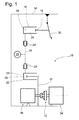
- Fig. 1 is a hydraulic actuating device 10 for actuating schematically a motor vehicle clutch 12, which on a chassis 14 of a Motor vehicle is arranged and wherein a master cylinder 16 with a piston 18th and a slave cylinder 20 are arranged with a piston 22 which together via plug-in couplings or hydraulic coupling elements 24 with a fluid 25 filled hydraulic line 26 are connected and a common pressure chamber Train 28.
- the piston 18 of the master cylinder 16 can be actuated by a pedal 30 be, whereupon the piston 22 of the slave cylinder 20 shifts and a clutch fork 32 for disengaging the clutch 12 on an internal combustion engine 34 trained drive unit controls.
- the coupling 12 is input side with the output shaft of the engine 34 and the output side with a transmission 36 connected.
- an attenuator 29 provided for damping of pressure pulsations, which via a Connecting channel 31 is connected, which branches off from a fluid main channel 27.
- the attenuator 29 may be in one piece, that is integral with the hydraulic line be executed or alternatively also via hydraulic coupling elements 24 with this be connected.
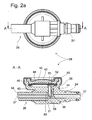
- FIG. 2 a shows a damping member 29 designed as a membrane oscillator a cylindrical housing 38 having a frontally arranged therein circular Steel sheet membrane 40 includes, in pressure pulsations of the hydraulic fluid Can perform vibrations. With a sudden rise in pressure, the Bulge membrane for a short time, thereby providing additional volume whereby a pressure pulsation can be alleviated.
- the membrane 40 is of a Housing cover 42 pressed against a ring land 43 and seals with a in a groove 44 lying O-ring seal 46, a fluid pressure chamber 48 relative to the Atmosphere off.
- the lid 42 is held by a bead 50 at the seat.
- the inner surface 52 of the lid 42 is concave shaped so that the membrane 40 cling to this when reaching a maximum allowable fluid pressure can and an overstretching of the membrane 40 and possibly bursting of the attenuator 29 can be avoided.
- a free end of a preferably made of the plastic PA 12th produced hydraulic line 26 with a molded-on this end housing 38th provided and thus fluid-tight connected thereto.
- the housing 38 is also made made of PA 12, but this is additionally structurally with a fiber material, preferably Reinforced glass fibers. It is essential that for the hydraulic line 26 and the housing 38 is a suitable, injectable plastic combination use.
- the other, not shown, end of the hydraulic line 26 is connected to a first hydraulic coupling element 24 provided for connection to the slave cylinder 20.
- the housing 38 of the attenuator 29 is integral with a second coupling element 24 is formed for connection to the master cylinder 16.
- the combination of Housing 38 with a coupling element 24 proves to be manufacturing technology as advantageous because these parts are preferably based on the same material basis and thus can be produced in one operation.
- the main fluid channel 27 initially runs from the left within the hydraulic line 26 and then passes into the housing 38 to then exit via the coupling plug 24.
- Within the housing 38 branches off from the main channel 27 from a connecting channel 31, which communicates with the pressure chamber 48th is in fluid communication and can initiate pressure pulsations in this.
- the connection channel 31 is arranged so that this in the edge region of the pressure chamber 48 opens, so that in a vertical installation of the attenuator 29, i. in a vertically oriented main channel 27 and upward coupling element 24 in this way in the attenuator 29 located air bubbles easily can escape from this and the actuator system 10 completely vented can be.
- the connecting channel 27 also within the hydraulic line 26 laterally in the jacket region 54 or in the Open coupling element 24.
- the attenuator 29 may according to FIG. 2b also on an already on both sides with Coupling elements 24 assembled hydraulic line 26 to any predetermined Position can be arranged.
- the jacket 54 of the hydraulic line 26 provided at this position with an opening 55 and the housing 38 of the Attenuator 29 molded onto the hydraulic line 26, wherein created by the Jacket opening the fluid connection, i. the connecting channel 31 to the Pressure chamber 48 is generated.
- the hydraulic line 26th formed continuously in the region of the attenuator 29.
- Attenuation member 29 lends itself, in a first step, a hydraulic line 26 and a separate attenuator 29 to produce and both parts 26, 29 in a second step fluid-tightly connect to each other by the sealing points for example, by injecting plastic or by vulcanizing a Rubber material or a similar sealant can be produced.
- the function of the damping element 29 can by at least in the connection area of the connecting channel 31 on the main channel 27 arranged fluid guide element 56 are significantly improved, in which this is the flow in the main fluid channel 27 influenced and directed a substantially to the attenuator 29 Fluid flow generated.
- the fluid guide element shown in Fig. 2a, b on the attenuator 29 56 expands mainly within the connection channel 31 and extends on both sides both in the main channel 27 and in the pressure chamber 48th into it.
- FIG. 5 shows a separate, made as a plastic injection molded part fluid guide element 56, which has as a base an L-shaped partition 58, which the connecting channel 31 divided into an inlet 60 and an outlet channel 62 depending on the flow direction.
- the fluid guide element 56 serves two sides of the Partition 58 projecting, serving as spacers webs 64, 66, one of which as a resilient latching hook 66 for producing a latching connection with the connection 31 and the main channel 27 is formed.
- End portion 68 of the partition 58 is formed as a semi-circular disk and abuts against the inner wall of the main channel 27 to the otherwise in this area continuous or direct fluid main channel 27 between the encoder 16 and essentially to interrupt the slave cylinder 20.
- the partition wall 58 protrudes partially into the pressure chamber 48 and has as upper end an approximately parallel to the diaphragm 40 aligned bend 70, through which the inflowing Fluid preferably guided laterally in the pressure chamber 48 and thereby swirled becomes.
- the fluid guide element 56 can have further partition wall or guide arrangements, For example, one of the spacer 64 vertically projecting web or similar.
- the fluid guide element 56 described directs the example of the slave cylinder 20 incoming fluid flow in the main channel 27 for generating a in the attenuator 29 directed fluid flow from.
- This flow is from the in the connection channel 31 arranged partition 58 of one of the attenuator 29th kept out in the direction of the master cylinder 16 flowing flow and finally from the arranged in the pressure chamber 48 area on a flow path forced whose length is several times greater than the mutual Distance from inlet 60 and outlet 62 to the pressure chamber 48 via the Exit outlet 62 again.
- the flow control and separating means described may alternatively also individually, i. separately to the hydraulic line, the connection channel and the Be executed pressure chamber.
- FIG. 2a, b shown attenuator 29 with two or more pressure chambers 48, each with a Connecting channel 31 are arranged on the main channel 27, are formed can.
- the individual pressure chambers 48 can be arranged in parallel in the main channel which means that all the pressure chambers 48 are equal and at the same time of a propagating pressure pulsation are applied.
- a serial arrangement of pressure chambers 48 conceivable, which, for example.
- By in Flow direction offset from the main channel connecting channels 31st can be realized. In this case, a pressure pulsation undergoes the individual Pressure chambers 48 in succession, which increasingly on the flow path is weakened.
Landscapes
- Engineering & Computer Science (AREA)
- General Engineering & Computer Science (AREA)
- Physics & Mathematics (AREA)
- Fluid Mechanics (AREA)
- Mechanical Engineering (AREA)
- Hydraulic Clutches, Magnetic Clutches, Fluid Clutches, And Fluid Joints (AREA)
Abstract
Description
- Fig. 1
- eine schematische Darstellung einer hydraulischen Betätigungseinrichtung für eine Kraftfahrzeugkupplung mit einem darin angeordneten Dämpfungsglied,
- Fig.2a,b
- Schnittdarstellungen von einteilig mit einer Hydraulikleitung ausgeführten Dämpfungsgliedern,
- Fig. 3
- ein Dämpfungsglied mit zwei parallel zueinander angeordneten Membranen,
- Fig. 4
- ein Dämpfungsglied, bei welchem die Membran durch eine Tellerfeder abgestützt wird,
- Fig. 5
- eine vergrößerte perspektivische Darstellung eines an dem Dämpfungsglied der Fig. 2 angeordneten Fluid-Leitelementes.
- 10
- hydraul. Betätigungseinrichtung
- 12
- Kraftfahrtzeugkupplung
- 14
- Chassis
- 16
- Geberzylinder
- 18
- Kolben
- 20
- Nehmerzylinder
- 22
- Kolben
- 24
- Steckkupplung
- 25
- Hydraulikfluid
- 26
- Hydraulikleitung
- 27
- Fluid-Hauptkanal
- 28
- Druckraum
- 29
- Dämpfungsglied
- 30
- Pedal
- 31
- Verbindungskanal
- 32
- Kupplungsgabel
- 34
- Verbrennungsmotor
- 36
- Schaltgetriebe
- 38
- Gehäuse
- 40
- Membran
- 41
- Distanzhalter
- 42
- Gehäusedeckel
- 43
- Ringsteg
- 44
- Nut
- 45
- Tellerfeder
- 46
- Dichtung
- 47
- Verbindungselement
- 48
- Fluiddruckkammer
- 50
- Umbördelung
- 52
- Innenfläche
- 54
- Mantelbereich
- 56
- Fluid-Leitelement
- 58
- L-förmige Trennwand
- 60
- Einlasskanal
- 62
- Auslasskanal
- 64
- Steg
- 66
- Rasthaken
- 68
- Endabschnitt
- 70
- Abwinkelung
Claims (7)
- Hydraulische Betätigungseinrichtung (10) für eine Kraftfahrzeugkupplung (12), welche einen Geberzylinder (16) mit einem Kolben (18) und einen mit diesem über einen Fluid-Hauptkanal (27) verbundenen Nehmerzylinder (20) mit einem Kolben (22) umfasst, wobei die vorgenannten Elemente einen Druckraum (28) bilden, in welchem über mindestens einen von dem Fluid-Hauptkanal (27) abzweigenden Verbindungskanal (31) ein Dämpfungsglied (29) zur Abschwächung von Druckschwingungen angeordnet ist,
dadurch gekennzeichnet, dass im Anschlußbereich des Verbindungskanals (31) an dem Fluid-Hauptkanal (27) Strömungsbeeinflussungsmittel (68) zur Erzeugung einer im Wesentlichen zum Dämpfungsglied (29) gerichteten Fluidströmung ausgebildet sind. - Hydraulische Betätigungseinrichtung nach Anspruch 1,
dadurch gekennzeichnet, dass die Strömungsbeeinflussungsmittel (68) eine innerhalb des Hauptkanals (27) angeordnete Trennwand (58) umfassen. - Hydraulische Betätigungseinrichtung nach Anspruch 1 oder 2,
dadurch gekennzeichnet, dass der Verbindungskanal (31) Trennmittel (58) umfasst, welche diesen in einen Einlass- (60) und einen davon getrennten Auslasskanal (62) teilen. - Hydraulische Betätigungseinrichtung nach einem der Ansprüche 1-3,
dadurch gekennzeichnet, dass eine Druckkammer (48) des Dämpfungsgliedes (29) Leitmittel (58, 70) umfasst, welche einen Strömungsweg für einen über einen Einlasskanal (60) in die Druckkammer (48) eingeleitete Fluidströmung vorgibt, dessen Länge größer ist als der gegenseitige Abstand von Einlass- (60) und Auslasskanal (62). - Hydraulische Betätigungseinrichtung nach einem der vorhergehenden Ansprüche ,
dadurch gekennzeichnet, dass die Strömungsbeeinflussungsmittel (68), die Trennmittel (58) und die Leitmittel (58, 70) gemeinsam an einem Fluid-Leitelement (56) ausgeführt sind. - Hydraulische Betätigungseinrichtung nach einem der vorhergehenden Ansprüche ,
dadurch gekennzeichnet, dass der Verbindungskanal (31) in einem Randbereich der Druckkammer (48) des Dämpfungsgliedes (29) mündet. - Hydraulische Betätigungseinrichtung nach einem der vorhergehenden Ansprüche ,
dadurch gekennzeichnet, dass das Dämpfungsglied (29) einteilig mit einer Hydraulikleitung (26) ausgeführt ist
Priority Applications (4)
| Application Number | Priority Date | Filing Date | Title |
|---|---|---|---|
| DE502004000838T DE502004000838D1 (de) | 2004-05-27 | 2004-05-27 | Hydraulische Betätigungseinrichtung für eine Kraftfahrzeugkupplung |
| AT04012526T ATE331152T1 (de) | 2004-05-27 | 2004-05-27 | Hydraulische betätigungseinrichtung für eine kraftfahrzeugkupplung |
| EP04012526A EP1600650B1 (de) | 2004-05-27 | 2004-05-27 | Hydraulische Betätigungseinrichtung für eine Kraftfahrzeugkupplung |
| US11/140,025 US7350354B2 (en) | 2004-05-27 | 2005-05-26 | Hydraulic actuation apparatus for a motor vehicle clutch |
Applications Claiming Priority (1)
| Application Number | Priority Date | Filing Date | Title |
|---|---|---|---|
| EP04012526A EP1600650B1 (de) | 2004-05-27 | 2004-05-27 | Hydraulische Betätigungseinrichtung für eine Kraftfahrzeugkupplung |
Publications (2)
| Publication Number | Publication Date |
|---|---|
| EP1600650A1 true EP1600650A1 (de) | 2005-11-30 |
| EP1600650B1 EP1600650B1 (de) | 2006-06-21 |
Family
ID=34925146
Family Applications (1)
| Application Number | Title | Priority Date | Filing Date |
|---|---|---|---|
| EP04012526A Expired - Lifetime EP1600650B1 (de) | 2004-05-27 | 2004-05-27 | Hydraulische Betätigungseinrichtung für eine Kraftfahrzeugkupplung |
Country Status (3)
| Country | Link |
|---|---|
| EP (1) | EP1600650B1 (de) |
| AT (1) | ATE331152T1 (de) |
| DE (1) | DE502004000838D1 (de) |
Citations (2)
| Publication number | Priority date | Publication date | Assignee | Title |
|---|---|---|---|---|
| JPS62200034A (ja) * | 1986-02-27 | 1987-09-03 | Hino Motors Ltd | クラツチコントロ−ル系統の振動防止装置 |
| WO1998048212A1 (fr) * | 1997-04-23 | 1998-10-29 | Valeo | Amortisseur de vibrations d'une pedale de debrayage pour vehicule automobile |
-
2004
- 2004-05-27 EP EP04012526A patent/EP1600650B1/de not_active Expired - Lifetime
- 2004-05-27 AT AT04012526T patent/ATE331152T1/de not_active IP Right Cessation
- 2004-05-27 DE DE502004000838T patent/DE502004000838D1/de not_active Expired - Lifetime
Patent Citations (2)
| Publication number | Priority date | Publication date | Assignee | Title |
|---|---|---|---|---|
| JPS62200034A (ja) * | 1986-02-27 | 1987-09-03 | Hino Motors Ltd | クラツチコントロ−ル系統の振動防止装置 |
| WO1998048212A1 (fr) * | 1997-04-23 | 1998-10-29 | Valeo | Amortisseur de vibrations d'une pedale de debrayage pour vehicule automobile |
Non-Patent Citations (1)
| Title |
|---|
| PATENT ABSTRACTS OF JAPAN vol. 0120, no. 55 (M - 669) 19 February 1988 (1988-02-19) * |
Also Published As
| Publication number | Publication date |
|---|---|
| EP1600650B1 (de) | 2006-06-21 |
| DE502004000838D1 (de) | 2006-08-03 |
| ATE331152T1 (de) | 2006-07-15 |
Similar Documents
| Publication | Publication Date | Title |
|---|---|---|
| DE102012004659B4 (de) | Flüssigkeitsgefüllte Antivibrationsvorrichtung | |
| EP1020936B1 (de) | Vorrichtung zur Übertragung des Auslenkung eines Aktors | |
| DE112011102182B4 (de) | Hydraulisches Element | |
| DE19880667B4 (de) | Schwingungsdämpfer eines Kupplungspedals für Kraftfahrzeuge | |
| DE10351907A1 (de) | Hydraulisches System | |
| DE112012003651T5 (de) | Kompakter Kraftstoffdruckregler | |
| WO2003046370A1 (de) | Brennstoffeinspritzanlage | |
| DE102008003991A1 (de) | Anordnung zur Unterdrückung von Eigen-Resonanzen in einer hydraulischen Strecke | |
| DE10305310A1 (de) | Vorrichtung zur Dämpfung von Druckpulsation | |
| EP3817957B1 (de) | Bremssystemdämpfvorrichtung | |
| DE112008000113B4 (de) | Kupplungsbetätigungsvorrichtung mit einer Anordnung zur Unterdrückung von Eigen-Resonanzen | |
| EP0487972B1 (de) | Schwingungs-Tilger | |
| EP0810386B1 (de) | Hydrolager | |
| DE102008007137A1 (de) | Hydraulisch dämpfendes Aggregatelager | |
| EP1719921A2 (de) | Zwischen einen Geber- und einen Nehmerzylinder eines hydraulischen Kraftübertragungssystems schaltbare Ventilanordnung zur Schwingungsentkopplung | |
| EP1600319B1 (de) | Hydraulische Betätigungseinrichtung für eine Kraftfahrzeugkupplung | |
| EP1600650B1 (de) | Hydraulische Betätigungseinrichtung für eine Kraftfahrzeugkupplung | |
| DE102019208406A1 (de) | Bremssystemdämpfvorrichtung | |
| EP3228876B1 (de) | Vorrichtung zur reduktion von vibrationen in einem hydraulischen betätigungssystem, insbesondere einer hydraulischen kupplungsbetätigung für kraftfahrzeuge | |
| EP2456998B1 (de) | Dämpfungseinrichtung | |
| DE102015207793B4 (de) | Drosseleinheit zum Drosseln von Fluid in einer hydraulischen Strecke einer hydraulisch betätigbaren Kupplung | |
| DE19746763A1 (de) | Membrangesteuertes Druckregelventil | |
| DE102005048593B4 (de) | Kunststoffleitung, insbesondere hydraulische Kupplungsdruck-Übertragungsleitung für ein Kraftfahrzeug | |
| EP3784944A1 (de) | Fluidverbindungsadapter, fluidverbindungsanordnung sowie verfahren zum herstellen eines fluidverbindungsadapters | |
| EP1722108B1 (de) | Hydraulische Betätigungseinrichtung eines Kraftfahrzeuges mit einem varaiblen Drosselglied |
Legal Events
| Date | Code | Title | Description |
|---|---|---|---|
| PUAI | Public reference made under article 153(3) epc to a published international application that has entered the european phase |
Free format text: ORIGINAL CODE: 0009012 |
|
| 17P | Request for examination filed |
Effective date: 20050127 |
|
| AK | Designated contracting states |
Kind code of ref document: A1 Designated state(s): AT BE BG CH CY CZ DE DK EE ES FI FR GB GR HU IE IT LI LU MC NL PL PT RO SE SI SK TR |
|
| AX | Request for extension of the european patent |
Extension state: AL HR LT LV MK |
|
| GRAP | Despatch of communication of intention to grant a patent |
Free format text: ORIGINAL CODE: EPIDOSNIGR1 |
|
| GRAS | Grant fee paid |
Free format text: ORIGINAL CODE: EPIDOSNIGR3 |
|
| GRAA | (expected) grant |
Free format text: ORIGINAL CODE: 0009210 |
|
| AK | Designated contracting states |
Kind code of ref document: B1 Designated state(s): AT BE BG CH CY CZ DE DK EE ES FI FR GB GR HU IE IT LI LU MC NL PL PT RO SE SI SK TR |
|
| PG25 | Lapsed in a contracting state [announced via postgrant information from national office to epo] |
Ref country code: IT Free format text: LAPSE BECAUSE OF FAILURE TO SUBMIT A TRANSLATION OF THE DESCRIPTION OR TO PAY THE FEE WITHIN THE PRESCRIBED TIME-LIMIT;WARNING: LAPSES OF ITALIAN PATENTS WITH EFFECTIVE DATE BEFORE 2007 MAY HAVE OCCURRED AT ANY TIME BEFORE 2007. THE CORRECT EFFECTIVE DATE MAY BE DIFFERENT FROM THE ONE RECORDED. Effective date: 20060621 Ref country code: SI Free format text: LAPSE BECAUSE OF FAILURE TO SUBMIT A TRANSLATION OF THE DESCRIPTION OR TO PAY THE FEE WITHIN THE PRESCRIBED TIME-LIMIT Effective date: 20060621 Ref country code: PL Free format text: LAPSE BECAUSE OF FAILURE TO SUBMIT A TRANSLATION OF THE DESCRIPTION OR TO PAY THE FEE WITHIN THE PRESCRIBED TIME-LIMIT Effective date: 20060621 Ref country code: CZ Free format text: LAPSE BECAUSE OF FAILURE TO SUBMIT A TRANSLATION OF THE DESCRIPTION OR TO PAY THE FEE WITHIN THE PRESCRIBED TIME-LIMIT Effective date: 20060621 Ref country code: RO Free format text: LAPSE BECAUSE OF FAILURE TO SUBMIT A TRANSLATION OF THE DESCRIPTION OR TO PAY THE FEE WITHIN THE PRESCRIBED TIME-LIMIT Effective date: 20060621 Ref country code: SK Free format text: LAPSE BECAUSE OF FAILURE TO SUBMIT A TRANSLATION OF THE DESCRIPTION OR TO PAY THE FEE WITHIN THE PRESCRIBED TIME-LIMIT Effective date: 20060621 Ref country code: IE Free format text: LAPSE BECAUSE OF FAILURE TO SUBMIT A TRANSLATION OF THE DESCRIPTION OR TO PAY THE FEE WITHIN THE PRESCRIBED TIME-LIMIT Effective date: 20060621 Ref country code: GB Free format text: LAPSE BECAUSE OF FAILURE TO SUBMIT A TRANSLATION OF THE DESCRIPTION OR TO PAY THE FEE WITHIN THE PRESCRIBED TIME-LIMIT Effective date: 20060621 Ref country code: NL Free format text: LAPSE BECAUSE OF FAILURE TO SUBMIT A TRANSLATION OF THE DESCRIPTION OR TO PAY THE FEE WITHIN THE PRESCRIBED TIME-LIMIT Effective date: 20060621 Ref country code: FI Free format text: LAPSE BECAUSE OF FAILURE TO SUBMIT A TRANSLATION OF THE DESCRIPTION OR TO PAY THE FEE WITHIN THE PRESCRIBED TIME-LIMIT Effective date: 20060621 |
|
| REG | Reference to a national code |
Ref country code: GB Ref legal event code: FG4D Free format text: NOT ENGLISH |
|
| REG | Reference to a national code |
Ref country code: CH Ref legal event code: EP |
|
| REG | Reference to a national code |
Ref country code: IE Ref legal event code: FG4D Free format text: LANGUAGE OF EP DOCUMENT: GERMAN |
|
| AKX | Designation fees paid |
Designated state(s): AT BE BG CH CY CZ DE DK EE ES FI FR GB GR HU IE IT LI LU MC NL PL PT RO SE SI SK TR |
|
| REF | Corresponds to: |
Ref document number: 502004000838 Country of ref document: DE Date of ref document: 20060803 Kind code of ref document: P |
|
| PG25 | Lapsed in a contracting state [announced via postgrant information from national office to epo] |
Ref country code: SE Free format text: LAPSE BECAUSE OF FAILURE TO SUBMIT A TRANSLATION OF THE DESCRIPTION OR TO PAY THE FEE WITHIN THE PRESCRIBED TIME-LIMIT Effective date: 20060921 Ref country code: DK Free format text: LAPSE BECAUSE OF FAILURE TO SUBMIT A TRANSLATION OF THE DESCRIPTION OR TO PAY THE FEE WITHIN THE PRESCRIBED TIME-LIMIT Effective date: 20060921 |
|
| PG25 | Lapsed in a contracting state [announced via postgrant information from national office to epo] |
Ref country code: ES Free format text: LAPSE BECAUSE OF FAILURE TO SUBMIT A TRANSLATION OF THE DESCRIPTION OR TO PAY THE FEE WITHIN THE PRESCRIBED TIME-LIMIT Effective date: 20061002 |
|
| PG25 | Lapsed in a contracting state [announced via postgrant information from national office to epo] |
Ref country code: PT Free format text: LAPSE BECAUSE OF FAILURE TO SUBMIT A TRANSLATION OF THE DESCRIPTION OR TO PAY THE FEE WITHIN THE PRESCRIBED TIME-LIMIT Effective date: 20061121 |
|
| NLV1 | Nl: lapsed or annulled due to failure to fulfill the requirements of art. 29p and 29m of the patents act | ||
| ET | Fr: translation filed | ||
| GBV | Gb: ep patent (uk) treated as always having been void in accordance with gb section 77(7)/1977 [no translation filed] |
Effective date: 20060621 |
|
| REG | Reference to a national code |
Ref country code: IE Ref legal event code: FD4D |
|
| PLBE | No opposition filed within time limit |
Free format text: ORIGINAL CODE: 0009261 |
|
| STAA | Information on the status of an ep patent application or granted ep patent |
Free format text: STATUS: NO OPPOSITION FILED WITHIN TIME LIMIT |
|
| 26N | No opposition filed |
Effective date: 20070322 |
|
| BERE | Be: lapsed |
Owner name: ZF FRIEDRICHSHAFEN A.G. Effective date: 20070531 |
|
| PG25 | Lapsed in a contracting state [announced via postgrant information from national office to epo] |
Ref country code: MC Free format text: LAPSE BECAUSE OF NON-PAYMENT OF DUE FEES Effective date: 20070531 |
|
| PG25 | Lapsed in a contracting state [announced via postgrant information from national office to epo] |
Ref country code: BE Free format text: LAPSE BECAUSE OF NON-PAYMENT OF DUE FEES Effective date: 20070531 |
|
| PG25 | Lapsed in a contracting state [announced via postgrant information from national office to epo] |
Ref country code: GR Free format text: LAPSE BECAUSE OF FAILURE TO SUBMIT A TRANSLATION OF THE DESCRIPTION OR TO PAY THE FEE WITHIN THE PRESCRIBED TIME-LIMIT Effective date: 20060922 |
|
| PG25 | Lapsed in a contracting state [announced via postgrant information from national office to epo] |
Ref country code: BG Free format text: LAPSE BECAUSE OF FAILURE TO SUBMIT A TRANSLATION OF THE DESCRIPTION OR TO PAY THE FEE WITHIN THE PRESCRIBED TIME-LIMIT Effective date: 20060921 |
|
| PG25 | Lapsed in a contracting state [announced via postgrant information from national office to epo] |
Ref country code: EE Free format text: LAPSE BECAUSE OF FAILURE TO SUBMIT A TRANSLATION OF THE DESCRIPTION OR TO PAY THE FEE WITHIN THE PRESCRIBED TIME-LIMIT Effective date: 20060621 |
|
| PG25 | Lapsed in a contracting state [announced via postgrant information from national office to epo] |
Ref country code: AT Free format text: LAPSE BECAUSE OF NON-PAYMENT OF DUE FEES Effective date: 20070527 |
|
| REG | Reference to a national code |
Ref country code: CH Ref legal event code: PL |
|
| PG25 | Lapsed in a contracting state [announced via postgrant information from national office to epo] |
Ref country code: CH Free format text: LAPSE BECAUSE OF NON-PAYMENT OF DUE FEES Effective date: 20080531 Ref country code: LI Free format text: LAPSE BECAUSE OF NON-PAYMENT OF DUE FEES Effective date: 20080531 |
|
| PG25 | Lapsed in a contracting state [announced via postgrant information from national office to epo] |
Ref country code: LU Free format text: LAPSE BECAUSE OF NON-PAYMENT OF DUE FEES Effective date: 20070527 Ref country code: CY Free format text: LAPSE BECAUSE OF FAILURE TO SUBMIT A TRANSLATION OF THE DESCRIPTION OR TO PAY THE FEE WITHIN THE PRESCRIBED TIME-LIMIT Effective date: 20060621 |
|
| PG25 | Lapsed in a contracting state [announced via postgrant information from national office to epo] |
Ref country code: TR Free format text: LAPSE BECAUSE OF FAILURE TO SUBMIT A TRANSLATION OF THE DESCRIPTION OR TO PAY THE FEE WITHIN THE PRESCRIBED TIME-LIMIT Effective date: 20060621 Ref country code: HU Free format text: LAPSE BECAUSE OF FAILURE TO SUBMIT A TRANSLATION OF THE DESCRIPTION OR TO PAY THE FEE WITHIN THE PRESCRIBED TIME-LIMIT Effective date: 20061222 |
|
| PGFP | Annual fee paid to national office [announced via postgrant information from national office to epo] |
Ref country code: FR Payment date: 20110523 Year of fee payment: 8 |
|
| PGFP | Annual fee paid to national office [announced via postgrant information from national office to epo] |
Ref country code: DE Payment date: 20110525 Year of fee payment: 8 |
|
| REG | Reference to a national code |
Ref country code: FR Ref legal event code: ST Effective date: 20130131 |
|
| REG | Reference to a national code |
Ref country code: DE Ref legal event code: R119 Ref document number: 502004000838 Country of ref document: DE Effective date: 20121201 |
|
| PG25 | Lapsed in a contracting state [announced via postgrant information from national office to epo] |
Ref country code: FR Free format text: LAPSE BECAUSE OF NON-PAYMENT OF DUE FEES Effective date: 20120531 |
|
| PG25 | Lapsed in a contracting state [announced via postgrant information from national office to epo] |
Ref country code: DE Free format text: LAPSE BECAUSE OF NON-PAYMENT OF DUE FEES Effective date: 20121201 |