EP1600607A2 - Device to control the radial clearance of the rotor of a gas turbine - Google Patents
Device to control the radial clearance of the rotor of a gas turbine Download PDFInfo
- Publication number
- EP1600607A2 EP1600607A2 EP05252321A EP05252321A EP1600607A2 EP 1600607 A2 EP1600607 A2 EP 1600607A2 EP 05252321 A EP05252321 A EP 05252321A EP 05252321 A EP05252321 A EP 05252321A EP 1600607 A2 EP1600607 A2 EP 1600607A2
- Authority
- EP
- European Patent Office
- Prior art keywords
- arrangement according
- spacing arrangement
- compressor
- spacing
- facing surfaces
- Prior art date
- Legal status (The legal status is an assumption and is not a legal conclusion. Google has not performed a legal analysis and makes no representation as to the accuracy of the status listed.)
- Granted
Links
Images




Classifications
-
- F—MECHANICAL ENGINEERING; LIGHTING; HEATING; WEAPONS; BLASTING
- F01—MACHINES OR ENGINES IN GENERAL; ENGINE PLANTS IN GENERAL; STEAM ENGINES
- F01D—NON-POSITIVE DISPLACEMENT MACHINES OR ENGINES, e.g. STEAM TURBINES
- F01D11/00—Preventing or minimising internal leakage of working-fluid, e.g. between stages
- F01D11/08—Preventing or minimising internal leakage of working-fluid, e.g. between stages for sealing space between rotor blade tips and stator
- F01D11/14—Adjusting or regulating tip-clearance, i.e. distance between rotor-blade tips and stator casing
- F01D11/16—Adjusting or regulating tip-clearance, i.e. distance between rotor-blade tips and stator casing by self-adjusting means
-
- F—MECHANICAL ENGINEERING; LIGHTING; HEATING; WEAPONS; BLASTING
- F01—MACHINES OR ENGINES IN GENERAL; ENGINE PLANTS IN GENERAL; STEAM ENGINES
- F01D—NON-POSITIVE DISPLACEMENT MACHINES OR ENGINES, e.g. STEAM TURBINES
- F01D11/00—Preventing or minimising internal leakage of working-fluid, e.g. between stages
- F01D11/001—Preventing or minimising internal leakage of working-fluid, e.g. between stages for sealing space between stator blade and rotor
-
- F—MECHANICAL ENGINEERING; LIGHTING; HEATING; WEAPONS; BLASTING
- F01—MACHINES OR ENGINES IN GENERAL; ENGINE PLANTS IN GENERAL; STEAM ENGINES
- F01D—NON-POSITIVE DISPLACEMENT MACHINES OR ENGINES, e.g. STEAM TURBINES
- F01D11/00—Preventing or minimising internal leakage of working-fluid, e.g. between stages
- F01D11/02—Preventing or minimising internal leakage of working-fluid, e.g. between stages by non-contact sealings, e.g. of labyrinth type
-
- F—MECHANICAL ENGINEERING; LIGHTING; HEATING; WEAPONS; BLASTING
- F01—MACHINES OR ENGINES IN GENERAL; ENGINE PLANTS IN GENERAL; STEAM ENGINES
- F01D—NON-POSITIVE DISPLACEMENT MACHINES OR ENGINES, e.g. STEAM TURBINES
- F01D11/00—Preventing or minimising internal leakage of working-fluid, e.g. between stages
- F01D11/08—Preventing or minimising internal leakage of working-fluid, e.g. between stages for sealing space between rotor blade tips and stator
- F01D11/14—Adjusting or regulating tip-clearance, i.e. distance between rotor-blade tips and stator casing
- F01D11/16—Adjusting or regulating tip-clearance, i.e. distance between rotor-blade tips and stator casing by self-adjusting means
- F01D11/18—Adjusting or regulating tip-clearance, i.e. distance between rotor-blade tips and stator casing by self-adjusting means using stator or rotor components with predetermined thermal response, e.g. selective insulation, thermal inertia, differential expansion
-
- F—MECHANICAL ENGINEERING; LIGHTING; HEATING; WEAPONS; BLASTING
- F04—POSITIVE - DISPLACEMENT MACHINES FOR LIQUIDS; PUMPS FOR LIQUIDS OR ELASTIC FLUIDS
- F04D—NON-POSITIVE-DISPLACEMENT PUMPS
- F04D19/00—Axial-flow pumps
- F04D19/02—Multi-stage pumps
- F04D19/028—Layout of fluid flow through the stages
-
- F—MECHANICAL ENGINEERING; LIGHTING; HEATING; WEAPONS; BLASTING
- F04—POSITIVE - DISPLACEMENT MACHINES FOR LIQUIDS; PUMPS FOR LIQUIDS OR ELASTIC FLUIDS
- F04D—NON-POSITIVE-DISPLACEMENT PUMPS
- F04D29/00—Details, component parts, or accessories
- F04D29/05—Shafts or bearings, or assemblies thereof, specially adapted for elastic fluid pumps
- F04D29/052—Axially shiftable rotors
-
- F—MECHANICAL ENGINEERING; LIGHTING; HEATING; WEAPONS; BLASTING
- F04—POSITIVE - DISPLACEMENT MACHINES FOR LIQUIDS; PUMPS FOR LIQUIDS OR ELASTIC FLUIDS
- F04D—NON-POSITIVE-DISPLACEMENT PUMPS
- F04D29/00—Details, component parts, or accessories
- F04D29/08—Sealings
- F04D29/16—Sealings between pressure and suction sides
- F04D29/161—Sealings between pressure and suction sides especially adapted for elastic fluid pumps
- F04D29/164—Sealings between pressure and suction sides especially adapted for elastic fluid pumps of an axial flow wheel
-
- F—MECHANICAL ENGINEERING; LIGHTING; HEATING; WEAPONS; BLASTING
- F05—INDEXING SCHEMES RELATING TO ENGINES OR PUMPS IN VARIOUS SUBCLASSES OF CLASSES F01-F04
- F05D—INDEXING SCHEME FOR ASPECTS RELATING TO NON-POSITIVE-DISPLACEMENT MACHINES OR ENGINES, GAS-TURBINES OR JET-PROPULSION PLANTS
- F05D2240/00—Components
- F05D2240/55—Seals
-
- F—MECHANICAL ENGINEERING; LIGHTING; HEATING; WEAPONS; BLASTING
- F05—INDEXING SCHEMES RELATING TO ENGINES OR PUMPS IN VARIOUS SUBCLASSES OF CLASSES F01-F04
- F05D—INDEXING SCHEME FOR ASPECTS RELATING TO NON-POSITIVE-DISPLACEMENT MACHINES OR ENGINES, GAS-TURBINES OR JET-PROPULSION PLANTS
- F05D2250/00—Geometry
- F05D2250/10—Two-dimensional
- F05D2250/18—Two-dimensional patterned
- F05D2250/183—Two-dimensional patterned zigzag
Definitions
- This invention concerns a spacing arrangement for a gas turbine engine, a compressor for a gas turbine engine, a turbine for a gas turbine engine and also a gas turbine engine incorporating such a spacing arrangement.
- centrifugal growth of the rotor produces an increasing closure with rotational speed, and thus an inherent requirement for build clearances to be significantly larger than the running clearance at high power. This means that the running clearances would remain large through start-up, at low and mid power, and also at cruise.
- a spacing arrangement for a gas turbine engine comprising a first rotatable member and a second non rotatable member with a gap defined between facing surfaces respectively on the first and second members, the gap being inclined relative to the rotational axis of the first member; axial movement means being provided which automatically cause relative movement of a one of the first and second members in a direction to tend to increase the gap between the facing surfaces, in response to the rotational speed of the first member.
- the axial movement means may be arranged such that centrifugal forces caused by rotation of the first member cause the axial movement.
- the axial movement means may be in the form of a connecting member which connects the first member to a source of rotational movement.
- the connecting member may pivot and/or flex upon rotational movement to cause the axial movement.
- a plurality of first members may be connected to the connecting member.
- the connecting member preferably extends from the source of rotational movement, in part in a rearwards direction.
- the connecting member preferably extends from the source of rotational movement, in part in a forwards direction.
- the gap is preferably inclined at an angle of between 3 and 30° relative to the rotational axis of the first member.
- the first member may flex during rotational movement to cause some or all of the axial movement.
- the arrangement may be arranged to provide a substantially constant gap width at all rotational speeds.
- the first member may be a compressor blade, with the second member a compressor casing.
- the invention also provides a compressor for a gas turbine engine, the compressor comprising one or more spacing arrangements according to any of the preceding eight paragraphs, provided between the compressor blades and the compressor casing.
- the first member is a turbine blade and the second member a turbine casing.
- the invention also provides a turbine incorporating a spacing arrangement according to the invention.
- the second member comprises a stator of a compressor or a turbine of a gas turbine engine, with the first member being part of the rotor.
- the spacing arrangement is in the form of a labyrinth seal.
- a one of the facing surfaces may be profiled, and the facing surfaces may have complimentary profiles.
- a one of the facing surfaces may include a plurality of projections.
- a one of the facing surfaces may have a saw tooth profile.
- a gas turbine engine is generally indicated at 10 and comprises, in axial flow series, an air intake 11, a propulsive fan 12, an intermediate pressure compressor 13, a high pressure compressor 14, a combustor 15, a turbine arrangement comprising a high pressure turbine 16, an intermediate pressure turbine 17 and a low pressure turbine 18, and an exhaust nozzle 19.
- the gas turbine engine 10 operates in a conventional manner so that air entering the intake 11 is accelerated by the fan 12 which produce two air flows: a first air flow into the intermediate pressure compressor 13 and a second air flow which provides propulsive thrust.
- the intermediate pressure compressor compresses the air flow directed into it before delivering that air to the high pressure compressor 14 where further compression takes place.
- the compressed air exhausted from the high pressure compressor 14 is directed into the combustor 15 where it is mixed with fuel and the mixture combusted.
- the resultant hot combustion products then expand through, and thereby drive, the high, intermediate and low pressure turbines 16, 17 and 18 before being exhausted through the nozzle 19 to provide additional propulsive thrust.
- the high, intermediate and low pressure turbines 16, 17 and 18 respectively drive the high and intermediate pressure compressors 14 and 13 and the fan 12 by suitable interconnecting shafts.
- the casings 20, 22 for the intermediate and high pressure compressors 13, 14 converge away from the fan 12, and hence there is a falling hade angle.
- the casing 24 for the three turbines 16, 17, 18 converges towards the fan 12, and hence there is a rising hade angle.
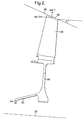
- Fig. 2 shows part of the intermediate pressure compressor 13.
- a rotor blade 26 is shown mounted on a rotor disc 28 connected to a drive arm 30.
- the casing 20 can be seen inclined at an angle ⁇ to the engine centreline 32.
- the drive arm 30 is arranged such that in use, during rotation the rotor disc 28 will move outwards and also forwards due to the moment produced by the centrifugal loads acting at the axial rearward offset 34 of the disc 28.
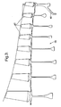
- Fig. 3 shows the principle of Fig. 2 being applied to a multistage compressor drum 38 mounted to a single drive arm 40.
- the drum 38 mounts a plurality of rotor blades 42.
- Fig. 4 shows a further single compressor stage 44 comprising a rotor 46 and a blade 48.
- changes of profile during rotation of the rotor blade 48 itself produces the forward axial movement.
- DelX is produced by the blade 48 alone, whilst delY is produced by the rotor tip and also the disc 46. Respective positions 50 and 52 are shown in Fig. 4a with the rotor at rest and also at speed.
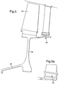
- Fig. 5 shows a further single rotor blade 54 on a disc 56 with a drive arm 58.
- a labyrinth seal 60 is provided at the rear of the rotor arm 56 and the head 62 of the seal 60 is shown in more detail in Fig. 5a illustrating the angle ⁇ .
- delX and delY are taken at the labyrinth seal rather than at the rotor tip.
- Fig. 6 shows an arrangement with a drive arm 64, a rotor blade 66 and a stator 68 behind the blade 66.
- the rotor blade 66 is mounted on a drum 70, and a part 72 thereof extends rearwardly to provide an inclined gap 74 with the stator 68.
- the gap 74 is inclined downwardly forwards with the drive arm cranked forwards, such that rotation of the rotor 70 and hence drive arm 64 causes rearward movement to maintain the gap 74 substantially constant.
- Fig. 7 shows a stator seal mounted on a drive arm 82 which is cranked in a forwards direction (left in the drawings).
- the seal 76 comprises upper and lower plates 84, 86 with a gap therebetween which points downwardly in a forwards direction (left in the drawings) direction.
- a plurality of projections 88 are provided on the plate 86 to enhance the sealing effect.
- Fig. 8 shows part of a modified arrangement similar to Fig. 7 but where a saw tooth profile 90 is provided on an upper plate 92.
- the indentations in the tooth profile correspond to the projections 88 to enhance the sealing effect provided.
- Fig. 9 shows part of a compressor similar to that shown in Fig. 2 except that the casing 94 is inclined outwardly and therefore provides a rising hade angle. Therefore to provide a drive arm 96 which in use will move outwards and rearwards to provide a substantially constant tip clearance for the rotor blade 98, the arm 96 is forward facing relative to the mounting thereof at 100.
- Fig. 10 illustrates a compressor arrangement with an inner wall tip clearance at 102 with a rising hade angle and therefore again a forward facing drive arm 104 is provided.
- Fig. 11 shows a similar inner wall tip clearance in a compressor at 106. However, in this instance there is a falling hade angle, and hence the drive arm 108 is rearward facing.
- Figs. 12 to 15 illustrate different possible arrangements with turbines.
- Fig. 12 shows providing tip clearance at 110 with a falling hade angle.
- the drive arm 112 is rearward facing such that during rotation the turbine blade 114 will move outwards and also forwards due to the moment produced by the centrifugal loads acting at the axial rearward offset mounting 116 of the drive arm 112.
- Fig. 13 shows a similar arrangement to Fig. 12 except that there is a rising hade angle of the casing 118 and therefore a forward facing drive arm 120 is provided.
- Fig. 14 tip clearance is provided at 122 against an inner wall 124 with a rising hade angle.
- a forward facing drive arm 126 is provided so that the wall 124 will move outwards and also rearwards due to the moment produced by centrifugal loads acting in the axial forward offset mounting 128.
- Fig. 15 again shows tip clearance at 130 relative to an inner wall 132. In this instance there is a falling hade angle and therefore there is a rearward facing drive arm 134 to provide outwards and also forwards movement during use.
Landscapes
- Engineering & Computer Science (AREA)
- Mechanical Engineering (AREA)
- General Engineering & Computer Science (AREA)
- Physics & Mathematics (AREA)
- Fluid Mechanics (AREA)
- Structures Of Non-Positive Displacement Pumps (AREA)
- Turbine Rotor Nozzle Sealing (AREA)
- Sealing Using Fluids, Sealing Without Contact, And Removal Of Oil (AREA)
Abstract
Description
Claims (19)
- A spacing arrangement for a gas turbine engine (10), the arrangement comprising a first rotatable member (26, 42, 48, 54, 72, 98, 114) and a second non rotatable member (20, 94, 118) with a gap (34, 74, 102, 106, 110, 122, 130) defined between facing surfaces respectively on the first and second members (26, 42, 48, 54, 72, 98, 114), the gap (34, 74, 102, 106, 110, 122, 130) being inclined relative to the rotational axis (32) of the first member; characterised in that axial movement means (30, 40, 58, 64, 96, 104, 108, 112, 120, 126, 134) are provided which automatically cause relative movement of a one of the first and second members (26, 42, 48, 54, 72, 98, 114) in a direction to tend to increase the gap (34, 74, 102, 106, 110, 122, 130) between the facing surfaces, in response to the rotational speed of the first member (26, 42, 48, 54, 72, 98, 114).
- A spacing arrangement according to claim 1, characterised in that the axial movement means (30, 40, 58, 64, 96, 104, 108, 112, 120, 126, 134) are arranged such that centrifugal forces caused by rotation of the first member (26, 42, 48, 54, 72, 98, 114) cause the axial movement.
- A spacing arrangement according to claim 2, characterised in that the axial movement means is in the form of a connecting member (30, 40, 58, 64, 96, 104, 108, 112, 120, 126, 134) which connects the first member (26, 42, 48, 54, 72, 98, 114) to a source of rotational movement.
- A spacing arrangement according to claim 3, characterised in that the connecting member (30, 40, 58, 64, 96, 104, 108, 112, 120, 126, 134) pivots and/or flexes upon rotational movement to cause the axial movement.
- A spacing arrangement according to any of the preceding claims, characterised in that where there is a falling hade angle, the connecting member (30, 40, 58, 64, 96, 104, 108, 112, 120, 126, 134) extends from the source of rotational movement, in part in a rearwards direction.
- A spacing arrangement according to any of claims 1 to 4, characterised in that where there is a rising hade angle, the connecting member (64, 96, 104, 120, 126) extends from the source of rotational movement, in part in a forwards direction.
- A spacing arrangement according to any of claims 3 to 6, characterised in that a plurality of first members (42) are connected to the connecting member (40).
- A spacing arrangement according to any of the preceding claims, characterised in that the gap (36, 74) is inclined at an angle of between 3 and 30° relative to the rotational axis (32) of the first member (26, 42, 48, 54, 72, 98, 114).
- A spacing arrangement according to any of the preceding claims, characterised in that the first member (26, 42, 48, 54, 72) flexes during rotational movement to cause some or all of the axial movement.
- A spacing arrangement according to any of the preceding claims, characterised in that the arrangement is arranged to provide a substantially constant gap width at all rotational speeds.
- A spacing arrangement according to any of the preceding claims, characterised in that the first member is a compressor blade (26, 42, 48, 54, 66, 98), with the second member a compressor casing (20, 22, 94).
- A compressor (13, 14) for a gas turbine engine (10), characterised in that the compressor (13, 14) comprises one or more spacing arrangements according to any of the preceding claims, provided between the compressor blades (26, 42, 48, 54, 66, 98) and the compressor casing (20, 22, 94).
- A spacing arrangement according to any of claims 1 to 10, characterised in that the first member is a turbine blade (114) and the second member a turbine casing (118).
- A turbine, characterised in that the turbine incorporates a spacing arrangement according to claim 13.
- A spacing arrangement according to any of claims 1 to 10, characterised in that the second member comprises a stator (68) of a compressor (13, 14) or a turbine (16, 17, 18) of a gas turbine engine (10), with the first member being part (72) of the rotor (70).
- A spacing arrangement according to any of claims 1 to 10, characterised in that the spacing arrangement is in the form of a labyrinth seal (60).
- A spacing arrangement according to claim 16, characterised in that one of the facing surfaces (62, 84, 86) is profiled, and the facing surfaces may have complimentary profiles.
- A spacing arrangement according to claim 17, characterised in that one of the facing surfaces (86) includes a plurality of projections.
- A spacing arrangement according to claims 17 or 18, characterised in that one of the facing surfaces has a saw tooth profile.
Applications Claiming Priority (2)
| Application Number | Priority Date | Filing Date | Title |
|---|---|---|---|
| GB0411850 | 2004-05-27 | ||
| GBGB0411850.1A GB0411850D0 (en) | 2004-05-27 | 2004-05-27 | Spacing arrangement |
Publications (3)
| Publication Number | Publication Date |
|---|---|
| EP1600607A2 true EP1600607A2 (en) | 2005-11-30 |
| EP1600607A3 EP1600607A3 (en) | 2013-01-02 |
| EP1600607B1 EP1600607B1 (en) | 2017-03-01 |
Family
ID=32671162
Family Applications (1)
| Application Number | Title | Priority Date | Filing Date |
|---|---|---|---|
| EP05252321.4A Ceased EP1600607B1 (en) | 2004-05-27 | 2005-04-14 | Device to control the radial clearance of the rotor of a gas turbine |
Country Status (4)
| Country | Link |
|---|---|
| US (1) | US7246994B2 (en) |
| EP (1) | EP1600607B1 (en) |
| JP (1) | JP4722553B2 (en) |
| GB (1) | GB0411850D0 (en) |
Cited By (5)
| Publication number | Priority date | Publication date | Assignee | Title |
|---|---|---|---|---|
| EP1918525A2 (en) | 2006-10-16 | 2008-05-07 | United Technologies Corporation | Gas turbine engine seal and corresponding passive sealing clearance control system |
| WO2009074355A1 (en) * | 2007-12-10 | 2009-06-18 | Siemens Aktiengesellschaft | Axial turbo machine having reduced gap leakage |
| WO2013154646A1 (en) | 2012-01-31 | 2013-10-17 | United Technologies Corporation | Compressor flowpath |
| EP2369141A3 (en) * | 2010-03-22 | 2014-09-17 | General Electric Company | Active tip clearance control for shrouded gas turbine blades and related method |
| EP2791475A2 (en) * | 2011-12-15 | 2014-10-22 | Siemens Energy, Inc. | Compressor airfoil tip clearance optimization system |
Families Citing this family (17)
| Publication number | Priority date | Publication date | Assignee | Title |
|---|---|---|---|---|
| US8608424B2 (en) * | 2009-10-09 | 2013-12-17 | General Electric Company | Contoured honeycomb seal for a turbomachine |
| US8777793B2 (en) | 2011-04-27 | 2014-07-15 | United Technologies Corporation | Fan drive planetary gear system integrated carrier and torque frame |
| JP5518022B2 (en) | 2011-09-20 | 2014-06-11 | 三菱重工業株式会社 | Turbine |
| US8863491B2 (en) | 2012-01-31 | 2014-10-21 | United Technologies Corporation | Gas turbine engine shaft bearing configuration |
| US10400629B2 (en) | 2012-01-31 | 2019-09-03 | United Technologies Corporation | Gas turbine engine shaft bearing configuration |
| US8402741B1 (en) | 2012-01-31 | 2013-03-26 | United Technologies Corporation | Gas turbine engine shaft bearing configuration |
| US9038366B2 (en) | 2012-01-31 | 2015-05-26 | United Technologies Corporation | LPC flowpath shape with gas turbine engine shaft bearing configuration |
| US9382807B2 (en) | 2012-05-08 | 2016-07-05 | United Technologies Corporation | Non-axisymmetric rim cavity features to improve sealing efficiencies |
| US10018061B2 (en) | 2013-03-12 | 2018-07-10 | United Technologies Corporation | Vane tip machining fixture assembly |
| WO2015017042A1 (en) * | 2013-07-31 | 2015-02-05 | United Technologies Corporation | Lpc flowpath shape with gas turbine engine shaft bearing configuration |
| US9593589B2 (en) | 2014-02-28 | 2017-03-14 | General Electric Company | System and method for thrust bearing actuation to actively control clearance in a turbo machine |
| US9957826B2 (en) * | 2014-06-09 | 2018-05-01 | United Technologies Corporation | Stiffness controlled abradeable seal system with max phase materials and methods of making same |
| US10036263B2 (en) | 2014-10-22 | 2018-07-31 | United Technologies Corporation | Stator assembly with pad interface for a gas turbine engine |
| GB201912822D0 (en) * | 2019-09-06 | 2019-10-23 | Rolls Royce Plc | Gas turbine engine |
| US11293295B2 (en) | 2019-09-13 | 2022-04-05 | Pratt & Whitney Canada Corp. | Labyrinth seal with angled fins |
| CN112160800B (en) * | 2020-10-16 | 2022-06-14 | 杭州汽轮动力集团有限公司 | Active control device for blade top clearance of axial flow gas turbine |
| CN114251130B (en) * | 2021-12-22 | 2022-12-02 | 清华大学 | Robust rotor structure and power system for controlling blade tip leakage flow |
Family Cites Families (15)
| Publication number | Priority date | Publication date | Assignee | Title |
|---|---|---|---|---|
| JPS57195803A (en) * | 1981-05-27 | 1982-12-01 | Hitachi Ltd | Adjusting device of tip clearance in turbo fluidic machine |
| GB2129880A (en) | 1982-11-09 | 1984-05-23 | Rolls Royce | Gas turbine rotor tip clearance control apparatus |
| US4893983A (en) * | 1988-04-07 | 1990-01-16 | General Electric Company | Clearance control system |
| JPH07109162B2 (en) * | 1988-07-07 | 1995-11-22 | ユニオン・カーバイド・コーポレーション | Wear resistance and grindability for rotary labyrinth seal members Laser engraving Ceramic or metal carbide surface |
| JPH09264101A (en) * | 1996-03-28 | 1997-10-07 | Mitsubishi Heavy Ind Ltd | Moving blade structure for steam turbine |
| WO1999028598A1 (en) | 1997-12-02 | 1999-06-10 | Siemens Aktiengesellschaft | Turbomachine and method for adjusting the width of a radial gap |
| JP2000018003A (en) * | 1998-06-30 | 2000-01-18 | Toshiba Corp | Turbine blade |
| US6511294B1 (en) * | 1999-09-23 | 2003-01-28 | General Electric Company | Reduced-stress compressor blisk flowpath |
| US6227794B1 (en) * | 1999-12-16 | 2001-05-08 | Pratt & Whitney Canada Corp. | Fan case with flexible conical ring |
| US6439842B1 (en) * | 2000-03-29 | 2002-08-27 | General Electric Company | Gas turbine engine stator case |
| DE10060740A1 (en) | 2000-12-07 | 2002-06-13 | Alstom Switzerland Ltd | Device for setting gap dimensions for a turbomachine |
| JP2002213204A (en) * | 2001-01-15 | 2002-07-31 | Toshiba Corp | Turbine blade and turbine |
| EP1243756A1 (en) * | 2001-03-23 | 2002-09-25 | Siemens Aktiengesellschaft | Turbine |
| GB2374123B (en) * | 2001-04-05 | 2004-09-08 | Rolls Royce Plc | Gas turbine engine system |
| DE50112597D1 (en) * | 2001-04-12 | 2007-07-19 | Siemens Ag | Gas turbine with axially movable housing parts |
-
2004
- 2004-05-27 GB GBGB0411850.1A patent/GB0411850D0/en not_active Ceased
-
2005
- 2005-04-14 EP EP05252321.4A patent/EP1600607B1/en not_active Ceased
- 2005-04-15 US US11/106,621 patent/US7246994B2/en not_active Expired - Lifetime
- 2005-05-20 JP JP2005148066A patent/JP4722553B2/en not_active Expired - Lifetime
Cited By (8)
| Publication number | Priority date | Publication date | Assignee | Title |
|---|---|---|---|---|
| EP1918525A2 (en) | 2006-10-16 | 2008-05-07 | United Technologies Corporation | Gas turbine engine seal and corresponding passive sealing clearance control system |
| EP1918525A3 (en) * | 2006-10-16 | 2010-10-06 | United Technologies Corporation | Gas turbine engine seal and corresponding passive sealing clearance control system |
| WO2009074355A1 (en) * | 2007-12-10 | 2009-06-18 | Siemens Aktiengesellschaft | Axial turbo machine having reduced gap leakage |
| EP2369141A3 (en) * | 2010-03-22 | 2014-09-17 | General Electric Company | Active tip clearance control for shrouded gas turbine blades and related method |
| US8939715B2 (en) | 2010-03-22 | 2015-01-27 | General Electric Company | Active tip clearance control for shrouded gas turbine blades and related method |
| EP2791475A2 (en) * | 2011-12-15 | 2014-10-22 | Siemens Energy, Inc. | Compressor airfoil tip clearance optimization system |
| WO2013154646A1 (en) | 2012-01-31 | 2013-10-17 | United Technologies Corporation | Compressor flowpath |
| EP2809935A4 (en) * | 2012-01-31 | 2015-08-26 | United Technologies Corp | Compressor flowpath |
Also Published As
| Publication number | Publication date |
|---|---|
| JP4722553B2 (en) | 2011-07-13 |
| US20050265825A1 (en) | 2005-12-01 |
| EP1600607A3 (en) | 2013-01-02 |
| GB0411850D0 (en) | 2004-06-30 |
| JP2005337248A (en) | 2005-12-08 |
| US7246994B2 (en) | 2007-07-24 |
| EP1600607B1 (en) | 2017-03-01 |
Similar Documents
| Publication | Publication Date | Title |
|---|---|---|
| US7246994B2 (en) | Spacing arrangement | |
| US11560851B2 (en) | Geared turbofan engine with high compressor exit temperature | |
| US8282346B2 (en) | Methods, systems and/or apparatus relating to seals for turbine engines | |
| US8317465B2 (en) | Systems and apparatus relating to turbine engines and seals for turbine engines | |
| US7207776B2 (en) | Cooling arrangement | |
| US20140260326A1 (en) | Geared turbofan engine with high compressor exit temperature | |
| JP6145296B2 (en) | Turbomachine blade tip shroud with parallel casing configuration | |
| US8371816B2 (en) | Rotor blades for turbine engines | |
| US7241109B2 (en) | Seal system | |
| US8312729B2 (en) | Flow discouraging systems and gas turbine engines | |
| JPH04228836A (en) | Inter-stage seal structure used for air wheel stage of turbine engine double reversing rotor | |
| EP2978938A1 (en) | Rotor blade with l-shaped feather seal | |
| US10100648B2 (en) | Damper seal installation features | |
| GB2434842A (en) | Cooling arrangement for a turbine blade shroud | |
| CA2923326C (en) | Geared turbofan engine with high compressor exit temperature | |
| US20200011188A1 (en) | Blade for a gas turbine engine | |
| US11512602B2 (en) | Seal element for sealing a joint between a rotor blade and a rotor disk | |
| US12352175B2 (en) | Annulus filler for a gas turbine engine | |
| WO2011145326A1 (en) | Turbine of gas turbine engine | |
| GB2543327A (en) | Aerofoil tip profiles |
Legal Events
| Date | Code | Title | Description |
|---|---|---|---|
| PUAI | Public reference made under article 153(3) epc to a published international application that has entered the european phase |
Free format text: ORIGINAL CODE: 0009012 |
|
| AK | Designated contracting states |
Kind code of ref document: A2 Designated state(s): AT BE BG CH CY CZ DE DK EE ES FI FR GB GR HU IE IS IT LI LT LU MC NL PL PT RO SE SI SK TR |
|
| AX | Request for extension of the european patent |
Extension state: AL BA HR LV MK YU |
|
| PUAL | Search report despatched |
Free format text: ORIGINAL CODE: 0009013 |
|
| AK | Designated contracting states |
Kind code of ref document: A3 Designated state(s): AT BE BG CH CY CZ DE DK EE ES FI FR GB GR HU IE IS IT LI LT LU MC NL PL PT RO SE SI SK TR |
|
| AX | Request for extension of the european patent |
Extension state: AL BA HR LV MK YU |
|
| RIC1 | Information provided on ipc code assigned before grant |
Ipc: F01D 11/20 20060101AFI20121126BHEP |
|
| 17P | Request for examination filed |
Effective date: 20130702 |
|
| RBV | Designated contracting states (corrected) |
Designated state(s): AT BE BG CH CY CZ DE DK EE ES FI FR GB GR HU IE IS IT LI LT LU MC NL PL PT RO SE SI SK TR |
|
| AKX | Designation fees paid |
Designated state(s): DE FR GB |
|
| RAP1 | Party data changed (applicant data changed or rights of an application transferred) |
Owner name: ROLLS-ROYCE PLC |
|
| 17Q | First examination report despatched |
Effective date: 20160510 |
|
| GRAP | Despatch of communication of intention to grant a patent |
Free format text: ORIGINAL CODE: EPIDOSNIGR1 |
|
| STAA | Information on the status of an ep patent application or granted ep patent |
Free format text: STATUS: GRANT OF PATENT IS INTENDED |
|
| INTG | Intention to grant announced |
Effective date: 20161110 |
|
| GRAS | Grant fee paid |
Free format text: ORIGINAL CODE: EPIDOSNIGR3 |
|
| GRAA | (expected) grant |
Free format text: ORIGINAL CODE: 0009210 |
|
| STAA | Information on the status of an ep patent application or granted ep patent |
Free format text: STATUS: THE PATENT HAS BEEN GRANTED |
|
| AK | Designated contracting states |
Kind code of ref document: B1 Designated state(s): DE FR GB |
|
| REG | Reference to a national code |
Ref country code: GB Ref legal event code: FG4D |
|
| REG | Reference to a national code |
Ref country code: DE Ref legal event code: R096 Ref document number: 602005051396 Country of ref document: DE |
|
| REG | Reference to a national code |
Ref country code: FR Ref legal event code: PLFP Year of fee payment: 13 |
|
| REG | Reference to a national code |
Ref country code: DE Ref legal event code: R097 Ref document number: 602005051396 Country of ref document: DE |
|
| PLBE | No opposition filed within time limit |
Free format text: ORIGINAL CODE: 0009261 |
|
| STAA | Information on the status of an ep patent application or granted ep patent |
Free format text: STATUS: NO OPPOSITION FILED WITHIN TIME LIMIT |
|
| 26N | No opposition filed |
Effective date: 20171204 |
|
| REG | Reference to a national code |
Ref country code: FR Ref legal event code: PLFP Year of fee payment: 14 |
|
| PGFP | Annual fee paid to national office [announced via postgrant information from national office to epo] |
Ref country code: DE Payment date: 20190429 Year of fee payment: 15 |
|
| PGFP | Annual fee paid to national office [announced via postgrant information from national office to epo] |
Ref country code: FR Payment date: 20190425 Year of fee payment: 15 |
|
| PGFP | Annual fee paid to national office [announced via postgrant information from national office to epo] |
Ref country code: GB Payment date: 20190429 Year of fee payment: 15 |
|
| REG | Reference to a national code |
Ref country code: DE Ref legal event code: R119 Ref document number: 602005051396 Country of ref document: DE |
|
| PG25 | Lapsed in a contracting state [announced via postgrant information from national office to epo] |
Ref country code: DE Free format text: LAPSE BECAUSE OF NON-PAYMENT OF DUE FEES Effective date: 20201103 Ref country code: FR Free format text: LAPSE BECAUSE OF NON-PAYMENT OF DUE FEES Effective date: 20200430 |
|
| GBPC | Gb: european patent ceased through non-payment of renewal fee |
Effective date: 20200414 |
|
| PG25 | Lapsed in a contracting state [announced via postgrant information from national office to epo] |
Ref country code: GB Free format text: LAPSE BECAUSE OF NON-PAYMENT OF DUE FEES Effective date: 20200414 |