EP1600262A1 - Multiple container - Google Patents
Multiple container Download PDFInfo
- Publication number
- EP1600262A1 EP1600262A1 EP05011083A EP05011083A EP1600262A1 EP 1600262 A1 EP1600262 A1 EP 1600262A1 EP 05011083 A EP05011083 A EP 05011083A EP 05011083 A EP05011083 A EP 05011083A EP 1600262 A1 EP1600262 A1 EP 1600262A1
- Authority
- EP
- European Patent Office
- Prior art keywords
- container according
- multiple container
- trays
- another
- connection structure
- Prior art date
- Legal status (The legal status is an assumption and is not a legal conclusion. Google has not performed a legal analysis and makes no representation as to the accuracy of the status listed.)
- Withdrawn
Links
Images



Classifications
-
- A—HUMAN NECESSITIES
- A47—FURNITURE; DOMESTIC ARTICLES OR APPLIANCES; COFFEE MILLS; SPICE MILLS; SUCTION CLEANERS IN GENERAL
- A47F—SPECIAL FURNITURE, FITTINGS, OR ACCESSORIES FOR SHOPS, STOREHOUSES, BARS, RESTAURANTS OR THE LIKE; PAYING COUNTERS
- A47F5/00—Show stands, hangers, or shelves characterised by their constructional features
- A47F5/10—Adjustable or foldable or dismountable display stands
-
- A—HUMAN NECESSITIES
- A47—FURNITURE; DOMESTIC ARTICLES OR APPLIANCES; COFFEE MILLS; SPICE MILLS; SUCTION CLEANERS IN GENERAL
- A47F—SPECIAL FURNITURE, FITTINGS, OR ACCESSORIES FOR SHOPS, STOREHOUSES, BARS, RESTAURANTS OR THE LIKE; PAYING COUNTERS
- A47F5/00—Show stands, hangers, or shelves characterised by their constructional features
- A47F5/0043—Show shelves
- A47F5/005—Partitions therefore
- A47F5/0062—Terraced platforms on shelves or trays
-
- B—PERFORMING OPERATIONS; TRANSPORTING
- B25—HAND TOOLS; PORTABLE POWER-DRIVEN TOOLS; MANIPULATORS
- B25H—WORKSHOP EQUIPMENT, e.g. FOR MARKING-OUT WORK; STORAGE MEANS FOR WORKSHOPS
- B25H3/00—Storage means or arrangements for workshops facilitating access to, or handling of, work tools or instruments
- B25H3/02—Boxes
- B25H3/021—Boxes comprising a number of connected storage elements
- B25H3/023—Boxes comprising a number of connected storage elements movable relative to one another for access to their interiors
- B25H3/025—Boxes comprising a number of connected storage elements movable relative to one another for access to their interiors by rotation about a common axis
-
- B—PERFORMING OPERATIONS; TRANSPORTING
- B25—HAND TOOLS; PORTABLE POWER-DRIVEN TOOLS; MANIPULATORS
- B25H—WORKSHOP EQUIPMENT, e.g. FOR MARKING-OUT WORK; STORAGE MEANS FOR WORKSHOPS
- B25H3/00—Storage means or arrangements for workshops facilitating access to, or handling of, work tools or instruments
- B25H3/02—Boxes
- B25H3/021—Boxes comprising a number of connected storage elements
- B25H3/023—Boxes comprising a number of connected storage elements movable relative to one another for access to their interiors
- B25H3/027—Boxes comprising a number of connected storage elements movable relative to one another for access to their interiors by sliding along one another
-
- B—PERFORMING OPERATIONS; TRANSPORTING
- B65—CONVEYING; PACKING; STORING; HANDLING THIN OR FILAMENTARY MATERIAL
- B65D—CONTAINERS FOR STORAGE OR TRANSPORT OF ARTICLES OR MATERIALS, e.g. BAGS, BARRELS, BOTTLES, BOXES, CANS, CARTONS, CRATES, DRUMS, JARS, TANKS, HOPPERS, FORWARDING CONTAINERS; ACCESSORIES, CLOSURES, OR FITTINGS THEREFOR; PACKAGING ELEMENTS; PACKAGES
- B65D11/00—Containers having bodies formed by interconnecting or uniting two or more rigid, or substantially rigid, components made wholly or mainly of plastics material
-
- B—PERFORMING OPERATIONS; TRANSPORTING
- B65—CONVEYING; PACKING; STORING; HANDLING THIN OR FILAMENTARY MATERIAL
- B65D—CONTAINERS FOR STORAGE OR TRANSPORT OF ARTICLES OR MATERIALS, e.g. BAGS, BARRELS, BOTTLES, BOXES, CANS, CARTONS, CRATES, DRUMS, JARS, TANKS, HOPPERS, FORWARDING CONTAINERS; ACCESSORIES, CLOSURES, OR FITTINGS THEREFOR; PACKAGING ELEMENTS; PACKAGES
- B65D25/00—Details of other kinds or types of rigid or semi-rigid containers
- B65D25/02—Internal fittings
- B65D25/04—Partitions
-
- A—HUMAN NECESSITIES
- A45—HAND OR TRAVELLING ARTICLES
- A45C—PURSES; LUGGAGE; HAND CARRIED BAGS
- A45C11/00—Receptacles for purposes not provided for in groups A45C1/00-A45C9/00
- A45C11/16—Jewel boxes
-
- A—HUMAN NECESSITIES
- A45—HAND OR TRAVELLING ARTICLES
- A45D—HAIRDRESSING OR SHAVING EQUIPMENT; EQUIPMENT FOR COSMETICS OR COSMETIC TREATMENTS, e.g. FOR MANICURING OR PEDICURING
- A45D33/00—Containers or accessories specially adapted for handling powdery toiletry or cosmetic substances
- A45D33/20—Containers with movably mounted drawers
Definitions
- the subject of the present invention is a multiple container (for example for confectionery products, such as chocolates and pralines, or else any other product to be divided into compartments such as articles for cosmetics, and the like), having a peculiar configuration that is relatively complex from the structural standpoint, but at the same time may be produced at extremely contained costs.
- the multiple container according to the invention is basically characterized in that it comprises a plurality of distinct containers joined to one another and to a common connection structure, which enables reciprocal angular displacements thereof between a position in which they are set alongside one another and a position in which they are spaced at a distance from one another.
- the containers can be variously connected to each other, for example by means of slots or simply by means of flexible joining elements (for example, strips of adhesive tape) that enable mutual articulation thereof.
- the containers are formed in a single piece of plastic material integrally moulded with the common connection structure.
- the individual containers of the multiple container are conveniently formed by trays, which, in a preferred embodiment of the invention, have a polygonal shape.
- the common connection structure consists of a wall formed by a series of sections mutually articulated to one another and joined, at progressively differing levels, each to at least one side of a respective tray.
- Said wall may be configured, starting from a closed condition, in which it delimits peripherally the container constituting the side wall thereof and said trays are set on top of one another, in an open configuration, in which the trays are laterally staggered with respect to one another.
- the trays have a circular-sector configuration
- the connection structure consists of arms radially arranged in spokelike fashion, connected in an articulated way to the free end of each of which is an end edge ???of a respective tray having the shape of a circular sector.
- Said trays are displaceable, from a condition closed against the spokelike radial arrangement, to an open position on the outside of said spokelike arrangement.
- the container according to the invention can conveniently be produced in a relatively simple and low-cost way in a single piece, by means of injection moulding of suitable plastic materials.
- the container is in fact without any undercuts that could complicate the moulding operation, and the articulation parts present therein can be conveniently formed like flexible hinges constituted by areas of thinned plastic material. This enables convenient moulding of the container in a opened-out configuration, i.e., in the mutually separated position in the case of trays having a polygonal shape and in the open position in the case of trays having the shape of a circular sector.
- number 1 designates as a whole a multiple container according to a first embodiment of the invention.
- the multiple container 1 has, in the case of the example illustrated, a general prismatic shape with a regular hexagonal base, defined by a column of containers 2a, 2b, 2c, 2d, 2e set on top of one another in the form of trays, which are hexagonal in plan view and open at the top.
- both the number and the shape of the trays 2 may vary widely with respect to the case of the example illustrated, in which they number five and, as has been said, have a hexagonal shape.
- said shape could be any polygon, from a quadrilateral to an octagon or decagon.
- the shape will be identical for all the trays 2a-2e, whilst their depth may possibly be differentiated according to the different products (for example, chocolates, pralines and the like) which are to be put therein.
- the top tray 2a has a depth greater than that of the others, whilst the intermediate tray 2d has a smaller depth than that of the others.
- each tray 2a-2e is closed at the top by the bottom of the overlying tray, except, of course, the top tray 2a, which may be in turn closed by a separate lid or else, possibly, an integral lid.
- the trays 2 are formed integrally with respect to one another, i.e., they are made of a single piece, by means of injection moulding of plastic material.
- plastic material used will be conveniently polypropylene of the "random" type, or else SBS (styrene-butadiene-styrene), or the like.
- the trays 2a-2e are rendered integral with respect to one another thanks to the presence of a common connection structure that joins them.
- said common structure is constituted by a vertical side wall 3, which, in the closed condition of the container 1 represented in Figure 1, delimits it peripherally.
- the wall 3 is formed by a series of sections 3a-3f of equal number (or, as in the case of the example illustrated, one more than the number of trays 2a-2e), articulated to one another via hinges 4, which are constituted by thinned-out integral portions of the wall 3 itself and are formed by moulding.
- Each of the trays 2a-2e is joined along one side thereof to a respective section 3a-3e and 3f of the wall 3, at a level progressively increasing from the lowest tray 2e to the top tray 2a.
- the difference in level between each tray and the tray on top of it will be slightly greater than the depth of the tray underneath.
- the section 3f is joined to a second side of the top tray 3f, adjacent to its side of joining with the section 3a.
- An integral lid may be articulated, via a flexible hinge similar to the hinges 4, to said section 3f.
- a separate lid may be provided.
- each tray 2a-2e and the respective section 3a-3e and 3f of the wall 3 is materially present, it should be pointed out that said side could, instead, be absent and formed by the corresponding section 3a-3e and 3f itself.
- an openable closing lid could be joined in an articulated way, via a flexible hinge similar to the flexible hinges 4, to one of the sides of the top tray 2a.
- plastic materials indicated above for the injection moulding of the container 1 are particularly suitable for ensuring the necessary elasticity and the necessary resistance to fatigue of the flexible hinges 4. However, other plastic materials different from the ones indicated may be considered as suitable.
- the flexible hinges 4 can possibly be reinforced, for example, via application thereon of adhesive tape made of paper or plastic material (not illustrated).
- the container 1 can be opened out, starting from the closed configuration of Figure 1, to a condition of partial opening represented in Figure 2, up to a condition of complete opening represented in Figure 3. To do this, it is sufficient to rotate the trays 2a-2e with respect to one another about the flexible hinges 4 of the wall 3, together with the sections 3a-3e and 3f thereof.
- the trays 2a-2e are arranged increasingly staggered laterally with respect to one another, thus rendering their contents immediately accessible.
- the shape and number of the trays of the container 1 may vary widely with respect to the case of the example described so far herein.
- said trays and the corresponding common connection structure may also be such that, in the closed condition of the container, the trays are adjacent to or set alongside one another on one and the same plane, instead of being set on top of one another.
- the container designated as a whole by 10
- the container has a connection structure constituted by a spokelike radial arrangement 13 formed by three arms 13a, 13b and 13c angularly at the same distance apart from one another.
- the container 10 is completed by a lid constituted by a plate 15 having a circular shape, joined to the arms 13a-13c of the spokelike radial arrangement structure 13 above the trays 12a-12c.
- the trays 12a-12c are displaceable, starting from the closed condition shown in Figure 5, to a condition of partial opening represented in Figure 6, and further to a condition of total opening by rotation of said trays about the axes of the flexible hinges 14.
- the trays 12a-12c are positioned against the arms 13a-13c of the spokelike structure 13, so that the container 10 has a general cylindrical configuration with circular cross section. Rotation of the trays 12a-12c with respect to the spokelike structure 13 evidently makes it possible to obtain a mutual separation outwards, beyond the lid 15, so as to enable access to the products contained therein.
- the container 10 can be made of a single piece by injection moulding of a plastic material such as "random" propylene, SBS and the like.
- the container 10 of Figures 5-7 may be completed by a base having a shape identical to that of the lid 15, joined to the spokelike structure 13 underneath the trays 12a-12c.
- the trays 12a-12c will rotate with respect to the arms 13a-13c within the gap comprised between the lid 15 and the base.
- this solution albeit structurally more complete, entails problems of moulding unlike that described with reference to Figures 5 to 7 on account of the presence of the undercut constituted by the base plate.
- the container may be usefully employed in the home for collecting different objects, such as, for example, articles of make-up, implements and yarn for sewing, small toys, etc.
- the connected containers can be joined to one another and to the common connection structure variously, for example by means of slots or simply by means of flexible joining elements (for instance, strips of adhesive tape) that enable mutual articulation thereof.
- the preferred embodiment in which the containers are formed in a single piece of plastic material integrally moulded to the common connection structure is extremely advantageous on account of its simplicity of fabrication.
Landscapes
- Engineering & Computer Science (AREA)
- Mechanical Engineering (AREA)
- Containers Having Bodies Formed In One Piece (AREA)
Abstract
Described herein is a multiple container (1), for
example for confectionery products and the like,
comprising a plurality of distinct containers (2a-2e)
formed in a single piece of plastic material integrally
moulded with a common connection structure (3) that
enables mutual angular displacements thereof between a
position in which they are set alongside one another
and a position in which they are separated from one
another.
Description
- The subject of the present invention is a multiple container (for example for confectionery products, such as chocolates and pralines, or else any other product to be divided into compartments such as articles for cosmetics, and the like), having a peculiar configuration that is relatively complex from the structural standpoint, but at the same time may be produced at extremely contained costs.
- The multiple container according to the invention is basically characterized in that it comprises a plurality of distinct containers joined to one another and to a common connection structure, which enables reciprocal angular displacements thereof between a position in which they are set alongside one another and a position in which they are spaced at a distance from one another.
- The containers can be variously connected to each other, for example by means of slots or simply by means of flexible joining elements (for example, strips of adhesive tape) that enable mutual articulation thereof. However, according to a preferred embodiment of the invention, the containers are formed in a single piece of plastic material integrally moulded with the common connection structure.
- The individual containers of the multiple container are conveniently formed by trays, which, in a preferred embodiment of the invention, have a polygonal shape. In this case, the common connection structure consists of a wall formed by a series of sections mutually articulated to one another and joined, at progressively differing levels, each to at least one side of a respective tray. Said wall may be configured, starting from a closed condition, in which it delimits peripherally the container constituting the side wall thereof and said trays are set on top of one another, in an open configuration, in which the trays are laterally staggered with respect to one another.
- In a variant of the invention, the trays have a circular-sector configuration, and the connection structure consists of arms radially arranged in spokelike fashion, connected in an articulated way to the free end of each of which is an end edge ???of a respective tray having the shape of a circular sector. Said trays are displaceable, from a condition closed against the spokelike radial arrangement, to an open position on the outside of said spokelike arrangement.
- In both of the aforesaid embodiments, as well as in possible variants that, albeit in different forms, reproduce the same innovative concept, the container according to the invention can conveniently be produced in a relatively simple and low-cost way in a single piece, by means of injection moulding of suitable plastic materials. The container is in fact without any undercuts that could complicate the moulding operation, and the articulation parts present therein can be conveniently formed like flexible hinges constituted by areas of thinned plastic material. This enables convenient moulding of the container in a opened-out configuration, i.e., in the mutually separated position in the case of trays having a polygonal shape and in the open position in the case of trays having the shape of a circular sector.
- The invention will now be described in detail with reference to the annexed plate of drawings, which are provided purely by of way of non-limiting example and in which:
- Figure 1 is a schematic perspective top view of a multiple container according to a first embodiment of the invention, represented in a closed configuration;
- Figure 2 is a view similar to that of Figure 1, which shows the container in a partially opened position;
- Figure 3 is a view similar to that of Figures 1 and 2, which shows the container in a completely opened position;
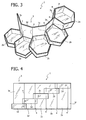
- Figure 4 is a front elevation of the container of Figure 3;
- Figure 5 is a schematic perspective top view of a second embodiment of the container according to the invention, represented in a closed condition;
- Figure 6 is a view similar to that of Figure 5, which shows the container in a partially opened condition; and
- Figure 7 is a partial cross-sectional view at an enlarged scale of the detail indicated by the arrow 6 in Figure 6.
-
- With initial reference to Figures 1 to 4,
number 1 designates as a whole a multiple container according to a first embodiment of the invention. In the closed configuration represented in Figure 1, themultiple container 1 has, in the case of the example illustrated, a general prismatic shape with a regular hexagonal base, defined by a column ofcontainers - It should at once be pointed out that both the number and the shape of the trays 2 may vary widely with respect to the case of the example illustrated, in which they number five and, as has been said, have a hexagonal shape.
- Thus, said shape could be any polygon, from a quadrilateral to an octagon or decagon. In general, the shape will be identical for all the
trays 2a-2e, whilst their depth may possibly be differentiated according to the different products (for example, chocolates, pralines and the like) which are to be put therein. Thus, in the case of the example illustrated in Figures 1 to 3, thetop tray 2a has a depth greater than that of the others, whilst theintermediate tray 2d has a smaller depth than that of the others. - In the closed condition of Figure 1, each
tray 2a-2e is closed at the top by the bottom of the overlying tray, except, of course, thetop tray 2a, which may be in turn closed by a separate lid or else, possibly, an integral lid. - The trays 2 are formed integrally with respect to one another, i.e., they are made of a single piece, by means of injection moulding of plastic material. For the reasons that will also be clarified in what follows, the plastic material used will be conveniently polypropylene of the "random" type, or else SBS (styrene-butadiene-styrene), or the like.
- The
trays 2a-2e are rendered integral with respect to one another thanks to the presence of a common connection structure that joins them. In the case of the embodiment of Figures 1 to 4, said common structure is constituted by avertical side wall 3, which, in the closed condition of thecontainer 1 represented in Figure 1, delimits it peripherally. Thewall 3 is formed by a series ofsections 3a-3f of equal number (or, as in the case of the example illustrated, one more than the number oftrays 2a-2e), articulated to one another viahinges 4, which are constituted by thinned-out integral portions of thewall 3 itself and are formed by moulding. - Each of the
trays 2a-2e is joined along one side thereof to arespective section 3a-3e and 3f of thewall 3, at a level progressively increasing from thelowest tray 2e to thetop tray 2a. The difference in level between each tray and the tray on top of it will be slightly greater than the depth of the tray underneath. - The
section 3f is joined to a second side of thetop tray 3f, adjacent to its side of joining with thesection 3a. An integral lid may be articulated, via a flexible hinge similar to thehinges 4, to saidsection 3f. Alternatively, a separate lid may be provided. - Although, in the example illustrated, the side of joining between each
tray 2a-2e and therespective section 3a-3e and 3f of thewall 3 is materially present, it should be pointed out that said side could, instead, be absent and formed by thecorresponding section 3a-3e and 3f itself. - Furthermore, an openable closing lid could be joined in an articulated way, via a flexible hinge similar to the
flexible hinges 4, to one of the sides of thetop tray 2a. - The plastic materials indicated above for the injection moulding of the
container 1 are particularly suitable for ensuring the necessary elasticity and the necessary resistance to fatigue of theflexible hinges 4. However, other plastic materials different from the ones indicated may be considered as suitable. - In order to ensure a longer durability and resistance to repeated rotations, the
flexible hinges 4 can possibly be reinforced, for example, via application thereon of adhesive tape made of paper or plastic material (not illustrated). - With the arrangement described above, the
container 1 can be opened out, starting from the closed configuration of Figure 1, to a condition of partial opening represented in Figure 2, up to a condition of complete opening represented in Figure 3. To do this, it is sufficient to rotate thetrays 2a-2e with respect to one another about theflexible hinges 4 of thewall 3, together with thesections 3a-3e and 3f thereof. - In this way, the
trays 2a-2e are arranged increasingly staggered laterally with respect to one another, thus rendering their contents immediately accessible. - In order to bring the
container 1 into the closed starting position, it is sufficient to rotate thetrays 2a-2e with thecorresponding sections 3a-3e and 3f in an opposite direction until the closed perimeter of thewall 3 is restored. - The configuration of Figure 3, or even a still more open configuration in which there is no substantial overlapping between the
trays 2a-2e, corresponds to the opened-out configuration in which themultiple container 1 is formed by means of injection moulding. Since no undercut of any sort is present in said configuration, the forming mould may be particularly simple and without mobile parts such as carriages and other solutions that are instead notoriously necessary for forming items with undercuts. - As has already been clarified previously, the shape and number of the trays of the
container 1 may vary widely with respect to the case of the example described so far herein. In addition, said trays and the corresponding common connection structure may also be such that, in the closed condition of the container, the trays are adjacent to or set alongside one another on one and the same plane, instead of being set on top of one another. - Such a configuration is represented in the variant of Figures 5 to 7. In this variant, the container, designated as a whole by 10, has a connection structure constituted by a spokelike
radial arrangement 13 formed by threearms arm 13a-13c, in the way clarified in what follows, is arespective tray 12a-12c having the shape in plan view of a circular sector of an amplitude corresponding to the angular interval between thearms 13a-13c (i.e., 120°). - The detail of the articulation between each tray and the corresponding arm of the
structure 13 is illustrated in Figure 7, with expressed reference to thetray 12c: an integralflexible hinge 14 is provided between the free end of thearm 13c and the corresponding sharp edge of thetray 12c comprised between the curved side and the corresponding radial rectilinear side thereof. - The
container 10 is completed by a lid constituted by aplate 15 having a circular shape, joined to thearms 13a-13c of the spokelikeradial arrangement structure 13 above thetrays 12a-12c. - With this arrangement, the
trays 12a-12c are displaceable, starting from the closed condition shown in Figure 5, to a condition of partial opening represented in Figure 6, and further to a condition of total opening by rotation of said trays about the axes of theflexible hinges 14. In the closed position illustrated in Figure 5, thetrays 12a-12c are positioned against thearms 13a-13c of thespokelike structure 13, so that thecontainer 10 has a general cylindrical configuration with circular cross section. Rotation of thetrays 12a-12c with respect to thespokelike structure 13 evidently makes it possible to obtain a mutual separation outwards, beyond thelid 15, so as to enable access to the products contained therein. - Also in this case, the
container 10 can be made of a single piece by injection moulding of a plastic material such as "random" propylene, SBS and the like. - In a possible further variant, not illustrated in the drawings, the
container 10 of Figures 5-7 may be completed by a base having a shape identical to that of thelid 15, joined to thespokelike structure 13 underneath thetrays 12a-12c. In this case, thetrays 12a-12c will rotate with respect to thearms 13a-13c within the gap comprised between thelid 15 and the base. However, this solution, albeit structurally more complete, entails problems of moulding unlike that described with reference to Figures 5 to 7 on account of the presence of the undercut constituted by the base plate. - Also the variant of Figures 5 to 7 may undergo numerous modifications, in particular as regards the number and conformation of the
trays 12a-12c. - From the foregoing description, it will appear evident that the peculiar conformation of the multiple container according to the invention enables, with extremely limited production costs, new and original shapes to be obtained that can contribute to a greater commercial success of the products packaged therein. This is particularly true in the case where the material for injection moulding of the container is transparent so as to render the products therein immediately visible to the public.
- Finally, it should be pointed out that, once its original contents are used up, the container may be usefully employed in the home for collecting different objects, such as, for example, articles of make-up, implements and yarn for sewing, small toys, etc.
- Of course, the details of construction and the embodiments may vary widely with respect to what is described and illustrated herein, without thereby departing from the scope of the present invention as defined in the ensuing claims. Thus, the connected containers can be joined to one another and to the common connection structure variously, for example by means of slots or simply by means of flexible joining elements (for instance, strips of adhesive tape) that enable mutual articulation thereof. However, the preferred embodiment in which the containers are formed in a single piece of plastic material integrally moulded to the common connection structure is extremely advantageous on account of its simplicity of fabrication.
Claims (15)
- A multiple container (1; 10), characterized in that it comprises a plurality of distinct containers (2a-2e; 12a-12c) made of moulded plastic material, joined to one another and to a common connection structure (3; 13) that enables angular displacements thereof between a position in which they are set alongside one another and a position in which they are spaced at a distance from one another.
- The multiple container according to Claim 1, characterized in that said containers (2a-2e; 12a-12c) and said common connection structure (3; 13) are formed in a single piece by moulding.
- The multiple container according to Claim 1 or Claim 2, characterized in that said containers are formed by trays (2a-2e; 12a-12c).
- The multiple container according to Claim 3, characterized in that said trays (2a-2e) have a polygonal shape.
- The multiple container according to Claim 1 or Claim 2, characterized in that said common connection structure consists in a wall (3) formed by a series of sections (3a-3e) mutually articulated to one another and joined, at progressively different levels, each to at least one side of a respective tray (2a-2e); said wall (3) being configurable, starting from a closed condition, in which it delimits peripherally the container (1) constituting the side wall thereof and said trays (2a-2e) are set on top of one another, in an open configuration, in which said trays (2a-2e) are laterally staggered with respect to one another.
- The multiple container according to Claim 5, characterized in that said sections (3a-3e) of said wall (3) are articulated with respect to one another via integral flexible hinges (4).
- The multiple container according to Claim 6, characterized in that said integral hinges (4) are provided with strengthening means.
- The multiple container according to Claim 3, characterized in that said trays (12a-12c) have a circular-sector configuration.
- The multiple container according to Claim 8, characterized in that said connection structure consists in a spokelike radial arrangement (13) of arms (13a-13c) to the free end of each of which there is connected in an articulated way an end edge of a respective tray having the shape of a circular sector (12a-12c); said trays (12a-12c) being displaceable, starting from a condition closed against said spokelike radial arrangement (13), to an opened position on the outside of said spokelike arrangement (13).
- The multiple container according to Claim 9, characterized in that said spokelike radial arrangement (13) includes at least three arms (13a-13c) angularly at the same distance apart from one another, so that said trays (12a-12c) number at least three.
- The multiple container according to Claim 9, characterized in that said trays (12a-12c) are articulated to said arms (13a-13c) via integral flexible hinges (14).
- The multiple container according to Claim 11, characterized in that said integral hinges (14) are provided with strengthening means.
- The multiple container according to one or more of the preceding claims, characterized in that it further includes a lid (15).
- The multiple container according to Claim 13, characterized in that said lid (15) is formed integrally with said connection structure (13).
- The multiple container according to one or more of the preceding claims, characterized in that it is moulded in said position in which said individual containers are set at a distance from one another.
Applications Claiming Priority (2)
| Application Number | Priority Date | Filing Date | Title |
|---|---|---|---|
| ITTO20040363 ITTO20040363A1 (en) | 2004-05-28 | 2004-05-28 | MULTIPLE CONTAINER. |
| ITTO20040363 | 2004-05-28 |
Publications (1)
| Publication Number | Publication Date |
|---|---|
| EP1600262A1 true EP1600262A1 (en) | 2005-11-30 |
Family
ID=34977037
Family Applications (1)
| Application Number | Title | Priority Date | Filing Date |
|---|---|---|---|
| EP05011083A Withdrawn EP1600262A1 (en) | 2004-05-28 | 2005-05-23 | Multiple container |
Country Status (2)
| Country | Link |
|---|---|
| EP (1) | EP1600262A1 (en) |
| IT (1) | ITTO20040363A1 (en) |
Cited By (5)
| Publication number | Priority date | Publication date | Assignee | Title |
|---|---|---|---|---|
| GB2443408A (en) * | 2006-11-06 | 2008-05-07 | Invicta Plastics Ltd | Linked sliding receptacles for the receipt of arctiles |
| EP2210817A1 (en) * | 2009-01-22 | 2010-07-28 | GI Solutions Group Ltd | Collapsible multiple-receptacle storage container |
| EP2514341A2 (en) | 2011-04-21 | 2012-10-24 | BSH Bosch und Siemens Hausgeräte GmbH | Display device for objects |
| USD784807S1 (en) | 2015-10-07 | 2017-04-25 | Conopco, Inc. | Packaging carton |
| WO2018150328A1 (en) | 2017-02-15 | 2018-08-23 | Mathew Peter Mowbray | Apparatus for housing and revealing a plurality of children's toys |
Citations (5)
| Publication number | Priority date | Publication date | Assignee | Title |
|---|---|---|---|---|
| US5346091A (en) * | 1993-07-08 | 1994-09-13 | Hsu Wen Hsiung H | Multiple tray container |
| US5370255A (en) * | 1994-04-13 | 1994-12-06 | Yang; Teng-Feng | Collapsible multilayer container |
| US5425971A (en) * | 1993-08-11 | 1995-06-20 | Chiang-Cheng; Hsiu-Yuan | Structure for cosmetic case |
| USD439018S1 (en) * | 2000-06-21 | 2001-03-13 | Ming-Tung Fang | Lipstick case |
| DE10100855A1 (en) * | 2001-01-11 | 2002-07-25 | Liebetruth & Co A | Storage container esp. box for water colors consists of can-shaped housing with several trays and dish-shaped holders for pivoting outwards |
-
2004
- 2004-05-28 IT ITTO20040363 patent/ITTO20040363A1/en unknown
-
2005
- 2005-05-23 EP EP05011083A patent/EP1600262A1/en not_active Withdrawn
Patent Citations (5)
| Publication number | Priority date | Publication date | Assignee | Title |
|---|---|---|---|---|
| US5346091A (en) * | 1993-07-08 | 1994-09-13 | Hsu Wen Hsiung H | Multiple tray container |
| US5425971A (en) * | 1993-08-11 | 1995-06-20 | Chiang-Cheng; Hsiu-Yuan | Structure for cosmetic case |
| US5370255A (en) * | 1994-04-13 | 1994-12-06 | Yang; Teng-Feng | Collapsible multilayer container |
| USD439018S1 (en) * | 2000-06-21 | 2001-03-13 | Ming-Tung Fang | Lipstick case |
| DE10100855A1 (en) * | 2001-01-11 | 2002-07-25 | Liebetruth & Co A | Storage container esp. box for water colors consists of can-shaped housing with several trays and dish-shaped holders for pivoting outwards |
Cited By (11)
| Publication number | Priority date | Publication date | Assignee | Title |
|---|---|---|---|---|
| GB2443408A (en) * | 2006-11-06 | 2008-05-07 | Invicta Plastics Ltd | Linked sliding receptacles for the receipt of arctiles |
| EP2210817A1 (en) * | 2009-01-22 | 2010-07-28 | GI Solutions Group Ltd | Collapsible multiple-receptacle storage container |
| EP2514341A2 (en) | 2011-04-21 | 2012-10-24 | BSH Bosch und Siemens Hausgeräte GmbH | Display device for objects |
| DE102011007868A1 (en) | 2011-04-21 | 2012-10-25 | BSH Bosch und Siemens Hausgeräte GmbH | Display device for objects |
| DE102011007868B4 (en) * | 2011-04-21 | 2016-10-06 | BSH Hausgeräte GmbH | Display device for objects |
| USD784807S1 (en) | 2015-10-07 | 2017-04-25 | Conopco, Inc. | Packaging carton |
| WO2018150328A1 (en) | 2017-02-15 | 2018-08-23 | Mathew Peter Mowbray | Apparatus for housing and revealing a plurality of children's toys |
| EP3582864A4 (en) * | 2017-02-15 | 2020-12-23 | ZURU (Singapore) Pte. Ltd. | DEVICE FOR RECEIVING AND EXPOSING SEVERAL CHILDREN'S TOYS |
| US11192682B2 (en) | 2017-02-15 | 2021-12-07 | Zuru (Singapore) Pte. Ltd. | Apparatus for housing and revealing a plurality of children's toys |
| AU2018220892B2 (en) * | 2017-02-15 | 2023-04-13 | Zuru (Singapore) Pte. Ltd. | Apparatus for housing and revealing a plurality of children's toys |
| EP4241861A3 (en) * | 2017-02-15 | 2024-01-03 | ZURU (Singapore) Pte. Ltd. | Apparatus for housing and revealing a plurality of children's toys |
Also Published As
| Publication number | Publication date |
|---|---|
| ITTO20040363A1 (en) | 2004-08-28 |
Similar Documents
| Publication | Publication Date | Title |
|---|---|---|
| US5685453A (en) | Food packaging cover | |
| US5220999A (en) | Nestable hinged container for the display and storage of consumer articles | |
| KR100963338B1 (en) | Collapsible containers | |
| US7878337B2 (en) | Multi-chamber container | |
| KR100896825B1 (en) | Collapsible container | |
| US7086545B2 (en) | Suspended containers | |
| BR102013007688A2 (en) | Collapsible container and method of producing a collapsible container | |
| AU2002351754B2 (en) | Display package | |
| CA2621274A1 (en) | Modular container assembly and merchandizing container display | |
| US9126720B2 (en) | Snap-fold containers | |
| US20080000795A1 (en) | Stackable containers | |
| JP5711806B2 (en) | Packaging container | |
| JP5562270B2 (en) | Packaging container | |
| US20040040959A1 (en) | Decorative container | |
| US20110240505A1 (en) | Nesting wreath container | |
| AU2016372894A1 (en) | Stackable box | |
| KR20130110668A (en) | Food packaging containers | |
| CN203889198U (en) | Packing container | |
| JP7201201B2 (en) | packaging container | |
| EP2142447B1 (en) | Packaging comprising a bottom element and a window element | |
| KR102831381B1 (en) | Removable cup bag and tumbler having the same | |
| US20060175326A1 (en) | Polymeric containers and container assemblies with cohesive | |
| KR200329545Y1 (en) | The egg packing courage which is used in the vending machine | |
| JP3095833U (en) | Bead storage container | |
| CN101449896A (en) | Storage case |
Legal Events
| Date | Code | Title | Description |
|---|---|---|---|
| PUAI | Public reference made under article 153(3) epc to a published international application that has entered the european phase |
Free format text: ORIGINAL CODE: 0009012 |
|
| AK | Designated contracting states |
Kind code of ref document: A1 Designated state(s): AT BE BG CH CY CZ DE DK EE ES FI FR GB GR HU IE IS IT LI LT LU MC NL PL PT RO SE SI SK TR |
|
| AX | Request for extension of the european patent |
Extension state: AL BA HR LV MK YU |
|
| AKX | Designation fees paid | ||
| REG | Reference to a national code |
Ref country code: DE Ref legal event code: 8566 |
|
| STAA | Information on the status of an ep patent application or granted ep patent |
Free format text: STATUS: THE APPLICATION IS DEEMED TO BE WITHDRAWN |
|
| 18D | Application deemed to be withdrawn |
Effective date: 20060531 |