EP1600136A1 - Massaging machine - Google Patents
Massaging machine Download PDFInfo
- Publication number
- EP1600136A1 EP1600136A1 EP05011131A EP05011131A EP1600136A1 EP 1600136 A1 EP1600136 A1 EP 1600136A1 EP 05011131 A EP05011131 A EP 05011131A EP 05011131 A EP05011131 A EP 05011131A EP 1600136 A1 EP1600136 A1 EP 1600136A1
- Authority
- EP
- European Patent Office
- Prior art keywords
- cover
- backrest
- base
- massaging
- seat
- Prior art date
- Legal status (The legal status is an assumption and is not a legal conclusion. Google has not performed a legal analysis and makes no representation as to the accuracy of the status listed.)
- Withdrawn
Links
- 230000002093 peripheral effect Effects 0.000 claims abstract description 16
- 238000001514 detection method Methods 0.000 claims description 8
- 238000010276 construction Methods 0.000 abstract description 9
- 238000012423 maintenance Methods 0.000 abstract description 4
- 239000004744 fabric Substances 0.000 description 4
- JOYRKODLDBILNP-UHFFFAOYSA-N Ethyl urethane Chemical compound CCOC(N)=O JOYRKODLDBILNP-UHFFFAOYSA-N 0.000 description 3
- 239000006260 foam Substances 0.000 description 3
- 229920002994 synthetic fiber Polymers 0.000 description 2
- 229920003002 synthetic resin Polymers 0.000 description 2
- 239000000057 synthetic resin Substances 0.000 description 2
- 230000001225 therapeutic effect Effects 0.000 description 2
- 239000004677 Nylon Substances 0.000 description 1
- 239000003086 colorant Substances 0.000 description 1
- 239000002131 composite material Substances 0.000 description 1
- 238000000034 method Methods 0.000 description 1
- 210000003205 muscle Anatomy 0.000 description 1
- 229920001778 nylon Polymers 0.000 description 1
- 229920000728 polyester Polymers 0.000 description 1
- 238000010079 rubber tapping Methods 0.000 description 1
Images





Classifications
-
- A—HUMAN NECESSITIES
- A61—MEDICAL OR VETERINARY SCIENCE; HYGIENE
- A61H—PHYSICAL THERAPY APPARATUS, e.g. DEVICES FOR LOCATING OR STIMULATING REFLEX POINTS IN THE BODY; ARTIFICIAL RESPIRATION; MASSAGE; BATHING DEVICES FOR SPECIAL THERAPEUTIC OR HYGIENIC PURPOSES OR SPECIFIC PARTS OF THE BODY
- A61H15/00—Massage by means of rollers, balls, e.g. inflatable, chains, or roller chains
- A61H15/0078—Massage by means of rollers, balls, e.g. inflatable, chains, or roller chains power-driven
-
- A—HUMAN NECESSITIES
- A61—MEDICAL OR VETERINARY SCIENCE; HYGIENE
- A61H—PHYSICAL THERAPY APPARATUS, e.g. DEVICES FOR LOCATING OR STIMULATING REFLEX POINTS IN THE BODY; ARTIFICIAL RESPIRATION; MASSAGE; BATHING DEVICES FOR SPECIAL THERAPEUTIC OR HYGIENIC PURPOSES OR SPECIFIC PARTS OF THE BODY
- A61H1/00—Apparatus for passive exercising; Vibrating apparatus; Chiropractic devices, e.g. body impacting devices, external devices for briefly extending or aligning unbroken bones
- A61H1/02—Stretching or bending or torsioning apparatus for exercising
- A61H1/0218—Drawing-out devices
-
- A—HUMAN NECESSITIES
- A61—MEDICAL OR VETERINARY SCIENCE; HYGIENE
- A61H—PHYSICAL THERAPY APPARATUS, e.g. DEVICES FOR LOCATING OR STIMULATING REFLEX POINTS IN THE BODY; ARTIFICIAL RESPIRATION; MASSAGE; BATHING DEVICES FOR SPECIAL THERAPEUTIC OR HYGIENIC PURPOSES OR SPECIFIC PARTS OF THE BODY
- A61H23/00—Percussion or vibration massage, e.g. using supersonic vibration; Suction-vibration massage; Massage with moving diaphragms
- A61H23/006—Percussion or tapping massage
-
- A—HUMAN NECESSITIES
- A61—MEDICAL OR VETERINARY SCIENCE; HYGIENE
- A61H—PHYSICAL THERAPY APPARATUS, e.g. DEVICES FOR LOCATING OR STIMULATING REFLEX POINTS IN THE BODY; ARTIFICIAL RESPIRATION; MASSAGE; BATHING DEVICES FOR SPECIAL THERAPEUTIC OR HYGIENIC PURPOSES OR SPECIFIC PARTS OF THE BODY
- A61H7/00—Devices for suction-kneading massage; Devices for massaging the skin by rubbing or brushing not otherwise provided for
- A61H7/002—Devices for suction-kneading massage; Devices for massaging the skin by rubbing or brushing not otherwise provided for by rubbing or brushing
- A61H7/004—Devices for suction-kneading massage; Devices for massaging the skin by rubbing or brushing not otherwise provided for by rubbing or brushing power-driven, e.g. electrical
-
- A—HUMAN NECESSITIES
- A61—MEDICAL OR VETERINARY SCIENCE; HYGIENE
- A61H—PHYSICAL THERAPY APPARATUS, e.g. DEVICES FOR LOCATING OR STIMULATING REFLEX POINTS IN THE BODY; ARTIFICIAL RESPIRATION; MASSAGE; BATHING DEVICES FOR SPECIAL THERAPEUTIC OR HYGIENIC PURPOSES OR SPECIFIC PARTS OF THE BODY
- A61H2201/00—Characteristics of apparatus not provided for in the preceding codes
- A61H2201/01—Constructive details
- A61H2201/0119—Support for the device
- A61H2201/0138—Support for the device incorporated in furniture
- A61H2201/0149—Seat or chair
-
- A—HUMAN NECESSITIES
- A61—MEDICAL OR VETERINARY SCIENCE; HYGIENE
- A61H—PHYSICAL THERAPY APPARATUS, e.g. DEVICES FOR LOCATING OR STIMULATING REFLEX POINTS IN THE BODY; ARTIFICIAL RESPIRATION; MASSAGE; BATHING DEVICES FOR SPECIAL THERAPEUTIC OR HYGIENIC PURPOSES OR SPECIFIC PARTS OF THE BODY
- A61H2201/00—Characteristics of apparatus not provided for in the preceding codes
- A61H2201/01—Constructive details
- A61H2201/0173—Means for preventing injuries
- A61H2201/0176—By stopping operation
-
- A—HUMAN NECESSITIES
- A61—MEDICAL OR VETERINARY SCIENCE; HYGIENE
- A61H—PHYSICAL THERAPY APPARATUS, e.g. DEVICES FOR LOCATING OR STIMULATING REFLEX POINTS IN THE BODY; ARTIFICIAL RESPIRATION; MASSAGE; BATHING DEVICES FOR SPECIAL THERAPEUTIC OR HYGIENIC PURPOSES OR SPECIFIC PARTS OF THE BODY
- A61H2201/00—Characteristics of apparatus not provided for in the preceding codes
- A61H2201/16—Physical interface with patient
- A61H2201/1602—Physical interface with patient kind of interface, e.g. head rest, knee support or lumbar support
- A61H2201/1623—Back
-
- A—HUMAN NECESSITIES
- A61—MEDICAL OR VETERINARY SCIENCE; HYGIENE
- A61H—PHYSICAL THERAPY APPARATUS, e.g. DEVICES FOR LOCATING OR STIMULATING REFLEX POINTS IN THE BODY; ARTIFICIAL RESPIRATION; MASSAGE; BATHING DEVICES FOR SPECIAL THERAPEUTIC OR HYGIENIC PURPOSES OR SPECIFIC PARTS OF THE BODY
- A61H2201/00—Characteristics of apparatus not provided for in the preceding codes
- A61H2201/16—Physical interface with patient
- A61H2201/1602—Physical interface with patient kind of interface, e.g. head rest, knee support or lumbar support
- A61H2201/1635—Hand or arm, e.g. handle
-
- A—HUMAN NECESSITIES
- A61—MEDICAL OR VETERINARY SCIENCE; HYGIENE
- A61H—PHYSICAL THERAPY APPARATUS, e.g. DEVICES FOR LOCATING OR STIMULATING REFLEX POINTS IN THE BODY; ARTIFICIAL RESPIRATION; MASSAGE; BATHING DEVICES FOR SPECIAL THERAPEUTIC OR HYGIENIC PURPOSES OR SPECIFIC PARTS OF THE BODY
- A61H2201/00—Characteristics of apparatus not provided for in the preceding codes
- A61H2201/16—Physical interface with patient
- A61H2201/1683—Surface of interface
- A61H2201/1685—Surface of interface interchangeable
-
- A—HUMAN NECESSITIES
- A61—MEDICAL OR VETERINARY SCIENCE; HYGIENE
- A61H—PHYSICAL THERAPY APPARATUS, e.g. DEVICES FOR LOCATING OR STIMULATING REFLEX POINTS IN THE BODY; ARTIFICIAL RESPIRATION; MASSAGE; BATHING DEVICES FOR SPECIAL THERAPEUTIC OR HYGIENIC PURPOSES OR SPECIFIC PARTS OF THE BODY
- A61H2205/00—Devices for specific parts of the body
- A61H2205/06—Arms
- A61H2205/062—Shoulders
-
- A—HUMAN NECESSITIES
- A61—MEDICAL OR VETERINARY SCIENCE; HYGIENE
- A61H—PHYSICAL THERAPY APPARATUS, e.g. DEVICES FOR LOCATING OR STIMULATING REFLEX POINTS IN THE BODY; ARTIFICIAL RESPIRATION; MASSAGE; BATHING DEVICES FOR SPECIAL THERAPEUTIC OR HYGIENIC PURPOSES OR SPECIFIC PARTS OF THE BODY
- A61H2205/00—Devices for specific parts of the body
- A61H2205/08—Trunk
- A61H2205/081—Back
Definitions
- the invention relates to a massaging machine, and in particular, to a cover construction of a chair-type massaging machine.
- the invention described in the patent literature is to realize changing a cover without exposing a massaging mechanism in appearance with a characteristic construction that an inner cover covering so as to envelop all of a backrest portion base together with the massaging section is fixedly attached to the backrest portion base, while an outer cover covering so that the inner cover is not exposed in appearance is freely detachably attached to the inner cover.
- a back pad is provided on a surface of the backrest portion in contact with a user and the back pad covers the inner cover without providing the outer cover in an area covered by the back pad.
- Another construction has been disclosed that a cover composite constituted of the inner cover and the outer cover is used on not only the backrest portion but also a seat portion and a leg portion of a chair- type massaging machine. According to the invention of the patent literature, by applying a variety of designs on an outer cover freely attachable or detachable, the outer cover can be replaced with one desired by a consumer without exposing the massaging section in appearance.
- the armrest bases are each constituted of: an inner side housing covered by an attached armrest cover so as not to be exposed in appearance and an outer side housing.
- the covers and the corresponding bases are equipped with attaching/detaching means through engagement.
- the massaging machine 1 includes: a backrest portion 2; a seat portion 3; a pair of armrest portions, left and right, 4 and 4; a leg portion 5; and a base 6.
- the backrest portion 2 is assembled so as to be able to be reclined rearward and folded forward around the rear end of the seat portion 3, while the pair of armrest portions, left and right, 4 and 4, are provided at both ends, left and right, of the seat portion 3.
- the top end of the leg portion 5 is fixed to the bottom face of the seat portion 3, while the bottom end thereof is freely rotatably attached to the top face of the base 6.
- the opening cover 23 is formed with a synthetic fabric such as Nylon or polyester with which the massaging tool 11 operates smoothly and which is not worn out in friction on the massaging tool 11, and since part of a synthetic fabric covering the opening 22 is loosely spread, wherein the fabric is actually broader than necessary for covering the opening 22, the massaging tool 11 protrudes outward from the backrest base 20 and is driven in the predetermined locus without being hindered in the motion of the massaging tool 11, thereby difficulty is encountered breaking the opening cover 23 itself.
- the opening cover 23 is formed with a size just attached to the peripheral edge of the opening 22, in other words, the opening cover 23 does not cover a surface of the front face housing 21 except for the opening 22 and the peripheral edge thereof.
- the front face housing 21 of the backrest base 20 not covered by the opening cover 23 is not exposed either in appearance during service by being covered with the backrest cover 26 without a necessity for providing an unnecessary fabric thereover.
- the replacement with a new one can be done with ease only by cancellation of fixing the cover at and along the peripheral edge of the opening 22. Since an opening cover 23 is not exposed during operation, it can be used commonly for massaging machines 1 of different kinds in a design including a color and a shape in appearance.
- Attaching/detaching means 28 is provided at and along the front face peripheral edge of the front face housing 21 in order to freely detachably attach the backrest cover 26.
- the attaching/detaching means 28 are also attached, as described later, on a contact face 26a of the backrest cover 26 with the front face housing (Fig. 5) and attachment of the backrest cover 26 to the front face housing 21 can be easily ensured by engagement with both attaching/detaching means 28.
- the attaching/detaching means 28 to be adopted have only to be known means such as a Velcro fastener, a fastener or a hook.
- the massaging machine 1 in the embodiment adopts both of a Velcro fastener and a hook; thereby enabling positioning, attachment and detachment to be realized with ease and certainty.
- Cushioning members 33 and 33 are attached in the neighborhoods of both ends, left and right, of the seat base 30.
- the cushioning members 33 and 33 prevent breakage or the like from occurring by direct contact between the backrest base 20 and the seat base 30 when the backrest portion 2 is folded forward in a state where the backrest cover 26 and the seat cover 31 are detached.
- Attaching/detaching means 28 are provided on the front face and the rear end of the top face of the seat base 30 in order to freely detachably attach the seat cover 31.
- the attaching/detaching means 28 are, as described later, also provided at both ends, forward and rearward, of a contact face 31a of the seat cover 31 with the seat base 30 and attachment of the seat cover 31 to the seat base 30 can be easily performed in a similar way to that of the backrest portion 2 by attaching/detaching means 28 at the both sides.
- the attaching/detaching means 28 that are used have only to be known means such as a Velcro fastener, a fastener and a hook.
- the seat cover 31 includes: a cushion (not shown) formed with urethane foam or the like and a skin portion (attached with no mark) enveloping it and the front end is formed in the shape of being curved downward.
- a contact face 31a with the seat base 30 of the seat cover 31 is conformity with the top face of the seat base 30 in shape, the seat cover 31 can be attached to the seat base 30 in close contact therewith and there is no chance for the top face of the seat base 30 to be seen through a clearance. Therefore, the seat base 30 can be used commonly for massaging machines 1 of different kinds in a design including a color and a shape in appearance, which facilitates a design.
- Attaching/detaching means 28 described above are provided on the bottom face of the seat cover 31 slightly inward from the front and rear ends.
- the attaching/detaching means 28 are engaged with the attaching/detaching means 28 provided on the front face of the seat base 30 and at the rear end of the top face thereof to thereby attach the seat cover 31 to the seat base 30 in close contact therewith. Since the attaching/detaching means 28 of the seat cover 31 are provided slightly inward from the front and rear ends, the seat cover 31 covers the top surface of the seat base 30 with certainty.
- the armrest portions 4 and 4 in Figs. 2 and 3 includes: armrest bases 40 and 40; and armrest covers 43 and 43 (Fig. 9).
- the armrest bases 40 and 40 includes: the inner side housings 41 and 41; and the outer side housings 42 and 42 attached to the inner side housings 41 and 41 on the outer sides thereof.
- the armrest covers 43 and 43 are attached to the inner side housings 41 and 41 of the armrest bases 40 and 40 so as to cover them.
- the attaching/detaching means 28 are provided on the top ends of the inner side housings 41 and 41 of the armrest bases 40 and 40 and the front end peripheral edges thereof so as to freely detachably attach the armrest covers 43 and 43 to the inner side housings 41 and 41.
- the attaching/detaching means 28 are, as described later, also provided on a contact face 43a of the armrest covers 43 and 43 with the inner side housings 41 and 41, attachment of the armrest covers 43 and 43 to the armrest bases 40 and 40 can be performed with ease in a similar way to that of the backrest portion 2 and the seat portion 3 by engagement between both sets of the attaching/detaching means 28.
- the attaching/detaching means 28 that are used have only to be known means such as a Velcro fastener, a fastener and a hook.
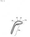
- Fig. 9 there is shown a front view (a plan view) of the armrest covers 43 and 43; in Fig. 10, there is shown a front view (a plan view) thereof as viewed from the rear side; and in Fig. 11, there is shown a schematic sectional view taken along line B-B of Fig. 10.
- the armrest covers 43 and 43 are constituted of cushions 44 and 44 formed with urethane foam or the like; and skin portions 43b and 43b each enveloping a corresponding cushion, and the top ends and front ends thereof are each formed in the shape of being curved outwardly.
- the armrest covers 43 and 43 with the inner side housings 41 and 41 are in conformity with the surfaces of the inner side housings 41 and 41, and the armrest covers 43 and 43 can be attached to the armrest bases 40 and 40 in close contact therewith and there arises no chance for the surfaces of the inner side housings 41 and 41 to be seen through a clearance. Therefore, the inner side housings 41 and 41 of the armrest bases 40 and 40 can be used commonly for massaging machines 1 of different kinds in a design including a color and a shape in appearance, which facilitates a design.
Landscapes
- Health & Medical Sciences (AREA)
- Animal Behavior & Ethology (AREA)
- Pain & Pain Management (AREA)
- Physical Education & Sports Medicine (AREA)
- Rehabilitation Therapy (AREA)
- Life Sciences & Earth Sciences (AREA)
- Epidemiology (AREA)
- General Health & Medical Sciences (AREA)
- Public Health (AREA)
- Veterinary Medicine (AREA)
- Dermatology (AREA)
- Massaging Devices (AREA)
- Chair Legs, Seat Parts, And Backrests (AREA)
Abstract
Provided is a massaging machine (1) with a cover
construction improved on design and maintenance with a suppressed
cost. Amassagingmachine (1) is provided with a back rest portion
(2) and a seat portion (3). The backrest portion (2) includes:
a backrest base (20) having an opening (22) for bringing a
massaging tool (11) of the massaging section (10) into contact
with a user therethrough; an opening cover (23) provided on the
front face of the backrest base (20) so as to cover the opening
(22) thereof and freely detachably attached to the peripheral
edge of the opening (22); and a backrest cover (26) freely
detachably attached to the front face of the backrest base (20)
so as to cover the front face thereof. The seat portion (3)
includes: a seat base (30); a pair of armrest bases (40) provided
at both sides, left and right, of the seat base (30); a seat
cover (31) freely detachably attached on the top face of the
seat base (30) so as to cover the top face; and armrest covers
(43) freely detachably attached on both inner side faces of the
armrest bases (40) so as to cover both inner side faces.
Description
The invention relates to a massaging machine, and in
particular, to a cover construction of a chair-type massaging
machine.
A proposal has been presented on a cover structure of a
backrest portion in a chair-type massaging machine provided with
the backrest portion and a seat portion and having a massaging
section applying massage to a user installed in at least one
of the backrest portion and the seat portion (see, for example,
JP-A No. 2001-276158).
The invention described in the patent literature is to
realize changing a cover without exposing a massaging mechanism
in appearance with a characteristic construction that an inner
cover covering so as to envelop all of a backrest portion base
together with the massaging section is fixedly attached to the
backrest portion base, while an outer cover covering so that
the inner cover is not exposed in appearance is freely detachably
attached to the inner cover. A back pad is provided on a surface
of the backrest portion in contact with a user and the back pad
covers the inner cover without providing the outer cover in an
area covered by the back pad. Another construction has been
disclosed that a cover composite constituted of the inner cover
and the outer cover is used on not only the backrest portion
but also a seat portion and a leg portion of a chair- type massaging
machine. According to the invention of the patent literature,
by applying a variety of designs on an outer cover freely
attachable or detachable, the outer cover can be replaced with
one desired by a consumer without exposing the massaging section
in appearance.
In a massaging machine with a cover structure as described
above, however, since an inner cover covers all of a backrest
portion base, a useless fabric is necessary even in parts covered
by an outer cover and a back pad.
Moreover, in a case where colors of an outer cover and
a back pad are greatly different from one of an inner cover,
exposure of the inner cover through clearances of the peripheral
edges of the outer cover and the back pad in appearance is
unpreferable in terms of design. Still in addition, if a part
of the inner cover preventing a massaging section from being
exposed in appearance is broken or worn out, it requires replacing
the inner cover covering all of the backrest base with a new
one.
In such a way, the construction disclosed in the patent
literature has had a problem associated with cost, design and
maintenance.
The invention has been made in light of the problem and
it is an object of the invention to provide a massaging machine
with a cover construction improved on design and maintenance
with a suppressed cost.
A massaging machine of the invention is, in order to achieve
the object, directed to a chair-type massaging machine equipped
with a backrest portion having a massaging section applying
massage to a user installed therein and a seat portion, wherein
the backrest portion includes: a backrest base having an opening
for bringing a massaging tool of the massaging section into
contact with the user therethrough; an opening cover provided
on the front face of the backrest base so as to cover the opening
thereof and freely detachably attached to the peripheral edge
of the opening; and a backrest cover freely detachably attached
to the front face of the backrest base so as to cover the front
face thereof, while the seat portion includes: a seat base; a
pair of armrest bases provided at both sides, left and right,
of the seat base; a seat cover freely detachably attached on
the top face of the seat base so as to cover the top face; and
armrest covers freely detachably attached on both inner side
faces of the armrest bases so as to cover both inner side faces.
In the construction, the backrest base is preferably
constituted of: a front face housing covered by the attached
backrest cover so as not to be exposed in appearance; and a back
face housing.
It is preferable that the backrest base is equipped with
a detection section detecting an attached/detached state of the
backrest cover and the massaging section installed in the
backrest base is driven only when attachment of the backrest
cover is detected by the detection section.
It is preferable that the armrest bases are each
constituted of: an inner side housing covered by an attached
armrest cover so as not to be exposed in appearance and an outer
side housing.
It is preferable that the top face of the seat base and
both inner side faces of the armrest bases are integrally formed
in a single piece.
It is preferable that the backrest cover, the seat cover
and the armrest covers include : respective cushionmembers, which
are formed so as to hold shapes in conformity with the contact
faces thereof with the backrest base, the seat base and the armrest
bases.
It is preferable that the covers and the corresponding
bases are equipped with attaching/detaching means through
engagement.
According to the invention as defined in claim 1, by
replacing the backrest cover, the seat cover and the armrest
covers with different ones, not only can designs of a massaging
machine be made in various ways, but no unnecessary fabric is
either required to be provided to parts covered by respective
covers; and replacement of an opening cover preventing the
massaging section from being exposed in appearance can be
performed only by detaching the opening cover at the peripheral
edge of the opening of the backrest base.
According to the invention as defined in claim 2, not only
can, by detaching only the back housing, maintenance of the
massaging section be performed, but, by substituting with a back
face housing matching with the backrest cover in color, a design
is also improved more.
According to the invention as defined in claim 3, it can
be prevented to apply a therapeutic power more than necessary
to a user by driving the massaging section in a state where the
backrest cover is not attached and a massaging tool of the
massaging section protrudes outward more than necessary.
According to the invention as defined in claim 4, by
replacing the outer side housing with one matching with the
armrest covers in color, a design is improved more.
According to the invention as defined in claim 5, no
clearance occurs between the seat base and each of the armrest
bases when the seat cover and the armrest covers are removed,
thereby improving safety in cover replacement.
According to the invention as defined in claim 6, since
the covers can be attached to the respective bases in close contact
therewith, which prevents the bases from being seen through the
corresponding clearances, design is improved more.
According to the invention as defined in claim 7, since
can attachment of the covers to the corresponding bases be
performed with ease, but attachment positions are also determined,
efficiency in cover replacement operation and design are improved
more.
More detailed description will be given of the invention
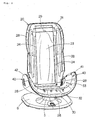
showing an embodiment below. In Fig. 1, there is shown a
perspective view of a massaging machine 1 related to the
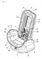
embodiment below; in Fig. 2, there is shown a perspective view
of an appearance of a state where the covers other than an opening
cover (a backrest cover, a seat cover and armrest covers) of
the massaging machine are removed; and in Fig. 3, there is shown
a perspective view of an appearance of a state where all the
covers (an opening cover, a backrest cover, a seat cover and
armrest covers) of the massaging machine are removed.
The massaging machine 1 includes: a backrest portion 2;
a seat portion 3; a pair of armrest portions, left and right,
4 and 4; a leg portion 5; and a base 6. The backrest portion
2 is assembled so as to be able to be reclined rearward and folded
forward around the rear end of the seat portion 3, while the
pair of armrest portions, left and right, 4 and 4, are provided
at both ends, left and right, of the seat portion 3. The top
end of the leg portion 5 is fixed to the bottom face of the seat
portion 3, while the bottom end thereof is freely rotatably
attached to the top face of the base 6.
The backrest portion 2 includes: a backrest base 20
constituted of: a front face housing 21 and a back face housing
25; and a backrest cover 26 (Fig. 4) freely detachably attached
to the front face housing 21 of the backrest base 20 so as to
cover the front face housing 21. A massaging section 10 for
driving a massaging tool 11 applying massage to a user is installed
in the backrest base 20, and the massaging tool 11 is protruded
outward through the opening 22 formed in the front face housing
21 of backrest base 20 and brought into contact with the user.
The massaging section 10 is freely vertically installed
in the backrest base 20 and equipped with a mechanism driving
the massaging tool 11 in a predetermined locus. Averticalmotion
of the massaging section 10 and the mechanism for driving the
massaging tool 11 have only to be operated by known techniques,
wherein, while detailed description thereof is omitted, the
massaging tool 11 is driven from the shoulder of the user to
the waist thereof, forward and rearward, or leftward and
rightward to thereby apply a rubbing massage, tapping massage,
finger pressure massage and back muscle stretching massage to
the user.
As understood from Figs. 2 and 3, when the backrest cover
26 is detached, the front housing 21 of the backrest base 20
is exposed in appearance. The front housing 21 is formed with
a hard synthetic resin or the like, and the opening 22 for bringing
the massaging tool 11 of the massaging section, as described
above, into contact with the user is formed in the middle thereof
in a lateral direction. The opening cover 23 is freely detachably
attached to and along the peripheral edge of the opening 22 so
as to cover it on the front face thereof with attaching means
24 such as screws to thereby prevent the massaging section 10
and the massaging tool 11 from being exposed in appearance.
The opening cover 23 is formed with a synthetic fabric
such as Nylon or polyester with which the massaging tool 11
operates smoothly and which is not worn out in friction on the
massaging tool 11, and since part of a synthetic fabric covering
the opening 22 is loosely spread, wherein the fabric is actually
broader than necessary for covering the opening 22, the massaging
tool 11 protrudes outward from the backrest base 20 and is driven
in the predetermined locus without being hindered in the motion
of the massaging tool 11, thereby difficulty is encountered
breaking the opening cover 23 itself. The opening cover 23 is
formed with a size just attached to the peripheral edge of the
opening 22, in other words, the opening cover 23 does not cover
a surface of the front face housing 21 except for the opening
22 and the peripheral edge thereof.
The front face housing 21 of the backrest base 20 not covered
by the opening cover 23 is not exposed either in appearance during
service by being covered with the backrest cover 26 without a
necessity for providing an unnecessary fabric thereover. In
a case where a necessity occurs for replacement of the opening
cover 23 because of breakage thereof as well, the replacement
with a new one can be done with ease only by cancellation of
fixing the cover at and along the peripheral edge of the opening
22. Since an opening cover 23 is not exposed during operation,
it can be used commonly for massaging machines 1 of different
kinds in a design including a color and a shape in appearance.
Attaching/detaching means 28 is provided at and along the
front face peripheral edge of the front face housing 21 in order
to freely detachably attach the backrest cover 26. The
attaching/detaching means 28 are also attached, as described
later, on a contact face 26a of the backrest cover 26 with the
front face housing (Fig. 5) and attachment of the backrest cover
26 to the front face housing 21 can be easily ensured by engagement
with both attaching/detaching means 28. The
attaching/detaching means 28 to be adopted have only to be known
means such as a Velcro fastener, a fastener or a hook. The
massaging machine 1 in the embodiment adopts both of a Velcro
fastener and a hook; thereby enabling positioning, attachment
and detachment to be realized with ease and certainty.
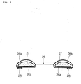
In Fig. 4, there is shown a front view (a plan view) of
the backrest cover 26; in Fig. 5, there is shown a perspective
view of an appearance of the backrest cover 26 as viewed from
the rear side thereof; and in Fig. 6, there is shown a schematic
sectional view along line A-A of Fig. 5. As shown in Figs. 4
to 6, the backrest cover 26 is formed in the shape in which the
top end is bent toward the rear part. The contact face 26a of
the backrest cover 26 with the front face housing 21 is in the
shape in conformity with the front face housing 21 and the backrest
cover 26 can be attached to the backrest base 20 in close contact
therewith without any chance for the front face housing 21 of
the backrest base 20 to be seen through a clearance. Hence,
the front face housing 21 can be used commonly for massaging
machines 1 of different kinds in a design including a color and
a shape in appearance, which facilitates a design.
The backrest cover 26 is of a construction that as shown
in Fig. 6, a part in contact with the opening 22 of the front
face housing 21 is made only of the skin portion 26b and the
other parts are made so that a cushion 27 formed with urethane
foam or the like is enveloped by the skin portion 26b. A shape
of the backrest cover 26 is formed so as to hold a shape of a
cushion 27 included in the skin portion 26b of the backrest cover
26 in conformity with the front face housing 21 constituting
a contact face.
The back face of the backrest cover 26 has the
attaching/detaching means 28 provided at sites slightly inward
from the peripheral edge thereof. The attaching/detaching means
28 are engaged with the attaching/detaching means 28 provided
on the front face housing 21 of the backrest base 20 to thereby
attach the backrest cover 26 to the backrest base 20 in close
contact therewith. Since the attaching/detaching means 28 of
the backrest cover 26 are disposed slightly inward from the
peripheral edge thereof, the front face housing 21 is not exposed
in appearance in a state where the backrest cover 26 is attached
to the backrest base 20; therefore, only the back face housing
25 is repl aced wi th a different one so as to match with the backrest
cover 26 in appearance, shape and color, thereby enabling a
variety of designs in appearance of a massaging machine 1 to
be realized with ease.
A detection section 29 detecting an attachment state of
the backrest cover 26 is, as shown in Figs. 2 and 3, provided
at the top edge of the opening 22 of the backrest base 20. The
detection section 29 is constituted of a known switch or the
like and a detection result is inputted, for example, to a control
circuit of the massaging section 10 described later, thereby
enabling the massaging section 10 installed in the backrest base
20 to be driven only when it is detected that the backrest cover
26 is attached by the detection section 29. In such a way, it
can be prevented that the massaging section 10 applies a
therapeutic power to a user more than necessary by driving the
massaging section 10 in a state where the massaging tool 11 of
the massaging section 10 protruding outward more than necessary.
The seat portion 3, as shown in Figs. 2 and 3, includes:
a seat base 30; and a seat cover 31 (Fig. 7) freely detachably
attached to the top face of the seat base so as to cover it.
The seat base 30 is formed with a hard synthetic resin or the
like, a control circuit for driving and controlling the massaging
section 10 is installed inside the seat base 30 and a lid 32
closing a space accommodating the control circuit is provided
on the top face of the seat base 30. The seat base 30 is formed
so that the top face is curved upwardly at both sides, left and
right, thereof and the curved parts constitute inner side
housings 41 and 41 serving as the both inner side faces of the
armrest bases 40 and 40 of the armrest portions 4 and 4. That
is, the massaging machine 1 of the embodiment of the invention
has the top face of the seat base 30 and both inner side faces
of the armrest bases 40 and 40 integrally formed in a single
piece. With such a construction, when the seat cover 31 and
the armrest covers 43 and 43 (Fig. 9) are removed, no clearance
occurs between the seat base 30 and each of the armrest bases
40 and 40, thereby improving safety in replacement of a cover.
Cushioning members 33 and 33 are attached in the
neighborhoods of both ends, left and right, of the seat base
30. The cushioning members 33 and 33 prevent breakage or the
like from occurring by direct contact between the backrest base
20 and the seat base 30 when the backrest portion 2 is folded
forward in a state where the backrest cover 26 and the seat cover
31 are detached.
Attaching/detaching means 28 are provided on the front
face and the rear end of the top face of the seat base 30 in
order to freely detachably attach the seat cover 31. The
attaching/detaching means 28 are, as described later, also
provided at both ends, forward and rearward, of a contact face
31a of the seat cover 31 with the seat base 30 and attachment
of the seat cover 31 to the seat base 30 can be easily performed
in a similar way to that of the backrest portion 2 by
attaching/detaching means 28 at the both sides. The
attaching/detaching means 28 that are used have only to be known
means such as a Velcro fastener, a fastener and a hook.
In Fig. 7, there is shown a front view (a plan view) of
the seat cover 31; and in Fig. 8, there is shown a perspective
view of an appearance thereof as viewed from the rear side. The
seat cover 31 includes: a cushion (not shown) formed with urethane
foam or the like and a skin portion (attached with no mark)
enveloping it and the front end is formed in the shape of being
curved downward. A contact face 31a with the seat base 30 of
the seat cover 31 is conformity with the top face of the seat
base 30 in shape, the seat cover 31 can be attached to the seat
base 30 in close contact therewith and there is no chance for
the top face of the seat base 30 to be seen through a clearance.
Therefore, the seat base 30 can be used commonly for massaging
machines 1 of different kinds in a design including a color and
a shape in appearance, which facilitates a design.
Attaching/detaching means 28 described above are provided
on the bottom face of the seat cover 31 slightly inward from
the front and rear ends. The attaching/detaching means 28 are
engaged with the attaching/detaching means 28 provided on the
front face of the seat base 30 and at the rear end of the top
face thereof to thereby attach the seat cover 31 to the seat
base 30 in close contact therewith. Since the
attaching/detaching means 28 of the seat cover 31 are provided
slightly inward from the front and rear ends, the seat cover
31 covers the top surface of the seat base 30 with certainty.
The armrest portions 4 and 4 in Figs. 2 and 3 includes:
armrest bases 40 and 40; and armrest covers 43 and 43 (Fig. 9).
The armrest bases 40 and 40 includes: the inner side housings
41 and 41; and the outer side housings 42 and 42 attached to
the inner side housings 41 and 41 on the outer sides thereof.
The armrest covers 43 and 43 are attached to the inner side housings
41 and 41 of the armrest bases 40 and 40 so as to cover them.
The attaching/detaching means 28 are provided on the top
ends of the inner side housings 41 and 41 of the armrest bases
40 and 40 and the front end peripheral edges thereof so as to
freely detachably attach the armrest covers 43 and 43 to the
inner side housings 41 and 41. The attaching/detaching means
28 are, as described later, also provided on a contact face 43a
of the armrest covers 43 and 43 with the inner side housings
41 and 41, attachment of the armrest covers 43 and 43 to the
armrest bases 40 and 40 can be performed with ease in a similar
way to that of the backrest portion 2 and the seat portion 3
by engagement between both sets of the attaching/detaching means
28. The attaching/detaching means 28 that are used have only
to be known means such as a Velcro fastener, a fastener and a
hook.
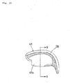
In Fig. 9, there is shown a front view (a plan view) of
the armrest covers 43 and 43; in Fig. 10, there is shown a front
view (a plan view) thereof as viewed from the rear side; and
in Fig. 11, there is shown a schematic sectional view taken along
line B-B of Fig. 10. The armrest covers 43 and 43 are constituted
of cushions 44 and 44 formed with urethane foam or the like;
and skin portions 43b and 43b each enveloping a corresponding
cushion, and the top ends and front ends thereof are each formed
in the shape of being curved outwardly. Contact faces 43a and
43a of the armrest covers 43 and 43 with the inner side housings
41 and 41 are in conformity with the surfaces of the inner side
housings 41 and 41, and the armrest covers 43 and 43 can be attached
to the armrest bases 40 and 40 in close contact therewith and
there arises no chance for the surfaces of the inner side housings
41 and 41 to be seen through a clearance. Therefore, the inner
side housings 41 and 41 of the armrest bases 40 and 40 can be
used commonly for massaging machines 1 of different kinds in
a design including a color and a shape in appearance, which
facilitates a design.
Attaching/detaching means 28 described above are provided
on the contact faces 43a and 43a of the armrest covers 43 and
43 with the inner side housings 41 and 41, respectively, on the
top ends and slightly inwardly from the peripheral edges of the
front end thereof. Engagement occurs between the
attaching/detaching means 28 described just above with the
attaching/detaching means 28 provided on the inner side housings
41 and 41 of the armrest bases 40 and 40 on the top end and at
the peripheral edges of the front end thereof to thereby attach
the armrest covers 43 and 43 to the armrest bases 40 and 40 in
close contact therewith. Since the attaching/detaching means
28 of the armrest covers 43 and 43 are provided slightly inward
from the peripheral edge thereof, the armrest covers 43 and 43
cover the inner side housings 41 and 41 of the armrest bases
40 and 40 with certainty.
In such a way, since the inner side housings 41 and 41
are not exposed in appearance in a state of the armrest covers
43 and 43 being attached to the armrest bases 40 and 40,
respectively, only the outer side housings 42 and 42 are replaced
so as to match with the armrest covers 43 and 43 in appearance,
shape and color without changing the inner side housings 41 and
41, thereby enabling a variety of designs in appearance of a
massaging machine 1 to be easily realized.
Claims (7)
- A massaging machine (1) of a chair-type equipped with a backrest portion (2) having a massaging section (10) applying massage to a user installed therein and a seat portion (3),
wherein said backrest portion (2) includes: a backrest base (20) having an opening (22) for bringing a massaging tool (11) of said massaging section (10) into contact with said user therethrough; an opening cover(23) provided on the front face of said backrest base (20) so as to cover said opening (22) thereof and freely detachably attached to the peripheral edge of said opening (22); and a backrest cover (26) freely detachably attached to said front face of said backrest base (20) so as to cover said front face thereof,
while said seat portion (3) includes: a seat base (30); a pair of armrest bases (40) provided at both sides, left and right, of said seat base (30) ; a seat cover (31) freely detachably attached on the top face of said seat base (30) so as to cover said top face; and armrest covers (43) freely detachably attached on both inner side faces of said armrest bases (40) so as to cover both inner side faces. - The massaging machine (1) according to claim 1, wherein said backrest base (20) is constituted of: a front face housing (21) covered by said attached backrest cover (26) so as not to be exposed in appearance; and a back face housing (25).
- The massaging machine (1) according to claim 1, wherein said backrest base (20) is equipped with a detection section (29) detecting an attached/detached state of said backrest cover (26) and said massaging section (10) installed in said backrest base (20) is driven only when attachment of said backrest cover (26) is detected by said detection section (29).
- The massaging machine (1) according to claim 1, wherein said armrest bases (20) are each constituted of: an inner side housing (41) covered by an attached armrest cover (43) so as not to be exposed in appearance and an outer side housing (42).
- The massaging machine (1) according to claim 1, wherein the top face of said seat base (30) and both inner side faces of said armrest bases (40) are integrally formed in a single piece.
- The massaging machine (1) according to claim 1, wherein said backrest cover (26), said seat cover (31) and said armrest covers (43) include: respectivecushionmembers, which are formed so as to hold shapes in conformity with the contact faces thereof with said backrest base (20), said seat base (30) and said armrest bases (40).
- The massaging machine (1) according to claim 1, wherein said covers and said corresponding bases are equipped with attaching/detaching means through engagement.
Applications Claiming Priority (2)
| Application Number | Priority Date | Filing Date | Title |
|---|---|---|---|
| JP2004158584 | 2004-05-28 | ||
| JP2004158584A JP2005334386A (en) | 2004-05-28 | 2004-05-28 | Massage machine |
Publications (1)
| Publication Number | Publication Date |
|---|---|
| EP1600136A1 true EP1600136A1 (en) | 2005-11-30 |
Family
ID=34936839
Family Applications (1)
| Application Number | Title | Priority Date | Filing Date |
|---|---|---|---|
| EP05011131A Withdrawn EP1600136A1 (en) | 2004-05-28 | 2005-05-23 | Massaging machine |
Country Status (5)
| Country | Link |
|---|---|
| EP (1) | EP1600136A1 (en) |
| JP (1) | JP2005334386A (en) |
| KR (1) | KR20060045900A (en) |
| CN (1) | CN1720889A (en) |
| TW (1) | TW200608957A (en) |
Cited By (1)
| Publication number | Priority date | Publication date | Assignee | Title |
|---|---|---|---|---|
| US7311681B1 (en) | 2006-06-12 | 2007-12-25 | Christalla Vaccarella | Motor vehicle massage seat |
Families Citing this family (14)
| Publication number | Priority date | Publication date | Assignee | Title |
|---|---|---|---|---|
| JP4711909B2 (en) * | 2006-08-11 | 2011-06-29 | 三洋電機株式会社 | Chair type massage machine |
| JP4893571B2 (en) * | 2007-09-28 | 2012-03-07 | パナソニック電工株式会社 | Chair type massage machine |
| WO2009134096A2 (en) | 2008-04-30 | 2009-11-05 | Nam Ki-Won | Control system and method for advertisement exposure |
| JP4840429B2 (en) * | 2008-09-25 | 2011-12-21 | パナソニック電工株式会社 | Massage machine |
| JP5237755B2 (en) * | 2008-10-28 | 2013-07-17 | パナソニック株式会社 | Massage machine |
| JP5081275B2 (en) * | 2010-05-31 | 2012-11-28 | パナソニック株式会社 | Massage machine |
| JP2011250837A (en) * | 2010-05-31 | 2011-12-15 | Panasonic Electric Works Co Ltd | Massage machine |
| KR200472042Y1 (en) * | 2012-10-02 | 2014-04-01 | 매직라이프코리아(주) | Massage chair having detachable side pannel |
| KR101570122B1 (en) | 2013-06-24 | 2015-11-24 | 남기원 | Interactive advertisement display system based on smart-phone |
| JP6739953B2 (en) * | 2016-03-16 | 2020-08-12 | 株式会社フジ医療器 | Backrest of massage machine and massage machine |
| KR20190136204A (en) | 2018-05-30 | 2019-12-10 | 윤지원 | Online advertisement exposure control system and advertisement exposure control method |
| KR102325702B1 (en) * | 2021-04-21 | 2021-11-12 | 주식회사 텐마인즈 | Massage chair that can replace the seat |
| JP2022187432A (en) * | 2021-06-07 | 2022-12-19 | ファミリーイナダ株式会社 | Massage device and maintenance method |
| JP2024008470A (en) * | 2022-07-08 | 2024-01-19 | 株式会社フジ医療器 | Chair massage machine and its ordering system |
Citations (5)
| Publication number | Priority date | Publication date | Assignee | Title |
|---|---|---|---|---|
| JPH03267014A (en) * | 1990-03-16 | 1991-11-27 | Fuji Iryoki:Kk | Covering body for chair |
| JPH10263034A (en) * | 1997-03-26 | 1998-10-06 | T S Tec Kk | Heated cover for massage chair |
| US6056708A (en) * | 1997-04-30 | 2000-05-02 | Matsushita Electric Works, Ltd. | Massaging apparatus having frame with opening and a cover stretched over frame |
| JP2000334016A (en) * | 1999-05-26 | 2000-12-05 | Matsushita Electric Works Ltd | Relax chair |
| JP2001276158A (en) * | 2001-03-15 | 2001-10-09 | Family Kk | Massage machine cover structure |
-
2004
- 2004-05-28 JP JP2004158584A patent/JP2005334386A/en active Pending
-
2005
- 2005-05-04 KR KR1020050037518A patent/KR20060045900A/en not_active Ceased
- 2005-05-23 EP EP05011131A patent/EP1600136A1/en not_active Withdrawn
- 2005-05-24 CN CN200510073779.0A patent/CN1720889A/en active Pending
- 2005-05-25 TW TW094117000A patent/TW200608957A/en unknown
Patent Citations (5)
| Publication number | Priority date | Publication date | Assignee | Title |
|---|---|---|---|---|
| JPH03267014A (en) * | 1990-03-16 | 1991-11-27 | Fuji Iryoki:Kk | Covering body for chair |
| JPH10263034A (en) * | 1997-03-26 | 1998-10-06 | T S Tec Kk | Heated cover for massage chair |
| US6056708A (en) * | 1997-04-30 | 2000-05-02 | Matsushita Electric Works, Ltd. | Massaging apparatus having frame with opening and a cover stretched over frame |
| JP2000334016A (en) * | 1999-05-26 | 2000-12-05 | Matsushita Electric Works Ltd | Relax chair |
| JP2001276158A (en) * | 2001-03-15 | 2001-10-09 | Family Kk | Massage machine cover structure |
Non-Patent Citations (4)
| Title |
|---|
| PATENT ABSTRACTS OF JAPAN vol. 016, no. 076 (C - 0914) 25 February 1992 (1992-02-25) * |
| PATENT ABSTRACTS OF JAPAN vol. 1999, no. 01 29 January 1999 (1999-01-29) * |
| PATENT ABSTRACTS OF JAPAN vol. 2000, no. 15 6 April 2001 (2001-04-06) * |
| PATENT ABSTRACTS OF JAPAN vol. 2002, no. 02 2 April 2002 (2002-04-02) * |
Cited By (1)
| Publication number | Priority date | Publication date | Assignee | Title |
|---|---|---|---|---|
| US7311681B1 (en) | 2006-06-12 | 2007-12-25 | Christalla Vaccarella | Motor vehicle massage seat |
Also Published As
| Publication number | Publication date |
|---|---|
| JP2005334386A (en) | 2005-12-08 |
| TW200608957A (en) | 2006-03-16 |
| CN1720889A (en) | 2006-01-18 |
| KR20060045900A (en) | 2006-05-17 |
Similar Documents
| Publication | Publication Date | Title |
|---|---|---|
| US6421841B2 (en) | Inside pad for helmet and helmet using this inside pad | |
| US5836645A (en) | Lounger-type massage machine | |
| KR100323185B1 (en) | Helmet pads for internal organs and internal organs | |
| JP2005334386A (en) | Massage machine | |
| TWI421068B (en) | Head massage apparatus | |
| KR101767390B1 (en) | Multi Massage Device | |
| JP2008049081A (en) | Backrest and chair | |
| JPH10195707A (en) | Helmet removable interior structure | |
| KR20000016762A (en) | Massaging apparatus | |
| JP3128833U (en) | Headrest cover with necklace | |
| JP7461049B2 (en) | mask | |
| KR200324066Y1 (en) | a seat cover with electromotive massage function | |
| KR20200137490A (en) | Neck skin beauty device and neck skin beauty device set having the same | |
| JP2006325645A (en) | Massage machine | |
| KR101704752B1 (en) | Cushion detachable massage sofa | |
| KR200398278Y1 (en) | Chair | |
| JP3027123B2 (en) | Diving face mask | |
| JP7621219B2 (en) | Massage equipment | |
| KR20010110279A (en) | vehicle seat-cover with vibration motor | |
| JPH0444590Y2 (en) | ||
| CN121287474A (en) | massager | |
| JP2007117600A (en) | Chair | |
| JPH0519296Y2 (en) | ||
| CN210783667U (en) | Soft cushion for wheelchair | |
| CN121287475A (en) | massager |
Legal Events
| Date | Code | Title | Description |
|---|---|---|---|
| PUAI | Public reference made under article 153(3) epc to a published international application that has entered the european phase |
Free format text: ORIGINAL CODE: 0009012 |
|
| AK | Designated contracting states |
Kind code of ref document: A1 Designated state(s): AT BE BG CH CY CZ DE DK EE ES FI FR GB GR HU IE IS IT LI LT LU MC NL PL PT RO SE SI SK TR |
|
| AX | Request for extension of the european patent |
Extension state: AL BA HR LV MK YU |
|
| AKX | Designation fees paid | ||
| STAA | Information on the status of an ep patent application or granted ep patent |
Free format text: STATUS: THE APPLICATION IS DEEMED TO BE WITHDRAWN |
|
| 18D | Application deemed to be withdrawn |
Effective date: 20060531 |
|
| REG | Reference to a national code |
Ref country code: DE Ref legal event code: 8566 |