EP1600103A1 - Device for measuring ealstic characteristics of organism tissue - Google Patents
Device for measuring ealstic characteristics of organism tissue Download PDFInfo
- Publication number
- EP1600103A1 EP1600103A1 EP04709694A EP04709694A EP1600103A1 EP 1600103 A1 EP1600103 A1 EP 1600103A1 EP 04709694 A EP04709694 A EP 04709694A EP 04709694 A EP04709694 A EP 04709694A EP 1600103 A1 EP1600103 A1 EP 1600103A1
- Authority
- EP
- European Patent Office
- Prior art keywords
- displacement
- tissue
- stress
- canal
- profile
- Prior art date
- Legal status (The legal status is an assumption and is not a legal conclusion. Google has not performed a legal analysis and makes no representation as to the accuracy of the status listed.)
- Withdrawn
Links
- NHIDGVQVYHCGEK-UHFFFAOYSA-N C=CCC1CCCC1 Chemical compound C=CCC1CCCC1 NHIDGVQVYHCGEK-UHFFFAOYSA-N 0.000 description 2
Images





Classifications
-
- A—HUMAN NECESSITIES
- A61—MEDICAL OR VETERINARY SCIENCE; HYGIENE
- A61B—DIAGNOSIS; SURGERY; IDENTIFICATION
- A61B5/00—Measuring for diagnostic purposes; Identification of persons
- A61B5/22—Ergometry; Measuring muscular strength or the force of a muscular blow
- A61B5/224—Measuring muscular strength
- A61B5/227—Measuring muscular strength of constricting muscles, i.e. sphincters
-
- A—HUMAN NECESSITIES
- A61—MEDICAL OR VETERINARY SCIENCE; HYGIENE
- A61B—DIAGNOSIS; SURGERY; IDENTIFICATION
- A61B5/00—Measuring for diagnostic purposes; Identification of persons
- A61B5/103—Measuring devices for testing the shape, pattern, colour, size or movement of the body or parts thereof, for diagnostic purposes
-
- A—HUMAN NECESSITIES
- A61—MEDICAL OR VETERINARY SCIENCE; HYGIENE
- A61B—DIAGNOSIS; SURGERY; IDENTIFICATION
- A61B5/00—Measuring for diagnostic purposes; Identification of persons
- A61B5/103—Measuring devices for testing the shape, pattern, colour, size or movement of the body or parts thereof, for diagnostic purposes
- A61B5/107—Measuring physical dimensions, e.g. size of the entire body or parts thereof
- A61B5/1076—Measuring physical dimensions, e.g. size of the entire body or parts thereof for measuring dimensions inside body cavities, e.g. using catheters
-
- A—HUMAN NECESSITIES
- A61—MEDICAL OR VETERINARY SCIENCE; HYGIENE
- A61B—DIAGNOSIS; SURGERY; IDENTIFICATION
- A61B5/00—Measuring for diagnostic purposes; Identification of persons
- A61B5/43—Detecting, measuring or recording for evaluating the reproductive systems
- A61B5/4306—Detecting, measuring or recording for evaluating the reproductive systems for evaluating the female reproductive systems, e.g. gynaecological evaluations
- A61B5/4318—Evaluation of the lower reproductive system
- A61B5/4337—Evaluation of the lower reproductive system of the vagina
-
- A—HUMAN NECESSITIES
- A61—MEDICAL OR VETERINARY SCIENCE; HYGIENE
- A61B—DIAGNOSIS; SURGERY; IDENTIFICATION
- A61B5/00—Measuring for diagnostic purposes; Identification of persons
- A61B5/68—Arrangements of detecting, measuring or recording means, e.g. sensors, in relation to patient
- A61B5/6846—Arrangements of detecting, measuring or recording means, e.g. sensors, in relation to patient specially adapted to be brought in contact with an internal body part, i.e. invasive
- A61B5/6885—Monitoring or controlling sensor contact pressure
-
- A—HUMAN NECESSITIES
- A61—MEDICAL OR VETERINARY SCIENCE; HYGIENE
- A61B—DIAGNOSIS; SURGERY; IDENTIFICATION
- A61B2562/00—Details of sensors; Constructional details of sensor housings or probes; Accessories for sensors
- A61B2562/04—Arrangements of multiple sensors of the same type
- A61B2562/046—Arrangements of multiple sensors of the same type in a matrix array
-
- A—HUMAN NECESSITIES
- A61—MEDICAL OR VETERINARY SCIENCE; HYGIENE
- A61B—DIAGNOSIS; SURGERY; IDENTIFICATION
- A61B5/00—Measuring for diagnostic purposes; Identification of persons
- A61B5/45—For evaluating or diagnosing the musculoskeletal system or teeth
- A61B5/4519—Muscles
Definitions
- the present invention relates to a device for measuring elastic properties of a living tissue.
- an operation is performed to recover the elasticity of the muscle supporting the urethra by, for example, providing a support hole on a pelvis through which the muscle surrounding the urethra are lifted up.
- training for recovering the elasticity of the muscle surrounding the urethra can be provided.
- the extent of reduction in the muscle elasticity which causes urinary incontinence cannot sufficiently be evaluated by a topical measurement such as measurement at one point inside the vaginal canal. The same is true for an evaluation of elasticity recovery after operation or during training. That is, it is impossible to evaluate which part of muscle has been recovered and which part of muscle has not been recovered.
- the present invention advantageously provides a device for measuring elastic properties of living tissue which allows for real-time measurement of dilatation and contraction properties of the living tissue, and solves the problems noted above.
- the present invention further advantageously provides a device for measuring elastic properties of a living tissue by which dilatation and contraction properties of the living tissue can easily be understood.
- a device for measuring elastic properties of living tissue is a device for measuring elastic properties of a living tissue by which elastic properties of a tissue surrounding a canal of a living body is measured by inserting the device through the canal, characterized by comprising a probe base to be inserted through the canal; a plurality of probes provided around an insertion axis of the probe base and at the same insertion depth in a direction of the insertion axis the probes being placed in close vicinity to the tissue inside the canal so as to be driven in a manner being pressed against and withdrawn from a plurality of measurement positions on the tissue; a plurality of stress detection sensors provided on the respective probes, each of which detects a stress applied to the tissue at each measurement position on the basis of a reaction force from the tissue when the probe is driven so as to be pressed and withdrawn; a plurality of displacement detection sensors provided corresponding to respective stress detection sensors, each of which detects a displacement of the tissue at each measurement position on the basis of a displacement
- a plurality of probes inserted through the canal are provided around the insertion axis at the same insertion depth in a direction of the insertion axis.
- the plurality of probes are driven so as to be pressed against and withdrawn from the plurality of measurement positions on the tissue inside the canal, and then a stress and a displacement at each measurement position are detected.
- a displacement profile produced by the pressing and withdrawing motion is calculated from a standard profile of the canal and from the displacement at each measurement position, and then displayed together with a change of stress. Therefore, it is possible to measure the dilatation and contraction properties inside the canal such as a vagina in real time.
- visually displaying a change of the displacement profile allows a patient to easily understand the dilatation and contraction properties of the living tissue, for example.
- the standard profile is preferably a tomogram at the above described insertion depth into the canal.
- the display means preferably displays a displacement profile and further displays graphics of a size corresponding to each value of the stress at the each measurement positions so as to be superimposed on positions corresponding to measurement position on the displacement profile.
- the change of stress can be measured in real time in association with the change of displacement profile, and can be observed visually.
- the displacement profile calculation part preferably calculates a displacement profile by interpolation between adjacent measurement positions, based on the each displacements at the each measurement position. According to the above described configuration, it is possible to measure in real time and observe visually not only a change in displacement at each of discrete measurement positions but also a change of an overall cross sectional view of the tissue.
- each plurality of probes is further preferably provided at a plurality of insertion depths, respectively. According to the above described configuration, it is possible not only to perform measurement around an inner periphery of the canal but also to perform measurement in a depth direction of the canal.
- the device for measuring elastic properties of a living tissue is characterized by further comprising storage means for storing displacement profiles and stress values corresponding to the profiles at respective measurement times, wherein the display means read the displacement profiles at the respective measurement times and the corresponding respective stress values from the storage means to display thereof, respectively.
- the present invention it is possible to display on the same screen a situation in which the displacement profile is changing every moment. In addition, it is also possible to display on the same screen a situation in which the stress is changing every moment. Further, it is possible to display on the same screen a situation in which the displacement profile and the stress change from moment to moment.
- the device for measuring elastic properties of a living tissue preferably comprises transmission means for transmitting the displacement profiles at the respective measurement times and the respective stress values corresponding to the profiles to the outside.
- transmission means for transmitting the displacement profiles at the respective measurement times and the respective stress values corresponding to the profiles to the outside.
- the same data can be measured and observed at a plurality of locations. For example, a patient can observe the elastic properties of the living tissue at home while transmitting the date to a doctor or the like, and then can receive appropriate instructions.
- a device for measuring elastic properties of living tissue is a device for measuring elastic properties of a living tissue by which elastic properties of a tissue surrounding a canal of a living body is measured by inserting the device through the canal, characterized by comprising a probe base to be inserted through the canal; a plurality of probes provided around an insertion axis of the probe base and at the same insertion depths in a direction of the insertion axis, the probes being placed in close vicinity to the tissue inside the canal so as to be driven in a manner being pressed against and withdrawn from a plurality of measurement positions on the tissue; a plurality of hardness sensor parts provided on respective probes; hardness detection means for detecting a hardness of the tissue at each measurement position, based on a signal from the hardness sensor part; a plurality of displacement detection sensors provided corresponding to the respective hardness sensor parts, each of which detects a displacement of the tissue at each measurement position on the basis of a displacement of each hardness sensor part with respect to the
- hardness and displacement of the tissue can be evaluated. Because the hardness is closely related to an elastic coefficient which is a ratio of a stress to a strain, it is possible to measure and observe in real time a change associated with an elastic coefficient of the tissue from a change of hardness.
- a device for measuring elastic properties of a living tissue is characterized in that the above described hardness sensor part comprises a vibrator, a vibration detection sensor, an input terminal connected to the vibrator, and an output terminal connected to the vibration detection sensor; and the above described hardness detection means comprises an amplifier whose input terminal is connected to the output terminal of the hardness sensor part, and a phase shift circuit provided between the output terminal of the amplifier and the input terminal of the hardness sensor part so as to shift a phase difference to zero by modulating a frequency when the phase difference is produced between an input waveform to the vibrator and an output waveform from the vibration detection sensor, wherein the hardness of the tissue is detected from a change of frequency which is caused by a change in hardness of the tissue while keeping a resonant condition of a closed loop which comprises the hardness sensor part and the tissue.
- the above described hardness detection means comprises an amplifier whose input terminal is connected to the output terminal of the hardness sensor part, and a phase shift circuit provided between the output terminal of the amplifier and the input terminal of the hard
- the present invention makes it possible to measure the dilatation and contraction properties of living tissue in real time.
- the device for measuring elastic properties of living tissue of to the present invention dilatation and contraction properties of the living tissue can easily be understood.
- vagina is used as an example of a living body canal in the following description
- the invention is obviously applicable to body canals other than the vagina such as, for example, the pharynx, the anal canal, the colon, or an auditory tube.
- body canals other than the vagina such as, for example, the pharynx, the anal canal, the colon, or an auditory tube.
- shape, size, or structure of a tip portion of a probe part may be easily modified for applications involving living body cavities, such as the heart or stomach.
- Figure 1 is a drawing showing a configuration of a device for measuring elastic properties 10.
- the device for measuring elastic properties 10 is inserted into a vagina 22 of a living body (a patient) 20, and is also configured by comprising a probe part 40 for detecting a signal with respect to elastic properties of a living tissue of an inner wall 24 of the vagina 22, a signal cable 90, and a main part 100 of the device for processing and displaying the signal detected by the probe 40.
- the probe 40 comprises a probe base 42, four probes 50 attached towards the tip end of the probe base 42, a sleeve 44 slidably fitted into an outer periphery of the probe base 42, and a flange plate 46 which is for guiding an outer periphery of the sleeve 44 and is to be applied to a vaginal introitus.
- the probe base 42 is a rod-like member measuring several millimeters per side or in diameter. Signal lines from respective four probes 50 are housed within the probe base 42, and the signal lines extend out of a rear end portion of the probe base 42 toward the outside so as to be connected to the signal cable 90. An outer periphery of a rear end side of the probe base 42 is divided by scale marks 48 which represent the insertion depth of the probe base into the vagina 22 with respect to the flange plate 46.
- Each of the respective probes 50 comprises a leaf spring 52, one end of which is attached to the probe base 42, and a sensor part 54 provided on a free end of the leaf spring 52.
- One end of each of the respective leaf springs 52 is provided at the same insertion depth in a direction of an axis of the probe base 42 such that these springs are symmetrically placed at intervals of 90° around the outer periphery of the probe base 42.
- Figure 2 is a drawing of the tip of the probe part as viewed from a deep portion of the vagina.
- Figure 3 is a drawing illustrating a relationship among the probe base 42, the sleeve 44, and the probe 50.
- the pipe-like inside of the sleeve 44 comes into contact with the leaf spring 52 of the probe 50, and when the sleeve 44 further moves toward the left side, the sleeve 44 acts so as to press the leaf spring 52 toward the probe base 42. Therefore, the sensor part 54 provided at the free end of the leaf spring 52 moves in a downward direction as the sleeve 44 moves toward the left side, and moves in an upward direction as the sleeve 44 moves toward the right side.
- the relative movement between the sleeve 44 and the probe part 42 allows the sensor part 54 provided at the free end of the leaf spring 52 to be driven in a manner of being pressed against and withdrawn from the tissue inside the vagina.
- the relative movement between the sleeve 44 and the probe base 42 can be achieved by a small-sized motor (not shown). Further, in simple measurement, the relative movement between the sleeve 44 and the probe base 42 can also be achieved by manual operation of an operator.
- the whole of the probe 50 including the sensor part 54 can also be housed within the sleeve 44.
- the tip of the probe part 40 can be inserted to a predetermined depth in the vagina while the probe 50 having a complicated mechanism is housed within the sleeve 44, so that the insertion can be smoothly performed.
- Control of the insertion depth can be achieved by using the flange plate 46 and the scale marks ticked on the probe base 42. Then, by moving the sleeve 44 at the predetermined insertion depth, the four probes 50 can be opened and shut like an umbrella within the vagina.
- the number of probes is not limited to four, and two, three, or five or more probes may be used.
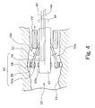
- Figure 4 is a detail view around the probe 50 including the sensor part 54.
- the probe 50 is so formed that a generally semi-spherical plastic contact ball 58 having a stress detection base 56 is fitted to a free end of the leaf spring 52 attached to an outer periphery of the probe base 42, and a stress detection sensor 60 is adhered on the stress detection bases 56.
- a displacement detection sensor 62a is placed on one side of the leaf spring 52 opposite the side to which the stress detection base 56 is attached, and a displacement detection sensor 62b is placed on a surface of the probe base 42 facing to the displacement detection sensor 62a, such that these two sensors 62a and 62b are paired with each other.
- Signal lines 92 and 94 are connected to the stress detection sensor 60 and the displacement detection sensors 62a, 62b respectively, and introduced into a signal cable 90 passing through the probe base 42 as described above.
- a strain gauge may be used as the stress detection sensor 60.
- a light-receiving element paired with a light-emitting element may be used as the displacement detection sensors 62a, 62b.
- other small-sized proximity sensors such as a magnet paired with a magnetometric sensor, may also be used as the displacement detection sensor.
- the stress detection bases 56 and the contact ball 58 may be made from the same material or may be made from different materials in a laminated structure.
- FIG 5 is a segmentary view of the probe 50 provided with a hardness sensor part 55. Elements corresponding to those of the example of Figure 4 are given the same reference numerals, and their detailed descriptions will not be repeated.
- the hardness sensor part 55 is so formed that a vibrator 64 and a vibration detection sensor 66 are laminated on a free end of the leaf spring 52 by using an adhesive or the like and a generally semi-spherical plastic contact ball 58 is adhesively attached to the laminate.
- a displacement detection sensor 62a and a displacement detection sensor 62b paired therewith are respectively placed on an opposite side of the leaf spring 52 and on a surface of the probe base 42 facing thereto, as illustrated in Figure 4.
- Signal lines 96a and 96b are respectively connected to the vibrator 64 and the vibration detection sensor 66, and these signal lines 96a and 96b are introduced into a hardness detection part described below passing through the probe base 42 and via a signal cable 90 as described above.
- the probe part 40 of the above described configuration will now be described.
- the probe part 42 and the sleeve 44 are inserted from an opening of the flange plate 46 to a certain insertion depth at which the elastic properties of the canal such as a vagina 22 of a patient are to be measured.
- the sleeve 44 is gradually moved toward a proximal end (indicated by an arrow in Figure 1) with respect to the probe base 42 by manual operation of the operator or by a small-sized motor, in any even such that the probes 50 open like an umbrella.
- the contact ball 58 moves toward the tissue inside the vagina 22, and then the contact ball 58 is pressed so as to dilate an inner wall of the vagina 22. Subsequently, the sleeve 44 is gradually returned toward the left side with respect to the probe base 42, and the probes 50 are gradually shut. At this point, the contact ball 58 moves away from the tissue inside the vagina 22, and then the contact ball 58 is returned in response to contraction of the inner wall of the vagina 22.
- the position of an inner wall (24a, 24b, and 24c) of the vagina 22 will change from an inner wall 24a in an initial condition to an inner wall 24b in a dilatation condition, and to an inner wall 24c in a contraction condition, in response to pressing and releasing (withdrawing) motion of the contact ball 58.
- a reaction force F caused by dilatation and contraction of the inner wall of the vagina 22 is detected by a stress detection sensor 60 provided on a stress detection base 56 to which the contact ball 58 is attached. If the stress detection sensor 60 is a strain gauge, the reaction force becomes a signal representing a change in resistance and is transmitted through the signal line 92 to a main part 100 of the device, where the signal is processed and calculated in terms of a stress.
- a change in distance between the probe base 42 and the contact ball 58 that is, a relative displacement of dilatation and contraction of the inner wall of the vagina 22 caused by the contact ball 58 is detected by the displacement detection sensors 62a, 62b. That is, when a distance between the probe base 42 and the contact ball changes, a distance between the light-emitting element and the light-receiving element also changes. And corresponding to the change in distance, a signal which represents a change in light-receiving amount is generated and transmitted through the signal line 94 to the main part 100 of the device, where the signal is processed and calculated in terms of a displacement, for establishing an association with the previously determined stress.
- Figure 6 shows an example in which the above-described leaf spring structure is replaced with a balloon which can be freely expanded and contracted in response to fluid pressure.
- a balloon 70 is attached to the probe base 42.
- An inner wall of the balloon 70 is provided with a probe 54.
- the balloon 70 is connected to a pump 72, and is driven so as to be pressed against and released from the tissue by adjusting the pressure of the pump 72.
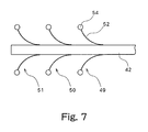
- Figure 7 shows an example in which four probes 49, 50, and 51 are provided at each of three different insertion depths.
- a single sleeve can be used to gradually open the three sets of probes in increasing order of insertion depth and can also be used to gradually shut the probes in decreasing order of insertion depth.
- Three partial sleeves, which are respectively placed between the probe 51 and the probe 50, between the probe 50 and the probe 49, and at a proximal portion of the probe base with respect to the probe 49, may also be used to independently drive the respective probes 49, 50, and 51 to be pressed and released by providing a mechanism for individually and slidably moving these partial sleeves by remote control or the like.
- the insertion depth of the probe is not limited to the above described three levels, but may be set as appropriate depending on convenience in measurement.
- Figure 8 is a block diagram of a main part 100 of the device.
- the main part of the device can be configured by additionally providing a common computer with an interface circuit substrate for stress measurement, an interface circuit substrate for displacement measurement, a hardness detection part circuit substrate for hardness measurement, and the like.
- the hardness detection part circuit substrate may also be configured as an independent device, to which a common computer is connected.
- the main part 100 of the device comprises a CPU 102, an input part 104 such as a keyboard, an output part 106 such as a display, a transmission control part 108 connected via a network or the like to an external diagnostic device, and a storage device 110 in which data and the like calculated or generated by the CPU 102 are stored.
- the main part 100 of the device is also provided with a stress sensor I/F (InterFace) 112, a displacement sensor I/F 114, and a hardness detection part 116, connected to signal lines 92, 94, and 96, respectively.
- Each element of the main parts is connected with internal bus line.
- the stress sensor I/F (InterFace) 112 in the above described example is a circuit which has a function of performing the conversion processing or the like for the purpose of digital signal processing on a change in resistance detected by the stress detection sensor 60.
- the displacement sensor I/F 114 is a circuit which has a function of performing the conversion processing or the like for the purpose of digital signal processing on a change in light-receiving amount detected by displacement detection sensors 62a, 62b.
- FIG. 9 is a block diagram of the hard detection part 116.
- the hard detection part 116 comprises an input terminal 140 connected to the vibrator 64 of the hard sensor part 55 via a signal line 96a and an output terminal 142 connected to the vibration detection sensor 66 via a signal line 96b.
- the hard detection part 116 also comprises an amplifier 144 whose input terminal is connected to the output terminal 142, and a phase shift circuit 146 provided between the output terminal of the amplifier 144 and the input terminal 140 so as to shift a phase difference to zero by modulating a frequency when the phase difference is produced between an input waveform to the vibrator 64 and an output waveform from the vibration detection sensor 66.
- Description of a phase shift circuit having the above described functions can be found in, for example, Japanese Patent Laid-Open Publication No. Hei 9-145691.
- any change in frequency resulting from a change in hardness of the tissue is detected by a frequency deviation detection part 148, and converted to a signal indicating the hardness by a hardness converter 150.
- the converted hardness signal is then converted to a digital signal.
- a conversion table or the like calibrated by a standard substance for example. In this way, a quantitative value for the hardness of the organism can be obtained.
- a stress calculation module 120 has a calculation function such that a digital signal which represents a resistance change being input from the stress I/F 112 is subjected to the operational processing which utilizes a gauge factor of a stress gauge, for example, thereby converting a reaction force exerted on the contact ball at the tip of the probe into a digital value representing the stress on the living body tissue of the inner wall of the vagina.
- a displacement calculation module 122 has a calculation function such that a digital signal which represents the change in the light-receiving amount input from the displacement sensor I/F 114 is subjected to the operational processing which utilizes a relational equation between a distance from a light-emitting element to a light-receiving element and a change in an light-receiving amount, thereby converting a moving amount of the contact ball at a tip of the probe into a digital value representing the displacement of the living body tissue of the inner wall of the vagina.
- a displacement profile calculation module 124 has a function of calculating a displacement profile of an inner wall of the vagina by interpolation from four displacements obtained at the respective time point of measurement.
- a display processing module 126 has a function of performing processing such as the synthesizing of calculated stresses, displacement profiles,hardness and the like, and then outputting the display data on an output part 106.
- the calculated displacement profile and the generated display data can be stored in the storage device 110, with these profile and data corresponding to the time point of measurement.
- Figure 10 is a schematic diagram showing a situation in which the displacement profile is calculated. Because the four displacements determined by the displacement calculation module 122 are displacements at four measurement positions respectively provided at intervals of 90° around an insertion axis within the vagina, it is possible to obtain a profile of the overall inner wall of vagina at the insertion depth by interpolation between the adjacent measurement positions. As a standard reference for the interpolation, it is preferable to use a situation in which none of probes comes into contact with the inner wall of the vagina, that is, a standard profile of the inner wall of the vagina in which an inner wall stress of the vagina is not exerted. As the above described standard profile, it is possible to use a tomogram obtained by an X ray CT (Computed Tomography) method, a tomogram obtained by an MRI (nuclear Magnetic Resonance Imaging), and the like.
- X ray CT Computed Tomography
- MRI magnetic Magnetic Resonance Imaging
- Figure 10 shows a standard profile 200 at a predetermine depth within the vagina, to which the probe part is inserted within the vagina, and also shows four probe positions 206a to 206d which are obtained when the four probe positions are approximately aligned on a major axis 202 and a minor axis 204 of a cross section of the vagina.
- the above-described four probe positions move to respective positions 208a to 208d by respectively different amounts, because elastic properties of the living tissue at the inner wall of the vagina vary depending on their positions.
- a displacement profile 210 can be obtained by interpolation between the adjacent displacement measurement positions of four probe positions 208a to 208d such that the standard profile 200 is enlarged toward the outside while maintaining a geometrical approximately similarity.
- a displacement profile can also be obtained by a method in which a point of intersection 212 of a major axis 202 and a minor axis 204 of the standard profile 200 is used as a reference point of interpolation and then a direction from the point of intersection 212 which is in a radial direction is interpolated.
- a distance between the point of intersection 212 and the displacement measurement position 208a is compared with a distance between the point of intersection 212 and the position 200a on the minor axis of the standard profile 200 to determine a ratio d 1 thereof
- a distance between the point of intersection 212 and the displacement measurement position 208b is compared with a distance between the point of intersection 212 and the position 200b on the major axis of the standard profile 200 to determine a ratio d 2 thereof.
- a distance L o between a point of intersection 200x with the standard profile 200 and the point of intersection 212 is determined by drawing a line 214x from the point of intersection 212 in a radial direction at an angle of ⁇ x.
- An interpolation ratio dx is determined by proportionally allocating the ratios d 1 and d 2 depending on the magnitude of angle ⁇ x.
- a position of an interpolation point 208x can be determined by multiplying the interpolation ratio dx by the distance L 0 .
- a displacement profile can be determined by the interpolation between the adjacent measurement positions.
- FIGS 11 and 12 show screens 220 and 230 respectively on which the displacement profile data corresponding to the stress data are displayed.
- the screens 220 and 230 are generated such that the stress data calculated by the stress calculation module 120 and the displacement profile data calculated by the displacement profile calculation module 124 are converted to the image data on a display processing module 126 and then subjected to the synthesizing processing.
- a displacement profile 210 is displayed with the standard profile 200, and stress values respectively corresponding to four probe displacements which are the basis for calculating the displacement profile 210 are displayed by four bar graphs 222a to 222d.
- Each of the bar graphs shows a calculated stress value as a diagonally shaded area within a frame of a full scale, which occupies a certain proportion of the full scale.
- Each of the bar graphs 222a to 222d are, on the margin of the screen 220, placed on a position corresponding to each of the four measurement positions on the displacement profile 210.
- Figure 13 shows an example in which a displacement profile is continuously changing as a probe is pressed and released by an operation at the same insertion depth.
- Figure 13(a) is a sectional view around the vagina sectioned by a plane parallel to an insertion axis of the probe, and (b) is a sectional view around the vagina sectioned by a plane perpendicular to the insertion axis. If the probes are not sufficiently opened, tip portions 240a to 240d do not come in contact with an inner wall 250 of the vagina. As the probes are gradually opened by operations, the tip portions 242a to 242d of the probes come in contact with the inner wall 250 of the vagina. Until this point, the inner wall of the vagina still has a standard profile 251.
- the tip portions 244a to 244d of the probes stretch out the inner wall of the vagina. From positions of the tip portions 244a to 244d of the probes at this moment, a displacement profile 255 can be determined by the above described interpolation. Then, as the probes are still further opened, the tip portions 246a to 246d of the probes stretch out the inner wall of the vagina, and then a displacement profile 257 can be determined frompositions of the tip portions 246a to 246d of the probes at this moment. Similarly, displacement profiles can be successively determined when the probes are gradually closed.
- a change in elastic characteristics of the inner wall of the vagina can be visually displayed and easily understood from the display when each displacement profile at each measurement timing during the successive movements of the probes are displayed sequentially superimposed on the previously displayed profile in accordance with each measurement timing, rather than by displaying only a single displacement profile at each measurement timing.
- Figure 14 shows a situation in which a displacement profile is continuously changing when the probes are freed from a sleeve at the same insertion depth, that is, when the probes are pressed and released only by a movement of the inner wall of the vagina. Details of Figure 14(a), (b) are the same as Figure 13.
- tip portions 260a to 260d of the probes come in contact with the inner wall 270 of the vagina. At this moment, the inner wall of the vagina still has a standard profile 271.
- a displacement profile 273 can be determined from positions of the tip portions 262a to 262d of the probes at this moment. If the patient further "overstrains", an inner wall 274 of the vagina is contracted and further tip portions 264a to 264d are pushed back in response to the contraction, therefore, a displacement profile 275 can be determined from positions of the tip portions 264a to 264d of the probes at this moment. Similarly, displacement profiles can be successively determined when the patient relaxes.
- Figure 15 shows a screen 280, on which all of displacement profiles 282 to 288 at respective measurement timings correlated with circles 292 to 298 representing stresses are superimposed on each other. It may also be possible to emphasize a certain displacement profile and a stress depending on the difference in measurement timings. For example, the color of a line representing a certain displacement profile and a certain circle of stress at a certain measurement timing can be varied compared with other profiles and circles at other measurement timings. Various types of lines may also be used on a single screen.
- the screen 280 is generated such that the stress data and the displacement profile data at respective measurement timings stored in the storage device 110 are converted to the image data by a display processing module 126 and then subjected to the synthesizing processing.
- stress data calculated by the stress calculation module 120 and displacement data calculated by the displacement calculation module 122 at respective measurement timings are converted to the image data on a display processing module 126 in real time, and then are sequentially subjected to the synthesizing processing to obtain the above described screen, wherein each displacementprofileand each circle representing a stress are sequentially superimposed on the previously displayed profiles and circles as a certain measurement timing shifts toward a next measurement timing.
- Figure 16 shows a screen 300 on which displacement profiles and circles representing stresses at respective measurement timings are superimposed on each other at each of three insertion depths.
- graphics at respective measurement timings are obliquely placed on the screen for the purpose of clearly showing these graphics. In this way, it is also possible to clearly display in real time not only a change in displacement profile and stress around an inner periphery, but also a change in displacement profile and stress in a depth direction of the inner wall of the vagina.
- the screens 220, 230, 280, and 300 of Figures 11, 12 and Figures 15, 16 are displayed by an output part 106 of a main part 100 of the device.
- data which constitute these screens can be transmitted to an external diagnostic device via a transmission control part 108 of the main part 100 of the device or through a communication cable or a radio network.
- a complete set of a device for measuring elastic properties of a living tissue 10 is installed in a patient's home, such that the patient can perform measurement themselves, and can observe a monitor screen which is an output part 106 of a main part 100 of the device while simultaneously transmitting the data to their doctor while their doctor simultaneously observes the same screen. Therefore, the patient can evaluate a degree of effect of an elastic recovery training in real time by themselves at home, while their doctor simultaneously diagnoses their condition, while observing the data simultaneously. This enables the physician to instantly issued a prescription or instructions to the patient.
- a device for measuring elastic properties of a living tissue is suitable for evaluating the elasticity of tissue, such as muscle tissue, for the purpose of properly performing surgery or for evaluating a degree of elasticity recovery of the tissue after surgery, for example.
Landscapes
- Health & Medical Sciences (AREA)
- Life Sciences & Earth Sciences (AREA)
- Molecular Biology (AREA)
- Surgery (AREA)
- Biophysics (AREA)
- Pathology (AREA)
- Engineering & Computer Science (AREA)
- Biomedical Technology (AREA)
- Heart & Thoracic Surgery (AREA)
- Medical Informatics (AREA)
- Veterinary Medicine (AREA)
- Physics & Mathematics (AREA)
- Animal Behavior & Ethology (AREA)
- General Health & Medical Sciences (AREA)
- Public Health (AREA)
- Dentistry (AREA)
- Oral & Maxillofacial Surgery (AREA)
- Physical Education & Sports Medicine (AREA)
- Gynecology & Obstetrics (AREA)
- Reproductive Health (AREA)
- Measuring And Recording Apparatus For Diagnosis (AREA)
- Measurement Of The Respiration, Hearing Ability, Form, And Blood Characteristics Of Living Organisms (AREA)
Abstract
A device for measuring elastic properties, comprising a long
bar-like probe base (42) and probes (50a, 50c) fitted to the probe
base (42) driven as to be pressed against and withdrawn from a
living body tissue. The probes are so formed that generally
semi-spherical contact balls (58) having stress detection bases
(56) are fitted to the ends of leaf strings (52) and stress detection
sensors (60) are disposed on the stress detection bases (56).
Light-receiving elements are fitted to the opposite side of the
leaf displacement sensors (62a, 62b). The stress sensors (60)
and displacement sensors (62a, 62b) are connected to the device
body through signal lines (92, 94), respectively. The profile
of the displacement of the tissue is calculated and displayed in
a manner indicating correlation with stress.
Description
The present invention relates to a device for measuring elastic
properties of a living tissue.
Women who have delivered children or of an advanced age are
more likely to suffer urinary incontinence because childbearing
and age can cause muscles supporting the urethra to become
overstretched and their elasticity to decrease. In some afflicted
patients, an operation is performed to recover the elasticity of
the muscle supporting the urethra by, for example, providing a
support hole on a pelvis through which the muscle surrounding the
urethra are lifted up. In addition to, or in combination with,
such an operation, training for recovering the elasticity of the
muscle surrounding the urethra can be provided.
For carrying out the operation properly, it is necessary to
determine an extent of reduction in elasticity with respect to
the muscle around the urethra and to define the degree of lifting
up the muscle through the support hole suitable for recovery of
the elasticity. In addition, it is also important to evaluate
the degree of elasticity recovery after the operation. Still
further, when the elasticity recovery training is provided, it
is also necessary to evaluate the extent of elasticity reduction
for the muscle surrounding the urethra and the effective recovery
achieved by the training. Evaluation of the elasticity of the
muscles surrounding the urethra has previously been determined
by diagnosis such as manual palpation, which relies heavily on
the experience and skill of the person performing the examination.
Although it is theoretically possible to directly measure
elastic properties of surrounding muscle tissue by inserting a
probe into the urethra without employing techniques such as
palpation by the operator, in practice such probe insertion imposes
an undesirable burden on a patient because of the narrowness of
the urethra.
In consideration of the above, evaluation of the elasticity
of the muscle around the urethra through a living body tissue inside
a vaginal canal by inserting a probe into the vaginal canal has
been considered, because the probe can be inserted through a vagina
which is located in the immediate vicinity of the urethra and has
a diameter of about 15 mm. However, because one function of the
muscle surrounding the urethra resides in dilatation and
contraction properties which provide dilatation and contraction
of the urethra by an adequate elasticity, the evaluation cannot
be sufficiently conducted by a general method such as a stress
measurement or a strain measurement performed with respect to the
tissue inside the vaginal canal.
Further, the extent of reduction in the muscle elasticity
which causes urinary incontinence cannot sufficiently be evaluated
by a topical measurement such as measurement at one point inside
the vaginal canal. The same is true for an evaluation of elasticity
recovery after operation or during training. That is, it is
impossible to evaluate which part of muscle has been recovered
and which part of muscle has not been recovered.
For evaluating the functions of muscles surrounding the
urethra, it is preferable that the extent of dilatation and
contraction of a whole vagina is observed in real time by allowing
the patient to "overstrain" or "relax" their muscles for example,
but means appropriate for carrying out such observations have not
been conceived.
In addition, for reflecting results of the training of the
patient into a next training, it is desired to use an evaluation
device, by which the patient can continuously conduct the training
by themselves and can easily understand the degree of recovery
at home.
The present invention advantageously provides a device for
measuring elastic properties of living tissue which allows for
real-time measurement of dilatation and contraction properties
of the living tissue, and solves the problems noted above. The
present invention further advantageously provides a device for
measuring elastic properties of a living tissue by which dilatation
and contraction properties of the living tissue can easily be
understood.
To achieve the above described objects, a device for measuring
elastic properties of living tissue according to the present
invention is a device for measuring elastic properties of a living
tissue by which elastic properties of a tissue surrounding a canal
of a living body is measured by inserting the device through the
canal, characterized by comprising a probe base to be inserted
through the canal; a plurality of probes provided around an
insertion axis of the probe base and at the same insertion depth
in a direction of the insertion axis the probes being placed in
close vicinity to the tissue inside the canal so as to be driven
in a manner being pressed against and withdrawn from a plurality
of measurement positions on the tissue; a plurality of stress
detection sensors provided on the respective probes, each of which
detects a stress applied to the tissue at each measurement position
on the basis of a reaction force from the tissue when the probe
is driven so as to be pressed and withdrawn; a plurality of
displacement detection sensors provided corresponding to
respective stress detection sensors, each of which detects a
displacement of the tissue at each measurement position on the
basis of a displacement of each stress detection sensor with respect
to the probe base; a displacement profile calculation part for
calculating a displacement profile of the canal displaced in a
manner so as to be pressed and wi thdrawn, based on each displacement
at each measurement position and on a standard profile having no
stress applied to the tissue, at the above described insertion
depth into the canal; and display means for displaying a change
of the displacement profile caused by the pressing and withdrawing
motion and a change of each stress value corresponding to each
profile in real time.
According to the above described configuration, a plurality
of probes inserted through the canal are provided around the
insertion axis at the same insertion depth in a direction of the
insertion axis. The plurality of probes are driven so as to be
pressed against and withdrawn from the plurality of measurement
positions on the tissue inside the canal, and then a stress and
a displacement at each measurement position are detected.
Subsequently, a displacement profile produced by the pressing and
withdrawing motion is calculated from a standard profile of the
canal and from the displacement at each measurement position, and
then displayed together with a change of stress. Therefore, it
is possible to measure the dilatation and contraction properties
inside the canal such as a vagina in real time. In addition,
visually displaying a change of the displacement profile allows
a patient to easily understand the dilatation and contraction
properties of the living tissue, for example. Further, the
standard profile is preferably a tomogram at the above described
insertion depth into the canal.
In addition, the display means preferably displays a
displacement profile and further displays graphics of a size
corresponding to each value of the stress at the each measurement
positions so as to be superimposed on positions corresponding to
measurement position on the displacement profile. According to
the above described configuration, the change of stress can be
measured in real time in association with the change of displacement
profile, and can be observed visually.
In addition, the displacement profile calculation part
preferably calculates a displacement profile by interpolation
between adjacent measurement positions, based on the each
displacements at the each measurement position. According to the
above described configuration, it is possible to measure in real
time and observe visually not only a change in displacement at
each of discrete measurement positions but also a change of an
overall cross sectional view of the tissue.
In addition, each plurality of probes is further preferably
provided at a plurality of insertion depths, respectively.
According to the above described configuration, it is possible
not only to perform measurement around an inner periphery of the
canal but also to perform measurement in a depth direction of the
canal.
In addition, the device for measuring elastic properties
of a living tissue according to the present invention is
characterized by further comprising storage means for storing
displacement profiles and stress values corresponding to the
profiles at respective measurement times, wherein the display means
read the displacement profiles at the respective measurement times
and the corresponding respective stress values from the storage
means to display thereof, respectively.
According to the present invention, it is possible to display
on the same screen a situation in which the displacement profile
is changing every moment. In addition, it is also possible to
display on the same screen a situation in which the stress is changing
every moment. Further, it is possible to display on the same screen
a situation in which the displacement profile and the stress change
from moment to moment.
In addition, the device for measuring elastic properties of
a living tissue according to the present invention preferably
comprises transmission means for transmitting the displacement
profiles at the respective measurement times and the respective
stress values corresponding to the profiles to the outside.
According to the above described configuration, the same data can
be measured and observed at a plurality of locations. For example,
a patient can observe the elastic properties of the living tissue
at home while transmitting the date to a doctor or the like, and
then can receive appropriate instructions.
In addition, a device for measuring elastic properties of
living tissue according to the present invention is a device for
measuring elastic properties of a living tissue by which elastic
properties of a tissue surrounding a canal of a living body is
measured by inserting the device through the canal, characterized
by comprising a probe base to be inserted through the canal; a
plurality of probes provided around an insertion axis of the probe
base and at the same insertion depths in a direction of the insertion
axis, the probes being placed in close vicinity to the tissue inside
the canal so as to be driven in a manner being pressed against
and withdrawn from a plurality of measurement positions on the
tissue; a plurality of hardness sensor parts provided on respective
probes; hardness detection means for detecting a hardness of the
tissue at each measurement position, based on a signal from the
hardness sensor part; a plurality of displacement detection sensors
provided corresponding to the respective hardness sensor parts,
each of which detects a displacement of the tissue at each
measurement position on the basis of a displacement of each hardness
sensor part with respect to the probe base; a displacement profile
calculation part for calculating a displacement profile of the
canal displaced in a manner so as to be pressed and withdrawn,
based on each displacement at each measurement position and on
a standard profile having no stress applied to the tissue, at the
above described insertion depth into the canal; and display means
for displaying a change of the displacement profile caused by the
pressing and withdrawing motion and the corresponding change of
each hardness in real time.
According to the above described configuration, hardness and
displacement of the tissue can be evaluated. Because the hardness
is closely related to an elastic coefficient which is a ratio of
a stress to a strain, it is possible to measure and observe in
real time a change associated with an elastic coefficient of the
tissue from a change of hardness.
Further, a device for measuring elastic properties of a living
tissue according to the present invention is characterized in that
the above described hardness sensor part comprises a vibrator,
a vibration detection sensor, an input terminal connected to the
vibrator, and an output terminal connected to the vibration
detection sensor; and the above described hardness detection means
comprises an amplifier whose input terminal is connected to the
output terminal of the hardness sensor part, and a phase shift
circuit provided between the output terminal of the amplifier and
the input terminal of the hardness sensor part so as to shift a
phase difference to zero by modulating a frequency when the phase
difference is produced between an input waveform to the vibrator
and an output waveform from the vibration detection sensor, wherein
the hardness of the tissue is detected from a change of frequency
which is caused by a change in hardness of the tissue while keeping
a resonant condition of a closed loop which comprises the hardness
sensor part and the tissue. According to the above described
configuration, a quantitative value for the hardness of the tissue
can be detected.
As described above, the present invention, makes it possible
to measure the dilatation and contraction properties of living
tissue in real time. By using the device for measuring elastic
properties of living tissue of to the present invention,
dilatation and contraction properties of the living tissue can
easily be understood.
Embodiments according to the present invention will now be
described in detail with reference to the drawings. Although the
vagina is used as an example of a living body canal in the following
description, the invention is obviously applicable to body canals
other than the vagina such as, for example, the pharynx, the anal
canal, the colon, or an auditory tube. And the shape, size, or
structure of a tip portion of a probe part may be easily modified
for applications involving living body cavities, such as the heart
or stomach.
Figure 1 is a drawing showing a configuration of a device
for measuring elastic properties 10. The device for measuring
elastic properties 10 is inserted into a vagina 22 of a living
body (a patient) 20, and is also configured by comprising a probe
part 40 for detecting a signal with respect to elastic properties
of a living tissue of an inner wall 24 of the vagina 22, a signal
cable 90, and a main part 100 of the device for processing and
displaying the signal detected by the probe 40.
The probe 40 comprises a probe base 42, four probes 50 attached
towards the tip end of the probe base 42, a sleeve 44 slidably
fitted into an outer periphery of the probe base 42, and a flange
plate 46 which is for guiding an outer periphery of the sleeve
44 and is to be applied to a vaginal introitus.
The probe base 42 is a rod-like member measuring several
millimeters per side or in diameter. Signal lines from respective
four probes 50 are housed within the probe base 42, and the signal
lines extend out of a rear end portion of the probe base 42 toward
the outside so as to be connected to the signal cable 90. An outer
periphery of a rear end side of the probe base 42 is divided by
scale marks 48 which represent the insertion depth of the probe
base into the vagina 22 with respect to the flange plate 46.
Each of the respective probes 50 comprises a leaf spring 52,
one end of which is attached to the probe base 42, and a sensor
part 54 provided on a free end of the leaf spring 52. One end
of each of the respective leaf springs 52 is provided at the same
insertion depth in a direction of an axis of the probe base 42
such that these springs are symmetrically placed at intervals of
90° around the outer periphery of the probe base 42. Figure 2
is a drawing of the tip of the probe part as viewed from a deep
portion of the vagina. As shown in Figure 2, four sensor parts
54a to 54d provided at free ends of four leaf springs 52a to 52d
are placed at intervals of 90° around the insertion axis of the
probe part and, therefore, can contact the tissue of the inner
wall 24 of the vagina at the same insertion depths because of the
elastic force of respective leaf springs 52a to 52d.
Figure 3 is a drawing illustrating a relationship among the
probe base 42, the sleeve 44, and the probe 50. When the sleeve
44 moves toward the left side of Figure 3 with respect to the probe
base 42, for example, the pipe-like inside of the sleeve 44 comes
into contact with the leaf spring 52 of the probe 50, and when
the sleeve 44 further moves toward the left side, the sleeve 44
acts so as to press the leaf spring 52 toward the probe base 42.
Therefore, the sensor part 54 provided at the free end of the leaf
spring 52 moves in a downward direction as the sleeve 44 moves
toward the left side, and moves in an upward direction as the sleeve
44 moves toward the right side. In this way, the relative movement
between the sleeve 44 and the probe part 42 allows the sensor part
54 provided at the free end of the leaf spring 52 to be driven
in a manner of being pressed against and withdrawn from the tissue
inside the vagina. The relative movement between the sleeve 44
and the probe base 42 can be achieved by a small-sized motor (not
shown). Further, in simple measurement, the relative movement
between the sleeve 44 and the probe base 42 can also be achieved
by manual operation of an operator.
When the sleeve 44 moves toward the left side, the whole of
the probe 50 including the sensor part 54 can also be housed within
the sleeve 44. With such a configuration, the tip of the probe
part 40 can be inserted to a predetermined depth in the vagina
while the probe 50 having a complicated mechanism is housed within
the sleeve 44, so that the insertion can be smoothly performed.
Control of the insertion depth can be achieved by using the flange
plate 46 and the scale marks ticked on the probe base 42. Then,
by moving the sleeve 44 at the predetermined insertion depth, the
four probes 50 can be opened and shut like an umbrella within the
vagina. The number of probes is not limited to four, and two,
three, or five or more probes may be used.
Figure 4 is a detail view around the probe 50 including the
sensor part 54. The probe 50 is so formed that a generally
semi-spherical plastic contact ball 58 having a stress detection
base 56 is fitted to a free end of the leaf spring 52 attached
to an outer periphery of the probe base 42, and a stress detection
sensor 60 is adhered on the stress detection bases 56. A
displacement detection sensor 62a is placed on one side of the
leaf spring 52 opposite the side to which the stress detection
base 56 is attached, and a displacement detection sensor 62b is
placed on a surface of the probe base 42 facing to the displacement
detection sensor 62a, such that these two sensors 62a and 62b are
paired with each other. Signal lines 92 and 94 are connected to
the stress detection sensor 60 and the displacement detection
sensors 62a, 62b respectively, and introduced into a signal cable
90 passing through the probe base 42 as described above.
A strain gauge may be used as the stress detection sensor
60. A light-receiving element paired with a light-emitting
element may be used as the displacement detection sensors 62a,
62b. Alternatively, other small-sized proximity sensors, such
as a magnet paired with a magnetometric sensor, may also be used
as the displacement detection sensor. The stress detection bases 56
and the contact ball 58 may be made from the same material or may
be made from different materials in a laminated structure.
Figure 5 is a segmentary view of the probe 50 provided with
a hardness sensor part 55. Elements corresponding to those of
the example of Figure 4 are given the same reference numerals,
and their detailed descriptions will not be repeated. The hardness
sensor part 55 is so formed that a vibrator 64 and a vibration
detection sensor 66 are laminated on a free end of the leaf spring
52 by using an adhesive or the like and a generally semi-spherical
plastic contact ball 58 is adhesively attached to the laminate.
In addition, a displacement detection sensor 62a and a displacement
detection sensor 62b paired therewith are respectively placed on
an opposite side of the leaf spring 52 and on a surface of the
probe base 42 facing thereto, as illustrated in Figure 4. Signal
lines 96a and 96b are respectively connected to the vibrator 64
and the vibration detection sensor 66, and these signal lines 96a
and 96b are introduced into a hardness detection part described
below passing through the probe base 42 and via a signal cable
90 as described above.
The operation of the probe part 40 of the above described
configuration will now be described. In a situation in which four
probes 50 are shut like an umbrella so as to be housed within the
sleeve 44, the probe part 42 and the sleeve 44 are inserted from
an opening of the flange plate 46 to a certain insertion depth
at which the elastic properties of the canal such as a vagina 22
of a patient are to be measured. Upon reaching the predetermined
insertion depth, the sleeve 44 is gradually moved toward a proximal
end (indicated by an arrow in Figure 1) with respect to the probe
base 42 by manual operation of the operator or by a small-sized
motor, in any even such that the probes 50 open like an umbrella.
At this point, the contact ball 58 moves toward the tissue inside
the vagina 22, and then the contact ball 58 is pressed so as to
dilate an inner wall of the vagina 22. Subsequently, the sleeve
44 is gradually returned toward the left side with respect to the
probe base 42, and the probes 50 are gradually shut. At this point,
the contact ball 58 moves away from the tissue inside the vagina
22, and then the contact ball 58 is returned in response to
contraction of the inner wall of the vagina 22. For example, in
Figure 1, the position of an inner wall (24a, 24b, and 24c) of
the vagina 22 will change from an inner wall 24a in an initial
condition to an inner wall 24b in a dilatation condition, and to
an inner wall 24c in a contraction condition, in response to pressing
and releasing (withdrawing) motion of the contact ball 58.
A reaction force F caused by dilatation and contraction of
the inner wall of the vagina 22 is detected by a stress detection
sensor 60 provided on a stress detection base 56 to which the contact
ball 58 is attached. If the stress detection sensor 60 is a strain
gauge, the reaction force becomes a signal representing a change
in resistance and is transmitted through the signal line 92 to
a main part 100 of the device, where the signal is processed and
calculated in terms of a stress.
On the other hand, a change in distance between the probe
base 42 and the contact ball 58, that is, a relative displacement
of dilatation and contraction of the inner wall of the vagina 22
caused by the contact ball 58 is detected by the displacement
detection sensors 62a, 62b. That is, when a distance between the
probe base 42 and the contact ball changes, a distance between
the light-emitting element and the light-receiving element also
changes. And corresponding to the change in distance, a signal
which represents a change in light-receiving amount is generated
and transmitted through the signal line 94 to the main part 100
of the device, where the signal is processed and calculated in
terms of a displacement, for establishing an association with the
previously determined stress.
Another embodiment of the probe part will now be described.
Figure 6 shows an example in which the above-described leaf spring
structure is replaced with a balloon which can be freely expanded
and contracted in response to fluid pressure. In Figure 6, a
balloon 70 is attached to the probe base 42. An inner wall of
the balloon 70 is provided with a probe 54. The balloon 70 is
connected to a pump 72, and is driven so as to be pressed against
and released from the tissue by adjusting the pressure of the pump
72.
Figure 7 shows an example in which four probes 49, 50, and
51 are provided at each of three different insertion depths. With
this configuration, a single sleeve can be used to gradually open
the three sets of probes in increasing order of insertion depth
and can also be used to gradually shut the probes in decreasing
order of insertion depth. Three partial sleeves, which are
respectively placed between the probe 51 and the probe 50, between
the probe 50 and the probe 49, and at a proximal portion of the
probe base with respect to the probe 49, may also be used to
independently drive the respective probes 49, 50, and 51 to be
pressed and released by providing a mechanism for individually
and slidably moving these partial sleeves by remote control or
the like. The insertion depth of the probe is not limited to the
above described three levels, but may be set as appropriate
depending on convenience in measurement.
Next, a main part 100 of the device will be described. Figure
8 is a block diagram of a main part 100 of the device. The main
part of the device can be configured by additionally providing
a common computer with an interface circuit substrate for stress
measurement, an interface circuit substrate for displacement
measurement, a hardness detection part circuit substrate for
hardness measurement, and the like. The hardness detection part
circuit substrate may also be configured as an independent device,
to which a common computer is connected.
The main part 100 of the device comprises a CPU 102, an input
part 104 such as a keyboard, an output part 106 such as a display,
a transmission control part 108 connected via a network or the
like to an external diagnostic device, and a storage device 110
in which data and the like calculated or generated by the CPU 102
are stored. The main part 100 of the device is also provided with
a stress sensor I/F (InterFace) 112, a displacement sensor I/F
114, and a hardness detection part 116, connected to signal lines
92, 94, and 96, respectively. Each element of the main parts is
connected with internal bus line.
The stress sensor I/F (InterFace) 112 in the above described
example is a circuit which has a function of performing the
conversion processing or the like for the purpose of digital signal
processing on a change in resistance detected by the stress
detection sensor 60. The displacement sensor I/F 114 is a circuit
which has a function of performing the conversion processing or
the like for the purpose of digital signal processing on a change
in light-receiving amount detected by displacement detection
sensors 62a, 62b.
Figure 9 is a block diagram of the hard detection part 116.
The hard detection part 116 comprises an input terminal 140
connected to the vibrator 64 of the hard sensor part 55 via a signal
line 96a and an output terminal 142 connected to the vibration
detection sensor 66 via a signal line 96b. The hard detection
part 116 also comprises an amplifier 144 whose input terminal is
connected to the output terminal 142, and a phase shift circuit
146 provided between the output terminal of the amplifier 144 and
the input terminal 140 so as to shift a phase difference to zero
by modulating a frequency when the phase difference is produced
between an input waveform to the vibrator 64 and an output waveform
from the vibration detection sensor 66. Description of a phase
shift circuit having the above described functions can be found
in, for example, Japanese Patent Laid-Open Publication No. Hei
9-145691.
With the above described configuration, while a resonant state
of a closed loop comprising the vibrator 64, the tissue, the
vibration detection sensor 66, the amplifier 144, and the phase
shift circuit 146 is maintained, any change in frequency resulting
from a change in hardness of the tissue is detected by a frequency
deviation detection part 148, and converted to a signal indicating
the hardness by a hardness converter 150. The converted hardness
signal is then converted to a digital signal. For conversion of
the frequency change to the hardness, it is possible to use a
conversion table or the like calibrated by a standard substance
for example. In this way, a quantitative value for the hardness
of the organism can be obtained.
Returning again to Figure 8, a stress calculation module 120
has a calculation function such that a digital signal which
represents a resistance change being input from the stress I/F
112 is subjected to the operational processing which utilizes a
gauge factor of a stress gauge, for example, thereby converting
a reaction force exerted on the contact ball at the tip of the
probe into a digital value representing the stress on the living
body tissue of the inner wall of the vagina.
A displacement calculation module 122 has a calculation
function such that a digital signal which represents the change
in the light-receiving amount input from the displacement sensor
I/F 114 is subjected to the operational processing which utilizes
a relational equation between a distance from a light-emitting
element to a light-receiving element and a change in an
light-receiving amount, thereby converting a moving amount of the
contact ball at a tip of the probe into a digital value representing
the displacement of the living body tissue of the inner wall of
the vagina.
As described above, when the probe of the probe part is driven
in a manner so as to be pressed against and withdrawn from the
tissue, four stress detection signals and four displacement
detection signals can be obtained from the four probes at the time
point of each measurement, and, consequently, four stress values
and four displacements are calculated from these signals. Each
of thus calculated data can be stored in the storage device 110,
with these data corresponding to the time point of measurement.
A displacement profile calculation module 124 has a function
of calculating a displacement profile of an inner wall of the vagina
by interpolation from four displacements obtained at the respective
time point of measurement. A display processing module 126 has
a function of performing processing such as the synthesizing of
calculated stresses, displacement profiles,hardness and the like,
and then outputting the display data on an output part 106. The
calculated displacement profile and the generated display data
can be stored in the storage device 110, with these profile and
data corresponding to the time point of measurement.
A situation in which the displacement profile is determined
by the displacement profile calculation module 124 and respective
processing performed by the display processing module 126 will
now be described below.
Figure 10 is a schematic diagram showing a situation in which
the displacement profile is calculated. Because the four
displacements determined by the displacement calculation module
122 are displacements at four measurement positions respectively
provided at intervals of 90° around an insertion axis within the
vagina, it is possible to obtain a profile of the overall inner
wall of vagina at the insertion depth by interpolation between
the adjacent measurement positions. As a standard reference for
the interpolation, it is preferable to use a situation in which
none of probes comes into contact with the inner wall of the vagina,
that is, a standard profile of the inner wall of the vagina in
which an inner wall stress of the vagina is not exerted. As the
above described standard profile, it is possible to use a tomogram
obtained by an X ray CT (Computed Tomography) method, a tomogram
obtained by an MRI (nuclear Magnetic Resonance Imaging), and the
like.
Figure 10 shows a standard profile 200 at a predetermine depth
within the vagina, to which the probe part is inserted within the
vagina, and also shows four probe positions 206a to 206d which
are obtained when the four probe positions are approximately
aligned on a major axis 202 and a minor axis 204 of a cross section
of the vagina. In this case, when the probes are pressed against
the inner wall of the vagina by opening the probes like an umbrella,
the above-described four probe positions move to respective
positions 208a to 208d by respectively different amounts, because
elastic properties of the living tissue at the inner wall of the
vagina vary depending on their positions. A displacement profile
210 can be obtained by interpolation between the adjacent
displacement measurement positions of four probe positions 208a
to 208d such that the standard profile 200 is enlarged toward the
outside while maintaining a geometrical approximately similarity.
In addition, a displacement profile can also be obtained by
a method in which a point of intersection 212 of a major axis 202
and a minor axis 204 of the standard profile 200 is used as a reference
point of interpolation and then a direction from the point of
intersection 212 which is in a radial direction is interpolated.
For example, a distance between the point of intersection 212 and
the displacement measurement position 208a is compared with a
distance between the point of intersection 212 and the position
200a on the minor axis of the standard profile 200 to determine
a ratio d1 thereof, and, similarly, a distance between the point
of intersection 212 and the displacement measurement position 208b
is compared with a distance between the point of intersection 212
and the position 200b on the major axis of the standard profile
200 to determine a ratio d2 thereof. As for an area between the
displacement measurement position 208a and the displacement
measurement position 208b, a distance Lo between a point of
intersection 200x with the standard profile 200 and the point of
intersection 212 is determined by drawing a line 214x from the
point of intersection 212 in a radial direction at an angle of
x. An interpolation ratio dx is determined by proportionally
allocating the ratios d1 and d2 depending on the magnitude of angle
x. A position of an interpolation point 208x can be determined
by multiplying the interpolation ratio dx by the distance L0. As
described above, a displacement profile can be determined by the
interpolation between the adjacent measurement positions.
Figures 11 and 12 show screens 220 and 230 respectively on
which the displacement profile data corresponding to the stress
data are displayed. The screens 220 and 230 are generated such
that the stress data calculated by the stress calculation module
120 and the displacement profile data calculated by the
displacement profile calculation module 124 are converted to the
image data on a display processing module 126 and then subjected
to the synthesizing processing.
On the screen 220 of Figure 11, a displacement profile 210
is displayed with the standard profile 200, and stress values
respectively corresponding to four probe displacements which are
the basis for calculating the displacement profile 210 are
displayed by four bar graphs 222a to 222d. Each of the bar graphs
shows a calculated stress value as a diagonally shaded area within
a frame of a full scale, which occupies a certain proportion of
the full scale. Each of the bar graphs 222a to 222d are, on the
margin of the screen 220, placed on a position corresponding to
each of the four measurement positions on the displacement profile
210.
On the screen 230 of Figure 12, four stress values are shown
as circles 232a to 232d having diameters corresponding to the
magnitudes of their respective stress values. Each of the circles
232a to 232d showing stress values is placed at a position
corresponding to four measurement positions on the displacement
profile 210.
Figure 13 shows an example in which a displacement profile
is continuously changing as a probe is pressed and released by
an operation at the same insertion depth. Figure 13(a) is a
sectional view around the vagina sectioned by a plane parallel
to an insertion axis of the probe, and (b) is a sectional view
around the vagina sectioned by a plane perpendicular to the
insertion axis. If the probes are not sufficiently opened, tip
portions 240a to 240d do not come in contact with an inner wall
250 of the vagina. As the probes are gradually opened by operations,
the tip portions 242a to 242d of the probes come in contact with
the inner wall 250 of the vagina. Until this point, the inner
wall of the vagina still has a standard profile 251. As the probes
are further opened, the tip portions 244a to 244d of the probes
stretch out the inner wall of the vagina. From positions of the
tip portions 244a to 244d of the probes at this moment, a displacement
profile 255 can be determined by the above described interpolation.
Then, as the probes are still further opened, the tip portions
246a to 246d of the probes stretch out the inner wall of the vagina,
and then a displacement profile 257 can be determined frompositions
of the tip portions 246a to 246d of the probes at this moment.
Similarly, displacement profiles can be successively determined
when the probes are gradually closed. As shown in Figure 13(b),
a change in elastic characteristics of the inner wall of the vagina
can be visually displayed and easily understood from the display
when each displacement profile at each measurement timing during
the successive movements of the probes are displayed sequentially
superimposed on the previously displayed profile in accordance
with each measurement timing, rather than by displaying only a
single displacement profile at each measurement timing.
Figure 14 shows a situation in which a displacement profile
is continuously changing when the probes are freed from a sleeve
at the same insertion depth, that is, when the probes are pressed
and released only by a movement of the inner wall of the vagina.
Details of Figure 14(a), (b) are the same as Figure 13. When a
probe part is inserted into the vagina of a patient and then a
sleeve is sufficiently returned toward an operator, tip portions
260a to 260d of the probes come in contact with the inner wall
270 of the vagina. At this moment, the inner wall of the vagina
still has a standard profile 271. If the patient "overstrains"
under such conditions, an inner wall 272 of the vagina is contracted
and further tip portions 262a to 262d are pushed back in response
to the contraction, therefore, a displacement profile 273 can be
determined from positions of the tip portions 262a to 262d of the
probes at this moment. If the patient further "overstrains", an
inner wall 274 of the vagina is contracted and further tip portions
264a to 264d are pushed back in response to the contraction,
therefore, a displacement profile 275 can be determined from
positions of the tip portions 264a to 264d of the probes at this
moment. Similarly, displacement profiles can be successively
determined when the patient relaxes.
It is possible to easily understand the elastic
characteristics of the inner wall of the vagina when each
displacement profile at each measurement timing during the
successive"overstraining"and"relaxing"effortsmade byapatient
are displayed sequentially superimposed on the previously
displayed profile in accordance with each measurement timing,
rather than by displaying only a single displacement profile at
each measurement timing. This method clearly reflects a degree
of elasticity recovery of muscles which support an urethra for
the purpose of preventing urinary incontinence. Although the
tissue of the inner wall of vagina is practically pushed back by
resiliency of the leaf spring of the probe, a movement of the tip
portion of the probe has been considered, for simplifying the
explanation, to be created only by a movement of the inner wall
of vagina caused by the "overstraining".
Figure 15 shows a screen 280, on which all of displacement
profiles 282 to 288 at respective measurement timings correlated
with circles 292 to 298 representing stresses are superimposed
on each other. It may also be possible to emphasize a certain
displacement profile and a stress depending on the difference in
measurement timings. For example, the color of a line representing
a certain displacement profile and a certain circle of stress at
a certain measurement timing can be varied compared with other
profiles and circles at other measurement timings. Various types
of lines may also be used on a single screen.
The screen 280 is generated such that the stress data and
the displacement profile data at respective measurement timings
stored in the storage device 110 are converted to the image data
by a display processing module 126 and then subjected to the
synthesizing processing. In addition, stress data calculated by
the stress calculation module 120 and displacement data calculated
by the displacement calculation module 122 at respective
measurement timings are converted to the image data on a display
processing module 126 in real time, and then are sequentially
subjected to the synthesizing processing to obtain the above
described screen, wherein each displacementprofileand each circle
representing a stress are sequentially superimposed on the
previously displayed profiles and circles as a certain measurement
timing shifts toward a next measurement timing.
Figure 16 shows a screen 300 on which displacement profiles
and circles representing stresses at respective measurement
timings are superimposed on each other at each of three insertion
depths. As shown in Figure 16, graphics at respective measurement
timings are obliquely placed on the screen for the purpose of clearly
showing these graphics. In this way, it is also possible to clearly
display in real time not only a change in displacement profile
and stress around an inner periphery, but also a change in
displacement profile and stress in a depth direction of the inner
wall of the vagina.
The screens 220, 230, 280, and 300 of Figures 11, 12 and Figures
15, 16 are displayed by an output part 106 of a main part 100 of
the device. In addition, data which constitute these screens can
be transmitted to an external diagnostic device via a transmission
control part 108 of the main part 100 of the device or through
a communication cable or a radio network. For example, a complete
set of a device for measuring elastic properties of a living tissue
10 is installed in a patient's home, such that the patient can
perform measurement themselves, and can observe a monitor screen
which is an output part 106 of a main part 100 of the device while
simultaneously transmitting the data to their doctor while their
doctor simultaneously observes the same screen. Therefore, the
patient can evaluate a degree of effect of an elastic recovery
training in real time by themselves at home, while their doctor
simultaneously diagnoses their condition, while observing the data
simultaneously. This enables the physician to instantly issued
a prescription or instructions to the patient.
Although an example manner of displaying stress data
corresponding to displacement profiles has been described in
reference to Figures 11, 12, 15, and 16, other manners of display
are possible, such as, for example, display of hardness data, in
place of or with the stress data, corresponding to the displacement
profiles.
As has been described above, a device for measuring elastic
properties of a living tissue according to the present invention
is suitable for evaluating the elasticity of tissue, such as muscle
tissue, for the purpose of properly performing surgery or for
evaluating a degree of elasticity recovery of the tissue after
surgery, for example.
Claims (10)
- A device for measuring elastic properties of a living tissue, wherein elastic properties of a tissue surrounding a canal of a living body are measured by inserting the device through the canal, characterized by comprising:a probe base to be inserted through the canal;a plurality of probes provided around an insertion axis of the probe base and at the same insertion depth in a direction of the insertion axis, the probes being placed in close vicinity to the tissue inside the canal so as to be driven in a manner being pressed against and withdrawn from a plurality of measurement positions on the tissue;a plurality of stress detection sensors provided on the respective probes, each of which detects a stress applied to the tissue at each measurement position on the basis of a reaction force from the tissue when the probe is driven so as to be pressed and withdrawn;a plurality of displacement detection sensors provided corresponding to respective stress detection sensors, each of which detects a displacement of the tissue at each measurement position on the basis of a displacement of each stress detection sensor with respect to the probe base;a displacement profile calculation part for calculating a displacement profile of the canal displaced in a manner so as to be pressed and withdrawn, based on each displacement at each measurement position and on a standard profile having no stress applied to the tissue, at the above described insertion depth into the canal; anddisplay means for displaying a change of the displacement profile caused by the pressing and withdrawing motions and a change of each stress value corresponding to each profile in real time.
- The device for measuring elastic properties of a living tissue according to claim 1, characterized in that
the standard profile is a tomogram at the insertion depth into the canal. - The device for measuring elastic properties of a living tissue according to claim 1, characterized in that
the display means displays the displacement profile, and further displays each graphic of a size corresponding to each value of the stress at the each measurement position so as to be superimposed on a position corresponding to the each measurement position on the displacement profile. - The device for measuring elastic properties of a living tissue according to claim 2, characterized in that
the displacement profile calculation part calculates a displacement profile by interpolation between adjacent measurement positions, based on the each displacements at the each measurement position. - The device for measuring elastic properties of a living tissue according to claim 1, characterized in that
a plurality of probes is provided at each of a plurality of insertion depths. - The device for measuring elastic properties of a living tissue according to claim 1, characterized by further comprising storage means for storing displacement profiles at respective measurement times and stress values corresponding to the profiles,
wherein the display means read out the displacement profiles and the respective stress values corresponding to the profiles at the respective measurement times from the storage means in order to display the profiles and the stress values, respectively. - The device for measuring elastic properties of a living tissue according to claim 1, characterized by further comprising transmission means for externally transmitting the displacement profiles at the respective measurement times and the respective stress values corresponding to the profiles.
- A device for measuring elastic properties of a living tissue, wherein elastic properties of a tissue surrounding a canal of a living body are measured by inserting the device through the canal, characterized by comprising:a probe base to be inserted through the canal;a plurality of probes provided around an insertion axis of the probe base and at the same insertion depth in a direction of the insertion axis, the probes being placed in close vicinity to the tissue inside the canal so as to be driven in a manner being pressed against and withdrawn from a plurality of measurement positions on the tissue;a plurality of hardness sensor parts provided on respective probes;hardness detection means for detecting a hardness of the tissue at each measurement position, based on a signal from the hardness sensor part;a plurality of displacement detection sensors provided corresponding to the respective hardness sensor parts, each of which detects a displacement of the tissue at each measurement position on the basis of a displacement of each hardness sensor part with respect to the probe base;a displacement profile calculation part for calculating a displacement profile of the canal displaced in a manner so as to be pressed and withdrawn, based on each displacement at each measurement position and on a standard profile having no stress applied to the tissue, at the insertion depth into the canal; anddisplay means for displaying a change of the displacement profile caused by the pressing and withdrawing motion and a change of each hardness corresponding to the profile in real time.
- The device for measuring elastic properties of a living tissue according to claim 8, characterized in that:the hardness sensor part comprises a vibrator, a vibration detection sensor, an input terminal connected to the vibrator, and an output terminal connected to the vibration detection sensor; andthe hardness detection means comprises an amplifier whose input terminal is connected to the output terminal of the hardness sensor part and a phase shift circuit provided between the output terminal of the amplifier and the input terminal of the hardness sensor part so as to shift a phase difference to zero by modulating a frequency when the phase difference is produced between an input waveform to the vibrator and an output waveform from the vibration detection sensor, wherein the hardness of the tissue is detected from a change of the frequency which is caused by a change in hardness of the tissue while keeping a resonant condition of a closed loop which comprises the hardness sensor part and the tissue.
- The device for measuring elastic properties of a living tissue according to claim 1 or 8, characterized in that
the probe is attached to a balloon which is freely expanded and contracted by a fluid pressure, and is driven so as to be pressed against and withdrawn from the tissue in response to the expansion and contraction of the balloon.
Applications Claiming Priority (3)
| Application Number | Priority Date | Filing Date | Title |
|---|---|---|---|
| JP2003034301 | 2003-02-12 | ||
| JP2003034301A JP3966468B2 (en) | 2003-02-12 | 2003-02-12 | Apparatus for measuring elasticity characteristics of living tissue |
| PCT/JP2004/001372 WO2004071288A1 (en) | 2003-02-12 | 2004-02-10 | Device for measuring ealstic characteristics of organism tissue |
Publications (2)
| Publication Number | Publication Date |
|---|---|
| EP1600103A1 true EP1600103A1 (en) | 2005-11-30 |
| EP1600103A4 EP1600103A4 (en) | 2010-01-27 |
Family
ID=32866263
Family Applications (1)
| Application Number | Title | Priority Date | Filing Date |
|---|---|---|---|
| EP04709694A Withdrawn EP1600103A4 (en) | 2003-02-12 | 2004-02-10 | DEVICE FOR MEASURING THE ELASTIC CHARACTERISTICS OF THE FABRICS OF AN ORGANISM |
Country Status (5)
| Country | Link |
|---|---|
| US (1) | US7615014B2 (en) |
| EP (1) | EP1600103A4 (en) |
| JP (1) | JP3966468B2 (en) |
| CA (1) | CA2515915A1 (en) |
| WO (1) | WO2004071288A1 (en) |
Cited By (4)
| Publication number | Priority date | Publication date | Assignee | Title |
|---|---|---|---|---|
| EP2627270A4 (en) * | 2010-10-13 | 2016-04-27 | Materna Medical Inc | METHODS AND APPARATUS FOR PREVENTING VAGINAL LACERATIONS DURING DELIVERY |
| EP3053626A1 (en) * | 2009-10-13 | 2016-08-10 | Materna Medical, Inc. | Apparatus for preventing vaginal lacerations during childbirth |
| WO2016185147A1 (en) * | 2015-05-21 | 2016-11-24 | Akse | Diagnostic probe for measuring the deformation of an internal cavity |
| US10828476B2 (en) | 2015-07-10 | 2020-11-10 | Materna Medical, Inc. | Systems and methods for the treatment and prevention of female pelvic dysfunction |
Families Citing this family (52)
| Publication number | Priority date | Publication date | Assignee | Title |
|---|---|---|---|---|
| US10568546B2 (en) * | 2003-02-21 | 2020-02-25 | 3Dt Holdings, Llc | Devices and methods for sizing valve apertures and luminal organs |
| JP4552027B2 (en) * | 2004-04-05 | 2010-09-29 | 学校法人日本大学 | Probe for body cavity with probe opening / closing mechanism |
| US7434325B2 (en) * | 2004-07-26 | 2008-10-14 | Warsaw Orthopedic, Inc. | Systems and methods for determining optimal retractor length in minimally invasive procedures |
| US20060089570A1 (en) * | 2004-10-25 | 2006-04-27 | Mansour Hebah N | Methods and devices for cervix measurement |
| US7383639B2 (en) * | 2005-07-12 | 2008-06-10 | Medtronic Spine Llc | Measurement instrument for percutaneous surgery |
| KR100655559B1 (en) | 2005-08-23 | 2006-12-08 | 한국가스공사 | Rolling Caliper and Geometric Pigment with the Same |
| US7527601B2 (en) * | 2005-12-29 | 2009-05-05 | Intrapartum Ventures, Llc | Cervimeter |
| US7713216B2 (en) * | 2006-04-10 | 2010-05-11 | Intrapartum, Llc | Method for cervical dilation and/or measurement |
| US20070255270A1 (en) * | 2006-04-27 | 2007-11-01 | Medtronic Vascular, Inc. | Intraluminal guidance system using bioelectric impedance |
| US20080077054A1 (en) * | 2006-08-28 | 2008-03-27 | Femsuite, Llc | Cervical dilator and methods of use |
| JP4922056B2 (en) * | 2007-05-01 | 2012-04-25 | 伊藤超短波株式会社 | Muscle hardness tester |
| WO2009046109A2 (en) * | 2007-10-05 | 2009-04-09 | Oceaneering International, Inc. | Controllable caliper |
| US8535308B2 (en) | 2007-10-08 | 2013-09-17 | Biosense Webster (Israel), Ltd. | High-sensitivity pressure-sensing probe |
| US8357152B2 (en) | 2007-10-08 | 2013-01-22 | Biosense Webster (Israel), Ltd. | Catheter with pressure sensing |
| US8105358B2 (en) * | 2008-02-04 | 2012-01-31 | Kyphon Sarl | Medical implants and methods |
| US20090198245A1 (en) * | 2008-02-04 | 2009-08-06 | Phan Christopher U | Tools and methods for insertion and removal of medical implants |
| JP2009198302A (en) * | 2008-02-21 | 2009-09-03 | Nagoya Institute Of Technology | Tactile sensing method using fluid and tactile sensor using fluid |
| US20090264771A1 (en) * | 2008-04-22 | 2009-10-22 | Medtronic Vascular, Inc. | Ultrasonic Based Characterization of Plaque in Chronic Total Occlusions |
| US8437832B2 (en) | 2008-06-06 | 2013-05-07 | Biosense Webster, Inc. | Catheter with bendable tip |
| US9101734B2 (en) * | 2008-09-09 | 2015-08-11 | Biosense Webster, Inc. | Force-sensing catheter with bonded center strut |
| EP2348978B1 (en) * | 2008-10-03 | 2017-12-06 | HLZ Innovation, Llc | Adjustable pneumatic supporting surface |
| US9326700B2 (en) | 2008-12-23 | 2016-05-03 | Biosense Webster (Israel) Ltd. | Catheter display showing tip angle and pressure |
| US8728013B2 (en) * | 2009-03-18 | 2014-05-20 | Contipi Medical Ltd. | Device and method for fitting a pessary |
| EP2410912B1 (en) * | 2009-03-27 | 2020-02-12 | Mardil, Inc. | Intra-operative heart size measuring tool |
| US8460217B2 (en) | 2009-09-29 | 2013-06-11 | Khashayar Shakiba | Electronic pelvic organ prolapse quantification system |
| US10688278B2 (en) | 2009-11-30 | 2020-06-23 | Biosense Webster (Israel), Ltd. | Catheter with pressure measuring tip |
| US8521462B2 (en) | 2009-12-23 | 2013-08-27 | Biosense Webster (Israel), Ltd. | Calibration system for a pressure-sensitive catheter |
| US8529476B2 (en) | 2009-12-28 | 2013-09-10 | Biosense Webster (Israel), Ltd. | Catheter with strain gauge sensor |
| US8798952B2 (en) | 2010-06-10 | 2014-08-05 | Biosense Webster (Israel) Ltd. | Weight-based calibration system for a pressure sensitive catheter |
| US8226580B2 (en) | 2010-06-30 | 2012-07-24 | Biosense Webster (Israel), Ltd. | Pressure sensing for a multi-arm catheter |
| US8731859B2 (en) | 2010-10-07 | 2014-05-20 | Biosense Webster (Israel) Ltd. | Calibration system for a force-sensing catheter |
| US8979772B2 (en) | 2010-11-03 | 2015-03-17 | Biosense Webster (Israel), Ltd. | Zero-drift detection and correction in contact force measurements |
| US8523787B2 (en) * | 2011-06-03 | 2013-09-03 | Biosense Webster (Israel), Ltd. | Detection of tenting |
| US9492113B2 (en) | 2011-07-15 | 2016-11-15 | Boston Scientific Scimed, Inc. | Systems and methods for monitoring organ activity |
| WO2013052852A1 (en) | 2011-10-07 | 2013-04-11 | Boston Scientific Scimed, Inc. | Methods and systems for detection and thermal treatment of lower urinary tract conditions |
| EP2790569B1 (en) * | 2011-12-16 | 2018-01-10 | Chordate Medical AB | Pressure sensing system and method |
| US9687289B2 (en) | 2012-01-04 | 2017-06-27 | Biosense Webster (Israel) Ltd. | Contact assessment based on phase measurement |
| US10207090B2 (en) * | 2012-03-28 | 2019-02-19 | Board Of Regents Of The University Of Texas System | Advanced cervical ripening system |
| US20140094662A1 (en) * | 2012-10-03 | 2014-04-03 | Allergan, Inc. | Method of assessing capsular formation and/or contracture |
| US20140142438A1 (en) * | 2012-11-19 | 2014-05-22 | Biosense Webster (Israel), Ltd. | Using location and force measurements to estimate tissue thickness |
| US9788858B2 (en) | 2013-04-15 | 2017-10-17 | Transseptal Solutions Ltd. | Fossa ovalis penetration using probing elements |
| US12426922B2 (en) | 2013-04-15 | 2025-09-30 | Transseptal Solutions Ltd. | Fossa ovalis penetration catheter |
| GB201415649D0 (en) * | 2014-09-04 | 2014-10-22 | Univ Heriot Watt | A membrane sensor for dynamic instrumented palpatation of soft materials |
| EP3206603B1 (en) | 2014-10-14 | 2019-10-02 | Transseptal Solutions Ltd. | Fossa ovalis penetration apparatus |
| US9668674B2 (en) * | 2015-03-03 | 2017-06-06 | Transseptal Solutions Ltd. | Measurement of appendage openings |
| US9706982B2 (en) | 2015-03-03 | 2017-07-18 | Transseptal Solutions Ltd. | Treatment of appendage openings |
| IL239549B (en) * | 2015-06-18 | 2019-12-31 | Simona Peled | Pelvic muscle exerciser |
| US10398503B2 (en) | 2015-10-14 | 2019-09-03 | Transseptal Soulutions Ltd. | Fossa ovalis penetration |
| EP3370634B1 (en) | 2015-11-04 | 2019-09-18 | Boston Scientific Scimed Inc. | Medical device and related methods |
| WO2018117917A1 (en) * | 2016-12-21 | 2018-06-28 | Badedi Hanan | Apparatus of measuring cervix uteri expansion during parturition period |
| CN110495963B (en) * | 2019-09-20 | 2024-07-02 | 深圳索感科技有限公司 | Digital periodontal pocket depth measuring device |
| KR102346999B1 (en) * | 2019-09-30 | 2022-01-04 | 한양대학교 산학협력단 | Apparatus and method for measuring contractile force and three dimensional modelding inside vagina |
Family Cites Families (22)
| Publication number | Priority date | Publication date | Assignee | Title |
|---|---|---|---|---|
| FR2543834B1 (en) * | 1983-04-07 | 1985-08-23 | Descartes Universite Rene | VARIABLE GEOMETRY PROBE FOR MEASURING RADIAL CONSTRAINTS IN A SPHINCTER OF A LIVING ORGANISM |
| JPS6092502U (en) * | 1983-11-28 | 1985-06-24 | 土田 正義 | Urethral pressure detection device |
| IE59698B1 (en) | 1987-04-08 | 1994-03-23 | Donnelly Mirrors Ltd | Rearview mirror control circuit |
| JPH0354575A (en) | 1989-04-14 | 1991-03-08 | Hitachi Koki Co Ltd | Dry toner for electrostatic printing |
| JP3181050B2 (en) * | 1990-04-20 | 2001-07-03 | 株式会社日立製作所 | Projection exposure method and apparatus |
| JPH06103570B2 (en) | 1990-05-11 | 1994-12-14 | シナノケンシ株式会社 | Disk cartridge loading device |
| US5316016A (en) * | 1992-07-07 | 1994-05-31 | Scimed Life Systems, Inc. | Imaging balloon catheter and methods for use and manufacture |
| US6142959A (en) * | 1992-12-21 | 2000-11-07 | Armed L.L.C. | Device for palpation and mechanical imaging of the prostate |
| US5396887A (en) * | 1993-09-23 | 1995-03-14 | Cardiac Pathways Corporation | Apparatus and method for detecting contact pressure |
| US5684801A (en) * | 1994-12-30 | 1997-11-04 | Lucent Technologies | Portable wireless local area network |
| JP3054575B2 (en) * | 1995-03-31 | 2000-06-19 | 三洋電機株式会社 | Air conditioner |
| JP3151153B2 (en) * | 1995-09-20 | 2001-04-03 | 定夫 尾股 | Frequency deviation detection circuit and measuring instrument using the same |
| US5858556A (en) * | 1997-01-21 | 1999-01-12 | Uti Corporation | Multilayer composite tubular structure and method of making |
| US5833605A (en) * | 1997-03-28 | 1998-11-10 | Shah; Ajit | Apparatus for vascular mapping and methods of use |
| US6352507B1 (en) * | 1999-08-23 | 2002-03-05 | G.E. Vingmed Ultrasound As | Method and apparatus for providing real-time calculation and display of tissue deformation in ultrasound imaging |
| US6514214B2 (en) * | 2001-02-13 | 2003-02-04 | Scimed Life Systems, Inc. | Intravascular temperature sensor |
| DE60206742T2 (en) * | 2001-03-01 | 2006-04-27 | Scimed Life Systems, Inc., Maple Grove | CATHETER WITH FLUORESCENT TEMPERATURE SENSORS |
| US6748255B2 (en) * | 2001-12-14 | 2004-06-08 | Biosense Webster, Inc. | Basket catheter with multiple location sensors |
| JP4052504B2 (en) | 2002-01-29 | 2008-02-27 | 学校法人日本大学 | Apparatus for measuring elasticity characteristics of living tissue |
| AU2003208309A1 (en) * | 2002-02-22 | 2003-09-09 | Hans Gregersen | Method and apparatus for investigating force-deformation properties in muscles in walls of bodily hollow systems |
| US20030187370A1 (en) * | 2002-03-27 | 2003-10-02 | Kodama Roy K. | Uterine contraction sensing system and method |
| US7077812B2 (en) * | 2002-11-22 | 2006-07-18 | The Board Regents Of The University System | Apparatus and method for palpographic characterization of vulnerable plaque and other biological tissue |
-
2003
- 2003-02-12 JP JP2003034301A patent/JP3966468B2/en not_active Expired - Fee Related
-
2004
- 2004-02-10 US US10/545,236 patent/US7615014B2/en not_active Expired - Fee Related
- 2004-02-10 WO PCT/JP2004/001372 patent/WO2004071288A1/en not_active Ceased
- 2004-02-10 EP EP04709694A patent/EP1600103A4/en not_active Withdrawn
- 2004-02-10 CA CA002515915A patent/CA2515915A1/en not_active Abandoned
Cited By (13)
| Publication number | Priority date | Publication date | Assignee | Title |
|---|---|---|---|---|
| EP3326680A1 (en) * | 2009-10-13 | 2018-05-30 | Materna Medical, Inc. | Apparatus for preventing vaginal lacerations during childbirth |
| EP3053626A1 (en) * | 2009-10-13 | 2016-08-10 | Materna Medical, Inc. | Apparatus for preventing vaginal lacerations during childbirth |
| US9492197B2 (en) | 2009-10-13 | 2016-11-15 | Materna Medical, Inc. | Methods and apparatus for preventing vaginal lacerations during childbirth |
| US11806047B2 (en) | 2009-10-13 | 2023-11-07 | Materna Medical, Inc | Methods and apparatus for preventing vaginal lacerations during childbirth |
| AU2018202962B2 (en) * | 2009-10-13 | 2020-01-02 | Materna Medical, Inc. | Methods and apparatus for preventing vaginal lacerations during childbirth |
| AU2016200502B2 (en) * | 2009-10-13 | 2018-02-01 | Materna Medical, Inc. | Methods and apparatus for preventing vaginal lacerations during childbirth |
| EP2627270A4 (en) * | 2010-10-13 | 2016-04-27 | Materna Medical Inc | METHODS AND APPARATUS FOR PREVENTING VAGINAL LACERATIONS DURING DELIVERY |
| CN107896482A (en) * | 2015-05-21 | 2018-04-10 | Akse公司 | Diagnostic probe for measuring deformation of a lumen |
| FR3036275A1 (en) * | 2015-05-21 | 2016-11-25 | Akse | DIAGNOSTIC PROBE |
| US10595752B2 (en) | 2015-05-21 | 2020-03-24 | Akse | Diagnostic probe for measuring the deformation of an internal cavity |
| WO2016185147A1 (en) * | 2015-05-21 | 2016-11-24 | Akse | Diagnostic probe for measuring the deformation of an internal cavity |
| US10828476B2 (en) | 2015-07-10 | 2020-11-10 | Materna Medical, Inc. | Systems and methods for the treatment and prevention of female pelvic dysfunction |
| US11712547B2 (en) | 2015-07-10 | 2023-08-01 | Materna Medical, Inc. | Systems and methods for the treatment and prevention of female pelvic dysfunction |
Also Published As
| Publication number | Publication date |
|---|---|
| US20060064038A1 (en) | 2006-03-23 |
| JP3966468B2 (en) | 2007-08-29 |
| CA2515915A1 (en) | 2004-08-26 |
| JP2004261220A (en) | 2004-09-24 |
| WO2004071288A1 (en) | 2004-08-26 |
| EP1600103A4 (en) | 2010-01-27 |
| US7615014B2 (en) | 2009-11-10 |
Similar Documents
| Publication | Publication Date | Title |
|---|---|---|
| US7615014B2 (en) | Device for measuring elastic properties of tissue | |
| US12263006B2 (en) | Treatment of male urinary incontinence and sexual dysfunction | |
| AU2022204795B2 (en) | Treatment of pelvic organ prolapse | |
| US11266343B2 (en) | Treatment of fecal incontinence | |
| JP4394326B2 (en) | Method and apparatus for pelvic floor muscle training | |
| US6468232B1 (en) | Method and apparatus for measuring properties of the pelvic floor muscles | |
| US7485099B2 (en) | Systems and methods for determining pressure and spacing relating to anatomical structures | |
| US20030220589A1 (en) | Method and device for training pelvic floor muscles | |
| US9510766B2 (en) | Insertable probe | |
| MX2014006219A (en) | Treatment of urinary incontinence. | |
| WO2007066300A2 (en) | Method for in-vivo measurement of biomechanical properties of internal tissues | |
| CN107896482A (en) | Diagnostic probe for measuring deformation of a lumen | |
| US20070167818A1 (en) | Device and system for in-vivo measurement of biomechanical properties of internal tissues | |
| JP2022552501A (en) | Intravaginal ring with pressure sensor | |
| Cacciari et al. | Pelvic floor biomechanical assessment: current approaches and new evidence | |
| Omata et al. | Novel directionally sensitive sensor probe for the clinical evaluation of the pelvic floor biomechanics | |
| JPH0690956A (en) | Analysis and treatment for distubance of swallowing function | |
| HK1260438A1 (en) | Treatment of pelvic organ prolapse |
Legal Events
| Date | Code | Title | Description |
|---|---|---|---|
| PUAI | Public reference made under article 153(3) epc to a published international application that has entered the european phase |
Free format text: ORIGINAL CODE: 0009012 |
|
| 17P | Request for examination filed |
Effective date: 20050909 |
|
| AK | Designated contracting states |
Kind code of ref document: A1 Designated state(s): AT BE BG CH CY CZ DE DK EE ES FI FR GB GR HU IE IT LI LU MC NL PT RO SE SI SK TR |
|
| AX | Request for extension of the european patent |
Extension state: AL LT LV MK |
|
| DAX | Request for extension of the european patent (deleted) | ||
| A4 | Supplementary search report drawn up and despatched |
Effective date: 20091229 |
|
| 17Q | First examination report despatched |
Effective date: 20100317 |
|
| STAA | Information on the status of an ep patent application or granted ep patent |
Free format text: STATUS: THE APPLICATION IS DEEMED TO BE WITHDRAWN |
|
| 18D | Application deemed to be withdrawn |
Effective date: 20100728 |