EP1600092A2 - Electrostatic cloth attachment for vacuum head - Google Patents
Electrostatic cloth attachment for vacuum head Download PDFInfo
- Publication number
- EP1600092A2 EP1600092A2 EP05290225A EP05290225A EP1600092A2 EP 1600092 A2 EP1600092 A2 EP 1600092A2 EP 05290225 A EP05290225 A EP 05290225A EP 05290225 A EP05290225 A EP 05290225A EP 1600092 A2 EP1600092 A2 EP 1600092A2
- Authority
- EP
- European Patent Office
- Prior art keywords
- head
- brackets
- vacuum
- tongue
- assembly
- Prior art date
- Legal status (The legal status is an assumption and is not a legal conclusion. Google has not performed a legal analysis and makes no representation as to the accuracy of the status listed.)
- Granted
Links
- 239000004744 fabric Substances 0.000 title claims abstract description 37
- 210000002105 tongue Anatomy 0.000 claims description 38
- 238000009877 rendering Methods 0.000 abstract 1
- 230000008901 benefit Effects 0.000 description 3
- 238000004140 cleaning Methods 0.000 description 3
- 239000000463 material Substances 0.000 description 3
- 239000012528 membrane Substances 0.000 description 3
- 238000000034 method Methods 0.000 description 2
- -1 polypropylene Polymers 0.000 description 2
- 239000004698 Polyethylene Substances 0.000 description 1
- 239000004743 Polypropylene Substances 0.000 description 1
- 238000010276 construction Methods 0.000 description 1
- 239000000428 dust Substances 0.000 description 1
- 229920001971 elastomer Polymers 0.000 description 1
- 239000000806 elastomer Substances 0.000 description 1
- 239000011121 hardwood Substances 0.000 description 1
- 238000001746 injection moulding Methods 0.000 description 1
- 238000004519 manufacturing process Methods 0.000 description 1
- 239000000203 mixture Substances 0.000 description 1
- 238000012986 modification Methods 0.000 description 1
- 230000004048 modification Effects 0.000 description 1
- 239000002245 particle Substances 0.000 description 1
- 239000004033 plastic Substances 0.000 description 1
- 229920003023 plastic Polymers 0.000 description 1
- 239000004417 polycarbonate Substances 0.000 description 1
- 229920000515 polycarbonate Polymers 0.000 description 1
- 229920000573 polyethylene Polymers 0.000 description 1
- 229920001155 polypropylene Polymers 0.000 description 1
- 239000004800 polyvinyl chloride Substances 0.000 description 1
- 229920000915 polyvinyl chloride Polymers 0.000 description 1
- 239000012858 resilient material Substances 0.000 description 1
- 229920002725 thermoplastic elastomer Polymers 0.000 description 1
- 125000000391 vinyl group Chemical group [H]C([*])=C([H])[H] 0.000 description 1
- 229920002554 vinyl polymer Polymers 0.000 description 1
Images



Classifications
-
- A—HUMAN NECESSITIES
- A47—FURNITURE; DOMESTIC ARTICLES OR APPLIANCES; COFFEE MILLS; SPICE MILLS; SUCTION CLEANERS IN GENERAL
- A47L—DOMESTIC WASHING OR CLEANING; SUCTION CLEANERS IN GENERAL
- A47L9/00—Details or accessories of suction cleaners, e.g. mechanical means for controlling the suction or for effecting pulsating action; Storing devices specially adapted to suction cleaners or parts thereof; Carrying-vehicles specially adapted for suction cleaners
- A47L9/02—Nozzles
- A47L9/06—Nozzles with fixed, e.g. adjustably fixed brushes or the like
-
- A—HUMAN NECESSITIES
- A47—FURNITURE; DOMESTIC ARTICLES OR APPLIANCES; COFFEE MILLS; SPICE MILLS; SUCTION CLEANERS IN GENERAL
- A47L—DOMESTIC WASHING OR CLEANING; SUCTION CLEANERS IN GENERAL
- A47L13/00—Implements for cleaning floors, carpets, furniture, walls, or wall coverings
- A47L13/10—Scrubbing; Scouring; Cleaning; Polishing
- A47L13/12—Implements with several different treating devices
-
- A—HUMAN NECESSITIES
- A47—FURNITURE; DOMESTIC ARTICLES OR APPLIANCES; COFFEE MILLS; SPICE MILLS; SUCTION CLEANERS IN GENERAL
- A47L—DOMESTIC WASHING OR CLEANING; SUCTION CLEANERS IN GENERAL
- A47L13/00—Implements for cleaning floors, carpets, furniture, walls, or wall coverings
- A47L13/10—Scrubbing; Scouring; Cleaning; Polishing
- A47L13/40—Cleaning implements actuated by electrostatic attraction; Devices for cleaning same; Magnetic cleaning implements
-
- A—HUMAN NECESSITIES
- A47—FURNITURE; DOMESTIC ARTICLES OR APPLIANCES; COFFEE MILLS; SPICE MILLS; SUCTION CLEANERS IN GENERAL
- A47L—DOMESTIC WASHING OR CLEANING; SUCTION CLEANERS IN GENERAL
- A47L9/00—Details or accessories of suction cleaners, e.g. mechanical means for controlling the suction or for effecting pulsating action; Storing devices specially adapted to suction cleaners or parts thereof; Carrying-vehicles specially adapted for suction cleaners
- A47L9/02—Nozzles
- A47L9/06—Nozzles with fixed, e.g. adjustably fixed brushes or the like
- A47L9/0686—Nozzles with cleaning cloths, e.g. using disposal fabrics for covering the nozzle
Definitions
- An improved vacuum cleaner head is disclosed. More specifically, a detachable electrostatic cloth head is provided which may be easily mounted to the vacuum cleaner head and easily disconnected when desired.
- Vacuum cleaner heads equipped with electrostatic cloth attachments are known. Specifically, an additional head or plate is typically mounted parallel to the vacuum cleaner head along a rear side thereof.
- the head or plate which is generally parallel to the suction inlet of the vacuum cleaner head and in a horizontal position, is designed to detachably receive an electrostatic cloth, which may be replaced when dirty.
- an electrostatic cloth which may be replaced when dirty.
- an improved vacuum cleaner head assembly which provides the benefits of combining a vacuum cleaner head with an electrostatic cloth head but which also enables the consumer to easily detach or disconnect the electrostatic cloth head from the vacuum cleaner head when cleaning small, confined spaces or when moving from a hard surface to a carpeted or upholstered surface.
- an improved vacuum cleaner head assembly comprises a vacuum head comprising a front side and a rear side with the rear side of the vacuum head further comprising a pair of spaced apart brackets.
- the assembly further comprises a secondary head for accommodating a cloth.
- the secondary head also comprises a pair of spaced apart brackets.
- the vacuum head brackets and secondary head brackets are detachably connectable together.
- brackets of the vacuum and secondary heads are detachably connected by a tongue-in-groove connection.
- the assembly further comprises a pair of latches to secure the secondary head brackets to the vacuum head brackets when the secondary head bracket are connected to the vacuum head brackets.
- one latch is connected to one of the secondary head brackets and the other latch is connected to the other of the secondary head brackets and the latches are flexibly biased into engagement with one of the vacuum head brackets when the tongues are received in the grooves.
- one latch is connected to one of the vacuum head brackets and the other latch is connected to the other of the vacuum head brackets and the latches are flexibly biased into engagement with one of the secondary head brackets when the tongues are received in the grooves.
- the vacuum head brackets are connected to the vacuum head with a suction hose port disposed therebetween.
- the tongue-in-groove connection comprises each vacuum head bracket comprising a groove and each secondary head bracket comprising a tongue, the secondary head brackets being configured so the tongue of one of the secondary head brackets can be slidably received in the groove of one of the vacuum head brackets and the tongue of the other secondary head bracket can be slidably received in the groove of the other vacuum head bracket.
- the tongue-in-groove connection comprises each vacuum head bracket comprising a tongue and each secondary head bracket comprising a groove, the secondary head brackets being configured so the groove of one of the secondary head brackets slidably receives the tongue of one of the vacuum head brackets and the groove of the other secondary head bracket slidably receives the tongue of the other vacuum head bracket.
- the cloth is an electrostatic cloth.
- a disclosed vacuum cleaner head assembly comprises a vacuum head comprising a front side and a rear side connected to a suction hose port.
- the rear side of the vacuum head further comprises a pair of spaced apart brackets.
- the assembly further comprises a secondary head for accommodating a cloth.
- the secondary head comprises a pair of spaced apart brackets.
- the vacuum head brackets and secondary head brackets are detachably connectable by a tongue-in-groove connection.
- the assembly further comprises a pair of latches to secure the secondary head brackets to the vacuum head brackets when the secondary head bracket are connected to the vacuum head brackets by the tongue-in-groove connection.
- a disclosed vacuum cleaner head assembly comprises a vacuum connected to a suction hose port.
- the rear side of the vacuum head further comprising a pair of brackets spaced apart and connected to the rear side of the vacuum head on either side of the suction hose port.
- Each vacuum head bracket comprising a slot.
- the assembly further comprises a secondary head for accommodating an electrostatic cloth.
- the secondary head also comprises a pair of spaced apart brackets.
- Each bracket of the secondary head comprises a tongue.
- the brackets of the secondary head is configured so the tongue of one of the secondary head brackets can be slidably received in the slot of one of the vacuum head brackets and the tongue of the other secondary head bracket can be slidably received in the slot of the other vacuum head bracket.
- the secondary head brackets each further comprise a latch to secure the secondary head brackets to the vacuum head brackets when the tongues of the secondary head bracket are received in the slots of the vacuum head brackets.
- Figs. 1-4 illustrate a vacuum cleaner head assembly 10 which includes a vacuum head 11 detachably connected to a secondary head 12 which, in the embodiment disclosed in Figs. 1-4, provides support for a cloth 13 and, more specifically, an electrostatic cloth 13.
- Figs. 5-8 illustrate a slightly different embodiment of a vacuum head assembly 10a using the same reference numerals used for the elements illustrated in Figs. 1-4 but with the subscript "a.”
- the vacuum head 11 includes a front side 14 that is connected to a rear side 15 by a top panel 16, all of which define a downwardly facing scoop for the collection of debris.
- the rear side 15 of the vacuum head 11 is connected to a suction hose port 17.
- the rear side 15 and top panel 16 of the vacuum head 11 includes a hollow upper extension 18 which, in turn, is connected to the suction hose port 17.
- the port suction hose 17 is then connected to a vacuum hose (not shown) which is connected to a vacuum pump (not shown).
- the secondary head 12 comprises a generally flat structure with a horizontal bottom side 21 that faces the floor and a generally horizontal top side 22.
- the top side 22 comprises a plurality of sockets shown at 23 which, in turn, each comprise a membrane 24 with one or more slits or cuts 25 disposed therein.
- the slits or cuts 25 in the flexible membrane 24 can releasably accommodate a side edge or other portion of the cloth 13 as shown in Fig. 1. All the consumer needs to do is simply press an edge portion of the cloth 13 through the slit 25 of the membrane 24 of each socket 23 to secure the cloth in place as shown in Fig. 1.
- a key advantage of the embodiment 10 shown in Figs. 1-4 (and the embodiment 10a of Figs. 5-8) is that the secondary heads 12, 12a are easily detached from the vacuum heads 11, respectively.
- the vacuum head 11 comprises a pair of space-apart brackets 31, 32.
- Each bracket 31, 32 includes a slot or groove 33, 34.
- Each slot or groove 33, 34 is aligned and shaped to receive a corresponding tongue 35, 36 attached to the brackets 37, 38 of the secondary head 12.
- the user From the lower position shown in Fig. 3 (see also Fig. 7 for the embodiment 10a), the user aligns the brackets 37, 38 of the secondary head 12 with the brackets 31, 32 of the vacuum head 11. Then, the user moves the heads 11, 12 together so that the tongues 35, 36 are received in the corresponding slots or grooves 33, 34 of the brackets 31, 32 so that the assembly 10 assumes the position shown in Figs. 1, 2 and 4.
- the brackets 37, 38 of the secondary head 12 are also equipped with flexible latches 41, 42.
- Each latch 41, 42 includes a lower leg 43, 44 that is connected to its corresponding bracket 37, 38 of the secondary head 12.
- Each lower leg 43, 44 is connected to an upwardly extending leg 45, 46 which, in turn, is connected to a forwardly extending leg 47, 48 which provides a gripping latching mechanism over the top surface 51, 52 of the corresponding bracket 31, 32 of the vacuum head 11 as best shown in Fig. 4.
- the latches 41, 42 are made from a flexible resilient material thereby eliminating the need for a pivotal attachment with a biasing mechanism, but such a more complicated structure could also be employed.
- brackets 37, 38, 37a, 38a of the secondary heads 12, 12a can be molded as a unitary part, and can also be molded with the main structure of the secondary heads 12, 12a. Further, the brackets 31, 32, 31a, 32a can be molded with the entire structure of the vacuum heads 11, 11a as shown.
- An injection molding process is the preferred manufacturing technique for both the vacuum head 11 and the secondary head 12 although other alternative techniques will be apparent to those skilled in the art.
- One preferred material of construction is polypropylene, but certain polyethylenes can be used as well. Other suitable materials include polyvinylchloride, polyethyleneterepthalata, polycarbonate and mixtures thereof.
- the secondary heads 12, 12a are preferably equipped with a molded pad 60, 60a that is separately molded from a softer material, such as a thermal plastic elastomer (TPE). Many TPEs are available and known to those skilled in the art.
- Figs. 5-8 illustrate an additional embodiment 10a with revised brackets 31a, 32a on the vacuum cleaner head 11a and revised brackets 37a, 38a disposed on the secondary head 12a.
- the bracket 31 a of the vacuum cleaner head 11a also includes a slot or groove shown in phantom at 33a.
- the bracket 37a of the secondary head 12a also includes a tongue 35a which is received within the groove 33a.
- a top wall 71 a of the bracket 37a is received within the slot 72a of the bracket 31 a as shown in Fig. 8.
- a wedge shaped wall 74a is provided on the vacuum cleaner head 11a to facilitate the alignment of the brackets 37a, 38a of the secondary head 12a with the brackets 31 a, 32a of the vacuum cleaner head 11a.
- an improved vacuum head assembly 10 whereby a secondary head 12 which carries an electrostatic cloth 13 may be easily connected to and disconnected from a vacuum head 11.
Landscapes
- Engineering & Computer Science (AREA)
- Mechanical Engineering (AREA)
- Nozzles For Electric Vacuum Cleaners (AREA)
Abstract
Description
- An improved vacuum cleaner head is disclosed. More specifically, a detachable electrostatic cloth head is provided which may be easily mounted to the vacuum cleaner head and easily disconnected when desired.
- Vacuum cleaner heads equipped with electrostatic cloth attachments are known. Specifically, an additional head or plate is typically mounted parallel to the vacuum cleaner head along a rear side thereof. The head or plate, which is generally parallel to the suction inlet of the vacuum cleaner head and in a horizontal position, is designed to detachably receive an electrostatic cloth, which may be replaced when dirty. Thus, as the vacuum cleaner head and cloth are moved along the floor, any dust or particles not drawn up into the vacuum cleaner head under the force of the vacuum, may be picked up by the electrostatic cloth. The combination of the electrostatic cloth and the vacuum head provides an effective cleaning tandem for hard surfaces such as hardwood, tile and vinyl floors.
- However, the addition of the electrostatic cloth head equipped renders the combination of the vacuum cleaner head and electrostatic cloth head bulky in size. Thus, with the two heads in place, it is often difficult to maneuver the combination into corners and small areas during a cleaning operation. Often, consumers desire to use only the vacuum cleaner head, without the electrostatic cloth head, to clean, small, confined spaces.
- Further, consumers also like to have the option of using the vacuum cleaner head, without the electrostatic cloth head, particularly when the consumer has run out of clean electrostatic cloths or if the consumer desires to use the vacuum cleaner on a carpeted or upholstered surface, where the electrostatic cloths are not effective. The combination of the electrostatic cloth and vacuum cleaner head is only effective on hard surfaces, such as hard floors, or tiled floors.
- Therefore, there is a need for an improved vacuum cleaner head assembly which provides the benefits of combining a vacuum cleaner head with an electrostatic cloth head but which also enables the consumer to easily detach or disconnect the electrostatic cloth head from the vacuum cleaner head when cleaning small, confined spaces or when moving from a hard surface to a carpeted or upholstered surface.
- In satisfaction of the aforenoted needs, an improved vacuum cleaner head assembly is disclosed. The improved head assembly comprises a vacuum head comprising a front side and a rear side with the rear side of the vacuum head further comprising a pair of spaced apart brackets. The assembly further comprises a secondary head for accommodating a cloth. The secondary head also comprises a pair of spaced apart brackets. The vacuum head brackets and secondary head brackets are detachably connectable together.
- In a refinement, the brackets of the vacuum and secondary heads are detachably connected by a tongue-in-groove connection.
- In a refinement, the assembly further comprises a pair of latches to secure the secondary head brackets to the vacuum head brackets when the secondary head bracket are connected to the vacuum head brackets.
- In a further refinement of this concept, one latch is connected to one of the secondary head brackets and the other latch is connected to the other of the secondary head brackets and the latches are flexibly biased into engagement with one of the vacuum head brackets when the tongues are received in the grooves.
- In a further refinement, one latch is connected to one of the vacuum head brackets and the other latch is connected to the other of the vacuum head brackets and the latches are flexibly biased into engagement with one of the secondary head brackets when the tongues are received in the grooves.
- In a refinement, the vacuum head brackets are connected to the vacuum head with a suction hose port disposed therebetween.
- In a refinement, the tongue-in-groove connection comprises each vacuum head bracket comprising a groove and each secondary head bracket comprising a tongue, the secondary head brackets being configured so the tongue of one of the secondary head brackets can be slidably received in the groove of one of the vacuum head brackets and the tongue of the other secondary head bracket can be slidably received in the groove of the other vacuum head bracket.
- In a refinement, the tongue-in-groove connection comprises each vacuum head bracket comprising a tongue and each secondary head bracket comprising a groove, the secondary head brackets being configured so the groove of one of the secondary head brackets slidably receives the tongue of one of the vacuum head brackets and the groove of the other secondary head bracket slidably receives the tongue of the other vacuum head bracket.
- In a refinement, the cloth is an electrostatic cloth.
- In another refinement, a disclosed vacuum cleaner head assembly comprises a vacuum head comprising a front side and a rear side connected to a suction hose port. The rear side of the vacuum head further comprises a pair of spaced apart brackets. The assembly further comprises a secondary head for accommodating a cloth. The secondary head comprises a pair of spaced apart brackets. The vacuum head brackets and secondary head brackets are detachably connectable by a tongue-in-groove connection. The assembly further comprises a pair of latches to secure the secondary head brackets to the vacuum head brackets when the secondary head bracket are connected to the vacuum head brackets by the tongue-in-groove connection.
- In another refinement, a disclosed vacuum cleaner head assembly comprises a vacuum connected to a suction hose port. The rear side of the vacuum head further comprising a pair of brackets spaced apart and connected to the rear side of the vacuum head on either side of the suction hose port. Each vacuum head bracket comprising a slot. The assembly further comprises a secondary head for accommodating an electrostatic cloth. The secondary head also comprises a pair of spaced apart brackets. Each bracket of the secondary head comprises a tongue. The brackets of the secondary head is configured so the tongue of one of the secondary head brackets can be slidably received in the slot of one of the vacuum head brackets and the tongue of the other secondary head bracket can be slidably received in the slot of the other vacuum head bracket. The secondary head brackets each further comprise a latch to secure the secondary head brackets to the vacuum head brackets when the tongues of the secondary head bracket are received in the slots of the vacuum head brackets.
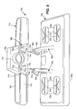
- The disclosed embodiments are disclosed more or less diagrammatically in the accompanying drawings, wherein:
- Fig. 1 is a rear perspective view of a vacuum cleaner head assembly made in accordance with this disclosure;
- Fig. 2 is a front perspective view of the vacuum cleaner head assembly shown in Fig. 1, without the electrostatic cloth attached thereto;
- Fig. 3 is a rear exploded perspective view of the vacuum cleaner head assembly as shown in Fig. 2;
- Fig. 4 is a side perspective view of the vacuum cleaner head assembly as shown in Figs. 2-3;
- Fig. 5 is a rear perspective view of a second embodiment of a vacuum cleaner head assembly made in accordance with this disclosure;
- Fig. 6 is a rear exploded perspective view of the vacuum cleaner head assembly shown in Fig. 5; and
- Figs. 7 and 8 are partial perspective views illustrating the latching mechanism between the vacuum head and secondary head of the assembly shown in Figs. 5 and 6.
-
- It should be understood that the drawings are not necessarily to scale and that the embodiments have been illustrated with diagrammatic representations and fragmentary views. In certain instances, details which are not necessary for an understanding of the disclosed embodiments or which render other details difficult to perceive may have been omitted. It should be understood that this disclosure is not necessarily limited to the particular embodiments illustrated herein.
- Figs. 1-4 illustrate a vacuum
cleaner head assembly 10 which includes avacuum head 11 detachably connected to asecondary head 12 which, in the embodiment disclosed in Figs. 1-4, provides support for acloth 13 and, more specifically, anelectrostatic cloth 13. Figs. 5-8 illustrate a slightly different embodiment of avacuum head assembly 10a using the same reference numerals used for the elements illustrated in Figs. 1-4 but with the subscript "a." - The
vacuum head 11 includes afront side 14 that is connected to arear side 15 by atop panel 16, all of which define a downwardly facing scoop for the collection of debris. Therear side 15 of thevacuum head 11 is connected to asuction hose port 17. In the embodiment shown in Figs. 1-4, therear side 15 andtop panel 16 of thevacuum head 11 includes a hollowupper extension 18 which, in turn, is connected to thesuction hose port 17. Theport suction hose 17 is then connected to a vacuum hose (not shown) which is connected to a vacuum pump (not shown). - The
secondary head 12 comprises a generally flat structure with ahorizontal bottom side 21 that faces the floor and a generally horizontaltop side 22. Thetop side 22 comprises a plurality of sockets shown at 23 which, in turn, each comprise amembrane 24 with one or more slits orcuts 25 disposed therein. The slits orcuts 25 in theflexible membrane 24 can releasably accommodate a side edge or other portion of thecloth 13 as shown in Fig. 1. All the consumer needs to do is simply press an edge portion of thecloth 13 through theslit 25 of themembrane 24 of eachsocket 23 to secure the cloth in place as shown in Fig. 1. - A key advantage of the
embodiment 10 shown in Figs. 1-4 (and theembodiment 10a of Figs. 5-8) is that thesecondary heads - Specifically, as best seen in Fig. 3, the
vacuum head 11 comprises a pair of space-apart brackets bracket groove groove corresponding tongue brackets secondary head 12. - From the lower position shown in Fig. 3 (see also Fig. 7 for the
embodiment 10a), the user aligns thebrackets secondary head 12 with thebrackets vacuum head 11. Then, the user moves theheads tongues grooves brackets assembly 10 assumes the position shown in Figs. 1, 2 and 4. - The
brackets secondary head 12 are also equipped withflexible latches latch lower leg corresponding bracket secondary head 12. Eachlower leg leg leg top surface corresponding bracket vacuum head 11 as best shown in Fig. 4. Preferably, thelatches brackets secondary heads secondary heads brackets - An injection molding process is the preferred manufacturing technique for both the
vacuum head 11 and thesecondary head 12 although other alternative techniques will be apparent to those skilled in the art. One preferred material of construction is polypropylene, but certain polyethylenes can be used as well. Other suitable materials include polyvinylchloride, polyethyleneterepthalata, polycarbonate and mixtures thereof. Also, thesecondary heads pad - Turning to Fig. 4, after the
tongues grooves forward legs brackets tongues grooves tongues grooves latches forward legs upper surfaces brackets secondary head 12 from thevacuum head 11, all the consumer needs to do is grab on to thefinger tabs arrows legs upper surfaces brackets vacuum head 11 upward, or a combination of the two movements. - Figs. 5-8 illustrate an
additional embodiment 10a with revisedbrackets vacuum cleaner head 11a and revisedbrackets secondary head 12a. Turning to Figs. 7 and 8, and referring only to theleft brackets bracket 31 a of thevacuum cleaner head 11a also includes a slot or groove shown in phantom at 33a. Thebracket 37a of thesecondary head 12a also includes atongue 35a which is received within thegroove 33a. Atop wall 71 a of thebracket 37a is received within theslot 72a of thebracket 31 a as shown in Fig. 8. As this happens, the forwardly extendingleg 47a rides up the rampedsurface 73a of thebracket 31a until it reaches its latching mechanism as shown in Fig. 8. As an additional guide, a wedge shapedwall 74a is provided on thevacuum cleaner head 11a to facilitate the alignment of thebrackets secondary head 12a with thebrackets vacuum cleaner head 11a. - Thus, an improved
vacuum head assembly 10 is provided whereby asecondary head 12 which carries anelectrostatic cloth 13 may be easily connected to and disconnected from avacuum head 11. - While only a single embodiment has been set forth and described, alternative embodiments and various modifications will apparent from the above description to those skilled in the art. These and other alternatives are considered equivalents in with the spirit and scope of this disclosure.
Claims (17)
- A vacuum cleaner head assembly comprising:a vacuum head comprising a front side and a rear side, the rear side of the vacuum head further comprising a pair of spaced apart brackets,the assembly further comprising a secondary head for accommodating a cloth, the secondary head comprising a pair of spaced apart brackets,the vacuum head brackets and secondary head brackets being detachably connectable together.
- The assembly of claim 1 wherein the brackets are detachably connected by a tongue-in-groove connection.
- The assembly of claim 2 wherein the assembly further comprising a pair of latches to secure the secondary head brackets to the vacuum head brackets when the secondary head bracket are connected to the vacuum head brackets by the tongue-in-groove connection.
- The assembly of claim 3 wherein one latch is connected to one of the secondary head brackets and the other latch is connected to the other of the secondary head brackets and the latches are flexibly biased into engagement with one of the vacuum head brackets when the tongues are received in the grooves.
- The assembly of claim 3 wherein one latch is connected to one of the vacuum head brackets and the other latch is connected to the other of the vacuum head brackets and the latches are flexibly biased into engagement with one of the secondary head brackets when the tongues are received in the grooves.
- The assembly of claim 1 wherein the vacuum head brackets are connected to the vacuum head with a suction hose port disposed therebetween.
- The assembly of claim 2 wherein the tongue-in-groove connection comprises each vacuum head bracket comprising a groove and each secondary head bracket comprising a tongue, the secondary head brackets being configured so the tongue of one of the secondary head brackets can be slidably received in the groove of one of the vacuum head brackets and the tongue of the other secondary head bracket can be slidably received in the groove of the other vacuum head bracket.
- The assembly of claim 2 wherein the tongue-in-groove connection comprises each vacuum head bracket comprising a tongue and each secondary head bracket comprising a groove, the secondary head brackets being configured so the groove of one of the secondary head brackets slidably receives the tongue of one of the vacuum head brackets and the groove of the other secondary head bracket slidably receives the tongue of the other vacuum head bracket.
- The assembly of claim 1 wherein the cloth is an electrostatic cloth.
- A vacuum cleaner head assembly comprising:a vacuum head comprising a front side and a rear side connected to a suction hose port, the rear side of the vacuum head further comprising a pair of spaced apart brackets,the assembly further comprising a secondary head for accommodating a cloth, the secondary head comprising a pair of spaced apart brackets,the vacuum head brackets and secondary head brackets being detachably connectable by a tongue-in-groove connection,the assembly further comprising a pair of latches to secure the secondary head brackets to the vacuum head brackets when the secondary head bracket are connected to the vacuum head brackets by the tongue-in-groove connection.
- The assembly of claim 10 wherein the vacuum head brackets are connected to the vacuum head with the suction hose port disposed therebetween.
- The assembly of claim 10 wherein the tongue-in-groove connection comprises each vacuum head bracket comprising a groove and each secondary head bracket comprising a tongue, the secondary head brackets being configured so the tongue of one of the secondary head brackets can be slidably received in the groove of one of the vacuum head brackets and the tongue of the other secondary head bracket can be slidably received in the groove of the other vacuum head bracket.
- The assembly of claim 12 wherein one latch is connected to one of the secondary head brackets and the other latch is connected to the other of the secondary head brackets and the latches are flexibly biased into engagement with one of the vacuum head brackets when the tongues are received in the grooves.
- The assembly of claim 10 wherein the tongue-in-groove connection comprises each vacuum head bracket comprising a tongue and each secondary head bracket comprising a groove, the secondary head brackets being configured so the groove of one of the secondary head brackets slidably receives the tongue of one of the vacuum head brackets and the groove of the other secondary head bracket slidably receives the tongue of the other vacuum head bracket.
- The assembly of claim 14 wherein one latch is connected to one of the vacuum head brackets and the other latch is connected to the other of the vacuum head brackets and the latches are flexibly biased into engagement with one of the secondary head brackets when the tongues are received in the grooves.
- The assembly of claim 10 wherein the cloth is an electrostatic cloth.
- A vacuum cleaner head assembly comprising:a vacuum head comprising a front side and a rear side connected to a suction hose port, the rear side of the vacuum head further comprising a pair of brackets spaced apart and connected to the rear side of the vacuum head on either side of the suction hose port,each vacuum head bracket comprising a slot,the assembly further comprising a secondary head for accommodating an electrostatic cloth, the secondary head comprising a pair of spaced apart brackets, each bracket of the secondary head comprising a tongue, the brackets of the secondary head being configured so the tongue of one of the secondary head brackets can be slidably received in the slot of one of the vacuum head brackets and the tongue of the other secondary head bracket can be slidably received in the slot of the other vacuum head bracket,the secondary head brackets each further comprising a latch to secure the secondary head brackets to the vacuum head brackets when the tongues of the secondary head bracket are received in the slots of the vacuum head brackets.
Applications Claiming Priority (2)
| Application Number | Priority Date | Filing Date | Title |
|---|---|---|---|
| US854011 | 1986-04-21 | ||
| US10/854,011 US7337494B2 (en) | 2004-05-26 | 2004-05-26 | Electrostatic cloth attachment for vacuum head |
Publications (3)
| Publication Number | Publication Date |
|---|---|
| EP1600092A2 true EP1600092A2 (en) | 2005-11-30 |
| EP1600092A3 EP1600092A3 (en) | 2009-12-02 |
| EP1600092B1 EP1600092B1 (en) | 2012-04-04 |
Family
ID=34941924
Family Applications (1)
| Application Number | Title | Priority Date | Filing Date |
|---|---|---|---|
| EP05290225A Expired - Lifetime EP1600092B1 (en) | 2004-05-26 | 2005-02-01 | Electrostatic cloth attachment for vacuum head |
Country Status (5)
| Country | Link |
|---|---|
| US (1) | US7337494B2 (en) |
| EP (1) | EP1600092B1 (en) |
| AU (1) | AU2005200427B2 (en) |
| CA (1) | CA2484129C (en) |
| MX (1) | MXPA04011032A (en) |
Cited By (11)
| Publication number | Priority date | Publication date | Assignee | Title |
|---|---|---|---|---|
| WO2008028761A1 (en) * | 2006-09-05 | 2008-03-13 | BSH Bosch und Siemens Hausgeräte GmbH | Hard floor nozzle |
| WO2010014367A1 (en) * | 2008-07-31 | 2010-02-04 | The Procter & Gamble Company | Head for a cleaning implement having a removable dirt bin |
| WO2010014366A1 (en) * | 2008-07-31 | 2010-02-04 | The Procter & Gamble Company | Unitary sheet and air filter for cleaning implement |
| WO2010014365A1 (en) * | 2008-07-31 | 2010-02-04 | The Procter & Gamble Company | Head for a cleaning implement |
| WO2014020303A1 (en) * | 2012-08-03 | 2014-02-06 | Dyson Technology Limited | A floor tool for a vacuum cleaning appliance |
| WO2014020304A1 (en) * | 2012-08-03 | 2014-02-06 | Dyson Technology Limited | A floor tool for a vacuum cleaning appliance |
| WO2015067920A1 (en) * | 2013-11-08 | 2015-05-14 | Techtronic Floor Care Technology Limited | Surface-cleaning apparatus |
| EP3207850A1 (en) * | 2016-02-18 | 2017-08-23 | Lg Electronics Inc. | Cleaner |
| US9907446B2 (en) | 2012-08-03 | 2018-03-06 | Dyson Technology Limited | Floor tool for a vacuum cleaning appliance |
| US20220386837A1 (en) * | 2021-05-31 | 2022-12-08 | Rushi Parikh | Universal accessory for enhancing floor cleaning and hair trapping for a plurality of vacuum devices |
| DE102021122305A1 (en) | 2021-08-27 | 2023-03-02 | Leifheit Aktiengesellschaft | Additional component for a floor cleaning device and floor cleaning device |
Families Citing this family (34)
| Publication number | Priority date | Publication date | Assignee | Title |
|---|---|---|---|---|
| JP3882191B2 (en) * | 2003-06-13 | 2007-02-14 | ツインバード工業株式会社 | Electric vacuum cleaner |
| US11612288B2 (en) | 2009-03-13 | 2023-03-28 | Omachron Intellectual Property Inc. | Surface cleaning apparatus |
| US9480373B2 (en) * | 2009-03-13 | 2016-11-01 | Omachron Intellectual Property Inc. | Surface cleaning apparatus |
| US8316499B2 (en) * | 2010-01-06 | 2012-11-27 | Evolution Robotics, Inc. | Apparatus for holding a cleaning sheet in a cleaning implement |
| KR101208552B1 (en) * | 2010-07-06 | 2012-12-06 | 엘지전자 주식회사 | A suction nozzle for vacuum cleaner |
| AU2011253852B2 (en) | 2010-12-15 | 2014-06-05 | Bissell Inc. | Suction nozzle with shuttling plate and converging debris paths |
| USD681899S1 (en) | 2011-08-22 | 2013-05-07 | Euro-Pro Operating Llc | Vacuum attachment |
| USD690888S1 (en) * | 2012-06-07 | 2013-10-01 | Karcher North America, Inc. | Fluid extraction tool |
| USD734576S1 (en) | 2014-09-25 | 2015-07-14 | Irobot Corporation | Robot |
| USD748878S1 (en) | 2014-09-25 | 2016-02-02 | Irobot Corporation | Robot |
| USD734907S1 (en) | 2014-09-25 | 2015-07-21 | Irobot Corporation | Robot |
| USD782139S1 (en) | 2014-09-25 | 2017-03-21 | Irobot Corporation | Cleaning pad |
| USD738585S1 (en) | 2014-09-25 | 2015-09-08 | Irobot Corporation | Robot |
| CA2971610C (en) * | 2014-12-19 | 2023-10-03 | Sharkninja Operating Llc | Vacuum cleaner attachment with floating cleaning element and surface cleaning apparatus including the same |
| USD833096S1 (en) | 2016-03-14 | 2018-11-06 | Irobot Corporation | Cleaning pad |
| US10807131B2 (en) * | 2016-05-02 | 2020-10-20 | Kewaunee Scientific Corporation | Laboratory hood with venturi effect air intake device for anti-turbulent air flow control |
| CN107960961A (en) * | 2016-10-20 | 2018-04-27 | 宝鸡银康机械设备有限公司 | Hand grabs tearing type electrostatic paper hair adsorbing set |
| US10869586B2 (en) | 2016-11-17 | 2020-12-22 | Karcher North America, Inc. | Portable vacuum and related accessories |
| EP3991624A1 (en) | 2017-09-11 | 2022-05-04 | SharkNinja Operating LLC | Cleaning device |
| US11426038B2 (en) * | 2017-09-11 | 2022-08-30 | Sharkninja Operating Llc | Cleaning device |
| EP3873314B1 (en) | 2018-11-01 | 2023-08-30 | SharkNinja Operating LLC | Cleaning device |
| US11426044B1 (en) | 2018-12-18 | 2022-08-30 | Sharkninja Operating Llc | Cleaning device |
| CN212853334U (en) | 2018-12-18 | 2021-04-02 | 尚科宁家运营有限公司 | Cleaning head and cleaning equipment |
| US11452414B2 (en) | 2019-10-31 | 2022-09-27 | Sharkninja Operating Llc | Replacement head for a vacuum |
| US11219345B2 (en) | 2019-10-31 | 2022-01-11 | Sharkninja Operating Llc | Replacement head for a vacuum |
| US10959584B1 (en) | 2019-10-31 | 2021-03-30 | Sharkninja Operating Llc | Replacement head for a vacuum |
| US11266283B2 (en) | 2019-10-31 | 2022-03-08 | Sharkninja Operating Llc | Replacement head for a vacuum |
| US11471019B2 (en) | 2020-02-14 | 2022-10-18 | Sharkninja Operating Llc | Cleaning device with lights |
| USD946223S1 (en) | 2020-02-14 | 2022-03-15 | Sharkninja Operating Llc | Cleaning device |
| USD946226S1 (en) | 2020-02-14 | 2022-03-15 | Sharkninja Operating Llc | Cleaning device |
| USD946843S1 (en) | 2020-02-14 | 2022-03-22 | Sharkninja Operating Llc | Cleaning device |
| USD946842S1 (en) | 2020-02-14 | 2022-03-22 | Sharkninja Operating Llc | Cleaning device |
| US11179014B2 (en) | 2020-02-19 | 2021-11-23 | Sharkninja Operating Llc | Cleaning device system and method for use |
| US10952580B1 (en) | 2020-02-19 | 2021-03-23 | Sharkninja Operating Llc | Cleaning device with rotatable head |
Citations (1)
| Publication number | Priority date | Publication date | Assignee | Title |
|---|---|---|---|---|
| GB2296426A (en) | 1994-12-31 | 1996-07-03 | Kwang Ju Electronics Co Ltd | A vacuum cleaner with damp cloth apparatus |
Family Cites Families (11)
| Publication number | Priority date | Publication date | Assignee | Title |
|---|---|---|---|---|
| US5241724A (en) * | 1990-12-14 | 1993-09-07 | Samsung Electronics Co., Ltd. | Vacuum cleaner having the function of wet wiping rag |
| US5557823A (en) * | 1995-05-26 | 1996-09-24 | Jma & Associates | Vacuum cleaner attachment |
| JPH0938011A (en) * | 1995-08-02 | 1997-02-10 | Eisaku Ohara | Cleaner nozzle with mop |
| JPH1014829A (en) * | 1996-07-09 | 1998-01-20 | Sanyo Electric Co Ltd | Suction tool for electric vacuum cleaner |
| IT1307839B1 (en) * | 1999-02-03 | 2001-11-19 | Douss Line S R L | A BRUSH FOR THE CLEANING OF FLOORS AND / OR CARPETS EQUIPPED WITH A SUCTION DEVICE AND A GENERATOR AND DEVICE |
| KR100640920B1 (en) * | 2000-05-12 | 2006-11-02 | 엘지전자 주식회사 | Inlet for vacuum cleaner |
| US7013528B2 (en) * | 2002-01-28 | 2006-03-21 | Bissell Homecare, Inc. | Floor cleaner with dusting |
| US7137169B2 (en) * | 2003-01-10 | 2006-11-21 | Royal Appliance Mfg. Co. | Vacuum cleaner with cleaning pad |
| US6966098B2 (en) * | 2003-02-27 | 2005-11-22 | Matsushita Electric Industrial Co., Ltd. | Cleaner |
| US7293322B2 (en) * | 2003-10-09 | 2007-11-13 | Royal Appliance Mfg. Co. | Cleaning attachment for vacuum cleaner |
| JP5325471B2 (en) * | 2007-07-06 | 2013-10-23 | 株式会社半導体エネルギー研究所 | Method for manufacturing light emitting device |
-
2004
- 2004-05-26 US US10/854,011 patent/US7337494B2/en not_active Expired - Lifetime
- 2004-10-06 CA CA2484129A patent/CA2484129C/en not_active Expired - Fee Related
- 2004-11-05 MX MXPA04011032A patent/MXPA04011032A/en active IP Right Grant
-
2005
- 2005-02-01 EP EP05290225A patent/EP1600092B1/en not_active Expired - Lifetime
- 2005-02-02 AU AU2005200427A patent/AU2005200427B2/en not_active Ceased
Patent Citations (1)
| Publication number | Priority date | Publication date | Assignee | Title |
|---|---|---|---|---|
| GB2296426A (en) | 1994-12-31 | 1996-07-03 | Kwang Ju Electronics Co Ltd | A vacuum cleaner with damp cloth apparatus |
Cited By (21)
| Publication number | Priority date | Publication date | Assignee | Title |
|---|---|---|---|---|
| WO2008028761A1 (en) * | 2006-09-05 | 2008-03-13 | BSH Bosch und Siemens Hausgeräte GmbH | Hard floor nozzle |
| WO2010014367A1 (en) * | 2008-07-31 | 2010-02-04 | The Procter & Gamble Company | Head for a cleaning implement having a removable dirt bin |
| WO2010014366A1 (en) * | 2008-07-31 | 2010-02-04 | The Procter & Gamble Company | Unitary sheet and air filter for cleaning implement |
| WO2010014365A1 (en) * | 2008-07-31 | 2010-02-04 | The Procter & Gamble Company | Head for a cleaning implement |
| CN102112031B (en) * | 2008-07-31 | 2013-08-21 | 宝洁公司 | Unitary sheet and air filter for cleaning implement |
| WO2014020303A1 (en) * | 2012-08-03 | 2014-02-06 | Dyson Technology Limited | A floor tool for a vacuum cleaning appliance |
| WO2014020304A1 (en) * | 2012-08-03 | 2014-02-06 | Dyson Technology Limited | A floor tool for a vacuum cleaning appliance |
| US9907446B2 (en) | 2012-08-03 | 2018-03-06 | Dyson Technology Limited | Floor tool for a vacuum cleaning appliance |
| US9282864B2 (en) | 2012-08-03 | 2016-03-15 | Dyson Technology Limited | Floor tool for a vacuum cleaning appliance |
| AU2013298314B2 (en) * | 2012-08-03 | 2016-04-14 | Dyson Technology Limited | A floor tool for a vacuum cleaning appliance |
| CN105813531A (en) * | 2013-11-08 | 2016-07-27 | 创科地板护理技术有限公司 | surface cleaning device |
| US9591960B2 (en) | 2013-11-08 | 2017-03-14 | Techtronic Floor Care Technology Limited | Surface-cleaning apparatus |
| WO2015067920A1 (en) * | 2013-11-08 | 2015-05-14 | Techtronic Floor Care Technology Limited | Surface-cleaning apparatus |
| EP3207850A1 (en) * | 2016-02-18 | 2017-08-23 | Lg Electronics Inc. | Cleaner |
| CN107088023A (en) * | 2016-02-18 | 2017-08-25 | Lg电子株式会社 | Dust catcher |
| EP3412187A1 (en) * | 2016-02-18 | 2018-12-12 | LG Electronics Inc. | Cleaner |
| CN107088023B (en) * | 2016-02-18 | 2019-09-03 | Lg电子株式会社 | Dust catcher |
| US10849474B2 (en) | 2016-02-18 | 2020-12-01 | Lg Electronics Inc. | Cleaner |
| US20220386837A1 (en) * | 2021-05-31 | 2022-12-08 | Rushi Parikh | Universal accessory for enhancing floor cleaning and hair trapping for a plurality of vacuum devices |
| DE102021122305A1 (en) | 2021-08-27 | 2023-03-02 | Leifheit Aktiengesellschaft | Additional component for a floor cleaning device and floor cleaning device |
| EP4144273A1 (en) | 2021-08-27 | 2023-03-08 | Leifheit AG | Add-on component for a floor cleaning device and floor cleaning device |
Also Published As
| Publication number | Publication date |
|---|---|
| EP1600092A3 (en) | 2009-12-02 |
| AU2005200427A1 (en) | 2005-12-15 |
| US7337494B2 (en) | 2008-03-04 |
| EP1600092B1 (en) | 2012-04-04 |
| CA2484129C (en) | 2012-06-19 |
| US20050262661A1 (en) | 2005-12-01 |
| MXPA04011032A (en) | 2005-11-30 |
| AU2005200427B2 (en) | 2011-03-03 |
| CA2484129A1 (en) | 2005-11-26 |
Similar Documents
| Publication | Publication Date | Title |
|---|---|---|
| CA2484129C (en) | Electrostatic cloth attachment for vacuum head | |
| CA2413401C (en) | Convertible vacuum cleaner | |
| US7937802B2 (en) | Vacuum cleaner for use in both upright form and canister form | |
| KR101491002B1 (en) | vacuum cleaner | |
| CN105979839B (en) | Vacuum cleaner with removable canister assembly | |
| GB2403132A (en) | Tilting vacuum cleaner with removable body portion | |
| US11375862B2 (en) | Cleaner stand and cleaning apparatus having the same | |
| GB2504675A (en) | Vacuum appliance floor tool pivot arrangement | |
| GB2504678A (en) | Vacuum appliance floor tool with removable pad and rolling arrangement | |
| GB2504674A (en) | Vacuum appliance floor tool clamping arrangement | |
| GB2504676A (en) | Vacuum appliance floor tool with conduit access arrangement | |
| CA2843333C (en) | Vacuum cleaner with accessory tool assembly | |
| EP3030125B1 (en) | Vacuum cleaner including a removable handle assembly | |
| US20090007368A1 (en) | Upright vacuum cleaner having wet cleaning function | |
| US20030145425A1 (en) | Multi-function vacuum cleaner accessory | |
| US20090044359A1 (en) | Suction brush having hair removal unit for vacuum cleaner | |
| JP2009061209A (en) | Suction tool and vacuum cleaner | |
| JPH0489017A (en) | Vacuum cleaner | |
| CN216823280U (en) | Surface cleaning apparatus | |
| JP2025084248A (en) | Suction port body and vacuum cleaner | |
| WO2025229036A1 (en) | A surface cleaning apparatus | |
| KR101055066B1 (en) | Nozzle of vacuum cleaner | |
| GB2434308A (en) | Integral accessory support arrangement on vacuum cleaner handle | |
| JP2025084250A (en) | Suction port body and vacuum cleaner | |
| JP2025084249A (en) | Suction port body and vacuum cleaner |
Legal Events
| Date | Code | Title | Description |
|---|---|---|---|
| PUAI | Public reference made under article 153(3) epc to a published international application that has entered the european phase |
Free format text: ORIGINAL CODE: 0009012 |
|
| AK | Designated contracting states |
Kind code of ref document: A2 Designated state(s): AT BE BG CH CY CZ DE DK EE ES FI FR GB GR HU IE IS IT LI LT LU MC NL PL PT RO SE SI SK TR |
|
| AX | Request for extension of the european patent |
Extension state: AL BA HR LV MK YU |
|
| PUAL | Search report despatched |
Free format text: ORIGINAL CODE: 0009013 |
|
| AK | Designated contracting states |
Kind code of ref document: A3 Designated state(s): AT BE BG CH CY CZ DE DK EE ES FI FR GB GR HU IE IS IT LI LT LU MC NL PL PT RO SE SI SK TR |
|
| AX | Request for extension of the european patent |
Extension state: AL BA HR LV MK YU |
|
| 17P | Request for examination filed |
Effective date: 20100209 |
|
| 17Q | First examination report despatched |
Effective date: 20100428 |
|
| AKX | Designation fees paid |
Designated state(s): CH DE FR GB IE IT LI |
|
| GRAP | Despatch of communication of intention to grant a patent |
Free format text: ORIGINAL CODE: EPIDOSNIGR1 |
|
| GRAS | Grant fee paid |
Free format text: ORIGINAL CODE: EPIDOSNIGR3 |
|
| GRAA | (expected) grant |
Free format text: ORIGINAL CODE: 0009210 |
|
| AK | Designated contracting states |
Kind code of ref document: B1 Designated state(s): CH DE FR GB IE IT LI |
|
| REG | Reference to a national code |
Ref country code: GB Ref legal event code: FG4D |
|
| REG | Reference to a national code |
Ref country code: CH Ref legal event code: EP |
|
| REG | Reference to a national code |
Ref country code: IE Ref legal event code: FG4D |
|
| REG | Reference to a national code |
Ref country code: DE Ref legal event code: R096 Ref document number: 602005033482 Country of ref document: DE Effective date: 20120531 |
|
| REG | Reference to a national code |
Ref country code: CH Ref legal event code: NV Representative=s name: ISLER & PEDRAZZINI AG |
|
| PLBE | No opposition filed within time limit |
Free format text: ORIGINAL CODE: 0009261 |
|
| STAA | Information on the status of an ep patent application or granted ep patent |
Free format text: STATUS: NO OPPOSITION FILED WITHIN TIME LIMIT |
|
| 26N | No opposition filed |
Effective date: 20130107 |
|
| REG | Reference to a national code |
Ref country code: DE Ref legal event code: R097 Ref document number: 602005033482 Country of ref document: DE Effective date: 20130107 |
|
| REG | Reference to a national code |
Ref country code: FR Ref legal event code: PLFP Year of fee payment: 11 |
|
| REG | Reference to a national code |
Ref country code: FR Ref legal event code: PLFP Year of fee payment: 12 |
|
| REG | Reference to a national code |
Ref country code: FR Ref legal event code: PLFP Year of fee payment: 13 |
|
| PGFP | Annual fee paid to national office [announced via postgrant information from national office to epo] |
Ref country code: CH Payment date: 20170214 Year of fee payment: 13 |
|
| PGFP | Annual fee paid to national office [announced via postgrant information from national office to epo] |
Ref country code: IE Payment date: 20170209 Year of fee payment: 13 |
|
| PGFP | Annual fee paid to national office [announced via postgrant information from national office to epo] |
Ref country code: IT Payment date: 20170221 Year of fee payment: 13 |
|
| REG | Reference to a national code |
Ref country code: FR Ref legal event code: PLFP Year of fee payment: 14 |
|
| REG | Reference to a national code |
Ref country code: CH Ref legal event code: PL |
|
| REG | Reference to a national code |
Ref country code: IE Ref legal event code: MM4A |
|
| PG25 | Lapsed in a contracting state [announced via postgrant information from national office to epo] |
Ref country code: CH Free format text: LAPSE BECAUSE OF NON-PAYMENT OF DUE FEES Effective date: 20180228 Ref country code: LI Free format text: LAPSE BECAUSE OF NON-PAYMENT OF DUE FEES Effective date: 20180228 |
|
| PG25 | Lapsed in a contracting state [announced via postgrant information from national office to epo] |
Ref country code: IE Free format text: LAPSE BECAUSE OF NON-PAYMENT OF DUE FEES Effective date: 20180201 |
|
| PG25 | Lapsed in a contracting state [announced via postgrant information from national office to epo] |
Ref country code: IT Free format text: LAPSE BECAUSE OF NON-PAYMENT OF DUE FEES Effective date: 20180201 |
|
| PGFP | Annual fee paid to national office [announced via postgrant information from national office to epo] |
Ref country code: FR Payment date: 20181213 Year of fee payment: 15 |
|
| PGFP | Annual fee paid to national office [announced via postgrant information from national office to epo] |
Ref country code: DE Payment date: 20190122 Year of fee payment: 15 Ref country code: GB Payment date: 20190130 Year of fee payment: 15 |
|
| REG | Reference to a national code |
Ref country code: DE Ref legal event code: R119 Ref document number: 602005033482 Country of ref document: DE |
|
| GBPC | Gb: european patent ceased through non-payment of renewal fee |
Effective date: 20200201 |
|
| PG25 | Lapsed in a contracting state [announced via postgrant information from national office to epo] |
Ref country code: FR Free format text: LAPSE BECAUSE OF NON-PAYMENT OF DUE FEES Effective date: 20200229 Ref country code: DE Free format text: LAPSE BECAUSE OF NON-PAYMENT OF DUE FEES Effective date: 20200901 Ref country code: GB Free format text: LAPSE BECAUSE OF NON-PAYMENT OF DUE FEES Effective date: 20200201 |