EP1599984B1 - Frame synchronization and scrambling code identification in wireless communications systems and methods therefor - Google Patents
Frame synchronization and scrambling code identification in wireless communications systems and methods therefor Download PDFInfo
- Publication number
- EP1599984B1 EP1599984B1 EP04714684A EP04714684A EP1599984B1 EP 1599984 B1 EP1599984 B1 EP 1599984B1 EP 04714684 A EP04714684 A EP 04714684A EP 04714684 A EP04714684 A EP 04714684A EP 1599984 B1 EP1599984 B1 EP 1599984B1
- Authority
- EP
- European Patent Office
- Prior art keywords
- signal
- correlating
- information
- storing
- boundary information
- Prior art date
- Legal status (The legal status is an assumption and is not a legal conclusion. Google has not performed a legal analysis and makes no representation as to the accuracy of the status listed.)
- Expired - Lifetime
Links
- 238000000034 method Methods 0.000 title claims description 28
- 238000004891 communication Methods 0.000 title claims description 21
- 230000000875 corresponding effect Effects 0.000 description 8
- 238000010586 diagram Methods 0.000 description 8
- 230000002596 correlated effect Effects 0.000 description 5
- 238000001228 spectrum Methods 0.000 description 2
- 230000010267 cellular communication Effects 0.000 description 1
- 230000001413 cellular effect Effects 0.000 description 1
- 238000001514 detection method Methods 0.000 description 1
- 230000000694 effects Effects 0.000 description 1
- 238000005562 fading Methods 0.000 description 1
- 238000001914 filtration Methods 0.000 description 1
- 230000010354 integration Effects 0.000 description 1
- 238000010295 mobile communication Methods 0.000 description 1
- 238000012986 modification Methods 0.000 description 1
- 230000004048 modification Effects 0.000 description 1
Images

Classifications
-
- H—ELECTRICITY
- H04—ELECTRIC COMMUNICATION TECHNIQUE
- H04B—TRANSMISSION
- H04B1/00—Details of transmission systems, not covered by a single one of groups H04B3/00 - H04B13/00; Details of transmission systems not characterised by the medium used for transmission
- H04B1/69—Spread spectrum techniques
- H04B1/707—Spread spectrum techniques using direct sequence modulation
- H04B1/7073—Synchronisation aspects
- H04B1/70735—Code identification
-
- H—ELECTRICITY
- H04—ELECTRIC COMMUNICATION TECHNIQUE
- H04B—TRANSMISSION
- H04B1/00—Details of transmission systems, not covered by a single one of groups H04B3/00 - H04B13/00; Details of transmission systems not characterised by the medium used for transmission
- H04B1/69—Spread spectrum techniques
- H04B1/707—Spread spectrum techniques using direct sequence modulation
- H04B1/709—Correlator structure
Definitions
- the present disclosure relates generally to wireless communications, and more particularly to frame synchronization and scrambling code determination in code division multiple access (CDMA) communication systems, for example, in 3 rd Generation (3G) Universal Mobile Telecommunications System (UMTS) communications systems, including mobile wireless communications devices and methods therefor.
- CDMA code division multiple access
- 3G 3 rd Generation
- UMTS Universal Mobile Telecommunications System
- 3G UMTS communication systems significant time is required for mobile stations, or subscriber devices, to search for neighbor pilot signals from neighbor list information provided by network base stations in a system information broadcast or similar message.
- UMTS frame synchronization and scrambling code identification procedures are performed at separate signal processing stages, which generally require operation of the radio frequency (RF) receiver for extended time periods, including operation during standby mode, which represents more than an insubstantial drain on the battery.
- RF radio frequency
- Stage 1 slot boundaries of the primary synchronization channel (PSCH) of received neighbor signals are determined.
- frame synchronization is performed by correlating several slots of the secondary synchronization channel (SSCH) with each of 16 secondary synchronization codes (SSC), thus permitting frame boundary determination and Group Code identification, from which a corresponding set of scrambling codes may be determined.
- SSCH secondary synchronization channel
- SSC secondary synchronization codes
- frame synchronization requires correlation over at least 3 slots, but in practice the correlation may occur over 15 or more slots.
- Frame synchronization must be performed for each slot boundary identified at Stage 1 processing.
- base station selection occurs based upon the scrambling codes identified in Stage 2.
- the existing frame synchronization procedure produces many false results and has a low detection probability, partly because the SSCH channel is a weak signal. Also, since the SSCH channel may be correlated only for 256 chips per slot, correlation over multiple slots is usually required, thus prolonging the time during which the RF receiver must operate. The existing frame synchronization process is thus relatively inefficient, particularly during standby mode operation when the RF receiver would otherwise be inoperative.
- the disclosure pertains generally to methods for frame synchronization and scrambling code identification in mobile wireless communications devices operating in spread spectrum communications systems, for example, in mobile subscriber devices communicating in CDMA communications networks.
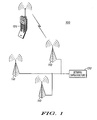
- FIG. 1 illustrates a wireless communications system 100 including a CDMA cellular communications network, for example, a 3 rd Generation (3G) Universal Mobile Telecommunications System (UMTS) communications system.
- the network generally comprises a plurality of base station transceivers 110 having corresponding overlapping cellular areas for supporting communications of mobile wireless communications subscriber devices, or user equipment (UE), 120 in the network.
- the communications network also includes other network infrastructure, known by those of ordinary skill in the art, indicated schematically in FIG. 1 at block 130.
- mobile subscriber devices for example, UE 120, in the communications network receive pilot and synchronization channel information from each of the neighboring base station transceivers 110.
- Each base station has a unique pilot signal, which may be distinguished from other pilot signals by its scrambling code, for example, a long scrambling code.
- the subscriber device must generally identify the neighboring base station pilot signals, which are used by the subscriber device to identify the presence of the network, for system acquisition, for demodulation of the synchronization, paging and traffic channels, and for handoffs.
- the disclosure generally concerns methods for determining frame boundary information and/or identifying a long scrambling code associated with a particular cell. These and other aspects of the disclosure are discussed more fully below.
- Spread spectrum based subscriber devices for example, UMTS UE, are generally capable of generating scrambling code information, or the scrambling code information is stored thereon, for frame synchronization, as is known generally by those of ordinary skill in the art.
- the scrambling code information corresponds, for example, to long scrambling codes associated with corresponding neighboring cells.
- subscriber devices are provided with neighbor cell information in a list provided in a System Information Block (SIB) of a Broadcast Channel (BCH).
- SIB System Information Block
- BCH Broadcast Channel
- RTD Reference Time Difference
- CPICH Common Pilot Channels
- CPICH Common Pilot Channels
- This information may be provided, for example, in the System Information Block of a Broadcast Channel in UMTS communication networks.
- the (RTD) information may be useful for extending the battery life of subscriber devices.
- frame timing information may or may not be known by the subscriber device.
- FIG. 2 is an exemplary process flow diagram 200 for neighbor cell frame synchronization by a subscriber device.
- the subscriber device receives signals from neighboring base stations.
- FIG. 3 illustrates exemplary radio frame timing and exemplary access slot timing information of downlink physical channels transmitted from exemplary UMTS network base stations.
- the UMTS signal has a 10 ms frame structure. Each frame comprises 15 slots, indicated as Slot 0 - Slot 14 in FIG. 3 .
- the exemplary UMTS signal includes a Primary Synchronization Channel (PSCH), a Secondary Synchronization Channel (SSCH), a Common Pilot Channel (CPICH), and a Dedicated Channel (DCH), all of which are illustrated schematically in FIG. 3 .
- PSCH Primary Synchronization Channel
- SSCH Secondary Synchronization Channel
- CPICH Common Pilot Channel
- DCH Dedicated Channel
- the subscriber device determines slot boundary information of the signal received.
- the slot boundary information generally includes the identification of at least one slot boundary, but more generally multiple slot boundaries are identified.
- the slot boundary information is essentially timing information.
- Each neighbor cell generally has a corresponding slot boundary, although multi-path effects may produce multiple slot boundaries for a particular cell. Slot boundary information for other neighbor cells may not be present because the corresponding signal strength is below a specified threshold.
- slot boundary information is determined from a Primary Synchronization Channel (PSCH) of received neighbor cell signals, for example, by conventional Stage 1 signal processing.
- PSCH Primary Synchronization Channel
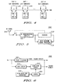
- FIG. 4 illustrates slot boundaries identified in Stage 1 signal processing. At least one and generally several slot boundaries are identified for each slot. In FIG. 4 , groupings of slot boundaries for each slot are identified as 410, 420, ... etc. for Slot 0, Slot 1 ... Slot 14, respectively. Generally the signal amplitude corresponding to the slot boundaries varies, depending on signal strength and only those having amplitudes above a specified threshold are considered for frame boundary and/or scrambling code determination. In FIG. 4 , each slot boundary corresponds generally to a neighbor cell and has a corresponding time offset based on its position along the time axis.
- FIG. 5 is a partial schematic block diagram of mobile communications device RF receiver and signal processing circuits 500 comprising generally radio down-converting circuitry 510 for providing basband signals to a searcher 520 and to a baseband processor 530.
- the down-converting circuitry is coupled to an antenna 540 by filtering and analog to digital converter circuits, which are known generally but not illustrated.
- FIG. 6 is a schematic block diagram of an exemplary searcher circuit 600 comprising generally a Stage 1 searcher 610 for performing Stage 1 signal processing as discussed above.
- frame boundary information and or a particular scrambling code is determined by correlating the signal with the scrambling code information based on the slot boundary information determined at block 220.
- the particular scrambling code is, for example, that associated with a particular corresponding cell.
- the correlation process occurs by aligning scrambling code information relative to the received signal based upon the slot boundary information before correlating the signal and the scrambling codes.
- the slot boundary information includes time-offset information, which is used to align the scrambling codes relative to the received signal, or portion thereof, for the correlation process, as discussed more fully below. For each slot boundary, correlation between the received signal and a scrambling code is performed at each of the several possible frame boundaries.
- FIG. 4 is a schematic illustration of an exemplary correlation process.
- neighbor cell scrambling codes Codes 1-N
- correlation between the received signal and a scrambling code is performed at each of fifteen (15) possible frame boundaries. It is unnecessary to use or first determine frame boundary information and/or scrambling group code information prior to determining the scrambling codes.
- the correlation process yields the frame boundary information and particular scrambling code information substantially simultaneously.
- the Stage 1 searcher provides the slot boundary information determined during the Stage 1 processing to a controller 620.
- the controller provides scrambling code information, for example, long scrambling codes, generated by a code generator 630 to a correlator circuit 640 based on the slot boundary information determined by the Stage 1 searcher, as discussed above.
- the correlator circuit 640 determines the frame boundary information and/or scrambling code information by correlating the received signal and the scrambling codes, as discussed above.
- scrambling codes may be identified without using frame boundary information or scrambling code group information.
- the scrambling code information is correlated with a continuous signal.
- the scrambling code information is correlated with the Common Pilot Channel (CPICH) illustrated in FIG. 3 , although other signals may be used in other embodiments.
- CPICH Common Pilot Channel
- the subscriber device stores a portion of the received signal, for example, a portion of the Common Pilot Channel (CPICH), and then de-energizes the RF receiver, whereupon the correlation is performed using the stored signal portion without continuing operation of the radio receiver.
- CPICH Common Pilot Channel
- FIG. 6 illustrates an input buffer 650 for storing the received signal portion, which is provided to the correlator circuit for correlation with the scrambling codes.
- the RF receiver is disabled upon actuation of a switch by the searcher 520 upon receipt and storage of the signal portion in a buffer.
- the controller 620 de-energizes the RF receiver circuits.
- information for less than one complete frame for example, less than one of the 10 ms frames of the exemplary UMTS signal illustrated in FIG. 3 , is stored in the buffer.
- information for a single slot or not substantially more than a single slot of a frame is stored in the buffer.
- the stored portion of the received signal includes page indication information for the subscriber device searching the pilot signals.
- the signal is received at block 710 and Stage 1 slot boundary information is determined at block 720.
- a portion of the received signal for example, the continuous Common Pilot Channel (CPICH) signal is captured in memory for subsequent correlation with the scrambling codes.
- CPICH Common Pilot Channel
- less than one complete frame of information is stored in the buffer, and in other embodiments information for a single slot is stored in the buffer.
- the slot boundary information may be obtained from the stored signal portion, though in other embodiments determination of the slot boundaries during Stage 1 processing occurs prior to storage of the signal portion or partially concurrently with the signal storage operation.
- the stored portion of the signal includes paging information for the subscriber device, thereby eliminating the need to re-energize the receiver to obtain page indicator information.
- the radio circuits are de-energized, thus reducing unnecessary power consumption associated with operation of the RF receiver during the correlation process. Determination of the frame boundary information and/or particular scrambling code information is performed by correlating the stored signal portion with the scrambling codes at block 750, as discussed above, while the radio circuit is de-energized.
- the radio circuit power ON time can be reduced from on the order of 10 ms (required for conventional Stage 2 and Stage 3 processing) to less than 1 ms, when using the synchronization process described above, substantially reducing charge drawn from the battery.
- the correlated information is preferably integrated as long as is required to determine the frame boundary and/or scrambling code information
- the correlation of the common pilot channel, CPICH, with the scrambling codes permits the integration.
Landscapes
- Engineering & Computer Science (AREA)
- Computer Networks & Wireless Communication (AREA)
- Signal Processing (AREA)
- Mobile Radio Communication Systems (AREA)
- Synchronisation In Digital Transmission Systems (AREA)
Description
- The present disclosure relates generally to wireless communications, and more particularly to frame synchronization and scrambling code determination in code division multiple access (CDMA) communication systems, for example, in 3rd Generation (3G) Universal Mobile Telecommunications System (UMTS) communications systems, including mobile wireless communications devices and methods therefor.
- In 3G UMTS communication systems, significant time is required for mobile stations, or subscriber devices, to search for neighbor pilot signals from neighbor list information provided by network base stations in a system information broadcast or similar message.
- Presently, when searching for neighbor pilot signals, UMTS frame synchronization and scrambling code identification procedures are performed at separate signal processing stages, which generally require operation of the radio frequency (RF) receiver for extended time periods, including operation during standby mode, which represents more than an insubstantial drain on the battery.
- At
Stage 1 signal processing, slot boundaries of the primary synchronization channel (PSCH) of received neighbor signals are determined. Subsequently, at the Stage 2 processing, frame synchronization is performed by correlating several slots of the secondary synchronization channel (SSCH) with each of 16 secondary synchronization codes (SSC), thus permitting frame boundary determination and Group Code identification, from which a corresponding set of scrambling codes may be determined. In theory, assuming no noise or fading, frame synchronization requires correlation over at least 3 slots, but in practice the correlation may occur over 15 or more slots. Frame synchronization must be performed for each slot boundary identified atStage 1 processing. At Stage 3 processing, base station selection occurs based upon the scrambling codes identified in Stage 2. - The existing frame synchronization procedure produces many false results and has a low detection probability, partly because the SSCH channel is a weak signal. Also, since the SSCH channel may be correlated only for 256 chips per slot, correlation over multiple slots is usually required, thus prolonging the time during which the RF receiver must operate. The existing frame synchronization process is thus relatively inefficient, particularly during standby mode operation when the RF receiver would otherwise be inoperative.
- The various aspects, features and advantages of the disclosure will become more fully apparent to those having ordinary skill in the art upon careful consideration of the following Detailed Description of the Disclosure and the accompanying drawings described below.
-
-
FIG. 1 is an exemplary communications system, including network infrastructure and a subscriber device. -
FIG. 2 is an exemplary frame synchronization process flow diagram. -
FIG. 3 illustrates radio frame and access slot timing of radio downlink physical channels. -
FIG. 4 is a schematic illustration of slot boundary and the scrambling code information. -
FIG. 5 is a partial schematic block diagram of radio RF receiver and signal processing circuits. -
FIG. 6 is a partial schematic block diagram of a signal searcher. -
FIG. 7 is an alternative frame synchronization process flow diagram. - The disclosure pertains generally to methods for frame synchronization and scrambling code identification in mobile wireless communications devices operating in spread spectrum communications systems, for example, in mobile subscriber devices communicating in CDMA communications networks.
-
FIG. 1 illustrates awireless communications system 100 including a CDMA cellular communications network, for example, a 3rd Generation (3G) Universal Mobile Telecommunications System (UMTS) communications system. The network generally comprises a plurality ofbase station transceivers 110 having corresponding overlapping cellular areas for supporting communications of mobile wireless communications subscriber devices, or user equipment (UE), 120 in the network. The communications network also includes other network infrastructure, known by those of ordinary skill in the art, indicated schematically inFIG. 1 atblock 130. - In
FIG. 1 , mobile subscriber devices, for example, UE 120, in the communications network receive pilot and synchronization channel information from each of the neighboringbase station transceivers 110. Each base station has a unique pilot signal, which may be distinguished from other pilot signals by its scrambling code, for example, a long scrambling code. The subscriber device must generally identify the neighboring base station pilot signals, which are used by the subscriber device to identify the presence of the network, for system acquisition, for demodulation of the synchronization, paging and traffic channels, and for handoffs. - The disclosure generally concerns methods for determining frame boundary information and/or identifying a long scrambling code associated with a particular cell. These and other aspects of the disclosure are discussed more fully below.
- Spread spectrum based subscriber devices, for example, UMTS UE, are generally capable of generating scrambling code information, or the scrambling code information is stored thereon, for frame synchronization, as is known generally by those of ordinary skill in the art. The scrambling code information corresponds, for example, to long scrambling codes associated with corresponding neighboring cells. In UMTS networks, subscriber devices are provided with neighbor cell information in a list provided in a System Information Block (SIB) of a Broadcast Channel (BCH).
- In some networks, operators optionally provide Reference Time Difference (RTD) information between the Common Pilot Channels (CPICH) of neighboring cells and the serving cell. This information may be provided, for example, in the System Information Block of a Broadcast Channel in UMTS communication networks. The (RTD) information may be useful for extending the battery life of subscriber devices. Thus generally during frame synchronization, frame timing information may or may not be known by the subscriber device.
-
FIG. 2 is an exemplary process flow diagram 200 for neighbor cell frame synchronization by a subscriber device. InFIG. 2 , atblock 210, the subscriber device receives signals from neighboring base stations.FIG. 3 illustrates exemplary radio frame timing and exemplary access slot timing information of downlink physical channels transmitted from exemplary UMTS network base stations. The UMTS signal has a 10 ms frame structure. Each frame comprises 15 slots, indicated as Slot 0 -Slot 14 inFIG. 3 . The exemplary UMTS signal includes a Primary Synchronization Channel (PSCH), a Secondary Synchronization Channel (SSCH), a Common Pilot Channel (CPICH), and a Dedicated Channel (DCH), all of which are illustrated schematically inFIG. 3 . - In
FIG. 2 , atblock 220, the subscriber device determines slot boundary information of the signal received. The slot boundary information generally includes the identification of at least one slot boundary, but more generally multiple slot boundaries are identified. The slot boundary information is essentially timing information. Each neighbor cell generally has a corresponding slot boundary, although multi-path effects may produce multiple slot boundaries for a particular cell. Slot boundary information for other neighbor cells may not be present because the corresponding signal strength is below a specified threshold. In one mode of operation, slot boundary information is determined from a Primary Synchronization Channel (PSCH) of received neighbor cell signals, for example, byconventional Stage 1 signal processing. -
FIG. 4 illustrates slot boundaries identified inStage 1 signal processing. At least one and generally several slot boundaries are identified for each slot. InFIG. 4 , groupings of slot boundaries for each slot are identified as 410, 420, ... etc. for Slot 0,Slot 1 ...Slot 14, respectively. Generally the signal amplitude corresponding to the slot boundaries varies, depending on signal strength and only those having amplitudes above a specified threshold are considered for frame boundary and/or scrambling code determination. InFIG. 4 , each slot boundary corresponds generally to a neighbor cell and has a corresponding time offset based on its position along the time axis. -
FIG. 5 is a partial schematic block diagram of mobile communications device RF receiver andsignal processing circuits 500 comprising generally radio down-convertingcircuitry 510 for providing basband signals to asearcher 520 and to abaseband processor 530. The down-converting circuitry is coupled to anantenna 540 by filtering and analog to digital converter circuits, which are known generally but not illustrated.FIG. 6 is a schematic block diagram of anexemplary searcher circuit 600 comprising generally aStage 1searcher 610 for performingStage 1 signal processing as discussed above. - In
FIG. 2 , atblock 230, frame boundary information and or a particular scrambling code is determined by correlating the signal with the scrambling code information based on the slot boundary information determined atblock 220. The particular scrambling code is, for example, that associated with a particular corresponding cell. - The correlation process occurs by aligning scrambling code information relative to the received signal based upon the slot boundary information before correlating the signal and the scrambling codes. More particularly, the slot boundary information includes time-offset information, which is used to align the scrambling codes relative to the received signal, or portion thereof, for the correlation process, as discussed more fully below. For each slot boundary, correlation between the received signal and a scrambling code is performed at each of the several possible frame boundaries.
-
FIG. 4 is a schematic illustration of an exemplary correlation process. For each slot boundary, neighbor cell scrambling codes, Codes 1-N, are each aligned and correlated with the received signal, at each of the several possible frame boundaries, to determine the desired frame boundary information and/or to identify a particular scrambling code. InFIG. 4 , for each slot boundary, correlation between the received signal and a scrambling code is performed at each of fifteen (15) possible frame boundaries. It is unnecessary to use or first determine frame boundary information and/or scrambling group code information prior to determining the scrambling codes. The correlation process yields the frame boundary information and particular scrambling code information substantially simultaneously. - In
FIG. 6 , theStage 1 searcher provides the slot boundary information determined during theStage 1 processing to acontroller 620. The controller provides scrambling code information, for example, long scrambling codes, generated by acode generator 630 to acorrelator circuit 640 based on the slot boundary information determined by theStage 1 searcher, as discussed above. Thecorrelator circuit 640 determines the frame boundary information and/or scrambling code information by correlating the received signal and the scrambling codes, as discussed above. As noted, scrambling codes may be identified without using frame boundary information or scrambling code group information. - In one embodiment, the scrambling code information is correlated with a continuous signal. In the exemplary UMTS embodiments, the scrambling code information is correlated with the Common Pilot Channel (CPICH) illustrated in
FIG. 3 , although other signals may be used in other embodiments. - In some modes of operation, the subscriber device stores a portion of the received signal, for example, a portion of the Common Pilot Channel (CPICH), and then de-energizes the RF receiver, whereupon the correlation is performed using the stored signal portion without continuing operation of the radio receiver.
-
FIG. 6 illustrates aninput buffer 650 for storing the received signal portion, which is provided to the correlator circuit for correlation with the scrambling codes. In the schematic illustration ofFIG. 5 , the RF receiver is disabled upon actuation of a switch by thesearcher 520 upon receipt and storage of the signal portion in a buffer. InFIG. 6 , thecontroller 620 de-energizes the RF receiver circuits. - In some embodiments, information for less than one complete frame, for example, less than one of the 10 ms frames of the exemplary UMTS signal illustrated in
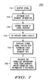
FIG. 3 , is stored in the buffer. In one embodiment, information for a single slot or not substantially more than a single slot of a frame is stored in the buffer. In other embodiments, the stored portion of the received signal includes page indication information for the subscriber device searching the pilot signals. - In the frame synchronization process flow diagram 700 of
FIG. 7 , the signal is received atblock 710 andStage 1 slot boundary information is determined atblock 720. Atblock 730, a portion of the received signal, for example, the continuous Common Pilot Channel (CPICH) signal is captured in memory for subsequent correlation with the scrambling codes. In some embodiments, less than one complete frame of information is stored in the buffer, and in other embodiments information for a single slot is stored in the buffer. The slot boundary information may be obtained from the stored signal portion, though in other embodiments determination of the slot boundaries duringStage 1 processing occurs prior to storage of the signal portion or partially concurrently with the signal storage operation. - In some embodiments, the stored portion of the signal includes paging information for the subscriber device, thereby eliminating the need to re-energize the receiver to obtain page indicator information.
- At
block 740, in some embodiments, after storing the received signal portion, the radio circuits are de-energized, thus reducing unnecessary power consumption associated with operation of the RF receiver during the correlation process. Determination of the frame boundary information and/or particular scrambling code information is performed by correlating the stored signal portion with the scrambling codes atblock 750, as discussed above, while the radio circuit is de-energized. - If after determination of the slot boundary information during
conventional Stage 1 signal processing, signal information for not substantially more than a single slot is captured or stored in the buffer, the radio circuit power ON time can be reduced from on the order of 10 ms (required for conventional Stage 2 and Stage 3 processing) to less than 1 ms, when using the synchronization process described above, substantially reducing charge drawn from the battery. - In
FIG. 7 , atblock 760, for each correlation, the correlated information is preferably integrated as long as is required to determine the frame boundary and/or scrambling code information In the exemplary UMTS synchronization application, the correlation of the common pilot channel, CPICH, with the scrambling codes permits the integration. - While the present disclosure and what are considered presently to be the best modes of the inventions have been described in a manner that establishes possession thereof by the inventors and that enables those of ordinary skill in the art to make and use the inventions, it will be understood and appreciated that there are many equivalents to the exemplary embodiments disclosed herein and that myriad modifications and variations may be made thereto without departing from the scope of the inventions, which are to be limited not by the exemplary embodiments but by the appended claims.
Claims (9)
- A method for frame synchronization and scrambling code identification in a wireless communications device, the method comprising:receiving a signal (710);determining slot boundary information of the signal (720), the method being characterized by:storing a portion of the signal (730)de-energising a radio receiver of the wireless communications device after storing the portion of the signal (740),determining frame boundary information of the stored signal portion by correlating the stored signal portion with several scrambling codes based upon the slot boundary information (750),identifying a particular scrambling code at the same time the frame boundary information is determined (760), wherein the signal is structured by frames and wherein storing the portion of the signal includes storing less than a complete frame.
- The method of Claim 1, correlating the stored signal portion with the scrambling codes based upon the slot boundary information includes aligning the scrambling codes relative to the stored signal portion based upon the slot boundary information before correlating the stored signal portion with the scrambling codes.
- The method of Claim 2, correlating the stored signal portion with the scrambling codes at each of several possible frame boundaries.
- The method of Claim 1, wherein storing a portion of the signal includes storing a portion of a continuous signal and wherein correlating includes correlating the stored portion with each of the scrambling codes.
- The method of Claim 1, wherein storing a portion of the signal includes storing a portion of a common pilot channel and wherein correlating includes correlating the stored portion with each of the scrambling codes.
- The method of Claim 1,
the slot boundary information includes time offset information;
correlating the stored signal portion with the scrambling codes based on the time offset information. - The method of Claim 1, for each correlation, integrating as long as is required to determine the frame boundary information.
- The method of Claim 1, storing page indication information for the wireless communications device when storing the portion of the signal.
- A wireless communications device (120) adapted to perform the steps of the method of any preceding claim.
Applications Claiming Priority (3)
| Application Number | Priority Date | Filing Date | Title |
|---|---|---|---|
| US10/376,191 US7061966B2 (en) | 2003-02-27 | 2003-02-27 | Frame synchronization and scrambling code indentification in wireless communications systems and methods therefor |
| US376191 | 2003-02-27 | ||
| PCT/US2004/006059 WO2004077735A2 (en) | 2003-02-27 | 2004-02-25 | Frame synchronization and scrambling code identification in wireless communications systems and methods therefor |
Publications (3)
| Publication Number | Publication Date |
|---|---|
| EP1599984A2 EP1599984A2 (en) | 2005-11-30 |
| EP1599984A4 EP1599984A4 (en) | 2010-02-17 |
| EP1599984B1 true EP1599984B1 (en) | 2012-09-05 |
Family
ID=32907915
Family Applications (1)
| Application Number | Title | Priority Date | Filing Date |
|---|---|---|---|
| EP04714684A Expired - Lifetime EP1599984B1 (en) | 2003-02-27 | 2004-02-25 | Frame synchronization and scrambling code identification in wireless communications systems and methods therefor |
Country Status (7)
| Country | Link |
|---|---|
| US (1) | US7061966B2 (en) |
| EP (1) | EP1599984B1 (en) |
| JP (1) | JP4504351B2 (en) |
| KR (1) | KR101061283B1 (en) |
| CN (1) | CN100593931C (en) |
| RU (1) | RU2352076C2 (en) |
| WO (1) | WO2004077735A2 (en) |
Families Citing this family (22)
| Publication number | Priority date | Publication date | Assignee | Title |
|---|---|---|---|---|
| KR100479864B1 (en) * | 2002-11-26 | 2005-03-31 | 학교법인 중앙대학교 | Method and apparatus embodying and synchronizing downlink signal in mobile communication system and method for searching cell using the same |
| US7463618B2 (en) * | 2003-08-04 | 2008-12-09 | Thomson Licensing | Frame synchronization in a universal mobile telephone system receiver |
| JP2006332957A (en) * | 2005-05-25 | 2006-12-07 | Matsushita Electric Ind Co Ltd | Communication terminal device |
| CN101273524A (en) * | 2005-08-16 | 2008-09-24 | 伟俄内克斯研究公司 | Frame synchronization |
| US7630445B1 (en) * | 2005-10-25 | 2009-12-08 | Magnolia Broadband Inc. | Establishing slot boundaries of slots of a diversity control feedback signal |
| US7715786B2 (en) * | 2006-02-08 | 2010-05-11 | The Directv Group, Inc. | Blind identification of advanced modulation and coding modes |
| US7639754B2 (en) * | 2006-03-29 | 2009-12-29 | Posdata Co., Ltd. | Method of detecting a frame boundary of a received signal in digital communication system and apparatus of enabling the method |
| FR2918828B1 (en) * | 2007-07-13 | 2009-09-18 | Wavecom Sa | METHOD OF DETECTING THE INTERFERENCE OF A RADIO COMMUNICATION NETWORK, COMPUTER PROGRAM PRODUCT, CORRESPONDING STORAGE MEDIUM AND CIRCUIT |
| US8009701B2 (en) | 2007-08-13 | 2011-08-30 | Qualcomm Incorporated | Secondary synchronization codebook for E-utran |
| US20090061892A1 (en) * | 2007-08-27 | 2009-03-05 | Via Telecom, Inc. | Location assisted connection to femtocell |
| US8103267B2 (en) * | 2007-09-26 | 2012-01-24 | Via Telecom, Inc. | Femtocell base station with mobile station capability |
| US8248923B2 (en) * | 2007-10-05 | 2012-08-21 | Via Telecom, Inc. | Automatic provisioning of admission policy for femtocell |
| US8223683B2 (en) * | 2007-10-05 | 2012-07-17 | VIA Telecom, Inc | Automatic provisioning of femtocell |
| US9363770B2 (en) * | 2007-10-05 | 2016-06-07 | Ipcomm | Automatic provisioning of handoff parameters for femtocell |
| US8213391B2 (en) * | 2007-10-05 | 2012-07-03 | Via Telecom, Inc. | Time synchronization of femtocell |
| US8937936B2 (en) * | 2007-10-05 | 2015-01-20 | Via Telecom Inc. | Acquiring time synchronization and location information with a femtocell |
| US8744493B2 (en) * | 2008-05-28 | 2014-06-03 | Via Telecom, Inc. | Localized silence area for mobile devices |
| CN101610122B (en) * | 2009-07-03 | 2013-03-20 | 中兴通讯股份有限公司 | Parallel frame synchronous scrambling device and descrambling device thereof |
| CN101692732B (en) * | 2009-10-22 | 2012-02-08 | 深圳市优网科技有限公司 | Method and device for distributing scrambling codes |
| CN102263609B (en) * | 2010-05-31 | 2014-03-05 | 国际商业机器公司 | Frame boundary detection method, equipment thereof, decoding method and system thereof |
| US8861452B2 (en) * | 2010-08-16 | 2014-10-14 | Qualcomm Incorporated | Method and apparatus for use of licensed spectrum for control channels in cognitive radio communications |
| WO2014125335A1 (en) * | 2013-02-15 | 2014-08-21 | Freescale Semiconductor, Inc. | Search method and apparatus for a communication system |
Citations (1)
| Publication number | Priority date | Publication date | Assignee | Title |
|---|---|---|---|---|
| WO2002095973A1 (en) * | 2001-05-18 | 2002-11-28 | Telefonaktiebolaget Lm Ericsson (Publ) | Systems and methods for selecting a cell in a communications network |
Family Cites Families (12)
| Publication number | Priority date | Publication date | Assignee | Title |
|---|---|---|---|---|
| CA2088993C (en) * | 1990-08-07 | 2002-03-12 | Karl-Axel Ahl | Modular radio communication system |
| US5640385A (en) * | 1994-01-04 | 1997-06-17 | Motorola, Inc. | Method and apparatus for simultaneous wideband and narrowband wireless communication |
| JP3372135B2 (en) * | 1995-05-24 | 2003-01-27 | ソニー株式会社 | Communication terminal device |
| US5793757A (en) * | 1996-02-13 | 1998-08-11 | Telefonaktiebolaget L M Ericsson (Publ) | Telecommunication network having time orthogonal wideband and narrowband sytems |
| US5987059A (en) * | 1996-07-12 | 1999-11-16 | General Electric Company | Method for Doppler-replica harmonic avoidance |
| US6144649A (en) * | 1997-02-27 | 2000-11-07 | Motorola, Inc. | Method and apparatus for acquiring a pilot signal in a CDMA receiver |
| US5991330A (en) * | 1997-06-27 | 1999-11-23 | Telefonaktiebolaget L M Ericsson (Pub1) | Mobile Station synchronization within a spread spectrum communication systems |
| US6185440B1 (en) * | 1997-12-10 | 2001-02-06 | Arraycomm, Inc. | Method for sequentially transmitting a downlink signal from a communication station that has an antenna array to achieve an omnidirectional radiation |
| KR100340932B1 (en) * | 1998-10-26 | 2002-06-20 | 조정남 | Cell searching method in asynchronous wideband code division multiple access system |
| US6480558B1 (en) * | 1999-03-17 | 2002-11-12 | Ericsson Inc. | Synchronization and cell search methods and apparatus for wireless communications |
| JP3836663B2 (en) * | 2000-09-04 | 2006-10-25 | 株式会社エヌ・ティ・ティ・ドコモ | Cell search method for mobile station in mobile communication system |
| US6744747B2 (en) * | 2001-08-22 | 2004-06-01 | Qualcomm, Incorporated | Method & apparatus for W-CDMA handoff searching |
-
2003
- 2003-02-27 US US10/376,191 patent/US7061966B2/en not_active Expired - Lifetime
-
2004
- 2004-02-25 EP EP04714684A patent/EP1599984B1/en not_active Expired - Lifetime
- 2004-02-25 CN CN200480004370A patent/CN100593931C/en not_active Expired - Lifetime
- 2004-02-25 RU RU2005130025/09A patent/RU2352076C2/en active
- 2004-02-25 KR KR1020057015911A patent/KR101061283B1/en not_active Expired - Lifetime
- 2004-02-25 JP JP2006503920A patent/JP4504351B2/en not_active Expired - Fee Related
- 2004-02-25 WO PCT/US2004/006059 patent/WO2004077735A2/en not_active Ceased
Patent Citations (1)
| Publication number | Priority date | Publication date | Assignee | Title |
|---|---|---|---|---|
| WO2002095973A1 (en) * | 2001-05-18 | 2002-11-28 | Telefonaktiebolaget Lm Ericsson (Publ) | Systems and methods for selecting a cell in a communications network |
Also Published As
| Publication number | Publication date |
|---|---|
| JP4504351B2 (en) | 2010-07-14 |
| JP2006519561A (en) | 2006-08-24 |
| KR101061283B1 (en) | 2011-08-31 |
| EP1599984A4 (en) | 2010-02-17 |
| WO2004077735A2 (en) | 2004-09-10 |
| CN1751490A (en) | 2006-03-22 |
| RU2005130025A (en) | 2006-01-27 |
| US7061966B2 (en) | 2006-06-13 |
| KR20050105256A (en) | 2005-11-03 |
| RU2352076C2 (en) | 2009-04-10 |
| EP1599984A2 (en) | 2005-11-30 |
| WO2004077735A3 (en) | 2005-04-14 |
| US20040170221A1 (en) | 2004-09-02 |
| CN100593931C (en) | 2010-03-10 |
Similar Documents
| Publication | Publication Date | Title |
|---|---|---|
| EP1599984B1 (en) | Frame synchronization and scrambling code identification in wireless communications systems and methods therefor | |
| EP2312768B1 (en) | Communications in an asynchronous wireless network | |
| US7013140B2 (en) | Mobile terminals and methods for performing fast initial frequency scans and cell searches | |
| CN1140152C (en) | Method and equipment for reducing power dissipation of communication apparatus | |
| US6480558B1 (en) | Synchronization and cell search methods and apparatus for wireless communications | |
| EP1025740B1 (en) | Method for searching cells in mobile communication system | |
| CN1695400B (en) | Dual Mode System and Dual Mode Wireless Terminal | |
| US7324479B2 (en) | Cell search method in UMTS | |
| EP2445116B1 (en) | Frequency Scan For CDMA Acquisition | |
| US7369534B2 (en) | Reducing search time using known scrambling code offsets | |
| JP2001320321A (en) | Method of operating a mobile station and mobile station | |
| US6263010B1 (en) | Spread spectrum communication apparatus | |
| US6718171B1 (en) | Robust and efficient reacquisition after call release | |
| US6807224B1 (en) | CDMA receiving apparatus and CDMA receiving method | |
| JP3892221B2 (en) | Mobile station, base station and communication method | |
| US7990901B2 (en) | Cell search scheduling in a wireless cellular communication network | |
| CN100380837C (en) | Receiving device and receiving method | |
| KR100698861B1 (en) | Dual mode system and dual mode wireless terminal | |
| HK1107488A1 (en) | Method and apparatus of acquiring time information in a mobile communication terminal |
Legal Events
| Date | Code | Title | Description |
|---|---|---|---|
| PUAI | Public reference made under article 153(3) epc to a published international application that has entered the european phase |
Free format text: ORIGINAL CODE: 0009012 |
|
| 17P | Request for examination filed |
Effective date: 20050825 |
|
| AK | Designated contracting states |
Kind code of ref document: A2 Designated state(s): AT BE BG CH CY CZ DE DK EE ES FI FR GB GR HU IE IT LI LU MC NL PT RO SE SI SK TR |
|
| AX | Request for extension of the european patent |
Extension state: AL LT LV MK |
|
| DAX | Request for extension of the european patent (deleted) | ||
| RBV | Designated contracting states (corrected) |
Designated state(s): DE FR GB IT |
|
| A4 | Supplementary search report drawn up and despatched |
Effective date: 20100119 |
|
| 17Q | First examination report despatched |
Effective date: 20100907 |
|
| RAP1 | Party data changed (applicant data changed or rights of an application transferred) |
Owner name: MOTOROLA MOBILITY, INC. |
|
| REG | Reference to a national code |
Ref country code: DE Ref legal event code: R079 Ref document number: 602004039202 Country of ref document: DE Free format text: PREVIOUS MAIN CLASS: H04L0027300000 Ipc: H04B0001707300 |
|
| GRAP | Despatch of communication of intention to grant a patent |
Free format text: ORIGINAL CODE: EPIDOSNIGR1 |
|
| RIC1 | Information provided on ipc code assigned before grant |
Ipc: H04B 1/7073 20110101AFI20120305BHEP |
|
| RTI1 | Title (correction) |
Free format text: FRAME SYNCHRONIZATION AND SCRAMBLING CODE IDENTIFICATION IN WIRELESS COMMUNICATIONS SYSTEMS AND METHODS THEREFOR |
|
| GRAS | Grant fee paid |
Free format text: ORIGINAL CODE: EPIDOSNIGR3 |
|
| GRAA | (expected) grant |
Free format text: ORIGINAL CODE: 0009210 |
|
| RAP1 | Party data changed (applicant data changed or rights of an application transferred) |
Owner name: MOTOROLA MOBILITY LLC |
|
| AK | Designated contracting states |
Kind code of ref document: B1 Designated state(s): DE FR GB IT |
|
| REG | Reference to a national code |
Ref country code: GB Ref legal event code: FG4D Ref country code: DE Ref legal event code: R081 Ref document number: 602004039202 Country of ref document: DE Owner name: GOOGLE TECHNOLOGY HOLDINGS LLC, MOUNTAIN VIEW, US Free format text: FORMER OWNER: MOTOROLA, INC., SCHAUMBURG, ILL., US |
|
| REG | Reference to a national code |
Ref country code: DE Ref legal event code: R096 Ref document number: 602004039202 Country of ref document: DE Effective date: 20121031 |
|
| PLBE | No opposition filed within time limit |
Free format text: ORIGINAL CODE: 0009261 |
|
| STAA | Information on the status of an ep patent application or granted ep patent |
Free format text: STATUS: NO OPPOSITION FILED WITHIN TIME LIMIT |
|
| 26N | No opposition filed |
Effective date: 20130606 |
|
| REG | Reference to a national code |
Ref country code: DE Ref legal event code: R097 Ref document number: 602004039202 Country of ref document: DE Effective date: 20130606 |
|
| REG | Reference to a national code |
Ref country code: FR Ref legal event code: PLFP Year of fee payment: 13 |
|
| REG | Reference to a national code |
Ref country code: FR Ref legal event code: PLFP Year of fee payment: 14 |
|
| REG | Reference to a national code |
Ref country code: GB Ref legal event code: 732E Free format text: REGISTERED BETWEEN 20170831 AND 20170906 |
|
| REG | Reference to a national code |
Ref country code: FR Ref legal event code: TP Owner name: GOOGLE TECHNOLOGY HOLDINGS LLC, US Effective date: 20171214 |
|
| REG | Reference to a national code |
Ref country code: FR Ref legal event code: PLFP Year of fee payment: 15 |
|
| REG | Reference to a national code |
Ref country code: DE Ref legal event code: R081 Ref document number: 602004039202 Country of ref document: DE Owner name: GOOGLE TECHNOLOGY HOLDINGS LLC, MOUNTAIN VIEW, US Free format text: FORMER OWNER: MOTOROLA MOBILITY LLC, LIBERTYVILLE, ILL., US |
|
| PGFP | Annual fee paid to national office [announced via postgrant information from national office to epo] |
Ref country code: FR Payment date: 20230223 Year of fee payment: 20 |
|
| PGFP | Annual fee paid to national office [announced via postgrant information from national office to epo] |
Ref country code: IT Payment date: 20230221 Year of fee payment: 20 Ref country code: GB Payment date: 20230227 Year of fee payment: 20 Ref country code: DE Payment date: 20230223 Year of fee payment: 20 |
|
| P01 | Opt-out of the competence of the unified patent court (upc) registered |
Effective date: 20230512 |
|
| REG | Reference to a national code |
Ref country code: DE Ref legal event code: R071 Ref document number: 602004039202 Country of ref document: DE |
|
| REG | Reference to a national code |
Ref country code: GB Ref legal event code: PE20 Expiry date: 20240224 |
|
| PG25 | Lapsed in a contracting state [announced via postgrant information from national office to epo] |
Ref country code: GB Free format text: LAPSE BECAUSE OF EXPIRATION OF PROTECTION Effective date: 20240224 |