EP1599273B1 - Dispositif de filtre huile - Google Patents
Dispositif de filtre huile Download PDFInfo
- Publication number
- EP1599273B1 EP1599273B1 EP04717077A EP04717077A EP1599273B1 EP 1599273 B1 EP1599273 B1 EP 1599273B1 EP 04717077 A EP04717077 A EP 04717077A EP 04717077 A EP04717077 A EP 04717077A EP 1599273 B1 EP1599273 B1 EP 1599273B1
- Authority
- EP
- European Patent Office
- Prior art keywords
- filter element
- housing
- cover
- covering
- oil
- Prior art date
- Legal status (The legal status is an assumption and is not a legal conclusion. Google has not performed a legal analysis and makes no representation as to the accuracy of the status listed.)
- Expired - Lifetime
Links
- 238000007789 sealing Methods 0.000 claims description 16
- 239000000463 material Substances 0.000 claims description 3
- 230000000295 complement effect Effects 0.000 claims 1
- 239000003921 oil Substances 0.000 abstract description 32
- 239000010779 crude oil Substances 0.000 abstract description 11
- 230000000694 effects Effects 0.000 description 4
- 238000002485 combustion reaction Methods 0.000 description 2
- 230000003750 conditioning effect Effects 0.000 description 2
- 238000010276 construction Methods 0.000 description 2
- 238000009434 installation Methods 0.000 description 2
- 238000004064 recycling Methods 0.000 description 2
- 230000005540 biological transmission Effects 0.000 description 1
- 230000006835 compression Effects 0.000 description 1
- 238000007906 compression Methods 0.000 description 1
- 230000009977 dual effect Effects 0.000 description 1
- 238000001914 filtration Methods 0.000 description 1
- 238000001746 injection moulding Methods 0.000 description 1
- 238000005461 lubrication Methods 0.000 description 1
- 239000002245 particle Substances 0.000 description 1
- 210000002105 tongue Anatomy 0.000 description 1
Images
Classifications
-
- B—PERFORMING OPERATIONS; TRANSPORTING
- B01—PHYSICAL OR CHEMICAL PROCESSES OR APPARATUS IN GENERAL
- B01D—SEPARATION
- B01D35/00—Filtering devices having features not specifically covered by groups B01D24/00 - B01D33/00, or for applications not specifically covered by groups B01D24/00 - B01D33/00; Auxiliary devices for filtration; Filter housing constructions
- B01D35/14—Safety devices specially adapted for filtration; Devices for indicating clogging
- B01D35/147—Bypass or safety valves
-
- B—PERFORMING OPERATIONS; TRANSPORTING
- B01—PHYSICAL OR CHEMICAL PROCESSES OR APPARATUS IN GENERAL
- B01D—SEPARATION
- B01D35/00—Filtering devices having features not specifically covered by groups B01D24/00 - B01D33/00, or for applications not specifically covered by groups B01D24/00 - B01D33/00; Auxiliary devices for filtration; Filter housing constructions
- B01D35/14—Safety devices specially adapted for filtration; Devices for indicating clogging
- B01D35/153—Anti-leakage or anti-return valves
-
- B—PERFORMING OPERATIONS; TRANSPORTING
- B01—PHYSICAL OR CHEMICAL PROCESSES OR APPARATUS IN GENERAL
- B01D—SEPARATION
- B01D35/00—Filtering devices having features not specifically covered by groups B01D24/00 - B01D33/00, or for applications not specifically covered by groups B01D24/00 - B01D33/00; Auxiliary devices for filtration; Filter housing constructions
- B01D35/16—Cleaning-out devices, e.g. for removing the cake from the filter casing or for evacuating the last remnants of liquid
-
- B—PERFORMING OPERATIONS; TRANSPORTING
- B01—PHYSICAL OR CHEMICAL PROCESSES OR APPARATUS IN GENERAL
- B01D—SEPARATION
- B01D35/00—Filtering devices having features not specifically covered by groups B01D24/00 - B01D33/00, or for applications not specifically covered by groups B01D24/00 - B01D33/00; Auxiliary devices for filtration; Filter housing constructions
- B01D35/30—Filter housing constructions
-
- B—PERFORMING OPERATIONS; TRANSPORTING
- B01—PHYSICAL OR CHEMICAL PROCESSES OR APPARATUS IN GENERAL
- B01D—SEPARATION
- B01D2201/00—Details relating to filtering apparatus
- B01D2201/29—Filter cartridge constructions
- B01D2201/291—End caps
-
- B—PERFORMING OPERATIONS; TRANSPORTING
- B01—PHYSICAL OR CHEMICAL PROCESSES OR APPARATUS IN GENERAL
- B01D—SEPARATION
- B01D2201/00—Details relating to filtering apparatus
- B01D2201/30—Filter housing constructions
- B01D2201/301—Details of removable closures, lids, caps, filter heads
- B01D2201/304—Seals or gaskets
-
- B—PERFORMING OPERATIONS; TRANSPORTING
- B01—PHYSICAL OR CHEMICAL PROCESSES OR APPARATUS IN GENERAL
- B01D—SEPARATION
- B01D2201/00—Details relating to filtering apparatus
- B01D2201/30—Filter housing constructions
- B01D2201/301—Details of removable closures, lids, caps, filter heads
- B01D2201/305—Snap, latch or clip connecting means
Definitions
- the invention relates to an oil filter assembly
- a housing having a receiving space for a filter element can be inserted into the housing, and with a housing cover closing the receiving space, wherein the filter element can be flowed through by unfiltered crude oil in the radial direction and at its lower end face in installation position a drain opening for filtered oil, wherein the filter element is sealed at the lower end face against the receiving space and the housing.
- a generic oil filter assembly is known from DE 34 09 219 C2.
- a lid is provided, which also serves to close the receiving space in the housing.
- the lid and the filter element are connected to each other, so that an exchange unit is formed, which can then be disposed of and replaced by a new unit.
- the described construction creates the problem that the lid has to perform two functions. First, the lid must reliably close the receiving space of the housing, on the other hand, the lid must form a reliable seal between the crude oil and the clean oil side of the filter element. This dual function is problematic in that not inconsiderable length expansions can lead to the fact that only one of the sealing functions can be reliably met in the temperature and oil pressure fluctuations and the plastic materials used during operation of an oil filter assembly.
- the oil filter assembly according to the invention has the significant advantage that with simple, tolerance-insensitive components, a reliable sealing of the upper end side of the filter element can be done. Due to the fact that the housing cover only has to fulfill a sealing function with respect to the housing in the embodiment according to the invention and the filter element-side sealing is effected by the separate cover, the filter element can be sealed particularly reliably.
- the filter element-side cover seals the entire upper end face of the filter element, without openings for bypass valves or additional elements are provided, which can form potential leakage points.
- a handle-like portion is provided on the side facing away from the filter element of the cover.
- the housing cover is first unscrewed from the housing.
- the cover can be detected and removed at the handle-like portion.
- the handle-like portion may be formed, for example, as a survey, trough or eyelet.
- At least one undercut element is provided on the filter element facing side of the housing cover, which entrains the handle-like portion of the cover in the axial direction when unscrewing the housing cover from the housing and thus removes the cover from the receiving space.
- the undercut elements may be formed, for example, as tongues or tabs, which at least partially grasp the handle-like portion and thus the cover already removed when unscrewing the housing cover from the housing. Thus, a work can be saved when replacing the filter element.
- the filter element is fixed in the axial direction by conditioning the cover on the housing cover and by conditioning on the housing.
- the filter element can be fixed in the region of its upper end side by the elements housing cover and cover and in the region of the lower end side by the housing.
- a relatively small clamping force is sufficient to prevent an axial movement of the filter element within the receiving space.
- intermediate elements for transmitting axial and / or radial contact forces are provided on the housing cover and / or on the cover.
- These intermediate elements may for example be formed directly on the housing cover and / or the cover, so that they are integrally produced, for example, by an injection molding process.
- the housing cover or the cover has centering and / or positioning sections in the form of cylinder wall sections extending at least partially over a circumference, whose end faces engage in an annular groove formed on the cover or on the housing cover.
- the cylinder wall sections can also be provided on the cover and the annular groove on or in the housing cover.
- the proposed rotationally symmetrical design is advantageous because the housing cover when screwed onto the housing through the cylinder wall sections or the annular groove can transmit compressive forces in the axial direction, without causing the filter element with its cover also performs a rotational movement.
- optionally provided on the lower end face of the filter element O-ring seals are spared during assembly of the filter element.
- the filter element can be removed directly together with the cover from the receiving space of the housing, either by manually detecting the handle-like portion with unscrewed housing cover or, in the arrangement of Undercut elements in the housing cover, directly when unscrewing the housing cover from the housing.
- a development of the invention provides that the cover on the side facing the filter element has an annular web, which surrounds the filter element radially on the outside. In this way, the cover and the filter element in the region of the upper end side can be positioned in the radial direction to each other. If the above-mentioned cylinder wall sections or annular grooves are provided on the housing or on the cover, the filter element is arranged concentrically with respect to the housing cover and thus concentrically with the receiving space via the annular web and via the annular groove or the cylinder wall sections. Thus, a uniform filtering effect is generated regardless of the entry point of the crude oil in the circumferential direction.
- an inner socket is provided, which is formed from a cylinder wall portion and projects into the receiving space.
- the sealing of the lower end face of the filter element against the receiving space takes place with the aid of an annular disc portion, which is followed by a the inner sleeve of the housing overlapping collar for sealing against the inner socket of the housing.
- a ring seal is provided between the receiving space facing end face of the cylinder wall portion of the inner nozzle and the collar. Due to the arrangement of the ring seal between the end face of the cylinder wall portion of the inner nozzle and the collar a reliable sealing of the filter element is also possible on its lower end face.
- the ring seal in turn is supported on the end face of the cylinder wall portion of the inner nozzle of the housing.
- the cover and / or the annular disc portion and the adjoining collar and / or provided in the interior of the filter element Kollabierschutz of the same material, in particular of the same type of plastic produced can be facilitated.
- a pressure relief valve is provided adjacent to the receiving space in the housing, which is aligned axially parallel to the filter element.
- This pressure relief valve is used to ensure that when the filter element is clogged, the oil required for the lubrication of an internal combustion engine is still available, albeit bypassing the filter element.
- the pressure relief valve can be welded into a receiving opening in the housing. As a result, a reliable connection between the pressure relief valve and the housing is made possible and prevents inadvertent release of the pressure relief valve from its installation as far as possible.
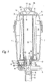
- FIG. 1 shows an oil filter arrangement with a substantially pot-shaped housing 2, which forms a substantially cylindrical receiving space 4.
- a ring filter element 6 is inserted in the receiving space 4.
- the receiving space 4 of the housing 2 can be closed with a housing cover 8 which can be screwed onto the housing 2.
- Surrounding the filter element 6 is provided an annular space 10 for entering into the filter element 6 crude oil.
- the crude oil flows through the filter element 6 in the radial direction and enters a centrally arranged space 12 for pure oil.
- the filtered pure oil passes according to the course shown in dashed lines to a drain 14th
- a substantially disc-shaped cover 16 is provided at the upper end side of the filter element 6, .
- the cover 16 extends over the entire upper end face of the filter element 6 and is firmly connected thereto.
- an annular web 20 is provided, which surrounds the filter element 6 radially outward. As a result, the filter element 6 and the cover 16 are aligned centrally with each other.
- a circumferentially annular groove 24 is provided, into which engages the end face of an integrally formed on the housing cover 8 annular collar-like cylinder wall 26. Axial forces can be transmitted from the housing cover 8 via the cylinder wall 26 and the groove 24 to the cover 16 or the filter element 6 through the cylinder wall 26 or the groove 24.
- an eyelet handle-like portion 28 is also provided, which serves as an assembly aid in the replacement of the filter element 6.
- the eyelet 28 can be taken manually or by means of a gripping tool to remove the cover 16 and the associated with the cover 16 filter element 6 from the receiving space 4 of the housing 2.
- the eyelet 28 is arranged in an inner space 30, which is formed by an extension 32, which is part of the housing cover 8.
- the extension 32 has on its outer side 35 a hexagonal profile on which a jaw or ring spanner can be placed in order to unscrew the housing cover 8 from the housing 2 can.
- annular disc portion 34 is provided, on the radially outer ring land 36 is integrally formed.
- the annular disc portion 34 and the annular web 36 seal the filter element 6 at its lower end against the receiving space 4.
- a collar 38 which in turn provided on a provided on the lower end side of the filter element 6 locking pin 40 is formed.
- the collar 38 surrounds an integrally formed on the bottom 42 of the housing 2 cylindrical inner socket 44.
- the inner socket 44 is connected via an O-ring 46th sealed against the inner wall of the inner nozzle 44 and thus against the housing 2.
- the closure pin 40 has a central bore 48 through which filtered pure oil from the space 12 can flow to the drain 14.
- one or more outlet openings 50 are provided, which communicate with the bore 48 in the closure pin 40.
- a drainage closure 52 for a drainage 54 is provided.
- an O-ring 56 is provided for sealing the drainage closure 52 with respect to the drainage 54.
- the cover 16, the closure pin 40 with collar 38 and washer portion 34 and annular ridge 36 and provided in the interior of the filter element 6 Kollabierschutz 58 are made of the same type of plastic to facilitate a sorted disposal or recycling of the components.
- a pressure relief valve 60 is integrated, which is supported by a circumferential collar 62 on an annular receiving portion 64 in the housing 2 and is welded there.
- the pressure relief valve 60 has a valve body 66 which bears against a valve seat 68.
- the oil filter assembly shown operates in normal operation so that unfiltered crude oil passes through an inlet, not shown, in the crude oil chamber 10, from there the filter element 6 flows from radially outside to inside and enters the clean oil chamber 12. From there it can via the formed in the plug 40 bore 48 and the outlet openings 50 to the drain 14th reach.
- dirt particles settled on this so that the passage of the crude oil from the space 10 into the space 12 is difficult. For particularly heavy pollution, it is possibly no longer possible for the crude oil to pass from the space 10 into the space 12.
- the filter element 6 can be bypassed by the pressure relief valve 60 opens from a certain oil pressure in the space 10.
- the valve body 66 is raised against the action of a compression spring, not shown, from its valve seat 68, so that in the space 10 befindliches oil can be fed via the pressure relief valve 60 to the drain 14.
- the housing cover 8 When replacing the filter element 6, the housing cover 8 is unscrewed from the housing 2. In the next step, the eyelet 28 is grasped and thus the cover 16, the filter element 6 and the inner socket 40 are removed from the receiving space 2. When the closure pin 40 is withdrawn, the drainage closure 52 is also lifted out of the drainage 54, so that oil located in the receiving space 4 of the housing 2 can drain away through the drainage 54.
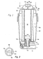
- FIG. 2 Another embodiment of an oil filter assembly is shown.
- This oil filter assembly also has a housing 102 with a receiving space 104 and a filter element 106, wherein the receiving space 104 can be closed by a housing cover 108.
- the mode of operation of the embodiment of the oil filter arrangement shown in FIG. 2 essentially corresponds to the mode of operation of the embodiment shown in FIG. Therefore, in the following, only the differences from the embodiment according to FIG. 1 will be discussed in detail.
- a cover 116 is provided, on which (similar to Figure 1) an annular web 120 is provided.
- a handle 128 is formed, which projects into an inner space 130 which is formed in a central, upper portion of the housing cover 108.
- the interior 130 to the filter element 106 towards limiting, tongue-shaped undercut elements 170 are provided.
- the undercut element 170 are adapted to grip the handle 128 from below, to unscrew the housing cover 108 from the housing 102, the cover 116 and connected to the cover 116 filter element 106 and provided on the lower side of the filter element 106 closure pin 140 from the To remove receiving space 104 of the housing 102. After removing the filter element 106 from the receiving space 104, the handle 128 can be led out laterally out of the region of the undercut elements 170 (see also FIG. 3). Thus, the filter element 106 is released together with its cover 116 from the housing cover.
- a collar 138 is integrally formed, which in turn is followed by an annular disk section 134, which seals the filter element 106 at its lower end side against the receiving space 104.
- the collar 138 surrounds a formed on the housing bottom 142 inner sleeve 144.
- the inner sleeve 144 is cylindrical and engages in the closure pin 140 formed on the collar 138.
- an additional O-ring seal 172 is provided between the end faces of the inner sleeve 144 and the collar 138.
- This O-ring seal 172 is acted upon by the cover 138 in the axial direction with compressive force via the collar 138, via the annular disk sections 134 and the filter element 106 and the cover 116. This will achieved a reliable seal between the inner sleeve 144 of the housing 2 and the collar 138 of the locking pin 140.
Landscapes
- Chemical & Material Sciences (AREA)
- Chemical Kinetics & Catalysis (AREA)
- Lubrication Details And Ventilation Of Internal Combustion Engines (AREA)
- Fats And Perfumes (AREA)
Claims (12)
- Système de filtre à huile, comportant un boîtier (102), qui contient un logement (104) pour un élément filtrant (106) à insérer dans le boîtier (102), et comportant un couvercle de boîtier (108), obturant le logement (104), l'élément filtrant (106) étant propre à être traversé dans la direction radiale par l'huile brute non filtrée et comportant sur sa face frontale inférieure, dans la position de montage, un orifice de sortie (148) pour l'huile filtrée, la face frontale inférieure de l'élément filtrant étant rendue étanche vis-à-vis du logement (104) et du boîtier (102), caractérisé en ce que toute la face frontale supérieure de l'élément filtrant (106) est rendue étanche vis-à-vis du logement (104) par un cache (116), réalisé du côté de l'élément filtrant séparément du couvercle (108), et en ce qu'une partie (128) en forme de poignée est prévue sur le côté (122) du cache (116), opposé à l'élément filtrant (106), et des éléments détalonnés (170) en forme de pattes sont prévus sur le côté du couvercle (108), orienté vers l'élément filtrant (106), de telle sorte que, au moment du dévissage du couvercle (108) du boîtier (102), les éléments détalonnés (170) saisissent par le bas la partie en forme de poignée (128) et l'entraînent dans la direction axiale, la partie en forme de poignée (128) pouvant être retirée latéralement hors de la zone des éléments détalonnés (170) une fois que l'élément filtrant (106) a été extrait du logement (104).
- Système de filtre à huile selon la revendication 1, caractérisé en ce que l'élément filtrant (106) est fixé dans la direction axiale par l'appui du cache (116) contre le couvercle (108) et par l'appui contre le boîtier (102).
- Système de filtre à huile selon la revendication 2, caractérisé en ce que des éléments intermédiaires, destinés à transmettre les forces d'appui axiales et/ou radiales, sont prévus sur le couvercle (108) et/ou sur le cache (116).
- Système de filtre à huile selon la revendication 3, caractérisé en ce que respectivement le couvercle (108) et le cache (116) comportent des parties de positionnement et/ou de centrage, qui coopèrent avec des parties de positionnement et/ou de centrage complémentaires prévues respectivement sur le cache (116) et sur le couvercle (108).
- Système de filtre à huile selon la revendication 3 ou 4, caractérisé en ce que respectivement le couvercle (108) et le cache (116) comportent des parties de paroi cylindriques (126), qui s'étendent au moins partiellement sur un pourtour circulaire et dont les faces frontales s'engagent dans une rainure annulaire (116) réalisée respectivement sur le cache (116) et sur le couvercle (108).
- Système de filtre à huile selon l'une quelconque des revendications précédentes, caractérisé en ce que la partie en forme de poignée est réalisée sous forme de surélévation (128).
- Système de filtre à huile selon l'une quelconque des revendications précédentes, caractérisé en ce que le cache (116) est assemblé de manière inamovible à l'élément filtrant (106).
- Système de filtre à huile selon l'une quelconque des revendications précédentes, caractérisé en ce que le cache (116), sur le côté orienté vers l'élément filtrant (106), comporte une nervure annulaire (120) qui enserre radialement de l'extérieur l'élément filtrant (106).
- Système de filtre à huile selon l'une quelconque des revendications précédentes, caractérisé en ce que sur le fond (142) du boîtier (102) est prévue une tubulure intérieure (144) qui est formée par un tronçon cylindrique et s'engage dans le logement (104), et l'étanchéité de la face frontale inférieure de l'élément filtrant (106) vis-à-vis du logement (104) étant assurée au moyen d'une partie en disque annulaire (134), qui est prolongée par un collet (138) recouvrant la tubulure intérieure (144) du boîtier (102) pour assurer l'étanchéité vis-à-vis de la tubulure intérieure du boîtier, un joint d'étanchéité annulaire (172) étant prévu entre la face frontale, orientée vers le logement (104), de la partie dé paroi cylindrique de la tubulure intérieure (144) et le collet (138).
- Système de filtre à huile selon la revendication 9, caractérisé en ce que le cache (116) et/ou la partie en disque annulaire (134) et le collet (138) adjacent à celle-ci et/ou une protection de cartouche prévue à l'intérieur de l'élément filtrant (106) sont réalisés dans le même matériau.
- Système de filtre à huile selon l'une quelconque des revendications précédentes, caractérisé en ce que, à proximité du logement (104) dans le boîtier (102), il est prévu une soupape de sûreté qui est orientée parallèlement à l'axe de l'élément filtrant (106).
- Système de filtre à huile selon la revendication 11, caractérisé en ce que la soupape de sûreté peut être soudée à l'intérieur d'un orifice de réception dans le boîtier (102).
Applications Claiming Priority (3)
| Application Number | Priority Date | Filing Date | Title |
|---|---|---|---|
| DE10309442 | 2003-03-05 | ||
| DE10309442A DE10309442A1 (de) | 2003-03-05 | 2003-03-05 | Ölfilteranordnung |
| PCT/EP2004/002167 WO2004078317A1 (fr) | 2003-03-05 | 2004-03-04 | Dispositif de filtre à huile |
Publications (2)
| Publication Number | Publication Date |
|---|---|
| EP1599273A1 EP1599273A1 (fr) | 2005-11-30 |
| EP1599273B1 true EP1599273B1 (fr) | 2006-12-06 |
Family
ID=32891864
Family Applications (1)
| Application Number | Title | Priority Date | Filing Date |
|---|---|---|---|
| EP04717077A Expired - Lifetime EP1599273B1 (fr) | 2003-03-05 | 2004-03-04 | Dispositif de filtre huile |
Country Status (4)
| Country | Link |
|---|---|
| EP (1) | EP1599273B1 (fr) |
| AT (1) | ATE347430T1 (fr) |
| DE (2) | DE10309442A1 (fr) |
| WO (1) | WO2004078317A1 (fr) |
Families Citing this family (5)
| Publication number | Priority date | Publication date | Assignee | Title |
|---|---|---|---|---|
| DE102006034485A1 (de) * | 2006-07-21 | 2008-01-24 | Joma-Polytec Kunststofftechnik Gmbh | Ölfilteranordnung |
| DE102010033508A1 (de) * | 2010-08-05 | 2012-02-09 | Mahle International Gmbh | Fluidfilter |
| DE102014001722B4 (de) * | 2014-02-11 | 2017-02-02 | Mann+Hummel Gmbh | Filtergehäuse und Fluidfilter |
| DE102017004275A1 (de) * | 2017-05-04 | 2018-11-08 | Mann+Hummel Gmbh | Filterelement zur Flüssigkeitsfiltration |
| DE102023115237A1 (de) | 2023-06-12 | 2024-12-12 | Daimler Truck AG | Austauschbare Komponente |
Family Cites Families (11)
| Publication number | Priority date | Publication date | Assignee | Title |
|---|---|---|---|---|
| US4423751A (en) * | 1980-12-09 | 1984-01-03 | Cummins Engine Company, Inc. | Bypass valve and alarm assembly |
| DE3409219A1 (de) * | 1984-03-14 | 1985-09-19 | Ing. Walter Hengst GmbH & Co KG, 4400 Münster | Oelfilter zum reinigen von schmieroel eines verbrennungsmotors |
| DE3538589A1 (de) * | 1985-10-30 | 1987-05-07 | Hengst Walter Gmbh & Co Kg | Oelfilter zum reinigen von schmieroel |
| DE3903675A1 (de) * | 1989-02-08 | 1990-08-09 | Knecht Filterwerke Gmbh | Oelfilter zum reinigen von schmieroel |
| DE59208594D1 (de) * | 1991-03-28 | 1997-07-10 | Knecht Filterwerke Gmbh | Flüssigkeitsfilter |
| GB9412862D0 (en) * | 1994-06-27 | 1994-08-17 | Pall Corp | Filter assemblies |
| DE19507485A1 (de) * | 1995-03-03 | 1996-09-05 | Hoechst Ag | Formkörper mit Filtervorrichtung |
| JP3863565B2 (ja) * | 1995-06-17 | 2006-12-27 | マーレ フィルタージステーメ ゲゼルシャフト ミット ベシュレンクテル ハフツング | 特に燃焼機関のための潤滑油フィルタ |
| US5667699A (en) * | 1996-06-17 | 1997-09-16 | Schlise; Larry | Method and device for removing waste oil from oil filters |
| DE19949564A1 (de) * | 1999-10-14 | 2001-04-19 | Mann & Hummel Filter | Flüssigkeitsfilter mit Filterumgehungsventil |
| DE19951085A1 (de) * | 1999-10-23 | 2001-04-26 | Mahle Filtersysteme Gmbh | Flüssigkeitsfilter, insbesondere Ölfilter |
-
2003
- 2003-03-05 DE DE10309442A patent/DE10309442A1/de not_active Withdrawn
-
2004
- 2004-03-04 AT AT04717077T patent/ATE347430T1/de active
- 2004-03-04 DE DE502004002233T patent/DE502004002233D1/de not_active Expired - Lifetime
- 2004-03-04 WO PCT/EP2004/002167 patent/WO2004078317A1/fr not_active Ceased
- 2004-03-04 EP EP04717077A patent/EP1599273B1/fr not_active Expired - Lifetime
Also Published As
| Publication number | Publication date |
|---|---|
| ATE347430T1 (de) | 2006-12-15 |
| EP1599273A1 (fr) | 2005-11-30 |
| WO2004078317A1 (fr) | 2004-09-16 |
| DE502004002233D1 (de) | 2007-01-18 |
| DE10309442A1 (de) | 2004-09-23 |
Similar Documents
| Publication | Publication Date | Title |
|---|---|---|
| EP0692292B2 (fr) | Filtre à liquides | |
| DE69609975T2 (de) | Wiederverwendbarer flüssigkeitsfilter und adapter. | |
| EP0748646B1 (fr) | Filtre de liquide | |
| EP3329979B1 (fr) | Boitier pour un filtre et élément filtrant | |
| EP1137470B1 (fr) | Filtre a fluide comportant un dome d'evacuation | |
| EP2102484B1 (fr) | Filtre à carburant d'un moteur à combustion de véhicule | |
| EP1974786B1 (fr) | Filtre liquide | |
| DE19539918C1 (de) | Flüssigkeitsfilter, insbesondere für Öl oder Kraftstoff einer Brennkraftmaschine, und dazu passender maschinenseitiger Filteranschlußflansch | |
| EP2051792B1 (fr) | Élément filtre, en particulier pour le filtrage de liquides ou de gaz | |
| EP3096859B1 (fr) | Élément de filtration | |
| DE20004431U1 (de) | Flüssigkeitsfilter mit Umgehungsventil | |
| DE102016000157B4 (de) | Filtersystem, Verschlusselement und Filterelement | |
| EP2283910B1 (fr) | Filtre à liquide, notamment filtre à huile | |
| EP1935468A1 (fr) | Filtre à carburant | |
| EP1131542A1 (fr) | Filtre a liquide, notamment pour huile ou carburant de moteur a combustion interne | |
| WO2014082762A1 (fr) | Filtre, élément filtrant, boîtier de filtre et dispositif de purge d'un filtre | |
| EP1648583B1 (fr) | Ensemble filtre a huile et element filtrant | |
| EP2910289A1 (fr) | Dispositif de filtre | |
| EP3999204B1 (fr) | Filtre à fluide pour un véhicule à moteur et cartouche filtrante pour un filtre à fluide de ce type | |
| DE29915844U1 (de) | Filter mit Ventil-Kombinationsbauteil | |
| EP1888198A2 (fr) | Dispositif filtrant, notamment pour la filtration de liquides dans des moteurs a combustion interne | |
| EP1599273B1 (fr) | Dispositif de filtre huile | |
| EP3727643B1 (fr) | Élément filtrant d'un filtre à liquide et filtre | |
| DE29922324U1 (de) | Flüssigkeitsfilter | |
| DE102020123586B4 (de) | Filterelement, Filtereinrichtung, Anordnung und Montageverfahren |
Legal Events
| Date | Code | Title | Description |
|---|---|---|---|
| PUAI | Public reference made under article 153(3) epc to a published international application that has entered the european phase |
Free format text: ORIGINAL CODE: 0009012 |
|
| 17P | Request for examination filed |
Effective date: 20050723 |
|
| AK | Designated contracting states |
Kind code of ref document: A1 Designated state(s): AT BE BG CH CY CZ DE DK EE ES FI FR GB GR HU IE IT LI LU MC NL PL PT RO SE SI SK TR |
|
| AX | Request for extension of the european patent |
Extension state: AL LT LV MK |
|
| GRAP | Despatch of communication of intention to grant a patent |
Free format text: ORIGINAL CODE: EPIDOSNIGR1 |
|
| DAX | Request for extension of the european patent (deleted) | ||
| RBV | Designated contracting states (corrected) |
Designated state(s): AT DE FR GB |
|
| GRAS | Grant fee paid |
Free format text: ORIGINAL CODE: EPIDOSNIGR3 |
|
| GRAA | (expected) grant |
Free format text: ORIGINAL CODE: 0009210 |
|
| AK | Designated contracting states |
Kind code of ref document: B1 Designated state(s): AT DE FR GB |
|
| REG | Reference to a national code |
Ref country code: GB Ref legal event code: FG4D Free format text: NOT ENGLISH |
|
| REF | Corresponds to: |
Ref document number: 502004002233 Country of ref document: DE Date of ref document: 20070118 Kind code of ref document: P |
|
| GBT | Gb: translation of ep patent filed (gb section 77(6)(a)/1977) |
Effective date: 20070117 |
|
| ET | Fr: translation filed | ||
| PLBE | No opposition filed within time limit |
Free format text: ORIGINAL CODE: 0009261 |
|
| STAA | Information on the status of an ep patent application or granted ep patent |
Free format text: STATUS: NO OPPOSITION FILED WITHIN TIME LIMIT |
|
| 26N | No opposition filed |
Effective date: 20070907 |
|
| REG | Reference to a national code |
Ref country code: DE Ref legal event code: R082 Ref document number: 502004002233 Country of ref document: DE Representative=s name: DREISS PATENTANWAELTE PARTNERSCHAFT, DE |
|
| REG | Reference to a national code |
Ref country code: DE Ref legal event code: R081 Ref document number: 502004002233 Country of ref document: DE Owner name: MANN + HUMMEL GMBH, DE Free format text: FORMER OWNER: JOMA-POLYTEC GMBH, 72411 BODELSHAUSEN, DE Effective date: 20130719 Ref country code: DE Ref legal event code: R082 Ref document number: 502004002233 Country of ref document: DE Representative=s name: DREISS PATENTANWAELTE PARTNERSCHAFT, DE Effective date: 20130719 Ref country code: DE Ref legal event code: R082 Ref document number: 502004002233 Country of ref document: DE Representative=s name: DREISS PATENTANWAELTE PARTG MBB, DE Effective date: 20130719 |
|
| REG | Reference to a national code |
Ref country code: AT Ref legal event code: PC Ref document number: 347430 Country of ref document: AT Kind code of ref document: T Owner name: MANN + HUMMEL GMBH, DE Effective date: 20130808 |
|
| REG | Reference to a national code |
Ref country code: GB Ref legal event code: 732E Free format text: REGISTERED BETWEEN 20130905 AND 20130911 |
|
| REG | Reference to a national code |
Ref country code: FR Ref legal event code: TP Owner name: MANN + HUMMEL GMBH, DE Effective date: 20131108 |
|
| REG | Reference to a national code |
Ref country code: FR Ref legal event code: PLFP Year of fee payment: 13 |
|
| REG | Reference to a national code |
Ref country code: FR Ref legal event code: PLFP Year of fee payment: 14 |
|
| PGFP | Annual fee paid to national office [announced via postgrant information from national office to epo] |
Ref country code: DE Payment date: 20170322 Year of fee payment: 14 Ref country code: FR Payment date: 20170322 Year of fee payment: 14 |
|
| PGFP | Annual fee paid to national office [announced via postgrant information from national office to epo] |
Ref country code: AT Payment date: 20170322 Year of fee payment: 14 Ref country code: GB Payment date: 20170322 Year of fee payment: 14 |
|
| REG | Reference to a national code |
Ref country code: DE Ref legal event code: R119 Ref document number: 502004002233 Country of ref document: DE |
|
| REG | Reference to a national code |
Ref country code: AT Ref legal event code: MM01 Ref document number: 347430 Country of ref document: AT Kind code of ref document: T Effective date: 20180304 |
|
| GBPC | Gb: european patent ceased through non-payment of renewal fee |
Effective date: 20180304 |
|
| PG25 | Lapsed in a contracting state [announced via postgrant information from national office to epo] |
Ref country code: AT Free format text: LAPSE BECAUSE OF NON-PAYMENT OF DUE FEES Effective date: 20180304 Ref country code: DE Free format text: LAPSE BECAUSE OF NON-PAYMENT OF DUE FEES Effective date: 20181002 |
|
| PG25 | Lapsed in a contracting state [announced via postgrant information from national office to epo] |
Ref country code: GB Free format text: LAPSE BECAUSE OF NON-PAYMENT OF DUE FEES Effective date: 20180304 |
|
| PG25 | Lapsed in a contracting state [announced via postgrant information from national office to epo] |
Ref country code: FR Free format text: LAPSE BECAUSE OF NON-PAYMENT OF DUE FEES Effective date: 20180331 |