EP1598951A1 - Induktives Sicherheitserkennungssystem - Google Patents
Induktives Sicherheitserkennungssystem Download PDFInfo
- Publication number
- EP1598951A1 EP1598951A1 EP05103446A EP05103446A EP1598951A1 EP 1598951 A1 EP1598951 A1 EP 1598951A1 EP 05103446 A EP05103446 A EP 05103446A EP 05103446 A EP05103446 A EP 05103446A EP 1598951 A1 EP1598951 A1 EP 1598951A1
- Authority
- EP
- European Patent Office
- Prior art keywords
- detection system
- oscillating circuit
- target
- detector
- capacitor
- Prior art date
- Legal status (The legal status is an assumption and is not a legal conclusion. Google has not performed a legal analysis and makes no representation as to the accuracy of the status listed.)
- Withdrawn
Links
Images
Classifications
-
- H—ELECTRICITY
- H04—ELECTRIC COMMUNICATION TECHNIQUE
- H04B—TRANSMISSION
- H04B5/00—Near-field transmission systems, e.g. inductive or capacitive transmission systems
- H04B5/20—Near-field transmission systems, e.g. inductive or capacitive transmission systems characterised by the transmission technique; characterised by the transmission medium
- H04B5/22—Capacitive coupling
-
- H—ELECTRICITY
- H04—ELECTRIC COMMUNICATION TECHNIQUE
- H04B—TRANSMISSION
- H04B5/00—Near-field transmission systems, e.g. inductive or capacitive transmission systems
- H04B5/20—Near-field transmission systems, e.g. inductive or capacitive transmission systems characterised by the transmission technique; characterised by the transmission medium
- H04B5/24—Inductive coupling
- H04B5/26—Inductive coupling using coils
-
- H—ELECTRICITY
- H04—ELECTRIC COMMUNICATION TECHNIQUE
- H04B—TRANSMISSION
- H04B5/00—Near-field transmission systems, e.g. inductive or capacitive transmission systems
- H04B5/70—Near-field transmission systems, e.g. inductive or capacitive transmission systems specially adapted for specific purposes
- H04B5/73—Near-field transmission systems, e.g. inductive or capacitive transmission systems specially adapted for specific purposes for taking measurements, e.g. using sensing coils
Definitions
- the present invention relates to an inductive sensing system capable of detect the presence of a target placed near an inductive proximity detector.
- the detection system must provide a safety function by being able to to differentiate a particular target from a common object.
- Such a system can especially be used in any automation requiring a security function important, for example in an access control or door closing control machine.
- Inductive Proximity Sensors are well-known contactless sensors that can detect the presence of a target, such as a metal object, when this is placed in the detection zone of the detector. They provide either a signal of binary output indicating the presence or absence of a target, an output signal analog, depending on the distance of the target from the detector. These detectors However, they are not able to differentiate a particular target, which makes them adapted for certain applications.
- the target is normally linked to a moving part of the door and the detector is placed on a fixed frame of the door.
- the system is set so that the output signal of the detector is the image of the closed state of the door, when the target linked to the moving part of the door is detected by the fixed detector on the fixed part of the door.
- the target may be substituted by any metallic object of sufficient size (such as a tool, a key, a plate, etc.) to obtain the same result. So, if we put such a metal object near the detector, the system would indicate that the door is actually closed without actually knowing the position of the movable part of the door. The security function would then no longer be fulfilled, which could cause serious deficiencies in the security of property and persons, incompatible with the EN954 standard.
- the object of the invention is to avoid such a disadvantage by proposing a system of inductive security detection that is able to differentiate a particular target by compared to a usual object, while proposing a simple, reliable and economical solution.
- the invention describes a presence detection system comprising a inductive proximity detector and a target that can be detected by the detector.
- the detector comprises a first oscillating circuit which generates a detection signal according to several different oscillation frequencies and means for processing said signal of detection.
- the target comprises a second oscillating circuit resonant at a fixed frequency substantially equal to one of the oscillation frequencies of the first oscillating circuit.
- the first oscillating circuit switches between two oscillation frequencies according to a cyclic binary switching order given by the processing means.
- the detection system provides an output signal indicating a presence of a target when the variations of the detection signal are synchronized with the variations of the switching order.
- the time interval between two changes consecutive states of the switching order is variable.
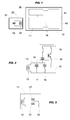
- the detection system comprises a detector of inductive proximity 10 and a target 20 that can be detected when it is located at proximity of the detector, that is to say in its detection zone.
- the detector 10 comprises an oscillating circuit 11, called the first oscillating circuit, which generates a detection signal 18 and processing means 40 which provides an output signal 41.
- the output signal is a binary signal that indicates the presence or absence of a target near the detector 10.
- the first oscillating circuit 11 is powered by an oscillator 30, for example a analog oscillator such as that shown in Figure 2 or a Namur type oscillator.
- This oscillator 30 is a current generator that sends to the first oscillating circuit 11 a current whose frequency must match the oscillation frequency of the first circuit oscillator 11.
- the oscillator 30 must not be an oscillator operating in oscillation forced.
- the processing means 40 comprise a detection stage loaded to amplify and shape the detection signal 18 received from the first oscillating circuit 11 and a processing unit to analyze this received signal and deduce the response from the detector.
- the processing means 40 also comprise an output stage which sets form and deliver the output signal 41 of the detection system, from the response developed by the processing unit.
- the first oscillating circuit 11 is composed of a coil 12 of inductance L which is connected in parallel with a variable capacitive circuit.
- the winding 12 is placed so that it can be influenced by a target placed near the detector 10.
- the variable capacitive circuit comprises a first capacitor 13 connected in parallel with a second capacitor 14, as well as a switch electronics 15 connected in series with the second capacitor 14.
- the first circuit oscillator 11 ' has a variable capacitive circuit which includes a first capacitor 13' connected in series with a second capacitor 14 'and an electronic switch 15 connected in parallel with the second capacitor 14 '.
- the electronic switch 15, which is either in an open state or a closed state, is controlled by a binary switching 19 which preferably emanates from the processing means 40.
- switch 15 may in particular include a transistor, for example of the MOS type, a triac, a thyristor, an electromechanical microsystem (MEMS) bimetallic, or others.
- MEMS electromechanical microsystem
- the first oscillating circuit 11 operates in free oscillation, that is to say that it is the value of the inductance L of the winding 12 and the value of the capacitance of the variable capacitive circuit which define the oscillation frequency F OSC of detector 10. It is therefore possible to vary this frequency thanks to the variable capacitive circuit.
- the switch 15 depending on whether the switch 15 is in the closed state or in the open state, it connects or isolates the second capacitor 14, 14 ', which modifies the value of the capacitance of the circuit capacitive variable between a value C 1 and a value C 2 .
- the values L C and C C are chosen so that the frequency F C is substantially equal to one or other of the two oscillation frequencies F OSC1 or F OSC2 .
- the first oscillating circuit 11 resonates with the second oscillating circuit 21 but only for one of the two oscillation frequencies F.
- OSC1 or F OSC2 the detection signal 18 can therefore be different according to the value of the oscillation frequency F OSC since, in the presence of a target 20, it is damped by only one of the two frequencies F OSC1 and F OSC2 .
- the winding 12 and the capacitors 13 and 14 are chosen to provide values of about 100KHz for F OSC1 and about 140KHz for F OSC2 .
- a tolerance of the order of 10% of the F C value can be perfectly tolerated to achieve proper operation of the detection system, which allows the use of inexpensive components and therefore not to penalize the system. manufacturing cost of the target 20.
- the operation of the detection system is as follows:
- the processing unit then verifies that the result of the comparison between the oscillation level V OSC of the detection signal 18 and the threshold V DET is in synchronism with the state of the switch 15 and therefore with the state of the switching order 19 sent by the processing means 40 (neglecting in particular possible delays in switching times).
- the processing unit In order for the processing unit to detect the presence of a target 20, it is necessary not only that the result of the comparison between the oscillation level V OSC and the threshold V DET change periodically, but also that these changes are synchronized with the switching order 19. In addition, any change in the periodicity of the switching command 19 must create an equivalent change in the periodicity of the detection signal 18. When the processing unit detects this synchronism, the processing means 40 then provide an output signal 41 signaling the presence of a target 20.
- the output signal 41 thus makes it possible to indicate that a target 20 has been detected (situation # 3 above), since he is able not to confuse a metal target any with the particular target as described above. This allows to respond very simply to the desired security function.
- the detection system could also provide additional information indicating that a target different metal from a target 20 was detected (situation 2), which could constitute a cause of alarm.
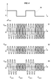
- the time interval between two consecutive changes of the switching order 19 is fixed, as shown in FIG. 4.
- variable time intervals between two consecutive changes of the order can be used for example alternations whose duration is not fixed but is calculated from a pseudo-random binary sequence stored inside the detector.
- the processing unit will then have to check the synchronism between the variations of the oscillation level Vosc and the variations of the switching order 19 to develop the output 41 of the detector, which improves the security of the system.
- the values of the frequencies F C , F OSC1 and F OSC2 are common for the different detectors and targets. However, one could also consider values F C , F OSC1 and F OSC2 that are personalized and specific to a given detection system, or to a set of given detection systems, which would be intended for example for a particular application. In such a case, a detector could be associated only with a target belonging to the same detection system or the same set of systems, further increasing the security of the system. Other combinations are obviously possible.
- the detector processing means may comprise two units of processing that each develop a distinct response to provide two signals of independent output, in order to be able to monitor a possible deterioration of one of these outputs (cut or shorted).
Landscapes
- Engineering & Computer Science (AREA)
- Computer Networks & Wireless Communication (AREA)
- Signal Processing (AREA)
- Geophysics And Detection Of Objects (AREA)
Applications Claiming Priority (2)
| Application Number | Priority Date | Filing Date | Title |
|---|---|---|---|
| FR0404994 | 2004-05-10 | ||
| FR0404994A FR2870062B1 (fr) | 2004-05-10 | 2004-05-10 | Systeme de direction inductif de securite |
Publications (1)
| Publication Number | Publication Date |
|---|---|
| EP1598951A1 true EP1598951A1 (de) | 2005-11-23 |
Family
ID=34939547
Family Applications (1)
| Application Number | Title | Priority Date | Filing Date |
|---|---|---|---|
| EP05103446A Withdrawn EP1598951A1 (de) | 2004-05-10 | 2005-04-27 | Induktives Sicherheitserkennungssystem |
Country Status (2)
| Country | Link |
|---|---|
| EP (1) | EP1598951A1 (de) |
| FR (1) | FR2870062B1 (de) |
Cited By (1)
| Publication number | Priority date | Publication date | Assignee | Title |
|---|---|---|---|---|
| EP1940043A1 (de) * | 2006-12-28 | 2008-07-02 | Lineas Y Cables, S.A. | System zur Übertragung von elektrischer Energie ohne Leiter |
Citations (3)
| Publication number | Priority date | Publication date | Assignee | Title |
|---|---|---|---|---|
| US4792965A (en) * | 1987-01-29 | 1988-12-20 | Morgan Harvey L | Oscillator system for detecting a selected one of a plurality of tuned circuits |
| JPH07153589A (ja) * | 1993-11-26 | 1995-06-16 | Sanyo Electric Co Ltd | 放電燈点灯装置 |
| US5962988A (en) * | 1995-11-02 | 1999-10-05 | Hubbell Incorporated | Multi-voltage ballast and dimming circuits for a lamp drive voltage transformation and ballasting system |
-
2004
- 2004-05-10 FR FR0404994A patent/FR2870062B1/fr not_active Expired - Fee Related
-
2005
- 2005-04-27 EP EP05103446A patent/EP1598951A1/de not_active Withdrawn
Patent Citations (3)
| Publication number | Priority date | Publication date | Assignee | Title |
|---|---|---|---|---|
| US4792965A (en) * | 1987-01-29 | 1988-12-20 | Morgan Harvey L | Oscillator system for detecting a selected one of a plurality of tuned circuits |
| JPH07153589A (ja) * | 1993-11-26 | 1995-06-16 | Sanyo Electric Co Ltd | 放電燈点灯装置 |
| US5962988A (en) * | 1995-11-02 | 1999-10-05 | Hubbell Incorporated | Multi-voltage ballast and dimming circuits for a lamp drive voltage transformation and ballasting system |
Non-Patent Citations (1)
| Title |
|---|
| PATENT ABSTRACTS OF JAPAN vol. 1995, no. 09 31 October 1995 (1995-10-31) * |
Cited By (1)
| Publication number | Priority date | Publication date | Assignee | Title |
|---|---|---|---|---|
| EP1940043A1 (de) * | 2006-12-28 | 2008-07-02 | Lineas Y Cables, S.A. | System zur Übertragung von elektrischer Energie ohne Leiter |
Also Published As
| Publication number | Publication date |
|---|---|
| FR2870062A1 (fr) | 2005-11-11 |
| FR2870062B1 (fr) | 2006-06-23 |
Similar Documents
| Publication | Publication Date | Title |
|---|---|---|
| EP0670505B1 (de) | Induktive Näherungssensor | |
| FR2919072A1 (fr) | Detecteur de proximite inductif a bobinages commutes. | |
| EP1160400B1 (de) | Mit Kontakt eines menschlichen Körpers arbeitende Schaltvorrichtung | |
| FR2949268A1 (fr) | Dispositif de detection d'entree et de reconnaissance de badges transpondeurs, systeme de surveillance le comprenant et procede de surveillance mis en oeuvre par ledit systeme | |
| CH669858A5 (de) | ||
| FR2775350A1 (fr) | Systeme detecteur pour controle d'acces et ensemble detecteur pour la mise en oeuvre d'un tel systeme | |
| FR3047808B1 (fr) | Procede de detection d'approche et/ou de contact d'une main d'un utilisateur vers une poignee de portiere de vehicule et dispositif de detection associe | |
| EP1301898A1 (de) | Passiver transponder mit niedrigem energieverbrauch | |
| EP0688152B1 (de) | Steuerungsschaltung und Anordnung für eine Niederdruckleuchtstofflampe | |
| FR2943190A1 (fr) | Dispositif de declenchement d'une action sur un ouvrant de vehicule automobile | |
| WO2011067084A1 (fr) | Prolongateur d'antenne rfid auto-parametrable | |
| FR2571908A1 (fr) | Dispositif commutateur de proximite | |
| WO2018154210A1 (fr) | Détermination de contacts parasites sur un capteur de détection d'approche | |
| FR2921959A1 (fr) | Dispositif de detection de presence d'un utilisateur par un vehicule automobile | |
| WO2003093074A1 (fr) | Systeme de commande de l'acces et/ou du demarrage d'un vehicule automobile avec moyens d'alerte pour l'utilisateur | |
| FR2778464A1 (fr) | Dispositif de controle de l'antenne d'un systeme prevu dans un vehicule automobile, notamment un systeme de blocage de conduite | |
| WO2016058656A1 (fr) | Procédé de détection d'approche et/ou de contact et dispositif associé | |
| WO2003021782A1 (fr) | Capteur de presence | |
| EP1211649B2 (de) | Einen Annäherungssensor enthaltender Fahrzeugtürgriff und mit einem handfreien Zugangssystem zusammenarbeitender Berührungssensor | |
| WO2002021455A1 (fr) | Procede de traitement de signaux de detection pour un vehicule automobile | |
| WO2008068412A1 (fr) | Dispositif electronique, destine a realiser la mesure et la detection de variations d'au moins un signal d'entree | |
| EP0575912A1 (de) | Verfahren und Vorrichtung zum Überprüfen der Funktionstüchtigkeit eines Meldesystems mit Aufnehmer | |
| FR2770563A1 (fr) | Dispositif de reconnaissance d'une cle engagee dans une serrure de vehicule automobile | |
| WO2019186002A1 (fr) | Dispositif de détection par induction d'intention de verrouillage ou de déverrouillage d'un ouvrant de véhicule automobile avec bobines primaire et secondaire | |
| FR2809759A1 (fr) | Dispositif de verrouillage automatise des acces a un vehicule automobile |
Legal Events
| Date | Code | Title | Description |
|---|---|---|---|
| PUAI | Public reference made under article 153(3) epc to a published international application that has entered the european phase |
Free format text: ORIGINAL CODE: 0009012 |
|
| AK | Designated contracting states |
Kind code of ref document: A1 Designated state(s): AT BE BG CH CY CZ DE DK EE ES FI FR GB GR HU IE IS IT LI LT LU MC NL PL PT RO SE SI SK TR |
|
| AX | Request for extension of the european patent |
Extension state: AL BA HR LV MK YU |
|
| 17P | Request for examination filed |
Effective date: 20051214 |
|
| AKX | Designation fees paid |
Designated state(s): AT BE BG CH CY CZ DE DK EE ES FI FR GB GR HU IE IS IT LI LT LU MC NL PL PT RO SE SI SK TR |
|
| STAA | Information on the status of an ep patent application or granted ep patent |
Free format text: STATUS: THE APPLICATION IS DEEMED TO BE WITHDRAWN |
|
| 18D | Application deemed to be withdrawn |
Effective date: 20060530 |