EP1598901B1 - Joint box for connecting electrical wires - Google Patents
Joint box for connecting electrical wires Download PDFInfo
- Publication number
- EP1598901B1 EP1598901B1 EP05009721.1A EP05009721A EP1598901B1 EP 1598901 B1 EP1598901 B1 EP 1598901B1 EP 05009721 A EP05009721 A EP 05009721A EP 1598901 B1 EP1598901 B1 EP 1598901B1
- Authority
- EP
- European Patent Office
- Prior art keywords
- electrical wires
- cover
- lock
- joint
- wall
- Prior art date
- Legal status (The legal status is an assumption and is not a legal conclusion. Google has not performed a legal analysis and makes no representation as to the accuracy of the status listed.)
- Expired - Lifetime
Links
- 238000005192 partition Methods 0.000 claims description 10
- 238000005304 joining Methods 0.000 description 4
- 229920003002 synthetic resin Polymers 0.000 description 4
- 239000000057 synthetic resin Substances 0.000 description 4
- 230000001012 protector Effects 0.000 description 3
- 238000003466 welding Methods 0.000 description 3
- 238000000465 moulding Methods 0.000 description 2
- 238000003825 pressing Methods 0.000 description 2
- 239000012141 concentrate Substances 0.000 description 1
- 238000002788 crimping Methods 0.000 description 1
- 238000005520 cutting process Methods 0.000 description 1
- 230000001419 dependent effect Effects 0.000 description 1
- 239000002184 metal Substances 0.000 description 1
Images


Classifications
-
- H—ELECTRICITY
- H01—ELECTRIC ELEMENTS
- H01R—ELECTRICALLY-CONDUCTIVE CONNECTIONS; STRUCTURAL ASSOCIATIONS OF A PLURALITY OF MUTUALLY-INSULATED ELECTRICAL CONNECTING ELEMENTS; COUPLING DEVICES; CURRENT COLLECTORS
- H01R4/00—Electrically-conductive connections between two or more conductive members in direct contact, i.e. touching one another; Means for effecting or maintaining such contact; Electrically-conductive connections having two or more spaced connecting locations for conductors and using contact members penetrating insulation
- H01R4/24—Connections using contact members penetrating or cutting insulation or cable strands
- H01R4/2416—Connections using contact members penetrating or cutting insulation or cable strands the contact members having insulation-cutting edges, e.g. of tuning fork type
- H01R4/242—Connections using contact members penetrating or cutting insulation or cable strands the contact members having insulation-cutting edges, e.g. of tuning fork type the contact members being plates having a single slot
- H01R4/2425—Flat plates, e.g. multi-layered flat plates
- H01R4/2429—Flat plates, e.g. multi-layered flat plates mounted in an insulating base
- H01R4/2433—Flat plates, e.g. multi-layered flat plates mounted in an insulating base one part of the base being movable to push the cable into the slot
-
- H—ELECTRICITY
- H01—ELECTRIC ELEMENTS
- H01R—ELECTRICALLY-CONDUCTIVE CONNECTIONS; STRUCTURAL ASSOCIATIONS OF A PLURALITY OF MUTUALLY-INSULATED ELECTRICAL CONNECTING ELEMENTS; COUPLING DEVICES; CURRENT COLLECTORS
- H01R13/00—Details of coupling devices of the kinds covered by groups H01R12/70 or H01R24/00 - H01R33/00
- H01R13/46—Bases; Cases
- H01R13/50—Bases; Cases formed as an integral body
- H01R13/501—Bases; Cases formed as an integral body comprising an integral hinge or a frangible part
-
- H—ELECTRICITY
- H01—ELECTRIC ELEMENTS
- H01R—ELECTRICALLY-CONDUCTIVE CONNECTIONS; STRUCTURAL ASSOCIATIONS OF A PLURALITY OF MUTUALLY-INSULATED ELECTRICAL CONNECTING ELEMENTS; COUPLING DEVICES; CURRENT COLLECTORS
- H01R12/00—Structural associations of a plurality of mutually-insulated electrical connecting elements, specially adapted for printed circuits, e.g. printed circuit boards [PCB], flat or ribbon cables, or like generally planar structures, e.g. terminal strips, terminal blocks; Coupling devices specially adapted for printed circuits, flat or ribbon cables, or like generally planar structures; Terminals specially adapted for contact with, or insertion into, printed circuits, flat or ribbon cables, or like generally planar structures
- H01R12/50—Fixed connections
- H01R12/59—Fixed connections for flexible printed circuits, flat or ribbon cables or like structures
- H01R12/61—Fixed connections for flexible printed circuits, flat or ribbon cables or like structures connecting to flexible printed circuits, flat or ribbon cables or like structures
- H01R12/613—Fixed connections for flexible printed circuits, flat or ribbon cables or like structures connecting to flexible printed circuits, flat or ribbon cables or like structures by means of interconnecting elements
- H01R12/616—Fixed connections for flexible printed circuits, flat or ribbon cables or like structures connecting to flexible printed circuits, flat or ribbon cables or like structures by means of interconnecting elements having contacts penetrating insulation for making contact with conductors, e.g. needle points
Definitions
- This invention relates to a joint box according to the preamble of claim 1 which is known from JPH7-298447.
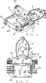
- Fig. 12 shows an embodiment of a joint box according to JP 11191446 A (Reference Patent 1).
- a joint box 51 includes a main box body 52 made of synthetic resin and a cover 54 covering a top opening 53 of the main box body 52.
- the cover 54 is formed through a thin hinge integrally with the main box body 52.
- Pressure-contact terminals 55 are provided in the main box body 52.
- the cover 54 is provided with projections 56 corresponding to the pressure-contact terminals 55 for pressing the electrical wires.
- the cover 54 moves around the hinge between a position of opening the main box body 52 and a position of covering the main box body 52.
- the cover 54 has a lock hole 74 and the main box body 52 has a lock projection 75.
- the lock hole 74 and the lock projection 75 are engaged with each other when the cover 54 covers the main box body 52.
- an electrical wire 57 with a male terminal is connected by pressure contact with the pressure-contact terminal 55.
- the male terminal projects from a front opening (not shown) of the main box body 52 , and is locked in a connector housing to be press-fitted with the front opening so as to structure a connector.
- two pressure-contact terminals 55 in the main box body 52 are arranged in parallel, and connected with each other by a horizontal connecting plate 58 so as to form a bus bar 59 for joining electrical wires 57.
- Two electrical wires 57 are joined with each other through the bus bar 59.
- Joining points (pressure-contact points) of the pressure-contact terminals 55 and the electrical wires 57 are covered by the cover 54 ( Fig. 12 ) for protection.
- Fig. 14 shows the other embodiment of the joint box by prior art (see Reference Patent 2)
- a joint box 61 includes a main box body 62 and a cover 63 made of synthetic resin, a bus bar 64 provided in the main box body 62, and an earth ground terminal 65 integrally continued to the bus bar 64 and projecting out of the main box body 62.
- the bus bar 64 has a plurality of pressure-contact terminals 66. Each electrical wire 67 is press-fitted into each pressure-contact terminal 66 and led from the both sides of the main box body 62 to an outside thereof. Each end of the electrical wires 67 is provided with a connector to be connected with an apparatus.
- the earth ground terminal 65 is screwed on a vehicle body so that each electrical wire 67 is joined by the bus bar 64 for grounding it to the vehicle body.
- the joint box 51, 61 by prior art can protect pressure-contact points of the electrical wires 57, 67 by the cover 54, 63.
- the other component such as a harness protector and a band clamp, is required for supporting the electrical wires and protecting them. Therefore, there are problems of an extra cost of the other component and additional operation for bundling the electrical wires.
- the joint box 51 having the main box body 52 and the cover 54 formed through the thin hinge integrally with the main box body 52, when the hinge is broken off, lock of the lock hole 74 and the lock projection 75 is unlocked and the cover 54 is fallen out of the main box body 52. Therefore, the terminals and electrical wires received in the joint box 51 are exposed possibly to contact to other apparatuses or short to each other or cause unstable contact of the terminal and the wires.
- object of this invention is to provide a joint box, which can bundle pressure contacted electrical wires and electrical wires not to be pressure-contacted easily and securely and furthermore can prevent a cover from falling out of a main box body when a hinge is broken off, and a wire bundling structure by using the joint box. How to attain the object of the present invention
- Such joint box includes a base unit having separately a joint portion for connecting electrical wires with each other and a wire bundle portion for passing the electric wires therethrough to bundle the electrical wires and a cover mounted on the base unit for covering the joint portion and the wire bundle portion.
- the electrical wires not to be joined can be positioned and held together with the joined electrical wire in the joint box without another component, such as the harness protector, and the band clamp. Cost of the another component can be reduced. Operation of passing and holding the electrical wire through the another component, and fixing the another component on the vehicle body is not required, so that operation of wiring electrical wires in the vehicle is made more effective.
- Another component for bundling the electrical wires is not required. Comparing the joint box by prior art, numbers of the electrical wires, types thereof and terminals for joining are reduced so that the joint box size is miniaturized and the cost is reduced.
- Fig. 1 shows one embodiment of a joint box according to the present invention.
- a joint box 1 includes a main box body 2 made of synthetic resin, a plurality of pressure-contact terminals 3 arranged in the main box body 2, a plurality of electric conductive metal bus bars formed by connecting the predetermined terminals with each other with a horizontal connecting plate (not shown), an earth ground terminal 4 being continued to a bus bar (not shown) at earth ground side, and a cover 5 made of synthetic resin for covering the main box body 2.
- a base unit 6 is structured with the main box body 2 and the bus bars including the pressure-contact terminals.
- the base unit 6 is divided into a joint portion 7 including the pressure-contact terminals 3 at a rear half thereof and a wire bundle portion 8 without the pressure-contact terminals 3 at a front half thereof.
- a front side is defined as a side of the earth ground terminal 4.
- the joint portion 7 has a groove 10 for arranging respective electrical wires 9 ( Fig. 9 ) in parallel and pressure-contact terminals 3 placed in the groove 10.
- the groove 10 is formed by surrounding with a bottom wall 11 of the main box body 2, a partition wall standing vertically from the bottom wall 11.
- the pressure-contact terminals 3 are fixed in the partition wall 12 by insert molding.
- the horizontal connecting plate (not shown) of the bus bar is molded inside the bottom wall 11 of the main box body 2 by insert molding.
- Both of side walls 13 are formed vertically at both ends in a direction of lengthwise of the groove 10.
- a half-round wire lead-out 14 is formed at a top end of the both side walls 13.
- the wire bundle portion 8 of the base unit 6 includes a wide rectangular gutter 15 (space) parallel to the groove 10 of the joint portion 7.
- the gutter 15 is surrounded with the partition wall 12-1 at the front end of the joint portion 7, the bottom wall 11 of the main box body 2 and a vertical front wall 16 at the earth ground terminal side.
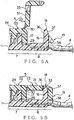
- the partition wall 12-1 is provided with a pair of right-and-left lock projections 17 corresponding to the cover 5, projecting to an inside of the gutter 15.
- a pair of right-and-left second lock projections 18 is provided at a top edge of the front wall 16 at a front end to project upwardly.
- a pair of right-and-left first lock projections 19 is provided at an outer surface of the front wall 16.
- a pair of lock projections 21 is provided on a rear wall 20 at a rear end of the joint portion 7 symmetrically against the lock projections 17 of the partition wall 12-1.
- the cover 5 is locked with the six lock projections 17, 19, 21.
- Respective lock projections 17, 19, 21 have a slant surface "a" at a top side thereof and a lock surface "b" at a bottom side thereof.
- the first lock projection 19 provided at the main box body 2 projects from the outer surface of the front wall 16 along the surface of the bottom wall 11.
- the surface 38 of the first lock projection 19 in the vicinity of the bottom wall 11 is formed vertical to the front wall 16.
- the second lock projection 18 projects from the top edge, apart from the bottom wall 11, of the front wall 16 along a surface of the front wall 16.
- An inner surface 36 of the main box body 2 extends in parallel to the surface of the front wall 16. Thereby, the surface 38 of the first lock projection 19 in the vicinity of the bottom wall 11 intersects with the inner surface 36 of the box man body 2 at the second lock projection 18.
- An outer surface 37 of the main box body 2 at the second lock projection 18 is tapered gradually toward an inside of the main box body 2 in accordance with a distance from the bottom wall 11.
- the cover 5 includes a large first cover portion 22 for covering the joint portion 7 and a small second cover portion 23 for covering the wire bundle portion 8.
- the first cover portion 22 is formed into an L-shape with a horizontal top wall 24 and a vertical rear wall 25. A width of the top wall 24 is slightly narrower than that of the rear wall 25.
- the electrical wires 9 ( Fig. 9 ) can be led to outside from both of right-and-left edge portions 26.
- the rear wall 25 is provided with a pair of right-and-left rectangular lock holes 27 corresponding to the lock projections 21 on the rear wall 20 of the main box body 2.
- the first cover portion 22 has flexible rims 28 close to the lock holes 27.
- a pair of right-and-left lock rims 29 corresponding to the lock projections 17 on the partition wall 12-1 at the front end of the joint portion 7 is formed downwardly and vertically at a front edge of the top wall 24.
- a flexible thin hinge 30 is formed integrally with the top wall 24 between the pair of lock rims 29 and at a center of the front edge of the top wall 24.
- the hinge 30 is connected integrally with the second cover portion 23.
- the second cover portion 23 can rotate freely about the hinge 30 in open/close directions. In Fig. 11 , the second cover portion 23 is closed. Width in a direction perpendicular to a front/rear direction of the second cover portion 23 is wider than that of the top wall 24 of the first cover portion 22 and the same as that of the rear wall 25 of the first cover portion 22.
- the second cover portion 23 has a top wall 31, which looks up when closed, and a low front wall 32 continued vertically to a front end of the top wall 31. A rear end of the top wall 31 is continued to the hinge 30.
- the second cover portion 23 is provided at a front side of the top wall 31 with a pair of right-and-left rectangular second lock holes (second lock portion) 33 corresponding to the second lock projections 18 extending upwardly at the top edge of the front wall 16.
- the second cover portion 23 is also provided at the front wall 32 with a pair of right-and-left rectangular first lock holes (first lock portion) 34 corresponding to the first lock projections 19 of the front wall 16.
- a rim 35 surrounding the first lock hole 34 is formed flexible.
- the front wall 32 has a cutout (not shown) for passing the earth ground terminal 4 therethrough between the rims 35.
- the first cover portion 22 of the cover 5 is provided on an inner surface thereof with ribs (not shown) for pressing electrical wires corresponding to respective grooves 10 of the joint portion 7 of the base unit 6 integrally, and recesses (not shown) corresponding to the pressure-contact terminals 3 at a middle in a direction of lengthwise of the rib.
- the earth ground terminal 4 includes a wide base plate 41, a rim 42 standing around the base plate 41, a hole 43 being opened at the base plate 41 for fixing and a lead 44 being bent downward at a front end of the base plate 41.
- Fig. 6 shows a vertical sectional view of the base unit 6.
- the base plate 41 of the earth ground terminal 4 extends in the bottom wall 11 of the wire bundle portion 8 as an extension 45 being integrally continued to a U-shape first bus bar 46.
- the first bus bar 46 continues to the pressure-contact terminals 3-1, 3-3 in a first line and a third line from a front side.
- a second bus bar (not shown), which is the other independent bus bar with an inverted U-shape, continues to the pressure-contact terminals 3-2, 3-4 in a second line and a fourth line from the front side.
- the pressure-contact terminal 3 includes a pair of right-and-left contact pieces 3a having a blade for cutting a wire cover at a top thereof, and a slot 3b for press-fitting the electrical wire between the contact pieces 3a.
- Each electrical wire 9 is press-fitted into each pressure-contact terminal 3.
- the pressure-contact terminals 3-2, 3-4 continued to the second bus bar are connected with the electrical wires 9 connected to a positive electrode.
- the pressure-contact terminals 3-1, 3-3 continued to the first bus bar 46 are connected with the electrical wires 9 connected to a negative electrode and connected through the earth ground terminal 4 with an earth ground of a vehicle body.
- the joint box 1 is assembled as followings.
- the electrical wires 9 are press-fitted into the pressure-contact terminals 3 provided in the joint portion 7 with a predetermined form.
- the other ends of some of the pressure-fitted electrical wires 9 are folded and received at the wire bundle portion 8.
- Electrical wires 40 which are not press-fitted, are received at the wire bundle portion 8.
- the second lock projection 18 is engaged with the second lock hole 33. Since the outer surface 37 of the second lock projection 18 is tapered gradually to the inside of main box body 2 in accordance with a distance from the bottom wall 11, the second cover portion 23 is mounted on the main box body 2 by that the outer surface 37 of the second lock projection 18 is not an obstacle against the second lock hole 33. Thus, the joint box 1 is assembled.
- the second cover portion 23 is possibly dismounted from the main box body 2.
- the inner surface 36 of the second lock projection 18 provided at the main box body 2 extends in parallel to the surface of the front wall 16.
- the surface 38 in the vicinity of the bottom wall 11 of the first lock projection 19 provided at the main box body 2 intersects perpendicularly with the front wall 16.
- the cover 5 is divided into two covers 22, 23.
- the cover 5 can be divided into more than two.
- the plurality of covers can be provided respectively with lock holes and the main box body 2 is provided with lock projections engaged with the lock holes.
- at least one of the plurality of the covers is provided with lock holes and the main box body 2 is provided with lock projections engaging with the lock holes.
- respective electrical wires 9 is placed in the each groove 10 at the joint portion 7 of the base unit 6 without the cover 5.
- Each electrical wire 9 is press-fitted into each pressure-contact terminal 3 by a pressure-contact jig (not shown) .
- one of two rear-half electrical wires 9-1 is connected with the second bus bar as the positive electrode.
- the other of two rear-half electrical wires 9 is connected with the first bus bar as the positive electrode.
- One of two front-half electrical wires 9-2 is connected with the second bus bar as the positive electrode, and the other is connected with the first bus bar as the negative electrode, which is continued to the earth ground terminal 4.
- the first cover portion 22 of the cover 5 is secured to cover the joint portion 7 for protecting.
- the electrical wires 9 are pressed and secured to the main box body 2 by the right/left edges of the first cover portion 22 as mentioned above. Thereby, it is prevented that a pulling force on the electrical wires 9 is transformed to pressure-contact points (connecting points of the pressure-contact terminals 3 and the electrical wires 9).
- the first cover portion 22 is locked on the main box body 2 by the lock projections 17, 21 and lock hole/rim 27, 29 at the front and the rear of the main box body 2.
- the second cover portion 23 opens continuously.
- not-press-fitted electrical wires 40 formed straight and a part of the press-fitted electrical wires 9-2 folded into U-shape are placed at the wire bundle portion of the base unit 6, and the second cover portion 23 is locked.
- the second cover portion 23 is positioned by the second lock projection 18 and the second lock hole 33, and locked securely by the first lock projection 19 and the first lock hole 34.
- the electrical wires 40, 9-2 are passed through the wire bundle portion 8, not fixed therein (movable in a direction of lengthwise of the electrical wire and held in a radial direction unmovable). Electrical wires having various diameters can be used as the electrical wires 40.
- the electrical wires 9 to be press-fitted and the electrical wires 40 not to be press-fitted are wired in the joint box 1 and held therein by locking the cover 5.
- the electrical wires 9, 40 can be bundled in one joint box 1, so that a harness protector by prior art can be eliminated and cost of components is reduced.
- the directions of leading the four electrical wires 9-2 can be arranged to one direction (left direction in Fig. 10 ) so as to concentrate a connection with a connector located in the same direction.
- each two led-out electrical wires 9-2 are connected at the ends thereof with each connector (not shown) .
- the ends of the electrical wires 9-1 can be connected with connectors, which are connected with an apparatus and the other connectors of a wire harness.
- the electrical wires 9 to be press-fitted should be secured ideally without moving them from the position of press-fitting them in view of quality. Therefore, according to the present invention, after press-fitting the electrical wires 9, the first cover portion 22 is mounted soon so as to clamp the electrical wires 9 between the joint portion 7 and the first cover portion 22 for preventing loading a tension force on the pressure-contact terminals 3. In the other operation, the other electrical wires 40 are received at the wire bundle portion 8 and the second cover portion 23 is locked.
- the press-fitted electrical wires 9 and the electrical wires 40 at the wire bundle portion 8 can be covered at once with a separated cover (not shown) not through the hinge 30.
- a separated cover not shown
- any operation unrelated with press-fitting should be separated so that two operations of wiring the electrical wires 9 and 40 are separated in the present invention.
- the cover 5 by connecting the cover portions 22, 23 through the hinge 30 according to the present invention is effective for such operations.
- the cover 5 For covering the joint portion 7 and the wire bundle portion 8 of the base unit 6 at once by the cover 5, after press-fitting the electrical wires 9 at the joint portion 7 and passing the other electrical wires 40 through the wire bundle portion 8, the cover 5 is locked on the base unit 6. Or, after press-fitting the electrical wires 9 at the joint portion 7, and passing the only press-fitted electrical wires 9-2 by folding them into U-shape through the wire bundle portion 8 , the cover 5 is locked on the base unit 6. Or, after press-fitting the electrical wires 9 at the joint portion 7, and passing the press-fitted electrical wires 9-2 by folding them into U-shape and the other electrical wires 40 through the wire bundle portion 8, the cover 5 is locked on the base unit 6.
- a cover is not limited only the cover 5 with hinge 30 according to this embodiment, but also a cover having one wide wall (not shown). In the cover having one wide wall, the lock projection 17 is not required on the partition wall 12-1 inside the wire bundle portion 8.
- lock projections 17, 19, 21 and lock rim 29 or lock holes 27, 34 are used for locking the cover 5 on the base unit 6.
- Locking devices are not limited them, and for example, a flexible lock projection or a blind lock hole, a recess, a groove for engaging or a step for engaging can be used.
- lock projections can be provided on the main box body 2 or the cover 5, and lock holes can be provided on the main box body 2 or the cover 5.
- the first cover portion 22 for the joint portion 7 and the second cover portion 23 for the wire bundle portion 8 can be formed separately without the hinge 30.
- the cover portions 22 and 23 require respective locking devices (providing lock rims at a rear end of the second cover portion 23) so that a structure thereof becomes complicated and a size thereof becomes larger.
- two electrical wires 9-1 and two electrical wires 9-2 are arranged adjacently and respective pressure-contact terminals of the first bus bar and the second bus bar are arranged alternately.
- respective pressure-contact terminals 3 of the first bus bar can be arranged adjacently and respective pressure-contact terminals 3 of the second bus bar can be arranged adjacently.
- Number of the electrical wires 9, 40 and pressure-contact terminals 3 can be determined according to a joint circuit.
- the directions of leading the electrical wires 9 from the base unit 6 are not limited two directions of right and left, and can be three directions of right, left and rear.
- a wire holding groove (not shown) going rearward and perpendicular to the grooves 10 for holding the electrical wires 9 in the directions of right and left is provided at a rear-half of the joint portion 7, and a pressure-contact terminal is provided in the wire holding groove.
- the electrical wire 9 is bent perpendicularly and wired and press-fitted in the grooves so as to be led in a perpendicular direction between right and rear or left and rear.
- grooves like half-round wire lead-outs 14 of the main box body 2 can be provided at right/left ends of the first cover portion 22 for clamping the electrical wires 9.
- a diameter of hole combined with the top and bottom half-round wire lead-outs 14 shall be smaller than that of the electrical wires 9.
- a crimp contact terminal or welding terminal (not shown) can be provided integrally or separately at the bus bar, and instead of press-fitting, core wire (conductive portion) of the electrical wire 9 can be joined with the terminal by crimping or welding.
- the pressure-contact terminal, the crimp terminal and welding terminal are called a joining terminal generally.
- the earth ground terminal 4 cannot be formed only into a flat plate shape, but also a tab shape, a female-shape and the like.
Landscapes
- Connection Or Junction Boxes (AREA)
Description
- This invention relates to a joint box according to the preamble of
claim 1 which is known from JPH7-298447. -
Fig. 12 shows an embodiment of a joint box according toJP 11191446 A - A
joint box 51 includes amain box body 52 made of synthetic resin and acover 54 covering a top opening 53 of themain box body 52. Thecover 54 is formed through a thin hinge integrally with themain box body 52. Pressure-contact terminals 55 are provided in themain box body 52. Thecover 54 is provided withprojections 56 corresponding to the pressure-contact terminals 55 for pressing the electrical wires. - The
cover 54 moves around the hinge between a position of opening themain box body 52 and a position of covering themain box body 52. Thecover 54 has alock hole 74 and themain box body 52 has alock projection 75. Thelock hole 74 and thelock projection 75 are engaged with each other when thecover 54 covers themain box body 52. - In the embodiment, an
electrical wire 57 with a male terminal (Fig. 13 ) is connected by pressure contact with the pressure-contact terminal 55. The male terminal (not shown) projects from a front opening (not shown) of themain box body 52 , and is locked in a connector housing to be press-fitted with the front opening so as to structure a connector. - As shown in
Fig. 13 , two pressure-contact terminals 55 in themain box body 52 are arranged in parallel, and connected with each other by a horizontal connectingplate 58 so as to form abus bar 59 for joiningelectrical wires 57. Twoelectrical wires 57 are joined with each other through thebus bar 59. Joining points (pressure-contact points) of the pressure-contact terminals 55 and theelectrical wires 57 are covered by the cover 54 (Fig. 12 ) for protection. -
Fig. 14 shows the other embodiment of the joint box by prior art (see Reference Patent 2) - A
joint box 61 includes amain box body 62 and acover 63 made of synthetic resin, abus bar 64 provided in themain box body 62, and anearth ground terminal 65 integrally continued to thebus bar 64 and projecting out of themain box body 62. - The
bus bar 64 has a plurality of pressure-contact terminals 66. Eachelectrical wire 67 is press-fitted into each pressure-contact terminal 66 and led from the both sides of themain box body 62 to an outside thereof. Each end of theelectrical wires 67 is provided with a connector to be connected with an apparatus. Theearth ground terminal 65 is screwed on a vehicle body so that eachelectrical wire 67 is joined by thebus bar 64 for grounding it to the vehicle body. - Reference Patents are:
-
Reference Patent 1, Japan Patent Application No.H11-191446 -
Reference Patent 2, Japan Patent Application No.2001-155792 -
Reference Patent 3, Japan Patent Application No.H10-285742 - The
joint box electrical wires cover joint box - For placing
electrical wires joint box - In the
joint box 51 having themain box body 52 and thecover 54 formed through the thin hinge integrally with themain box body 52, when the hinge is broken off, lock of thelock hole 74 and thelock projection 75 is unlocked and thecover 54 is fallen out of themain box body 52. Therefore, the terminals and electrical wires received in thejoint box 51 are exposed possibly to contact to other apparatuses or short to each other or cause unstable contact of the terminal and the wires. - To overcome the above problem, object of this invention is to provide a joint box, which can bundle pressure contacted electrical wires and electrical wires not to be pressure-contacted easily and securely and furthermore can prevent a cover from falling out of a main box body when a hinge is broken off, and a wire bundling structure by using the joint box. How to attain the object of the present invention
- In order to attain the object of the present invention, a joint box according to
claim 1 is defined. Preferred embodiments of the invention are further provided by the dependent claims. Such joint box
includes a base unit having separately a joint portion for connecting electrical wires with each other and a wire bundle portion for passing the electric wires therethrough to bundle the electrical wires and a cover mounted on the base unit for covering the joint portion and the wire bundle portion. - According to the aspect of the present invention, the electrical wires not to be joined can be positioned and held together with the joined electrical wire in the joint box without another component, such as the harness protector, and the band clamp. Cost of the another component can be reduced. Operation of passing and holding the electrical wire through the another component, and fixing the another component on the vehicle body is not required, so that operation of wiring electrical wires in the vehicle is made more effective.
- According to the aspect of the present invention, another component for bundling the electrical wires is not required. Comparing the joint box by prior art, numbers of the electrical wires, types thereof and terminals for joining are reduced so that the joint box size is miniaturized and the cost is reduced.
- The above and other objects and features of this invention will become more apparent from the following description taken in conjunction with the accompanying drawings.
-
Fig. 1 is an exploded perspective view of an embodiment of a joint box according to the present invention; -
Fig. 2 is a perspective view of the joint box shown inFig. 1 ; -
Fig. 3 is a plan view of the joint box shown inFig. 1 ; -
Fig. 4A is a cross-sectional view taking along XA-XA inFig. 2 ; -
Fig. 4B is a cross-sectional view taking along XB-XB inFig. 3 ; -
Fig. 5A is a cross-sectional view taking along YA-YA inFig. 2 ; -
Fig. 5B is a cross-sectional view taking along YB-YB inFig. 3 ; -
Fig. 6 is a cross-sectional view of a base unit of the joint box inFig. 1 ; -
Fig. 7 is a cross-sectional view showing a condition that a hinge shown inFig. 5B is broken; -
Fig. 8 is a plan view of the base unit, electrical wires wired at a joint portion of the base unit; -
Fig. 9 is a plan view of the base unit covered by a first cover portion of a cover; -
Fig. 10 is a plan view of the base unit, in which the electrical wires are bundled at a wire bundle portion, covered by a second cover portion; -
Fig. 11 is a perspective view of the base unit covered by the cover (an electrical wire bundle structure by the joint box); -
Fig. 12 is a perspective view of an example of a joint box by prior art; -
Fig. 13 is a perspective view of pressure-contact terminals of a bus bar by prior art in which electrical wires are press-fitted; and -
Fig. 14 is a perspective view of another example of a joint box by prior art. -
Fig. 1 shows one embodiment of a joint box according to the present invention. - A
joint box 1 includes amain box body 2 made of synthetic resin, a plurality of pressure-contact terminals 3 arranged in themain box body 2, a plurality of electric conductive metal bus bars formed by connecting the predetermined terminals with each other with a horizontal connecting plate (not shown), anearth ground terminal 4 being continued to a bus bar (not shown) at earth ground side, and acover 5 made of synthetic resin for covering themain box body 2. - A
base unit 6 is structured with themain box body 2 and the bus bars including the pressure-contact terminals. Thebase unit 6 is divided into ajoint portion 7 including the pressure-contact terminals 3 at a rear half thereof and awire bundle portion 8 without the pressure-contact terminals 3 at a front half thereof. In this embodiment, a front side is defined as a side of theearth ground terminal 4. - The
joint portion 7 has agroove 10 for arranging respective electrical wires 9 (Fig. 9 ) in parallel and pressure-contact terminals 3 placed in thegroove 10. Thegroove 10 is formed by surrounding with abottom wall 11 of themain box body 2, a partition wall standing vertically from thebottom wall 11. The pressure-contact terminals 3 are fixed in the partition wall 12 by insert molding. The horizontal connecting plate (not shown) of the bus bar is molded inside thebottom wall 11 of themain box body 2 by insert molding. Both ofside walls 13 are formed vertically at both ends in a direction of lengthwise of thegroove 10. A half-round wire lead-out 14 is formed at a top end of the bothside walls 13. - The
wire bundle portion 8 of thebase unit 6 includes a wide rectangular gutter 15 (space) parallel to thegroove 10 of thejoint portion 7. The gutter 15 is surrounded with the partition wall 12-1 at the front end of thejoint portion 7, thebottom wall 11 of themain box body 2 and a verticalfront wall 16 at the earth ground terminal side. - The partition wall 12-1 is provided with a pair of right-and-
left lock projections 17 corresponding to thecover 5, projecting to an inside of the gutter 15. A pair of right-and-leftsecond lock projections 18 is provided at a top edge of thefront wall 16 at a front end to project upwardly. A pair of right-and-leftfirst lock projections 19 is provided at an outer surface of thefront wall 16. A pair oflock projections 21 is provided on arear wall 20 at a rear end of thejoint portion 7 symmetrically against thelock projections 17 of the partition wall 12-1. Thecover 5 is locked with the sixlock projections Respective lock projections - As shown in
Fig. 4A , thefirst lock projection 19 provided at themain box body 2 projects from the outer surface of thefront wall 16 along the surface of thebottom wall 11. Thesurface 38 of thefirst lock projection 19 in the vicinity of thebottom wall 11 is formed vertical to thefront wall 16. As shown inFig. 5A , thesecond lock projection 18 projects from the top edge, apart from thebottom wall 11, of thefront wall 16 along a surface of thefront wall 16. Aninner surface 36 of themain box body 2 extends in parallel to the surface of thefront wall 16. Thereby, thesurface 38 of thefirst lock projection 19 in the vicinity of thebottom wall 11 intersects with theinner surface 36 of thebox man body 2 at thesecond lock projection 18. - An
outer surface 37 of themain box body 2 at thesecond lock projection 18 is tapered gradually toward an inside of themain box body 2 in accordance with a distance from thebottom wall 11. - The
cover 5 includes a largefirst cover portion 22 for covering thejoint portion 7 and a smallsecond cover portion 23 for covering thewire bundle portion 8. - The
first cover portion 22 is formed into an L-shape with a horizontaltop wall 24 and a verticalrear wall 25. A width of thetop wall 24 is slightly narrower than that of therear wall 25. The electrical wires 9 (Fig. 9 ) can be led to outside from both of right-and-leftedge portions 26. Therear wall 25 is provided with a pair of right-and-left rectangular lock holes 27 corresponding to thelock projections 21 on therear wall 20 of themain box body 2. Thefirst cover portion 22 hasflexible rims 28 close to the lock holes 27. A pair of right-and-left lock rims 29 corresponding to thelock projections 17 on the partition wall 12-1 at the front end of thejoint portion 7 is formed downwardly and vertically at a front edge of thetop wall 24. - A flexible
thin hinge 30 is formed integrally with thetop wall 24 between the pair of lock rims 29 and at a center of the front edge of thetop wall 24. Thehinge 30 is connected integrally with thesecond cover portion 23. Thesecond cover portion 23 can rotate freely about thehinge 30 in open/close directions. InFig. 11 , thesecond cover portion 23 is closed. Width in a direction perpendicular to a front/rear direction of thesecond cover portion 23 is wider than that of thetop wall 24 of thefirst cover portion 22 and the same as that of therear wall 25 of thefirst cover portion 22. - The
second cover portion 23 has atop wall 31, which looks up when closed, and a lowfront wall 32 continued vertically to a front end of thetop wall 31. A rear end of thetop wall 31 is continued to thehinge 30. Thesecond cover portion 23 is provided at a front side of thetop wall 31 with a pair of right-and-left rectangular second lock holes (second lock portion) 33 corresponding to thesecond lock projections 18 extending upwardly at the top edge of thefront wall 16. Thesecond cover portion 23 is also provided at thefront wall 32 with a pair of right-and-left rectangular first lock holes (first lock portion) 34 corresponding to thefirst lock projections 19 of thefront wall 16. Arim 35 surrounding thefirst lock hole 34 is formed flexible. Thefront wall 32 has a cutout (not shown) for passing theearth ground terminal 4 therethrough between therims 35. - The
first cover portion 22 of thecover 5 is provided on an inner surface thereof with ribs (not shown) for pressing electrical wires corresponding torespective grooves 10 of thejoint portion 7 of thebase unit 6 integrally, and recesses (not shown) corresponding to the pressure-contact terminals 3 at a middle in a direction of lengthwise of the rib. - Right/left ends of the respective ribs intersect perpendicularly with
ribs 39 extending in a front-to-rear direction at right and left ends of thefirst cover portion 22. Theribs 39 at right and left ends of thefirst cover portion 22 go inside the right and leftside walls 13 of thebase unit 6 for clamping the electrical wires 9 (Fig. 9 ) between the half-round wire lead-out 14 and them. - The
earth ground terminal 4 includes awide base plate 41, arim 42 standing around thebase plate 41, ahole 43 being opened at thebase plate 41 for fixing and a lead 44 being bent downward at a front end of thebase plate 41. -
Fig. 6 shows a vertical sectional view of thebase unit 6. Thebase plate 41 of theearth ground terminal 4 extends in thebottom wall 11 of thewire bundle portion 8 as anextension 45 being integrally continued to a U-shapefirst bus bar 46. Thefirst bus bar 46 continues to the pressure-contact terminals 3-1, 3-3 in a first line and a third line from a front side. A second bus bar (not shown), which is the other independent bus bar with an inverted U-shape, continues to the pressure-contact terminals 3-2, 3-4 in a second line and a fourth line from the front side. - The pressure-
contact terminal 3 includes a pair of right-and-left contact pieces 3a having a blade for cutting a wire cover at a top thereof, and aslot 3b for press-fitting the electrical wire between the contact pieces 3a. - Each
electrical wire 9 is press-fitted into each pressure-contact terminal 3. The pressure-contact terminals 3-2, 3-4 continued to the second bus bar are connected with theelectrical wires 9 connected to a positive electrode. The pressure-contact terminals 3-1, 3-3 continued to thefirst bus bar 46 are connected with theelectrical wires 9 connected to a negative electrode and connected through theearth ground terminal 4 with an earth ground of a vehicle body. - The
joint box 1 is assembled as followings. Theelectrical wires 9 are press-fitted into the pressure-contact terminals 3 provided in thejoint portion 7 with a predetermined form. By engaging thelock projections 21 and the lock holes 27, and engaging thelock projections 17 and the lock rims 29, thefirst cover portion 22 is locked on themain box body 2. The other ends of some of the pressure-fittedelectrical wires 9 are folded and received at thewire bundle portion 8.Electrical wires 40, which are not press-fitted, are received at thewire bundle portion 8. By rotating thesecond cover portion 23 about thehinge 30, and engaging thefirst lock projections 19 and the first lock holes 34, thesecond lock projections 18 and the second lock holes 33, thesecond cover portion 23 is locked on themain box body 2. - When the
second cover portion 23 is mounted on themain box body 2, thesecond lock projection 18 is engaged with thesecond lock hole 33. Since theouter surface 37 of thesecond lock projection 18 is tapered gradually to the inside ofmain box body 2 in accordance with a distance from thebottom wall 11, thesecond cover portion 23 is mounted on themain box body 2 by that theouter surface 37 of thesecond lock projection 18 is not an obstacle against thesecond lock hole 33. Thus, thejoint box 1 is assembled. - When the
hinge 30 is broken off to separate thefirst cover portion 22 and thesecond cover portion 23 as shown inFig. 7 , thesecond cover portion 23 is possibly dismounted from themain box body 2. Theinner surface 36 of thesecond lock projection 18 provided at themain box body 2 extends in parallel to the surface of thefront wall 16. Thesurface 38 in the vicinity of thebottom wall 11 of thefirst lock projection 19 provided at themain box body 2 intersects perpendicularly with thefront wall 16. Thereby, The pair ofsecond lock projections 18 provided at themain box body 2 is locked continuously with the pair ofsecond lock hole 33 provided at thesecond cover portion 23. Also, thefirst lock projection 19 is locked continuously with thefirst lock hole 34. - Therefore, when the
hinge 30 is broken off, thefirst cover portion 22 and thesecond cover portion 23 of thecover 5 are prevented from falling off from themain box body 2. - By connecting the
first cover portion 22 and thesecond cover portion 23, which have different utilities, through thehinge 30, number of components of thecover 5 can be reduced. - In this embodiment, the
cover 5 is divided into twocovers cover 5 can be divided into more than two. The plurality of covers can be provided respectively with lock holes and themain box body 2 is provided with lock projections engaged with the lock holes. According to the present invention, at least one of the plurality of the covers is provided with lock holes and themain box body 2 is provided with lock projections engaging with the lock holes. - An electrical wire bundling structure having the above
joint box 1 will be described herein. - As shown in
Fig. 8 , respectiveelectrical wires 9 is placed in the eachgroove 10 at thejoint portion 7 of thebase unit 6 without thecover 5. Eachelectrical wire 9 is press-fitted into each pressure-contact terminal 3 by a pressure-contact jig (not shown) . In this embodiment, one of two rear-half electrical wires 9-1 is connected with the second bus bar as the positive electrode. The other of two rear-halfelectrical wires 9 is connected with the first bus bar as the positive electrode. One of two front-half electrical wires 9-2 is connected with the second bus bar as the positive electrode, and the other is connected with the first bus bar as the negative electrode, which is continued to theearth ground terminal 4. - After press-fitting the
electrical wires 9, only thefirst cover portion 22 of thecover 5 is secured to cover thejoint portion 7 for protecting. Theelectrical wires 9 are pressed and secured to themain box body 2 by the right/left edges of thefirst cover portion 22 as mentioned above. Thereby, it is prevented that a pulling force on theelectrical wires 9 is transformed to pressure-contact points (connecting points of the pressure-contact terminals 3 and the electrical wires 9). Thefirst cover portion 22 is locked on themain box body 2 by thelock projections rim main box body 2. Thesecond cover portion 23 opens continuously. - After the
first cover portion 22 is locked, not-press-fittedelectrical wires 40 formed straight and a part of the press-fitted electrical wires 9-2 folded into U-shape are placed at the wire bundle portion of thebase unit 6, and thesecond cover portion 23 is locked. Thesecond cover portion 23 is positioned by thesecond lock projection 18 and thesecond lock hole 33, and locked securely by thefirst lock projection 19 and thefirst lock hole 34. Theelectrical wires 40, 9-2 are passed through thewire bundle portion 8, not fixed therein (movable in a direction of lengthwise of the electrical wire and held in a radial direction unmovable). Electrical wires having various diameters can be used as theelectrical wires 40. - Thus, the
electrical wires 9 to be press-fitted and theelectrical wires 40 not to be press-fitted are wired in thejoint box 1 and held therein by locking thecover 5. Theelectrical wires joint box 1, so that a harness protector by prior art can be eliminated and cost of components is reduced. - By holding the press-fitted two electrical wires 9-2 folded into U-shape, the directions of leading the four electrical wires 9-2 can be arranged to one direction (left direction in
Fig. 10 ) so as to concentrate a connection with a connector located in the same direction. For example, each two led-out electrical wires 9-2 are connected at the ends thereof with each connector (not shown) . The ends of the electrical wires 9-1 can be connected with connectors, which are connected with an apparatus and the other connectors of a wire harness. - The
electrical wires 9 to be press-fitted should be secured ideally without moving them from the position of press-fitting them in view of quality. Therefore, according to the present invention, after press-fitting theelectrical wires 9, thefirst cover portion 22 is mounted soon so as to clamp theelectrical wires 9 between thejoint portion 7 and thefirst cover portion 22 for preventing loading a tension force on the pressure-contact terminals 3. In the other operation, the otherelectrical wires 40 are received at thewire bundle portion 8 and thesecond cover portion 23 is locked. - At the position of press-fitting the
electrical wires 9, the press-fittedelectrical wires 9 and theelectrical wires 40 at thewire bundle portion 8 can be covered at once with a separated cover (not shown) not through thehinge 30. In the press-fitting operation which requires carefulness, any operation unrelated with press-fitting should be separated so that two operations of wiring theelectrical wires cover 5 by connecting thecover portions hinge 30 according to the present invention is effective for such operations. - For covering the
joint portion 7 and thewire bundle portion 8 of thebase unit 6 at once by thecover 5, after press-fitting theelectrical wires 9 at thejoint portion 7 and passing the otherelectrical wires 40 through thewire bundle portion 8, thecover 5 is locked on thebase unit 6. Or, after press-fitting theelectrical wires 9 at thejoint portion 7, and passing the only press-fitted electrical wires 9-2 by folding them into U-shape through thewire bundle portion 8 , thecover 5 is locked on thebase unit 6. Or, after press-fitting theelectrical wires 9 at thejoint portion 7, and passing the press-fitted electrical wires 9-2 by folding them into U-shape and the otherelectrical wires 40 through thewire bundle portion 8, thecover 5 is locked on thebase unit 6. - A cover is not limited only the
cover 5 withhinge 30 according to this embodiment, but also a cover having one wide wall (not shown). In the cover having one wide wall, thelock projection 17 is not required on the partition wall 12-1 inside thewire bundle portion 8. - According to the above embodiment, the
lock projections cover 5 on thebase unit 6. Locking devices are not limited them, and for example, a flexible lock projection or a blind lock hole, a recess, a groove for engaging or a step for engaging can be used. Also, lock projections can be provided on themain box body 2 or thecover 5, and lock holes can be provided on themain box body 2 or thecover 5. - The
first cover portion 22 for thejoint portion 7 and thesecond cover portion 23 for thewire bundle portion 8 can be formed separately without thehinge 30. In this case, thecover portions - In the above embodiment, two electrical wires 9-1 and two electrical wires 9-2 are arranged adjacently and respective pressure-contact terminals of the first bus bar and the second bus bar are arranged alternately. For arranging one of two electrical wires 9-1 and one of two electrical wires 9-2 alternately, respective pressure-
contact terminals 3 of the first bus bar can be arranged adjacently and respective pressure-contact terminals 3 of the second bus bar can be arranged adjacently. Number of theelectrical wires contact terminals 3 can be determined according to a joint circuit. - The directions of leading the
electrical wires 9 from thebase unit 6 are not limited two directions of right and left, and can be three directions of right, left and rear. In this case, a wire holding groove (not shown) going rearward and perpendicular to thegrooves 10 for holding theelectrical wires 9 in the directions of right and left is provided at a rear-half of thejoint portion 7, and a pressure-contact terminal is provided in the wire holding groove. Theelectrical wire 9 is bent perpendicularly and wired and press-fitted in the grooves so as to be led in a perpendicular direction between right and rear or left and rear. - Instead of the
ribs 39 of thecover 5, grooves like half-round wire lead-outs 14 of themain box body 2 can be provided at right/left ends of thefirst cover portion 22 for clamping theelectrical wires 9. A diameter of hole combined with the top and bottom half-round wire lead-outs 14 shall be smaller than that of theelectrical wires 9. - Instead of the pressure-
contact terminal 3, a crimp contact terminal or welding terminal (not shown) can be provided integrally or separately at the bus bar, and instead of press-fitting, core wire (conductive portion) of theelectrical wire 9 can be joined with the terminal by crimping or welding. The pressure-contact terminal, the crimp terminal and welding terminal are called a joining terminal generally. - The
earth ground terminal 4 cannot be formed only into a flat plate shape, but also a tab shape, a female-shape and the like.
Claims (8)
- A joint box (1) comprising:a base unit (6) and a cover (5) mounted on said base unit (6), and further includinglocking devices (17, 18, 19, 21) for locking the base unit (6) and the cover (5), whereinsaid joint box further includes a partition wall (12-1), a front wall (16) and a rear wall (20) each standing vertically from a bottom wall (11), and whereinthe partition wall (12-1) is provided with a pair of said locking devices (17); a pair of said first locking devices (19) is provided at an outer surface of the front wall (16);characterized in that:said base unit (6) includes separately a joint portion (7) comprising pressure-contact terminals (3) with which electrical wires (9) are press-fitted and connected with each other and a wire bundle portion (8) for passing the electrical wires (9) therethrough to bundle the electrical wires (9), the joint portion (7) and the wire bundle portion (8) being separated by the partition wall (12-1), whereby said cover (5) covers said joint portion (7) and said wire bundle portion (8); and in that a pair of said second locking devices (18) is provided at a top edge of the front wall (16); anda pair of said locking devices (21) is provided on the rear wall (20).
- The joint box according to claim 1, wherein the cover (5) includes integrally a first cover portion (22) for the joint portion (7) and a second cover portion (23) for the wire bundle portion (8), wherein the first cover portion (22) and the second cover portion (23) respectively comprising locking devices (27,29,33, 34) which lock the first cover portion (22) and the second cover portion (23) separately with the base unit (6).
- The joint box according to claim 1 or 2, wherein said base unit (6) comprises a main box body (2) having the bottom wall (11) for positioning the electrical wires (9) thereon, the side wall (13) and the front wall (16) extending vertically from the bottom wall (11), first lock projections (19) as the first locking devices projecting from the outer surface of the front wall (16) and second lock projections (18) as the second locking devices projecting from the top edge of the front wall (16), wherein the cover (5) includes first lock portions (34) as the locking devices for engaging with the first lock projections (19) and second lock portions (33) as the locking devices for engaging with the second lock projections (18).
- The joint box according to claim 3, wherein an inner surface (36) of the second lock projection (18) intersects with a surface of the first lock projection (19) in a vicinity of the bottom wall (11).
- The joint box according to claim 4, wherein an outer surface (37) of the second lock projection (18) is tapered gradually toward the inner surface (36) thereof in accordance with a distance from the bottom wall (11).
- The joint box according to claims 1, 2, 3, 4 or 5 wherein at least one terminal of the joint portion (7) is connected with an earth ground terminal (4) of the joint box.
- An electrical wire bundling structure comprising the joint box according to claim 1, 2, 3, 4, 5 or 6 and further comprising electrical wires (9) wherein the electrical wires (9) are bundled at the wire bundle portion (8).
- The electrical wire bundling structure according to claim 7, wherein the electrical wires (9) connected with the terminal of the joint portion are folded into U-shape and passed through the wire bundle portion (8).
Applications Claiming Priority (4)
| Application Number | Priority Date | Filing Date | Title |
|---|---|---|---|
| JP2004150774 | 2004-05-20 | ||
| JP2004151026A JP2005333750A (en) | 2004-05-20 | 2004-05-20 | Protector |
| JP2004150774A JP4317079B2 (en) | 2004-05-20 | 2004-05-20 | Electric wire converging structure of joint box |
| JP2004151026 | 2004-05-20 |
Publications (2)
| Publication Number | Publication Date |
|---|---|
| EP1598901A1 EP1598901A1 (en) | 2005-11-23 |
| EP1598901B1 true EP1598901B1 (en) | 2017-01-11 |
Family
ID=34936104
Family Applications (1)
| Application Number | Title | Priority Date | Filing Date |
|---|---|---|---|
| EP05009721.1A Expired - Lifetime EP1598901B1 (en) | 2004-05-20 | 2005-05-03 | Joint box for connecting electrical wires |
Country Status (2)
| Country | Link |
|---|---|
| US (1) | US7179101B2 (en) |
| EP (1) | EP1598901B1 (en) |
Families Citing this family (24)
| Publication number | Priority date | Publication date | Assignee | Title |
|---|---|---|---|---|
| JP2009509310A (en) * | 2005-09-22 | 2009-03-05 | ガイ・メイアー・レファエル | Electric wire coupler |
| US7618284B2 (en) | 2006-08-31 | 2009-11-17 | Hubbell Incorporated | Electrical assembly having an outlet with both power and communications connectors |
| US8020744B2 (en) * | 2009-02-27 | 2011-09-20 | Lanxess Corporation | Methods for connecting a wire to a metalized circuit path on a plastic part |
| CN101989715A (en) * | 2009-08-07 | 2011-03-23 | 鸿富锦精密工业(深圳)有限公司 | Connector socket |
| PE20151377A1 (en) * | 2009-11-03 | 2015-09-18 | Orica Explosives Tech Pty Ltd | CONNECTOR |
| JP2012221560A (en) * | 2011-04-04 | 2012-11-12 | Yazaki Corp | Electric wire holder and room lamp for vehicle with the same |
| JP2013123294A (en) * | 2011-12-09 | 2013-06-20 | Sumitomo Wiring Syst Ltd | Wire harness and wiring tool |
| DE102012220940B4 (en) * | 2012-11-16 | 2025-03-20 | Bayerische Motoren Werke Aktiengesellschaft | Method for producing a wiring harness with at least one busbar for a vehicle |
| JP6050196B2 (en) * | 2013-08-09 | 2016-12-21 | 株式会社オートネットワーク技術研究所 | Wire harness and connector |
| US9909743B2 (en) | 2013-08-14 | 2018-03-06 | Elemental LED, Inc. | Connector for light-emitting diode strip |
| US9239136B1 (en) * | 2013-08-14 | 2016-01-19 | Elemental LED, Inc. | Connector for light-emitting diode strip |
| US9744703B2 (en) | 2014-03-05 | 2017-08-29 | Standard Cable USA, Inc. | Method of manufacture insulating electrical plugs |
| US9627793B2 (en) | 2014-03-05 | 2017-04-18 | Standard Cable USA, Inc. | Insulating electrical plugs and method of manufacture |
| US9142911B1 (en) * | 2014-03-05 | 2015-09-22 | Standard Cable USA, Inc. | Insulating electrical plugs and method of manufacture |
| JP6374894B2 (en) * | 2016-02-02 | 2018-08-15 | 矢崎総業株式会社 | Circuit body for vehicle |
| JP6353858B2 (en) * | 2016-02-22 | 2018-07-04 | 矢崎総業株式会社 | Wire harness structure |
| JP6587657B2 (en) * | 2017-07-26 | 2019-10-09 | 矢崎総業株式会社 | Protector |
| JP6966263B2 (en) * | 2017-08-31 | 2021-11-10 | 矢崎総業株式会社 | Protector |
| JP6842451B2 (en) * | 2018-10-03 | 2021-03-17 | 矢崎総業株式会社 | Wire harness |
| US10591114B1 (en) | 2019-09-19 | 2020-03-17 | Elemental LED, Inc. | Connectors for linear lighting |
| US10826202B1 (en) | 2020-06-24 | 2020-11-03 | Elemental LED, Inc. | Connectors for linear lighting |
| WO2022005058A1 (en) * | 2020-07-02 | 2022-01-06 | ㈜알파오 | Terminal for connecting wires and connector using same |
| CN114649722B (en) * | 2022-04-12 | 2024-01-16 | 天津航天机电设备研究所 | Treat the electrical connector tail cover with equal parts binding method |
| US12535203B2 (en) * | 2024-01-11 | 2026-01-27 | Ip Llc A Series Of Moda Light Llc | LED light strip assembly and connector for same |
Citations (1)
| Publication number | Priority date | Publication date | Assignee | Title |
|---|---|---|---|---|
| JPH07298447A (en) * | 1994-04-20 | 1995-11-10 | Kansei Corp | Harness protector and harness protector disposing structure |
Family Cites Families (8)
| Publication number | Priority date | Publication date | Assignee | Title |
|---|---|---|---|---|
| US4023883A (en) * | 1975-05-08 | 1977-05-17 | Amp Incorporated | Tap connector for use with stranded wire |
| US4944689A (en) * | 1989-07-13 | 1990-07-31 | Univ. Of British Columbia | Panel wiring connector |
| JP3097819B2 (en) * | 1995-07-04 | 2000-10-10 | 矢崎総業株式会社 | Pressure welding joint connector and method of assembling wire harness using the same |
| JP3290374B2 (en) | 1997-04-07 | 2002-06-10 | 矢崎総業株式会社 | Protector with cover |
| US6065993A (en) * | 1997-11-26 | 2000-05-23 | Hon Hai Precision Ind. Co., Ltd. | Cable connector assembly |
| JPH11191446A (en) | 1997-12-26 | 1999-07-13 | Sumitomo Wiring Syst Ltd | Pressure contact joint connector cover |
| JP2001155792A (en) | 1999-11-30 | 2001-06-08 | Fujikura Ltd | ID terminal and connector |
| JP3889983B2 (en) * | 2002-03-20 | 2007-03-07 | 矢崎総業株式会社 | connector |
-
2005
- 2005-04-20 US US11/109,770 patent/US7179101B2/en not_active Expired - Lifetime
- 2005-05-03 EP EP05009721.1A patent/EP1598901B1/en not_active Expired - Lifetime
Patent Citations (1)
| Publication number | Priority date | Publication date | Assignee | Title |
|---|---|---|---|---|
| JPH07298447A (en) * | 1994-04-20 | 1995-11-10 | Kansei Corp | Harness protector and harness protector disposing structure |
Also Published As
| Publication number | Publication date |
|---|---|
| US20050260874A1 (en) | 2005-11-24 |
| EP1598901A1 (en) | 2005-11-23 |
| US7179101B2 (en) | 2007-02-20 |
Similar Documents
| Publication | Publication Date | Title |
|---|---|---|
| EP1598901B1 (en) | Joint box for connecting electrical wires | |
| CA2409497C (en) | Fuse | |
| US6509824B2 (en) | Fuse unit and method of manufacturing fuse unit | |
| JP5166943B2 (en) | Busbar assembly structure | |
| EP1992048B1 (en) | Connector cover with fastener | |
| US7292130B2 (en) | Fusible link and battery fuse unit containing the fusible link | |
| KR20140034296A (en) | Waterproof connector and manufacturing method thereof | |
| JP2003272755A (en) | Connector with cover | |
| JP6599404B2 (en) | Clamp and busbar module | |
| JP4098678B2 (en) | Busbar device and electrical junction box | |
| JP4097387B2 (en) | Junction box | |
| JP2001128334A (en) | Wire protector of wire protector | |
| JP6238874B2 (en) | Electrical junction box | |
| JP4246131B2 (en) | Connection structure between electric wire and element built-in unit | |
| EP1124246B1 (en) | Fuse unit and method of manufacturing fuse unit | |
| JP3473526B2 (en) | Electrical junction box with vertical busbar | |
| US20240372348A1 (en) | Electrical junction box | |
| JP2001196115A (en) | Protecting structure of flat cable | |
| JP3482914B2 (en) | Connection terminal, joint connector using the connection terminal, and wire harness provided with the joint connector | |
| JP7311309B2 (en) | connector | |
| JP4317079B2 (en) | Electric wire converging structure of joint box | |
| JP2002305829A (en) | Structure for fixing connector housing to electrical junction box | |
| JP3485050B2 (en) | Joint terminal and joint connector | |
| US6948974B2 (en) | End-processing structure of flat cable and method of end-processing of flat cable | |
| US10056720B2 (en) | Fuse unit |
Legal Events
| Date | Code | Title | Description |
|---|---|---|---|
| PUAI | Public reference made under article 153(3) epc to a published international application that has entered the european phase |
Free format text: ORIGINAL CODE: 0009012 |
|
| AK | Designated contracting states |
Kind code of ref document: A1 Designated state(s): AT BE BG CH CY CZ DE DK EE ES FI FR GB GR HU IE IS IT LI LT LU MC NL PL PT RO SE SI SK TR |
|
| AX | Request for extension of the european patent |
Extension state: AL BA HR LV MK YU |
|
| 17P | Request for examination filed |
Effective date: 20060426 |
|
| AKX | Designation fees paid |
Designated state(s): DE FR GB |
|
| GRAP | Despatch of communication of intention to grant a patent |
Free format text: ORIGINAL CODE: EPIDOSNIGR1 |
|
| INTG | Intention to grant announced |
Effective date: 20160701 |
|
| GRAJ | Information related to disapproval of communication of intention to grant by the applicant or resumption of examination proceedings by the epo deleted |
Free format text: ORIGINAL CODE: EPIDOSDIGR1 |
|
| GRAP | Despatch of communication of intention to grant a patent |
Free format text: ORIGINAL CODE: EPIDOSNIGR1 |
|
| INTC | Intention to grant announced (deleted) | ||
| INTG | Intention to grant announced |
Effective date: 20160912 |
|
| GRAS | Grant fee paid |
Free format text: ORIGINAL CODE: EPIDOSNIGR3 |
|
| GRAA | (expected) grant |
Free format text: ORIGINAL CODE: 0009210 |
|
| AK | Designated contracting states |
Kind code of ref document: B1 Designated state(s): DE FR GB |
|
| REG | Reference to a national code |
Ref country code: GB Ref legal event code: FG4D |
|
| REG | Reference to a national code |
Ref country code: DE Ref legal event code: R096 Ref document number: 602005051116 Country of ref document: DE |
|
| REG | Reference to a national code |
Ref country code: DE Ref legal event code: R097 Ref document number: 602005051116 Country of ref document: DE |
|
| PLBE | No opposition filed within time limit |
Free format text: ORIGINAL CODE: 0009261 |
|
| STAA | Information on the status of an ep patent application or granted ep patent |
Free format text: STATUS: NO OPPOSITION FILED WITHIN TIME LIMIT |
|
| 26N | No opposition filed |
Effective date: 20171012 |
|
| GBPC | Gb: european patent ceased through non-payment of renewal fee |
Effective date: 20170503 |
|
| REG | Reference to a national code |
Ref country code: FR Ref legal event code: ST Effective date: 20180131 |
|
| PG25 | Lapsed in a contracting state [announced via postgrant information from national office to epo] |
Ref country code: GB Free format text: LAPSE BECAUSE OF NON-PAYMENT OF DUE FEES Effective date: 20170503 |
|
| PG25 | Lapsed in a contracting state [announced via postgrant information from national office to epo] |
Ref country code: FR Free format text: LAPSE BECAUSE OF NON-PAYMENT OF DUE FEES Effective date: 20170531 |
|
| PGFP | Annual fee paid to national office [announced via postgrant information from national office to epo] |
Ref country code: DE Payment date: 20230331 Year of fee payment: 19 |
|
| REG | Reference to a national code |
Ref country code: DE Ref legal event code: R119 Ref document number: 602005051116 Country of ref document: DE |
|
| PG25 | Lapsed in a contracting state [announced via postgrant information from national office to epo] |
Ref country code: DE Free format text: LAPSE BECAUSE OF NON-PAYMENT OF DUE FEES Effective date: 20241203 |