EP1598882A1 - Method and apparatus for pasting sealing material to lead wire for use in small battery - Google Patents
Method and apparatus for pasting sealing material to lead wire for use in small battery Download PDFInfo
- Publication number
- EP1598882A1 EP1598882A1 EP03772852A EP03772852A EP1598882A1 EP 1598882 A1 EP1598882 A1 EP 1598882A1 EP 03772852 A EP03772852 A EP 03772852A EP 03772852 A EP03772852 A EP 03772852A EP 1598882 A1 EP1598882 A1 EP 1598882A1
- Authority
- EP
- European Patent Office
- Prior art keywords
- pieces
- sealing material
- pressure contact
- lead material
- lead
- Prior art date
- Legal status (The legal status is an assumption and is not a legal conclusion. Google has not performed a legal analysis and makes no representation as to the accuracy of the status listed.)
- Withdrawn
Links
- 239000003566 sealing material Substances 0.000 title claims abstract description 263
- 238000000034 method Methods 0.000 title claims abstract description 74
- WABPQHHGFIMREM-UHFFFAOYSA-N lead(0) Chemical compound [Pb] WABPQHHGFIMREM-UHFFFAOYSA-N 0.000 title description 7
- 239000000463 material Substances 0.000 claims abstract description 250
- 230000008569 process Effects 0.000 claims abstract description 44
- 238000010438 heat treatment Methods 0.000 claims description 58
- 238000005520 cutting process Methods 0.000 claims description 27
- 238000003825 pressing Methods 0.000 claims description 11
- 230000033228 biological regulation Effects 0.000 claims description 7
- 230000007246 mechanism Effects 0.000 description 18
- 238000007789 sealing Methods 0.000 description 16
- 230000004927 fusion Effects 0.000 description 10
- 239000003792 electrolyte Substances 0.000 description 6
- WHXSMMKQMYFTQS-UHFFFAOYSA-N Lithium Chemical compound [Li] WHXSMMKQMYFTQS-UHFFFAOYSA-N 0.000 description 5
- 230000007423 decrease Effects 0.000 description 5
- 238000007689 inspection Methods 0.000 description 5
- 229910052744 lithium Inorganic materials 0.000 description 5
- 229920000642 polymer Polymers 0.000 description 5
- 238000004519 manufacturing process Methods 0.000 description 4
- HBBGRARXTFLTSG-UHFFFAOYSA-N Lithium ion Chemical compound [Li+] HBBGRARXTFLTSG-UHFFFAOYSA-N 0.000 description 3
- 230000008859 change Effects 0.000 description 3
- 238000005304 joining Methods 0.000 description 3
- 229910001416 lithium ion Inorganic materials 0.000 description 3
- 238000002844 melting Methods 0.000 description 3
- 230000008018 melting Effects 0.000 description 3
- PXHVJJICTQNCMI-UHFFFAOYSA-N Nickel Chemical compound [Ni] PXHVJJICTQNCMI-UHFFFAOYSA-N 0.000 description 2
- 229910052782 aluminium Inorganic materials 0.000 description 2
- XAGFODPZIPBFFR-UHFFFAOYSA-N aluminium Chemical compound [Al] XAGFODPZIPBFFR-UHFFFAOYSA-N 0.000 description 2
- 230000001413 cellular effect Effects 0.000 description 2
- 230000001276 controlling effect Effects 0.000 description 2
- 239000012943 hotmelt Substances 0.000 description 2
- 230000009467 reduction Effects 0.000 description 2
- 230000001105 regulatory effect Effects 0.000 description 2
- RYGMFSIKBFXOCR-UHFFFAOYSA-N Copper Chemical compound [Cu] RYGMFSIKBFXOCR-UHFFFAOYSA-N 0.000 description 1
- 244000126211 Hericium coralloides Species 0.000 description 1
- 230000008901 benefit Effects 0.000 description 1
- 230000015572 biosynthetic process Effects 0.000 description 1
- 238000001816 cooling Methods 0.000 description 1
- 229910052802 copper Inorganic materials 0.000 description 1
- 239000010949 copper Substances 0.000 description 1
- 230000007547 defect Effects 0.000 description 1
- 230000000694 effects Effects 0.000 description 1
- 238000001125 extrusion Methods 0.000 description 1
- 230000006872 improvement Effects 0.000 description 1
- 238000003475 lamination Methods 0.000 description 1
- 230000007774 longterm Effects 0.000 description 1
- 229910052751 metal Inorganic materials 0.000 description 1
- 239000002184 metal Substances 0.000 description 1
- 238000002156 mixing Methods 0.000 description 1
- 229910052759 nickel Inorganic materials 0.000 description 1
- 239000005518 polymer electrolyte Substances 0.000 description 1
- 239000002861 polymer material Substances 0.000 description 1
- 230000004044 response Effects 0.000 description 1
- 238000010079 rubber tapping Methods 0.000 description 1
- 238000007711 solidification Methods 0.000 description 1
- 230000008023 solidification Effects 0.000 description 1
- XLYOFNOQVPJJNP-UHFFFAOYSA-N water Substances O XLYOFNOQVPJJNP-UHFFFAOYSA-N 0.000 description 1
Images





Classifications
-
- H—ELECTRICITY
- H01—ELECTRIC ELEMENTS
- H01M—PROCESSES OR MEANS, e.g. BATTERIES, FOR THE DIRECT CONVERSION OF CHEMICAL ENERGY INTO ELECTRICAL ENERGY
- H01M50/00—Constructional details or processes of manufacture of the non-active parts of electrochemical cells other than fuel cells, e.g. hybrid cells
- H01M50/10—Primary casings; Jackets or wrappings
- H01M50/172—Arrangements of electric connectors penetrating the casing
-
- H—ELECTRICITY
- H01—ELECTRIC ELEMENTS
- H01M—PROCESSES OR MEANS, e.g. BATTERIES, FOR THE DIRECT CONVERSION OF CHEMICAL ENERGY INTO ELECTRICAL ENERGY
- H01M50/00—Constructional details or processes of manufacture of the non-active parts of electrochemical cells other than fuel cells, e.g. hybrid cells
- H01M50/50—Current conducting connections for cells or batteries
- H01M50/543—Terminals
-
- H—ELECTRICITY
- H01—ELECTRIC ELEMENTS
- H01M—PROCESSES OR MEANS, e.g. BATTERIES, FOR THE DIRECT CONVERSION OF CHEMICAL ENERGY INTO ELECTRICAL ENERGY
- H01M10/00—Secondary cells; Manufacture thereof
- H01M10/05—Accumulators with non-aqueous electrolyte
- H01M10/052—Li-accumulators
- H01M10/0525—Rocking-chair batteries, i.e. batteries with lithium insertion or intercalation in both electrodes; Lithium-ion batteries
-
- H—ELECTRICITY
- H01—ELECTRIC ELEMENTS
- H01M—PROCESSES OR MEANS, e.g. BATTERIES, FOR THE DIRECT CONVERSION OF CHEMICAL ENERGY INTO ELECTRICAL ENERGY
- H01M10/00—Secondary cells; Manufacture thereof
- H01M10/05—Accumulators with non-aqueous electrolyte
- H01M10/058—Construction or manufacture
- H01M10/0585—Construction or manufacture of accumulators having only flat construction elements, i.e. flat positive electrodes, flat negative electrodes and flat separators
-
- H—ELECTRICITY
- H01—ELECTRIC ELEMENTS
- H01M—PROCESSES OR MEANS, e.g. BATTERIES, FOR THE DIRECT CONVERSION OF CHEMICAL ENERGY INTO ELECTRICAL ENERGY
- H01M50/00—Constructional details or processes of manufacture of the non-active parts of electrochemical cells other than fuel cells, e.g. hybrid cells
- H01M50/50—Current conducting connections for cells or batteries
- H01M50/531—Electrode connections inside a battery casing
-
- H—ELECTRICITY
- H01—ELECTRIC ELEMENTS
- H01M—PROCESSES OR MEANS, e.g. BATTERIES, FOR THE DIRECT CONVERSION OF CHEMICAL ENERGY INTO ELECTRICAL ENERGY
- H01M50/00—Constructional details or processes of manufacture of the non-active parts of electrochemical cells other than fuel cells, e.g. hybrid cells
- H01M50/50—Current conducting connections for cells or batteries
- H01M50/543—Terminals
- H01M50/547—Terminals characterised by the disposition of the terminals on the cells
- H01M50/55—Terminals characterised by the disposition of the terminals on the cells on the same side of the cell
-
- H—ELECTRICITY
- H01—ELECTRIC ELEMENTS
- H01M—PROCESSES OR MEANS, e.g. BATTERIES, FOR THE DIRECT CONVERSION OF CHEMICAL ENERGY INTO ELECTRICAL ENERGY
- H01M50/00—Constructional details or processes of manufacture of the non-active parts of electrochemical cells other than fuel cells, e.g. hybrid cells
- H01M50/50—Current conducting connections for cells or batteries
- H01M50/543—Terminals
- H01M50/552—Terminals characterised by their shape
- H01M50/553—Terminals adapted for prismatic, pouch or rectangular cells
-
- H—ELECTRICITY
- H01—ELECTRIC ELEMENTS
- H01M—PROCESSES OR MEANS, e.g. BATTERIES, FOR THE DIRECT CONVERSION OF CHEMICAL ENERGY INTO ELECTRICAL ENERGY
- H01M50/00—Constructional details or processes of manufacture of the non-active parts of electrochemical cells other than fuel cells, e.g. hybrid cells
- H01M50/10—Primary casings; Jackets or wrappings
- H01M50/172—Arrangements of electric connectors penetrating the casing
- H01M50/174—Arrangements of electric connectors penetrating the casing adapted for the shape of the cells
- H01M50/178—Arrangements of electric connectors penetrating the casing adapted for the shape of the cells for pouch or flexible bag cells
-
- H—ELECTRICITY
- H01—ELECTRIC ELEMENTS
- H01M—PROCESSES OR MEANS, e.g. BATTERIES, FOR THE DIRECT CONVERSION OF CHEMICAL ENERGY INTO ELECTRICAL ENERGY
- H01M50/00—Constructional details or processes of manufacture of the non-active parts of electrochemical cells other than fuel cells, e.g. hybrid cells
- H01M50/50—Current conducting connections for cells or batteries
- H01M50/543—Terminals
- H01M50/552—Terminals characterised by their shape
- H01M50/553—Terminals adapted for prismatic, pouch or rectangular cells
- H01M50/557—Plate-shaped terminals
-
- Y—GENERAL TAGGING OF NEW TECHNOLOGICAL DEVELOPMENTS; GENERAL TAGGING OF CROSS-SECTIONAL TECHNOLOGIES SPANNING OVER SEVERAL SECTIONS OF THE IPC; TECHNICAL SUBJECTS COVERED BY FORMER USPC CROSS-REFERENCE ART COLLECTIONS [XRACs] AND DIGESTS
- Y02—TECHNOLOGIES OR APPLICATIONS FOR MITIGATION OR ADAPTATION AGAINST CLIMATE CHANGE
- Y02E—REDUCTION OF GREENHOUSE GAS [GHG] EMISSIONS, RELATED TO ENERGY GENERATION, TRANSMISSION OR DISTRIBUTION
- Y02E60/00—Enabling technologies; Technologies with a potential or indirect contribution to GHG emissions mitigation
- Y02E60/10—Energy storage using batteries
Definitions
- the present invention relates to a lead wire used in a battery having an outer jacket made of aluminum etc. such as a polymer lithium battery, a lithium ion battery and an advanced lithium ion battery. More particularly, the present invention relates to a method of attaching a sealing material attached to the lead wire in order to provide a seal between lead wire and a laminate outer jacket, to the lead wire (material) and an attaching apparatus therefor.
- Lithium ion batteries such as polymer lithium secondary batteries having a polymeric electrolyte layer are widely used as batteries that meet the above requirements.
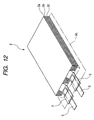
- Fig. 12 schematically shows the structure of a polymer lithium secondary battery 2.
- the polymer lithium secondary battery 2 is composed of a polymer electrolyte layer 2a formed by mixing a plasticizing material to a high polymer material, a positive electrode 2b and a negative electrode 2c laminated one another, and lead wire members 5 for tapping the power are connected with both the electrodes. Characteristics of the materials used in the electrolyte layer and other parts of the battery can change significantly depending on moisture in the atmosphere and other factors. In view of this, the parts other than the lead wire members 5 (which will be referred to as lead materials), namely, the electrolyte layer 2a, the positive electrode 2b and the negative electrode 2c are enclosed in an outer jacket member 4 that is not shown in the drawing.
- lead materials which will be referred to as lead materials
- the outer jacket member 4 encloses the electrolyte layer 2a and other parts in the position shown by the chain line in the drawing. It is necessary to draw the lead materials 5 out of the outer jacket. Accordingly, sealing materials 3 are inserted between the lead materials 5 and the outer jacket member 4 so that perfect sealing is achieved around the lead materials.
- lead materials have already been connected with a battery before it is enclosed in the outer jacket member, and the enclosing process and attaching of sealing materials to the lead materials are carried out at the same time.
- the lead materials connected to the positive and negative electrodes are caused to be in alignment with the laminate member including the electrolyte layer etc. and sealing materials are disposed on the upper and lower sides of the lead materials along the direction perpendicular to the direction in which the lead materials extend.
- the sealing materials and the lead materials are pressed together through the outer jacket member and heated.
- the sealing material made of a fusible material is fused to achieve fusion bonding and sealing between the outer jacket member and the lead materials.
- a laminate member including an electrolyte layer etc. is formed by using a sealing material on which a lead material has been attached in advance, and then it is subjected to an enclosing process.
- a lead material on which a sealing material is attached is formed in advance.
- Such a lead material is cut fitly, and lead materials attached with sealing materials after cut are used for producing a battery.
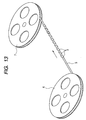
- Fig. 13 schematically shows such a process of attaching a sealing material to a lead material. As shown in Fig.
- the lead material 5 wound on a supply reel 6 is successively passed out along the direction indicated by an arrow, and pieces of the sealing material 3 are attached on the upper and the lower sides of the lead material at predetermined intervals.
- the lead material 5 on which the pieces of the sealing material 3 have been attached is rolled around a take-up reel 7.
- the sealing material is melted excessively, and there can occur the situation that it extends off the predetermined sealing portion to adhere to a machine tool used in the pressing process. In view of this, it is required to control the melting state of the sealing member reliably during the pressing process. Furthermore, in the aforementioned first case, the surfaces such as the side surface of the lead material that are perpendicular to the direction in which the pressing force is applied are not in contact with the sealing material at the time when the pressing and fusion bonding process is started. Accordingly, the possibility that the sealing is insufficient in these portions is considered to be higher than in the case of the second case, in which the sealing material and the lead material have been fusion-bonded in advance.
- this sealing process has an additional advantage of improvement in productivity in manufacturing batteries since fusion bonding of the lead material and the sealing material, which is the most time consuming process, has been finished in advance.
- the second case it is necessary to manufacture a lead material on which a sealing material has been attached in advance. In this case, it is considered that the fusion-bonded state of the sealing material and the lead material will not change basically in the process of fusion-bonding the outer jacket member and the sealing material that is effected later.
- a defect in the fusion-bonded state such as a gap for example
- methods of forming a sealing material on a lead material using a hot melt process or an extrusion lamination process have been employed.
- these methods involve an increase in complexity of equipments etc., and are not considered to be preferable from the viewpoint of manufacturing cost.
- the aforementioned batteries are used in small terminal devices such as cellular phones, they are required to not only be made small but also have desired shapes and designs in accordance with the terminal devices. Accordingly, in attaching sealing materials on a lead material, it is required that the attaching pitch thereof or other factors can be changed easily. However, in the aforementioned hot melt process etc., changing of the attaching pitch requires complicated and fine adjustment of the equipment used in carrying out the method. In commonly used apparatuses for simultaneously attaching a plurality of sealing materials on a lead material, operations that require complicated and fine adjustment, such as once dismounting sealing material holding portions and changing their mounting pitch, are required.
- the present invention has been made in view of the above-described problems and has as an object to provide a method of attaching a sealing material to a lead material in which the attaching pitch etc. can be easily changed while reliable attachment between the lead material and the sealing material is ensured, and an apparatus having a simple structure used for carrying out the method.
- a method for attaching a sealing material to a lead material by splitting the sealing material into pieces each having a predetermined length and fusion-bonding the pieces to predetermined positions on the lead material respectively comprising a step of holding the sealing material by means of a plurality of pressure contact tools, a step of cutting the sealing material thus held into the pieces each having a predetermined length using a plurality of cutting tools, a step of driving the plurality of pressure contact tools to transfer the pieces in such a way that adjacent pieces are opposed to each other with the lead material between to form pairs and the pairs are disposed on the lead material at regular intervals corresponding to the predetermined positions, and a step of attaching the sealing material pieces to the lead material by means of the plurality of pressure contact tools.
- the lead material be disposed away from the sealing material by a predetermined distance and parallel to it and that while the pieces are transferred through the predetermined distance, the pairs be formed and the regular intervals between the pairs are arranged. It is also preferred that while the pieces are transferred, the adjacent pieces form pairs, and thereafter a plurality of the pairs be transferred onto the lead material following substantially radially patterned paths. Furthermore, it is also preferred that during the transfer of the pieces, the adjacent pieces form the pairs and the pieces be transferred onto the lead with the intervals between the pairs being changed at constant ratios. Still further, it is preferred that adjustment of the intervals between the pairs be performed simultaneously with the transfer of the pairs onto the lead material.
- the lead material be heated through an area other than the predetermined positions on which the pieces are attached.
- the aforementioned method further include, in addition to the above-described steps, at least one of a step of pressurizing the lead material and the sealing materials attached on the lead material and simultaneously heating them to improve a re-pressure-contact condition, and a step of heating the lead material on which the sealing material has been attached and heating the attached sealing material to fuse the sealing material.
- a method for attaching a sealing material to a lead material by splitting the sealing material into pieces each having a predetermined length and fusion-bonding the pieces to predetermined positions on the lead material respectively, wherein in a process of attaching the pieces to predetermined positions on the lead material, the lead material is heated through an area other than the predetermined positions.
- the method further include, at least one of a process of pressurizing the lead material and the sealing materials attached on the lead material and simultaneously heating them to improve a re-pressure-contact condition and a process of heating the lead material on which the sealing material has been attached and heating the attached sealing material to fuse the sealing material.
- an apparatus for attaching a sealing material to a lead material by splitting the sealing material into pieces each having a predetermined length and fusion-bonding the pieces to predetermined positions on the lead material wherein a sealing material attaching portion of the apparatus comprises a lead material holding tool for holding the lead material at a predetermined position, a cutting unit for splitting the sealing material into the plurality of pieces, a plurality of first pressure contact tools capable of holding the pieces and arranged along the length direction of the sealing material so as to correspond to alternate pieces in the series of the pieces, a plurality of second pressure contact tools capable of holding the pieces and arranged along the length direction of the sealing material so as to correspond to alternate pieces in the series of the pieces that are not held by the first pressure contact tools, and a pressure contact tool movement direction regulation apparatus for making the first pressure contact tools and the second pressure contact tools to transfer the pieces to the predetermined position on the lead material, for making the first pressure contact tools and the second pressure contact tools that are adjacent to each other are
- the pressure contact tool movement direction regulation apparatus comprise first projections formed at end portions of the first pressure contact tools, first cam grooves in which the first projections are received, second projections formed at end portions of the second pressure contact tools and second cam grooves in which the second projections are received and that when the first cam grooves and the second cam grooves are opposed to each other and viewed from above, the first cam grooves and the second cam grooves be arranged alternately at their base points so as to correspond to center-to-center intervals of the pieces and aligned to each other at a position predetermined distance away from the base points.
- the pressure contact tool movement direction regulation apparatus comprise first projections formed at end portions of the first pressure contact tools, first cam grooves in which the first projections are received, second projections formed at end portions of the second pressure contact tools and second cam grooves in which the second projections are received and that the first cam grooves and the second cam grooves are opposed to each other and viewed from above, the first cam grooves and the second cam grooves be arranged alternately at their base points so as to correspond to center-to-center intervals of the pieces and aligned to each other at a position predetermined distance away from the base points, and further extending from the aligned position with the aligned state being maintained wherein ratios of intervals of the cam grooves are kept constant.
- a member on which the first cam grooves are formed and a member on which the second cam grooves are formed can be moved in synchronization with each other independently from the first and second pressure contact tools.
- the lead material holding tool comprise a heater block that hold the lead material by a portion other than the predetermined positions on which the pieces are attached to heat the lead material.
- the above-described apparatus further comprise at least one of a pressure contact unit for pressing and heating the lead material and the sealing material attached on the lead material and a heating unit for heating the lead material on which the sealing material has been attached and heating the attached sealing material to fuse the attached sealing material.
- an apparatus for attaching a sealing material to a lead material by splitting the sealing material into pieces each having a predetermined length and fusion-bonding the pieces to predetermined positions on the lead material wherein a sealing material attaching portion of the apparatus comprises a lead material holding tool for holding the lead material at a predetermined position, a cutting unit for splitting the sealing material into the plurality of pieces, a plurality of first pressure contact tools capable of holding the pieces for transferring the pieces to predetermined positions on the lead material and attaching the pieces actually on the lead material, and a plurality of second pressure contact tools capable of holding the pieces for transferring the pieces to predetermined positions on the lead material and attaching the pieces actually on the lead material, wherein the lead material holding tool comprises a heater block that holds the lead material by a portion other than the predetermined positions on which the pieces are attached to heat the lead material.
- the apparatus further comprise at least one of a pressure contact unit for pressing and heating the lead material and the sealing material attached on the lead material and a heating unit for heating the lead material on which the sealing material has been attached and heating the attached sealing material to fuse the attached sealing material.
- Fig. 1 schematically shows the structure of the apparatus according to the embodiment of the present invention as seen from the front.
- the attaching apparatus 1 is composed of a sealing material supply portion 10, a lead material supply portion 20, a material forwarding portion 30, an attaching portion 100, re-pressure-contact portion 40, an inspection portion 50 and a take-up portion 60 arranged in the mentioned order along the path through which a sealing material 3 and a lead material 5 are conveyed.
- the sealing material supply portion 10 of this apparatus is composed of a sealing material reel 11 on which the sealing material 3 is wound, a sealing material reel holding portion 12 that rotatably holds the reel 11, sealing material guide rollers 13, 15 that guide the sealing material taken out from the reel 11, a sealing material tension roller 14 that applies a constant load to the sealing material 3.
- the lead material supply portion 20 is composed of a lead material reel 21 on which the lead material is wound, a lead material reel holding portion 22 that rotatably holds the reel 21, lead material guide rollers 23, 25, 27 that guide the lead material 5 taken out from the reel 21, a flattening roller 24 that is adapted to flatten the lead material 5 and a lead material tension roller 26 that applies a constant load to the lead material 5.
- the material forwarding portion 30 is composed of a sealing material forwarding portion 31 and a lead material forwarding portion 35 arranged side by side along the direction perpendicular to the plane of the drawing sheet.
- the sealing material forwarding portion 31 includes a suction mechanism 32 for holding the end portion of the sealing material 3 by suction and a linear reciprocating mechanism, which is not shown in the drawings, for driving the suction mechanism 32 along the direction indicated by an arrow in the drawing.
- the lead material forwarding portion 35 includes a clamp mechanism 36 for pinching the lead material 5 and a linear reciprocating mechanism, which is not shown in the drawings, for driving the clamp mechanism 36 along the direction indicated by the arrow in the drawing.
- the sealing material 3 and the lead material 5 are delivered to a attaching portion 100, which will be described later, through the material forwarding portion 30.
- the sealing materials 3 formed into a predetermined size are attached on the lead material 5 at a predetermined pitch.
- the finished product 7 including the lead material etc. is transferred to the re-pressure-contact portion 40.
- the re-pressure-contact portion 40 includes a pressure contact unit 41, which is disposed above and below the finished product 7 under transferring, and a heating unit 42.
- Fig. 11A schematically shows the structure of the pressure contact unit 41 as seen from the front.
- the pressure contact unit 41 is composed of an upper plate 43 and a lower plate 44.
- the plates 43 and 44 can be biased toward each other by a pressurizing mechanism, which is not shown in the drawings, with the lead material between.
- the temperature of these plates 43, 44 is controlled by a temperature adjusting mechanism, which is not shown in the drawings, in such a way that the temperature is kept, for example, 20 to 30 degrees higher than the melting point of the sealing material 3.
- pressure is applied on pieces of the sealing material 3 attached on both sides of the lead material 5 again by the upper plate 43 and the lower plate 44 and heating is also effected.
- close attachment of the sealing material to, for example, the sides of the lead material 5 etc., which has not been sufficiently achieved by the attaching portion 100 is improved.
- Fig. 11B schematically shows the structure of the heating unit 42 as seen from the front.
- the heating unit is composed of an upper heating plate 46 and a lower heating plate 47. These plates 46 and 47 can be biased toward each other by a pressurizing mechanism, which is not shown in the drawings, with the lead material 5 between.
- the plates 46 and 47 have an upper recess 46a and a lower recess 47a respectively formed on the opposed surfaces. These recesses have a size large enough to accommodate pieces of the sealing material 3 attached on the lead material 5.
- the temperature of these plates 46, 47 is also controlled by a temperature control mechanism that is not shown in the drawings in a similar manner as in the pressure contact unit 41.
- the upper heating plate 46 and the lower heating plate 47 holds the lead material 5 between them at a position near the sealing material pieces to heat them to a predetermined temperature. Simultaneously, the sealing material pieces are indirectly heated by the heating plates 46, 47 through the space formed by the upper recess 46a and the lower recess 47a. By this process, the sealing material that has been brought into pressure contact with the lead material 5 again by the pressure contact unit 41 is fused, and a gap present between the sealing material and the lead material can be eliminated completely.
- the take-up portion 60 is composed of a finished product reel 61 on which the lead in the form of the finished product 7 on which the sealing material has been attached is wound, a finished product reel holding portion 62 that rotatably holds the reel 61, finished product guide roller 63, 65, 66 that guide the finished product 7 to be wound on the reel 61 and a finished product tension roller 64 that applies a constant load to the finished product 7.
- the sealing material 3 stored on the sealing material reel 11 is held by the suction mechanism 32 in the state in which its tension is kept constant by the sealing material tension roller 14, and the suction mechanism 32 is driven to move in the direction indicated by the arrow in this state.
- the sealing material 3 is delivered to the attaching portion 100.
- the lead material 5 stored on the lead material reel 21 is pinched by the clamp mechanism 36 in the state in which its tension is kept constant by the lead material tension roller 26, and the clamp mechanism 36 is driven to move in the direction indicated by the arrow in this state.
- the lead material 5 is delivered to the attaching portion 100.
- the sealing material 3 is cut to a predetermined length and attached on a predetermined position on the lead material 5.
- the lead material 5 on which the sealing material 3 has been attached, which constitutes the finished product 7 is transferred to the re-pressure-contact portion 40, in which it is pressed from the upper and lower sides of the lead material 5 to improve the attaching condition of the sealing material 3.
- the lead material etc. 7 after pressure contact is subject to inspection in terms of the presence/absence of the sealing material and the attaching condition etc. in the inspection portion 50 disposed downstream of the pressure contact portion 40.
- attaching portion 100 There are two types of attaching portions 100 which are used in accordance with application.
- the positions on the lead material 5 at which pieces of the sealing material are to be attached are fixed, while in the other type, the attaching positions can be changed.
- an arrangement in which the attaching positions are fixed will be specifically described as embodiment 1
- an arrangement in which the attaching position can be changed will be specifically described as embodiment 2.
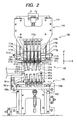
- Fig. 2 schematically shows an attaching portion 100 according to embodiment 1 as seen from the front.
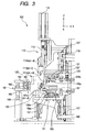
- Fig. 3 is a schematic side view thereof.
- Fig. 4 schematically shows the configuration of the components of this embodiment just before the sealing material 3 is cut.
- Fig. 5 schematically shows the configuration of the components of this embodiment just before the sealing material 3 is attached to the lead material 5.
- the attaching portion 100 is composed of a cutting unit 110, an upper pressure contact unit 120, a lower pressure contact unit 150, a heating unit 180.
- the heating unit 180 also functions as a holder for the lead material 5.
- the X axis is defined along a direction substantially parallel to the plane of the drawing sheet of Fig. 2
- the Z axis is defined along the direction parallel to the plane of the drawing sheet and perpendicular to the X axis
- the Y axis is defined along the direction perpendicular to the X axis and the Z axis (i.e. perpendicular to the plane of the drawing sheet).
- the cutting unit 110 is composed of a plurality of cutters 111a to 111j serving as cutting tools, cutter holders 112a to 112e that hold the cutters, a support base 113 on which the cutter holders are fixed and a cylinder 114 joined to the support base 113 to drive it along the Z axis direction.
- the cutter holder 112a to 112e extend along the Z axis and are arranged parallel to each other at regular intervals along the X axis direction.
- the cutters 111a to 111j are mounted on both sides of each of the cutter holders 112a to 112e in such a way that their edge portions are directed downward along the Z axis and that they are arranged at regular intervals along the X axis direction.
- the upper pressure contact unit 120 is composed of an upper pressure contact unit mount base 121, an upper base plate 123, upper Y axis direction guide rails 125a and 125b, an upper slide table 127, upper X axis direction guide rails 129a and 129b and upper pressure contact tools 131a to 131e.
- the lower pressure contact unit150 is substantially symmetrical to the upper pressure contact unit 120 with respect to an X-Y plane and composed of a lower pressure contact unit mount base 151, a lower base plate 153, lower Y axis direction guide rails 155a and 155b, a lower slide table 157, lower X axis direction guide rails 159a and 159b and lower pressure contact tools 161a to 161e.
- Each of the upper pressure contact unit 120 and the lower pressure contact unit 150 is adapted to be movable upward and downward along the Z axis direction.
- the upper pressure contact unit mount base 121 is equipped with a lever 135 for upwardly and downwardly moving the upper unit
- the lower pressure contact unit 150 is equipped with a lever for upwardly and downwardly moving the lower unit.
- the upper pressure contact unit 120 is slidably connected to an upper Z axis direction guide rail 137 extending along the Z axis direction
- the lower pressure contact unit 150 is slidably connected to a lower Z axis direction guide rail 167.
- the structure of the lower pressure contact unit 150 will be described with reference to Figs. 4 and 5, which are perspective view schematically show the cutting state of the sealing material in the cutting unit 110 and the attaching state of the sealing member 3 respectively.
- the lower Y axis direction guide rails 155a and 155b extending parallel to the Y axis are disposed on both sides of the base plate 153 and fixed on a surface 151a parallel to the X-Y plane formed on the lower pressure contact unit mount base 151.
- the lower slide table 157 is independent from the lower base plate 153 and mounted at its bottom in such a way that it can slide along the Y axis direction relative to the lower Y axis direction guide rails 155a and 155b.
- the lower X axis direction guide rails 159a and 159b extending parallel to the X axis direction are fixed on the top surface of the lower slide table 157.
- the lower pressure contact tools 161a to 161e are mounted at their bottoms in such a way that they can slide along the X axis direction relative to the lower X axis direction guide rails 159a and 159b.
- the lower pressure contact tools 161a to 161e extend along the Y axis direction and have, at their rear edge portions, lower projections 162a to 162e projecting downwardly in the Z axis direction.
- the lower projections 162a to 162e, the lower cam grooves 164a to 164e, upper projections 132a to 132e and upper cam grooves 164a to 164e constitute the pressure contact tool movement direction regulating apparatus.
- the lower pressure contact tools 161a to 161e have suction ports 163a to 163e on their upper surfaces facing toward the Z axis direction at their front end portions with respect to the Y axis direction. Pieces of the sealing material 3 cut off by the cutting unit 110 are separately sucked and held by these suction ports.
- the pressure contact unit 150 having the above-described structure, it is possible to regulate the drive direction of the pressure contact tools 161a to 161e in accordance with the lower cam grooves 164a to 164e upon driving the lower pressure contact tools 161a to 161e substantially along the Y axis direction.
- parallelism of the pressure contact tools is maintained by virtue of the function of the lower slide table 157 and the lower X axis direction guide rails 159a and 159b.
- the distances between the cam grooves 164a to 164e increases from the rear end to the front end, along the Y axis direction, of the lower base plate 153.
- the cam grooves 164a to 164e are formed in a radial manner, in a sense. Accordingly, when for example, the pressure contact tools 161a to 161e are driven frontward along the Y axis direction, each distance between the pressure contact tools gradually increases as the driving progresses. Even While the pressure contact tools 161a to 161e are driven following the cam grooves, parallelism of them is maintained and their distances are maintained to be equal to each other.
- pieces of the sealing material 3 can be attached at a predetermined interval by stopping the driving of the pressure contact tools at the time when the distance between the centers of the cam grooves becomes equal to the distance between the centers of the sealing materials to be attached on the lead material and carrying out the attaching process.
- the structure of the lower pressure contact unit 150 is substantially symmetrical to the upper pressure contact unit 120 with respect to an X-Y plane, and the lower pressure contact unit 150 has substantially the same components as those in the upper pressure contact unit 120.
- the upper projections 132, the upper cam grooves 134, the lower projections 162 and the lower cam grooves constitute, in combination, the pressure contact tool movement direction regulating apparatus in the present invention.
- the difference between these pressure contact units reside only in the portion relating to the cam grooves provided in them.
- Fig. 6 shows the configuration of the cam grooves formed on the lower base plate as viewed from above along the Z axis, movement paths of the projections in the lower pressure contact tools, and the positions at which the sealing material 3 is attached on the lead material 5.
- Each of the sealing material pieces 3a to 3j shown in this drawing is a sealing material 3 having been cut to a predetermined length by the cutting unit 110.
- the lower pressure contact tools 161a to 161e suck and hold the sealing material pieces 3b, 3d, 3f, 3h and 3j during and after cutting at the positions at which they are cut.
- Each pressure contact tool sucks and holds the corresponding sealing material piece.
- the lower projections 162a to 162e are disposed at the rear end portions (or the base points) of the lower cam grooves 164a to 164e.
- each pressure contact tool is driven to the position indicated by P2 in the drawing while holding a sealing material piece.
- the lower projection 162e for example, is driven along the lower cam groove 164e.
- the sealing material piece 3j held by the pressure contact tool 161e is positioned at just above the predetermined attaching position on the lead material 5, and an actual attaching process is carried out at this position.
- the pressure contact tools 131a to 131e in the upper pressure contact unit 120, the upper projections 132a to 132e and the upper cam grooves 134a to 134e are substantially symmetrical [to those in the lower pressure contact unit 150] with respect to the sealing material 3 as described before.
- the upper pressure contact unit is offset from the lower pressure contact unit in the X axis direction by a distance corresponding to the cut length of the sealing material so that the pressure contact tools 131a to 131e are opposed to the sealing material pieces 3a, 3c, 3e, 3g, 3i.
- the base points of the upper cam grooves and the base points of the lower cam grooves are offset in the X axis direction by a predetermined distance.
- the upper pressure contact tools and the lower pressure contact tools are disposed alternately, and all of the series of sealing material pieces are sucked and held by the suction end portions of the respective pressure contact tools.
- the upper cam grooves 134a to 134e are designed in such a way that when the upper projections 132a to 132e are positioned at the front end portions (or the attaching positions) of the corresponding upper cam grooves, the sealing material pieces 3a, 3c, 3e, 3g, 3i held by the respective pressure contact tools are opposed to the sealing material pieces 3b, 3d, 3f, 3h and 3j with the lead material 5 between.
- the upper cam grooves and lower cam grooves are formed in radial patterns respectively.
- the shape of the cam grooves is not limited to that in this embodiment, but they may have any shape so long as they satisfy the conditions that at the base points, the pressure contact tools correspond to the positions of the sealing materials as they are cut, and at the drive side end, the upper pressure contact tools and the lower pressure contact tools are paired and disposed at predetermined positions.
- the heating unit 180 is disposed in the attaching unit 100 at a position adjacent to the lead material held therein.
- the heating unit 180 is composed of an upper heater block 181, a lower heater block 185, an upper heater 182 and a lower heater 186 accommodated in these blocks to heat them, and a driving cylinder 189 that drives the blocks.
- the shape of the upper heater block 181 and the shape of the lower heater block 185 are symmetrical with respect to an X-Y plane in which the lead material 5 is disposed.
- These blocks 181 and 185 have recessed portions 183, 187 that can receive the front end portions, with respect to the Y axis direction, of the upper pressure contact tools 131a to 131e and the lower pressure contact tools 161a to 161e.
- areas on the lead material 5 other than the areas on which the sealing material is attached can be held between these blocks by driving the upper heater block 181 downwardly along the Z axis direction and driving the lower heater block 185 upwardly along the Z axis direction. Therefore, it is possible to heat the lead material to a predetermined temperature upon attaching the sealing material 3 by heating the blocks up to a predetermined temperature in advance.
- FIG. 7 schematically shows an attaching portion 100 according to embodiment 2 as seen from one side.
- Fig. 8 schematically shows the configuration of the components of this embodiment just before the sealing material 3 is attached to the lead material 5.
- the elements same as those in embodiment 1 are designated by the same reference signs, and only the elements having structures different from embodiment 1 will be described in detail.
- the structure other than the attaching portion 100 does not differ from embodiment 1, and the description thereof will be omitted.
- Embodiment 2 is different from embodiment 1 in whether the upper base plate 123 and the lower base plate 153 are movable with respect to the Y axis direction or not.
- the lower base plate 153 is supported by second lower Y axis direction guide rails 156a and 156b fixed on the lower pressure contact unit mount base 151 in such a way as to be slidable along the Y axis direction.
- the lower base plate 153 is connected with a lower base plate driving motor 154 at its rear end with respect to the Y axis direction, and driven by the motor 154 to move along the Y axis direction on the lower guide rails 1561 and 156b.
- first upper Y axis direction guide rails (not shown) and an upper base plate driving motor 124 are provided around it in a similar manner as the lower base plate 153.
- the lower base plate driving motor 154 is adapted to operate in synchronization with the upper base plate driving motor 124 to synchronize the drive positions with respect to the Y axis direction of the upper base plate 123 and the lower base plate 153.
- the intervals between adjacent pairs of sealing material pieces are set to a predetermined amount by driving the lower pressure contact tools 161a to 161e along the Y axis direction, for example, in such a way that the lower projections 162a to 162e are driven to the front end portions with respect to the Y axis direction of the lower cam grooves 164a to 164e. From this state, if only the lower base plate 154 is driven along the Y axis direction (in this case, in the frontward direction), the intervals between the lower cam grooves 164a to 164e decrease. Accordingly, the intervals between the lower pressure contact tools 161a to 161e are reduced by the driving of the lower base plate 154.
- the structure of the lower pressure contact unit 150 is substantially symmetrical to the upper pressure contact unit 120 with respect to an X-Y plane, and the upper pressure contact unit 120 has the substantially the same components. The difference between these units resides only in the portions related to the cam grooves.
- Figs. 9A and 9B show movement paths of the projections in the lower pressure contact tools, and the positions at which the sealing material 3 is attached on the lead material 5, in relative to the cam grooves formed on the lower base plate as seen from above with respect to the Z axis direction.
- Each of the sealing material pieces 3a to 3j shown in this drawing is a sealing material 3 having been cut to a predetermined length by the cutting unit 110.
- the lower pressure contact tools 161a to 161e suck and hold the sealing material pieces 3b, 3d, 3f, 3h and 3j during and after cutting at the positions at which they are cut.
- Each pressure contact tool sucks and holds the corresponding sealing material piece.
- the lower projections 162a to 162e are disposed at the rear end portions (or the base points) of the lower cam grooves 164a to 164e.
- the upper pressure contact tools only the upper cam groove 134e, in which the upper projection 134e related to the pressure contact tool 131e is received to regulate the pressure contact tool 131e is exemplarily illustrated.
- the distance between the upper cam groove 134e and the lower cam groove 164e decreases from the respective base points on X-Y planes shown in the drawings toward the Y direction and the cam grooves are aligned along the vertical direction at position Q.
- the suction end portion 133e of the upper pressure contact tool 131e and the suction end portion 163e of the lower pressure contact tool 161e are opposed to each other at position P3 while holding sealing material pieces 3j and 3i respectively.
- the upper cam groove 134e and the lower cam groove 164e form a pair to extend up to the attaching position (front end portion) while keeping aligned state along the vertical direction.
- the paired cam grooves are aligned along the vertical direction at the joining position Q, and extend to the front end portion, with respect to the Y axis direction, of the base plates 123 and 153 respectively while maintaining the aligned state.
- the sealing material pieces sucked and held by the respective pressure contact tools are paired at position P3 as sealing material piece pairs 3a and 3b, 3c and 3f, 3g and 3h, and 3i and 3j.
- each pressure contact tool is driven along the cam groove and stopped at position P2'.
- sealing material pieces 3a, 3c, 3e, 3g and 3i are opposed to sealing materials 3b, 3d, 3f, 3h and 3j with the lead material 5 between.
- position P2' of the pressure contact tools coincides with position P2 mentioned before.
- point P2' is discriminated here from point 2 mentioned before, since there is a possibility that the pressure control tools may be shifted along the X axis direction as will be described later.
- the sealing material piece 3j (3i), the lower cam groove 164e, the lower projection 162e and the lower base plate 153 in this state are illustrated in the drawing by broken lines. From this state, only the base plate 153 is driven to move frontward (in the direction indicated by arrow R in the drawing) with respect to the Y axis direction.
- the lower projection 162e slides backward with respect to the Y axis direction relative to the corresponding cam groove. Since the lower cam grooves 164a to 164e are arranged in a substantially radial pattern as described before, the intervals between the lower projections 162a to 162e decrease with this relative sliding movement, and intervals of the lower pressure contact tools and the sealing material pieces held by them are also reduced.
- the upper base plate 123 is also driven to move in synchronization with the driving of the lower base plate 153, whereby the intervals of the paired sealing material pieces decrease while maintaining the opposed state.
- the intervals of the sealing material pieces to be attached on the lead material can be controlled as desired by controlling the drive amount of the base plates.
- the radial pattern mentioned here refers to the pattern in which the intervals of plurality of grooves starting from a plurality of base points arranged on a line increase as the grooves extend while maintaining constant ratios between the intervals of the grooves on lines parallel to said line.
- a description of embodiment 2 has been made to the effect that driving of the base plates and changing of the intervals of the pressure contact tools are effected after the pressure contact tools have been stopped at a predetermined position substantially at the front end of the corresponding cam grooves.
- driving of the pressure contact tools and driving of the base plates are typically performed substantially simultaneously, and it should be understood that what is described above has been presented for illustrative purpose. Therefore, the order of driving of the pressure contact tools and driving of the base plates is not limited to that in the description of this embodiment.
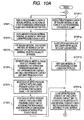
- step 1 the suction mechanism 32 in the sealing material forwarding portion 30 sucks the end portion of the sealing material 3, and the suction unit 32 is moved to a predetermined position in the attaching unit 100 to feed a certain length of the sealing material 3 into the unit 100.
- step 11 the clamp mechanism 36 of the lead material forwarding portion 35 clamps the lead material 5, and the clamp mechanism 36 is moved to a predetermined position in the attaching unit 100 to feed a predetermined length of the lead material 5 into the unit 100.
- the upper pressure contact unit 120 is moved downward and the lower pressure contact unit 150 are moved upward simultaneously in step 2, and the sealing material 3 is sucked and held by the upper suction ports 133a to 133e and the lower suction ports 163a to 163e.
- the cutters 111a to 111j of the cutting unit 100 is moved down, so that the sealing material 3 is cut to a predetermined length.
- auxiliary ports 166 provided between the lower pressure contact tools 161a to 161e are illustrated in Fig. 4. These ports are used for sucking and holding the sealing material 3 in cooperation with the upper pressure contact tools 131a to 131e and lower pressure contact tools 161a to 161e after the feeding of a certain length of the sealing material 3 is completed to retain the sealing material 3 stably before and after cutting. After the sealing material 3 is cut, suction of the sealing material by the suction mechanism 32 and the suction ports 166 is disabled, and the upper pressure contact tools 131a to 131e and the lower pressure contact tools 161a to 161e are moved downward and upward respectively to separate the sealing materials 3 after the cutting.
- step 12 the lead material 5 is held between the upper heater block 181 and the lower heater block 185 that have been heated to a predetermined temperature.
- heating of the lead material 5 is started.
- the held state is maintained continuously to perform heating of the lead material in subsequent step 13, and this state is kept until attaching of the sealing material is completed.
- next step 5 the upper pressure contact tools 131a to 131e and lower pressure contact tools 161a to 161e are driven to move front ward with respect to the Y axis direction following the upper and lower cam grooves 134a to 134e and 164a to 164e. As described before, by this movement, sealing materials that have been juxtaposed side by side are opposed to each other along the vertical direction. When the sealing materials held by the pressure contact tools are carried to predetermined positions on the lead material 5, the interval between paired sealing materials (sealing material pieces) will be a predetermined interval.
- step 6 is performed as such a process.
- step 6 after each of the projections has slid to a predetermined position in the front end portion with respect to the Y axis direction of the corresponding groove and the intervals of adjacent pairs of pressure contact tools have become predetermined intervals, the base plates 123 and 153 on which the cam grooves are provided are driven along the Y axis direction by the driving motors annexed to the respective base plates.
- step 14 the upper pressure contact tools 131a to 131e are moved down and the lower pressure contact tools 161a to 161e are moved up, and the sealing material pieces are attached on the upper and lower surfaces of the lead material.
- step 6 is performed after step 5, the order of these steps is not limited to this, for example, the process of these two steps may actually be performed simultaneously.
- the sealing material pieces fuse at their surface in contact with the lead material 5 by the heat of the lead material 5 itself. In addition, they are pressed from above and below by the pressure contact tools, and sealing material pieces are made integral. After the sealing material pieces are fusion bonded, the pressure contact tools are moved away from the sealing material pieces and the heater blocks are moved away from the lead material in step 15 and step 16. After that, the upper pressure contact unit 120 and the lower pressure contact unit 150 are retracted to the position for sucking the sealing material 3 to prepare for the next process.
- the lead material on which the sealing material pieces have been fusion-bonded is transferred to the re-pressure-contact portion 40, in which attachment between the sealing material pieces 3 and the lead material 5 is improved.
- attachment of the sealing material pieces 3 and the lead material 5 is firstly improved by the pressing unit 41.
- the sealing material pieces 3 and the lead material 5 are held together by the upper plate 43 and the lower plate 44 that are kept to a temperature higher than the melting point of the sealing material with a pressing force stronger than in the pressing force applied in the attaching portion 100 to improve the attachment.
- the lead material 5 is directly heated, and, in addition, the sealing material pieces 3 and the lead material 5 are subjected to indirect heating through the air. With these heating, sealing material is fused, so that gaps that may be present between the sealing material pieces and the lead material 5 can be eliminated.
- the upper and lower sealing pieces are fused together and the sealing material 5 is circumferentially covered with the sealing material 3 thus fusion-bonded.
- a new sealing material 3 and a lead material 5 on which the sealing material has not been attached are fed to the attaching portion 100, and the next attaching process is started.
- the sealing material and the lead material are provided in the state wound around respectively dedicated reels, and the lead material on which the sealing material has been attached is also taken up on a dedicated reel.
- the present invention is not limited to such a structure.
- the present invention may be applied in connection with supply of various shapes of sealing materials, formation and discharge of various shapes of lead materials on which sealing material have been attached.
- the sealing material or the lead material may be provided in the form of a long material having a specific length, and the lead on which the sealing material has been attached may be cut to a predetermined length.
- lead material made of different materials and sealing materials made of different materials may be arranged in parallel to use them one after another.
- the number of the pressure contact tools and other factors be changed appropriately in accordance with productivity required in actual processes.
- the lead material and the sealing material are held by clamping and suction respectively, no particular limitation is placed on the mode of holding, and they may be held by a different method such as attraction of the lead material with a magnetic force.
- the pressure contact tool movement direction regulation apparatus is composed of projections and cam grooves, this apparatus is not limited to the structure of this embodiment but it may have any structure in which the intervals between the respective pressure contact tools are kept constant and the interval can be changed.
- the cam grooves are formed in a radial pattern, the pattern is not simply radial.
- the pattern may include an area in which the cam grooves extend parallel, or include an area in which the cam grooves are represented by curves in an X-Y plane.
- the present invention is not limited to the described case.
- adjacent sealing material pieces forms pairs along the vertical direction, and there are gaps as large as one sealing material piece are formed between adjacent pairs. Therefore, in the case that the attachment intervals of the sealing material pieces on the lead material are smaller than these gaps, the distance between adjacent grooves may be decrease as they extend away from the base points.
- the heating of the heating blocks in the heating unit may be effected by means of various heat media such as hot water for example.
- the shape of the heater block is not limited to the comb tooth shape having a recess as shown in connection with the embodiments, but it is desirable that the shape be changed appropriately in accordance with the attaching intervals of the sealing material or other factors.
- a cooling unit having a structure similar to the heating unit may be provided in the re-pressure-contact unit to facilitate solidification of the fused sealing material positively.
- the lead material have a tape-like shape and its top and bottom surfaces are oriented to the vertical direction
- the present invention is not limited to the embodiments.
- the top and bottom surfaces of the lead material may be oriented horizontally
- the lead material may be a wire
- the transfer direction of the lead material etc. may be vertical.
- components such as the pressure contact tools, projections and cam grooves are discriminated by the adjectives "upper” and “lower”, it is desirable, to speak properly, that they should be discriminated by the adjectives "first” and “second”.
- the cam grooves are arranged in a radial manner, it is preferred that the arrangement pattern be modified appropriately depending on the attaching intervals of the sealing material and the required stroke along the Y axis direction, of the pressure contact tools etc..
- the sealing material can be attached to the lead material in the state completely fused to the lead material circumferentially. Accordingly, when jacketing of a battery is performed in the next process step using that lead material, a jacketing state with stable sealing performance can be achieved without excessive fusion of the sealing material.
- temperature control optimal for the attaching process can be achieved by setting the heat capacity of the heating unit, the time through which the lead material is held by the unit, the timing of starting the holding of the lead material or the timing of stopping the holding of the lead material.
Landscapes
- Chemical & Material Sciences (AREA)
- Chemical Kinetics & Catalysis (AREA)
- Electrochemistry (AREA)
- General Chemical & Material Sciences (AREA)
- Engineering & Computer Science (AREA)
- Manufacturing & Machinery (AREA)
- Materials Engineering (AREA)
- Connection Of Batteries Or Terminals (AREA)
- Sealing Battery Cases Or Jackets (AREA)
- Secondary Cells (AREA)
- Lining Or Joining Of Plastics Or The Like (AREA)
- Basic Packing Technique (AREA)
Abstract
Description
- The present invention relates to a lead wire used in a battery having an outer jacket made of aluminum etc. such as a polymer lithium battery, a lithium ion battery and an advanced lithium ion battery. More particularly, the present invention relates to a method of attaching a sealing material attached to the lead wire in order to provide a seal between lead wire and a laminate outer jacket, to the lead wire (material) and an attaching apparatus therefor.
- In recent years, with popularization of small and lightweight mobile terminal devices such as cellular telephones, batteries for supplying electric power for driving these mobile terminal devices have been developed. Such batteries are required to be small in size, have durability against many times of recharging operations over a significantly long term and show stable output characteristics. Lithium ion batteries such as polymer lithium secondary batteries having a polymeric electrolyte layer are widely used as batteries that meet the above requirements.
- Fig. 12 schematically shows the structure of a polymer lithium
secondary battery 2. The polymer lithiumsecondary battery 2 is composed of apolymer electrolyte layer 2a formed by mixing a plasticizing material to a high polymer material, apositive electrode 2b and anegative electrode 2c laminated one another, andlead wire members 5 for tapping the power are connected with both the electrodes. Characteristics of the materials used in the electrolyte layer and other parts of the battery can change significantly depending on moisture in the atmosphere and other factors. In view of this, the parts other than the lead wire members 5 (which will be referred to as lead materials), namely, theelectrolyte layer 2a, thepositive electrode 2b and thenegative electrode 2c are enclosed in anouter jacket member 4 that is not shown in the drawing. Theouter jacket member 4 encloses theelectrolyte layer 2a and other parts in the position shown by the chain line in the drawing. It is necessary to draw thelead materials 5 out of the outer jacket. Accordingly, sealingmaterials 3 are inserted between thelead materials 5 and theouter jacket member 4 so that perfect sealing is achieved around the lead materials. - There are two methods, which will be described in the following, commonly used for inserting the sealing materials.
- First, in some cases, lead materials have already been connected with a battery before it is enclosed in the outer jacket member, and the enclosing process and attaching of sealing materials to the lead materials are carried out at the same time. In this case, the lead materials connected to the positive and negative electrodes are caused to be in alignment with the laminate member including the electrolyte layer etc. and sealing materials are disposed on the upper and lower sides of the lead materials along the direction perpendicular to the direction in which the lead materials extend. After that, the sealing materials and the lead materials are pressed together through the outer jacket member and heated. Thus, the sealing material made of a fusible material is fused to achieve fusion bonding and sealing between the outer jacket member and the lead materials.
- Secondly, in other cases, a laminate member including an electrolyte layer etc. is formed by using a sealing material on which a lead material has been attached in advance, and then it is subjected to an enclosing process. In this case, as will be seen in an example disclosed in Japanese Patent Application Laid-Open NO. 11-312514, a lead material on which a sealing material is attached is formed in advance. Such a lead material is cut fitly, and lead materials attached with sealing materials after cut are used for producing a battery. In this connection, in fusion bonding the sealing material and the outer jacket member, these members are pressed and heated through the outer jacket member. Fig. 13 schematically shows such a process of attaching a sealing material to a lead material. As shown in Fig. 13, the
lead material 5 wound on asupply reel 6 is successively passed out along the direction indicated by an arrow, and pieces of the sealingmaterial 3 are attached on the upper and the lower sides of the lead material at predetermined intervals. Thelead material 5 on which the pieces of the sealingmaterial 3 have been attached is rolled around a take-up reel 7. - In order to seal between the sealing material and the lead material, it is necessary to heat the surface of the lead material that is in contact with the sealing material to a temperature higher than the fusing temperature of the sealing material. However, in the aforementioned first method, since the heating is effected through the outer jacket member, heat-escape occurs through the outer jacket member. In both the cases, the lead material is usually made of a metal having a high heat conductivity, and heat-escape through the lead material also occurs. For this reason, in the case that the heating state is not known sufficiently, fusion of the sealing material can be insufficient and reliable sealing cannot be achieved in some cases.
- On the other hand, if heating is effected for a long time more than the time required for heating the lead material sufficiently, the sealing material is melted excessively, and there can occur the situation that it extends off the predetermined sealing portion to adhere to a machine tool used in the pressing process. In view of this, it is required to control the melting state of the sealing member reliably during the pressing process. Furthermore, in the aforementioned first case, the surfaces such as the side surface of the lead material that are perpendicular to the direction in which the pressing force is applied are not in contact with the sealing material at the time when the pressing and fusion bonding process is started. Accordingly, the possibility that the sealing is insufficient in these portions is considered to be higher than in the case of the second case, in which the sealing material and the lead material have been fusion-bonded in advance.
- In view of the above circumstances, if more reliable sealing performance is to be achieved, it is considered to be more preferable to employ the sealing process according to the above-described second case. In addition, this sealing process has an additional advantage of improvement in productivity in manufacturing batteries since fusion bonding of the lead material and the sealing material, which is the most time consuming process, has been finished in advance. However, in the second case, it is necessary to manufacture a lead material on which a sealing material has been attached in advance. In this case, it is considered that the fusion-bonded state of the sealing material and the lead material will not change basically in the process of fusion-bonding the outer jacket member and the sealing material that is effected later.
- Accordingly, if a defect in the fusion-bonded state, such as a gap for example, is present in that process, it is difficult to mend it. Therefore, it is required that complete contact (fusion bonding) of the sealing material and the lead material be established when these materials are attached. For this purpose, methods of forming a sealing material on a lead material using a hot melt process or an extrusion lamination process have been employed. However, in the case that the sealing materials are to be formed on a plurality of independent small areas on the lead material, these methods involve an increase in complexity of equipments etc., and are not considered to be preferable from the viewpoint of manufacturing cost.
- Furthermore, in the conventional process of cutting a tape-like sealing member and attaching it on a predetermined position on a lead material, the lead material is heated from the circumference of the sealing material. Accordingly, it is difficult to control the temperature of the lead material, and the attachment between the lead material and the sealing material cannot be controlled reliably, in some cases. In addition, in this case, surplus sealing material is cut and discarded. Thus, reduction of the discarded portion has been demanded from the standpoint of manufacturing cost saving.
- Furthermore, since the aforementioned batteries are used in small terminal devices such as cellular phones, they are required to not only be made small but also have desired shapes and designs in accordance with the terminal devices. Accordingly, in attaching sealing materials on a lead material, it is required that the attaching pitch thereof or other factors can be changed easily. However, in the aforementioned hot melt process etc., changing of the attaching pitch requires complicated and fine adjustment of the equipment used in carrying out the method. In commonly used apparatuses for simultaneously attaching a plurality of sealing materials on a lead material, operations that require complicated and fine adjustment, such as once dismounting sealing material holding portions and changing their mounting pitch, are required.
- The present invention has been made in view of the above-described problems and has as an object to provide a method of attaching a sealing material to a lead material in which the attaching pitch etc. can be easily changed while reliable attachment between the lead material and the sealing material is ensured, and an apparatus having a simple structure used for carrying out the method.
- To achieve the above object, according to the present invention, there is provided a method for attaching a sealing material to a lead material by splitting the sealing material into pieces each having a predetermined length and fusion-bonding the pieces to predetermined positions on the lead material respectively, comprising a step of holding the sealing material by means of a plurality of pressure contact tools, a step of cutting the sealing material thus held into the pieces each having a predetermined length using a plurality of cutting tools, a step of driving the plurality of pressure contact tools to transfer the pieces in such a way that adjacent pieces are opposed to each other with the lead material between to form pairs and the pairs are disposed on the lead material at regular intervals corresponding to the predetermined positions, and a step of attaching the sealing material pieces to the lead material by means of the plurality of pressure contact tools.
- In the above-described method it is preferred that the lead material be disposed away from the sealing material by a predetermined distance and parallel to it and that while the pieces are transferred through the predetermined distance, the pairs be formed and the regular intervals between the pairs are arranged. It is also preferred that while the pieces are transferred, the adjacent pieces form pairs, and thereafter a plurality of the pairs be transferred onto the lead material following substantially radially patterned paths. Furthermore, it is also preferred that during the transfer of the pieces, the adjacent pieces form the pairs and the pieces be transferred onto the lead with the intervals between the pairs being changed at constant ratios. Still further, it is preferred that adjustment of the intervals between the pairs be performed simultaneously with the transfer of the pairs onto the lead material.
- Furthermore, it is preferred that in the step of attaching the pieces to the lead material, the lead material be heated through an area other than the predetermined positions on which the pieces are attached. Furthermore it is preferred that the aforementioned method further include, in addition to the above-described steps, at least one of a step of pressurizing the lead material and the sealing materials attached on the lead material and simultaneously heating them to improve a re-pressure-contact condition, and a step of heating the lead material on which the sealing material has been attached and heating the attached sealing material to fuse the sealing material.
- To achieve the aforementioned object, according to the invention, there is provided a method for attaching a sealing material to a lead material by splitting the sealing material into pieces each having a predetermined length and fusion-bonding the pieces to predetermined positions on the lead material respectively, wherein in a process of attaching the pieces to predetermined positions on the lead material, the lead material is heated through an area other than the predetermined positions.
- In the above-described method, it is preferred that the method further include, at least one of a process of pressurizing the lead material and the sealing materials attached on the lead material and simultaneously heating them to improve a re-pressure-contact condition and a process of heating the lead material on which the sealing material has been attached and heating the attached sealing material to fuse the sealing material.
- Furthermore, to achieve the aforementioned object, according to the present invention there is provided an apparatus for attaching a sealing material to a lead material by splitting the sealing material into pieces each having a predetermined length and fusion-bonding the pieces to predetermined positions on the lead material, wherein a sealing material attaching portion of the apparatus comprises a lead material holding tool for holding the lead material at a predetermined position, a cutting unit for splitting the sealing material into the plurality of pieces, a plurality of first pressure contact tools capable of holding the pieces and arranged along the length direction of the sealing material so as to correspond to alternate pieces in the series of the pieces, a plurality of second pressure contact tools capable of holding the pieces and arranged along the length direction of the sealing material so as to correspond to alternate pieces in the series of the pieces that are not held by the first pressure contact tools, and a pressure contact tool movement direction regulation apparatus for making the first pressure contact tools and the second pressure contact tools to transfer the pieces to the predetermined position on the lead material, for making the first pressure contact tools and the second pressure contact tools that are adjacent to each other are opposed with their positions that hold the pieces facing to each other to form pairs, and for changing intervals of the plurality of pairs of the first pressure contact tools and second pressure contact tools thus formed.
- In the above-described apparatus, it is preferred that the pressure contact tool movement direction regulation apparatus comprise first projections formed at end portions of the first pressure contact tools, first cam grooves in which the first projections are received, second projections formed at end portions of the second pressure contact tools and second cam grooves in which the second projections are received and that when the first cam grooves and the second cam grooves are opposed to each other and viewed from above, the first cam grooves and the second cam grooves be arranged alternately at their base points so as to correspond to center-to-center intervals of the pieces and aligned to each other at a position predetermined distance away from the base points. Furthermore, it is preferred that the pressure contact tool movement direction regulation apparatus comprise first projections formed at end portions of the first pressure contact tools, first cam grooves in which the first projections are received, second projections formed at end portions of the second pressure contact tools and second cam grooves in which the second projections are received and that the first cam grooves and the second cam grooves are opposed to each other and viewed from above, the first cam grooves and the second cam grooves be arranged alternately at their base points so as to correspond to center-to-center intervals of the pieces and aligned to each other at a position predetermined distance away from the base points, and further extending from the aligned position with the aligned state being maintained wherein ratios of intervals of the cam grooves are kept constant.
- In the above-descried apparatus, it is preferred that a member on which the first cam grooves are formed and a member on which the second cam grooves are formed can be moved in synchronization with each other independently from the first and second pressure contact tools. Furthermore, it is preferred that the lead material holding tool comprise a heater block that hold the lead material by a portion other than the predetermined positions on which the pieces are attached to heat the lead material. Still further, it is preferred that the above-described apparatus further comprise at least one of a pressure contact unit for pressing and heating the lead material and the sealing material attached on the lead material and a heating unit for heating the lead material on which the sealing material has been attached and heating the attached sealing material to fuse the attached sealing material.
- Furthermore, to achieve the aforementioned object, according to the present invention there is provided an apparatus for attaching a sealing material to a lead material by splitting the sealing material into pieces each having a predetermined length and fusion-bonding the pieces to predetermined positions on the lead material, wherein a sealing material attaching portion of the apparatus comprises a lead material holding tool for holding the lead material at a predetermined position, a cutting unit for splitting the sealing material into the plurality of pieces, a plurality of first pressure contact tools capable of holding the pieces for transferring the pieces to predetermined positions on the lead material and attaching the pieces actually on the lead material, and a plurality of second pressure contact tools capable of holding the pieces for transferring the pieces to predetermined positions on the lead material and attaching the pieces actually on the lead material, wherein the lead material holding tool comprises a heater block that holds the lead material by a portion other than the predetermined positions on which the pieces are attached to heat the lead material.
- In the above-described apparatus, it is preferred that the apparatus further comprise at least one of a pressure contact unit for pressing and heating the lead material and the sealing material attached on the lead material and a heating unit for heating the lead material on which the sealing material has been attached and heating the attached sealing material to fuse the attached sealing material.
-
- Fig. 1 schematically shows the overall structure of a sealing material attaching apparatus according to an embodiment of the present invention as seen from the front.
- Fig. 2 schematically shows the structure of an attaching portion according to a first embodiment of the present invention as seen from the front.
- Fig. 3 schematically shows the attaching portion according to the first embodiment of the present invention as seen from a side.
- Fig. 4 schematically shows the configuration
components of a
cutting unit 110 in the state for cutting a sealingmaterial 3. - Fig. 5 schematically shows the configuration of
the components of the
cutting unit 110 in the state for attaching the sealingmaterial 3 according to the first embodiment. - Fig. 6 shows the configuration of cam grooves in the first embodiment for illustrating the shape of the cam grooves formed on a upper base plate and a lower base plate.
- Fig. 7 schematically shows an attaching portion according to a second embodiment of the present invention as seen from a side.
- Fig. 8 is a perspective view schematically
showing the configuration of components of a cutting
unit according to the second embodiment in the state
for attaching the sealing
material 3. - Fig. 9A shows the configuration of cam grooves in the second embodiment for illustrating the shape of the cam grooves formed on a upper base plate and a lower base plate.
- Fig. 9B shows the configuration of the cam grooves in the second embodiment for illustrating the shape of the cam grooves formed on a upper base plate and a lower base plate.
- Fig. 10A and 10B are flow charts of a process for attaching a sealing material to a lead material according to the present invention.
- Fig. 11A schematically shows a pressure contact unit according to the present invention as seen from the front.
- Fig. 11B schematically shows a heating unit according to the present invention as seen from the front.
- Fig. 12 schematically shows the structure of a polymer lithium secondary battery.
- Fig. 13 schematically shows a process of attaching sealing materials to a lead material.
-
- In the following, a sealing material attaching apparatus according to an embodiment of the present invention will be described with reference to the drawings. Fig. 1 schematically shows the structure of the apparatus according to the embodiment of the present invention as seen from the front. The attaching
apparatus 1 is composed of a sealingmaterial supply portion 10, a leadmaterial supply portion 20, amaterial forwarding portion 30, an attachingportion 100, re-pressure-contact portion 40, aninspection portion 50 and a take-upportion 60 arranged in the mentioned order along the path through which a sealingmaterial 3 and alead material 5 are conveyed. - The sealing
material supply portion 10 of this apparatus is composed of a sealingmaterial reel 11 on which the sealingmaterial 3 is wound, a sealing materialreel holding portion 12 that rotatably holds thereel 11, sealingmaterial guide rollers reel 11, a sealingmaterial tension roller 14 that applies a constant load to the sealingmaterial 3. The leadmaterial supply portion 20 is composed of alead material reel 21 on which the lead material is wound, a lead materialreel holding portion 22 that rotatably holds thereel 21, leadmaterial guide rollers lead material 5 taken out from thereel 21, a flatteningroller 24 that is adapted to flatten thelead material 5 and a leadmaterial tension roller 26 that applies a constant load to thelead material 5. - The
material forwarding portion 30 is composed of a sealingmaterial forwarding portion 31 and a leadmaterial forwarding portion 35 arranged side by side along the direction perpendicular to the plane of the drawing sheet. The sealingmaterial forwarding portion 31 includes asuction mechanism 32 for holding the end portion of the sealingmaterial 3 by suction and a linear reciprocating mechanism, which is not shown in the drawings, for driving thesuction mechanism 32 along the direction indicated by an arrow in the drawing. The leadmaterial forwarding portion 35 includes aclamp mechanism 36 for pinching thelead material 5 and a linear reciprocating mechanism, which is not shown in the drawings, for driving theclamp mechanism 36 along the direction indicated by the arrow in the drawing. - The sealing
material 3 and thelead material 5 are delivered to a attachingportion 100, which will be described later, through thematerial forwarding portion 30. The sealingmaterials 3 formed into a predetermined size are attached on thelead material 5 at a predetermined pitch. Then, thefinished product 7 including the lead material etc. is transferred to the re-pressure-contact portion 40. The re-pressure-contact portion 40 includes apressure contact unit 41, which is disposed above and below thefinished product 7 under transferring, and aheating unit 42. - Fig. 11A schematically shows the structure of the
pressure contact unit 41 as seen from the front. Thepressure contact unit 41 is composed of anupper plate 43 and alower plate 44. Theplates plates material 3. In thepressure contact unit 41, pressure is applied on pieces of the sealingmaterial 3 attached on both sides of thelead material 5 again by theupper plate 43 and thelower plate 44 and heating is also effected. Thus, close attachment of the sealing material to, for example, the sides of thelead material 5 etc., which has not been sufficiently achieved by the attachingportion 100, is improved. - Fig. 11B schematically shows the structure of the
heating unit 42 as seen from the front. The heating unit is composed of anupper heating plate 46 and alower heating plate 47. Theseplates lead material 5 between. Theplates upper recess 46a and alower recess 47a respectively formed on the opposed surfaces. These recesses have a size large enough to accommodate pieces of the sealingmaterial 3 attached on thelead material 5. The temperature of theseplates pressure contact unit 41. - The
upper heating plate 46 and thelower heating plate 47 holds thelead material 5 between them at a position near the sealing material pieces to heat them to a predetermined temperature. Simultaneously, the sealing material pieces are indirectly heated by theheating plates upper recess 46a and thelower recess 47a. By this process, the sealing material that has been brought into pressure contact with thelead material 5 again by thepressure contact unit 41 is fused, and a gap present between the sealing material and the lead material can be eliminated completely. - In the
inspection portion 50, there is provided animage pickup apparatus 51. An image of the sealingmaterial 3 attached on thelead material 5 is obtained by this image pickup apparatus, and the presence/absence of the sealingmaterial 3 and its attaching condition etc. are detected based on the image. The take-upportion 60 is composed of afinished product reel 61 on which the lead in the form of thefinished product 7 on which the sealing material has been attached is wound, a finished productreel holding portion 62 that rotatably holds thereel 61, finishedproduct guide roller finished product 7 to be wound on thereel 61 and a finishedproduct tension roller 64 that applies a constant load to thefinished product 7. - The sealing
material 3 stored on the sealingmaterial reel 11 is held by thesuction mechanism 32 in the state in which its tension is kept constant by the sealingmaterial tension roller 14, and thesuction mechanism 32 is driven to move in the direction indicated by the arrow in this state. Thus, the sealingmaterial 3 is delivered to the attachingportion 100. Thelead material 5 stored on thelead material reel 21 is pinched by theclamp mechanism 36 in the state in which its tension is kept constant by the leadmaterial tension roller 26, and theclamp mechanism 36 is driven to move in the direction indicated by the arrow in this state. Thus, thelead material 5 is delivered to the attachingportion 100. - In the attaching
portion 100, which will be described later, the sealingmaterial 3 is cut to a predetermined length and attached on a predetermined position on thelead material 5. Thelead material 5 on which the sealingmaterial 3 has been attached, which constitutes thefinished product 7, is transferred to the re-pressure-contact portion 40, in which it is pressed from the upper and lower sides of thelead material 5 to improve the attaching condition of the sealingmaterial 3. The lead material etc. 7 after pressure contact is subject to inspection in terms of the presence/absence of the sealing material and the attaching condition etc. in theinspection portion 50 disposed downstream of thepressure contact portion 40. The lead material etc. 7 after inspection is transferred to the take-upportion 60 and wound on thereel 61 after passing through theguide rollers product tension roller 64. Through the above-described process, thefinished product 7, or the lead material on which the sealing material has been attached is obtained. - Next, the attaching
portion 100 according to the present invention will be described in detail. There are two types of attachingportions 100 which are used in accordance with application. In one type, the positions on thelead material 5 at which pieces of the sealing material are to be attached are fixed, while in the other type, the attaching positions can be changed. In the following, an arrangement in which the attaching positions are fixed will be specifically described asembodiment 1, and an arrangement in which the attaching position can be changed will be specifically described asembodiment 2. - Fig. 2 schematically shows an attaching
portion 100 according toembodiment 1 as seen from the front. Fig. 3 is a schematic side view thereof. Fig. 4 schematically shows the configuration of the components of this embodiment just before the sealingmaterial 3 is cut. Fig. 5 schematically shows the configuration of the components of this embodiment just before the sealingmaterial 3 is attached to thelead material 5. The attachingportion 100 is composed of acutting unit 110, an upperpressure contact unit 120, a lowerpressure contact unit 150, aheating unit 180. Theheating unit 180 also functions as a holder for thelead material 5. - In order to facilitate descriptions of the driving direction of each component, the X axis is defined along a direction substantially parallel to the plane of the drawing sheet of Fig. 2, the Z axis is defined along the direction parallel to the plane of the drawing sheet and perpendicular to the X axis, and the Y axis is defined along the direction perpendicular to the X axis and the Z axis (i.e. perpendicular to the plane of the drawing sheet). These definitions apply to not only the first embodiment but also to the second embodiment that will be described later.
- The
cutting unit 110 is composed of a plurality ofcutters 111a to 111j serving as cutting tools,cutter holders 112a to 112e that hold the cutters, asupport base 113 on which the cutter holders are fixed and acylinder 114 joined to thesupport base 113 to drive it along the Z axis direction. Thecutter holder 112a to 112e extend along the Z axis and are arranged parallel to each other at regular intervals along the X axis direction. Thecutters 111a to 111j are mounted on both sides of each of thecutter holders 112a to 112e in such a way that their edge portions are directed downward along the Z axis and that they are arranged at regular intervals along the X axis direction. - The upper
pressure contact unit 120 is composed of an upper pressure contactunit mount base 121, anupper base plate 123, upper Y axisdirection guide rails direction guide rails pressure contact tools 131a to 131e. The lower pressure contact unit150 is substantially symmetrical to the upperpressure contact unit 120 with respect to an X-Y plane and composed of a lower pressure contactunit mount base 151, alower base plate 153, lower Y axisdirection guide rails direction guide rails pressure contact tools 161a to 161e. - Each of the upper
pressure contact unit 120 and the lowerpressure contact unit 150 is adapted to be movable upward and downward along the Z axis direction. For this purpose, the upper pressure contactunit mount base 121 is equipped with alever 135 for upwardly and downwardly moving the upper unit, and the lowerpressure contact unit 150 is equipped with a lever for upwardly and downwardly moving the lower unit. Furthermore, to stabilize the upward and downward movement, the upperpressure contact unit 120 is slidably connected to an upper Z axisdirection guide rail 137 extending along the Z axis direction, and the lowerpressure contact unit 150 is slidably connected to a lower Z axisdirection guide rail 167. - The structure of the lower
pressure contact unit 150 will be described with reference to Figs. 4 and 5, which are perspective view schematically show the cutting state of the sealing material in thecutting unit 110 and the attaching state of the sealingmember 3 respectively. The lower Y axisdirection guide rails base plate 153 and fixed on asurface 151a parallel to the X-Y plane formed on the lower pressure contactunit mount base 151. The lower slide table 157 is independent from thelower base plate 153 and mounted at its bottom in such a way that it can slide along the Y axis direction relative to the lower Y axisdirection guide rails - The lower X axis
direction guide rails pressure contact tools 161a to 161e are mounted at their bottoms in such a way that they can slide along the X axis direction relative to the lower X axisdirection guide rails pressure contact tools 161a to 161e extend along the Y axis direction and have, at their rear edge portions,lower projections 162a to 162e projecting downwardly in the Z axis direction. - These projections are respectively fitted in
lower cam grooves 164a to 164e formed on thetop surface 153a of thelower base plate 153. Thelower projections 162a to 162e, thelower cam grooves 164a to 164e, upper projections 132a to 132e andupper cam grooves 164a to 164e constitute the pressure contact tool movement direction regulating apparatus. The lowerpressure contact tools 161a to 161e have suction ports 163a to 163e on their upper surfaces facing toward the Z axis direction at their front end portions with respect to the Y axis direction. Pieces of the sealingmaterial 3 cut off by thecutting unit 110 are separately sucked and held by these suction ports. - With the
pressure contact unit 150 having the above-described structure, it is possible to regulate the drive direction of thepressure contact tools 161a to 161e in accordance with thelower cam grooves 164a to 164e upon driving the lowerpressure contact tools 161a to 161e substantially along the Y axis direction. In addition, when thepressure contact tools 161a to 161e are driven along thelower cam grooves 164a to 164e, parallelism of the pressure contact tools is maintained by virtue of the function of the lower slide table 157 and the lower X axisdirection guide rails - In this embodiment, the distances between the
cam grooves 164a to 164e increases from the rear end to the front end, along the Y axis direction, of thelower base plate 153. In other words, thecam grooves 164a to 164e are formed in a radial manner, in a sense. Accordingly, when for example, thepressure contact tools 161a to 161e are driven frontward along the Y axis direction, each distance between the pressure contact tools gradually increases as the driving progresses. Even While thepressure contact tools 161a to 161e are driven following the cam grooves, parallelism of them is maintained and their distances are maintained to be equal to each other. Therefore, pieces of the sealingmaterial 3 can be attached at a predetermined interval by stopping the driving of the pressure contact tools at the time when the distance between the centers of the cam grooves becomes equal to the distance between the centers of the sealing materials to be attached on the lead material and carrying out the attaching process. - The structure of the lower
pressure contact unit 150 is substantially symmetrical to the upperpressure contact unit 120 with respect to an X-Y plane, and the lowerpressure contact unit 150 has substantially the same components as those in the upperpressure contact unit 120. In connection with this, the upper projections 132, the upper cam grooves 134, the lower projections 162 and the lower cam grooves constitute, in combination, the pressure contact tool movement direction regulating apparatus in the present invention. The difference between these pressure contact units reside only in the portion relating to the cam grooves provided in them. In the following, the structure of the lower cam grooves will be described in detail. Fig. 6 shows the configuration of the cam grooves formed on the lower base plate as viewed from above along the Z axis, movement paths of the projections in the lower pressure contact tools, and the positions at which the sealingmaterial 3 is attached on thelead material 5. - Each of the sealing
material pieces 3a to 3j shown in this drawing is a sealingmaterial 3 having been cut to a predetermined length by thecutting unit 110. In an early stage of the attaching process, the lowerpressure contact tools 161a to 161e suck and hold the sealingmaterial pieces lower projections 162a to 162e are disposed at the rear end portions (or the base points) of thelower cam grooves 164a to 164e. - In order to attach the sealing piece to the
lead material 5, each pressure contact tool is driven to the position indicated by P2 in the drawing while holding a sealing material piece. In this process, thelower projection 162e, for example, is driven along thelower cam groove 164e. When theprojection 162e is positioned at the front end portion (at the attaching position) of thecam groove 164e, the sealingmaterial piece 3j held by thepressure contact tool 161e is positioned at just above the predetermined attaching position on thelead material 5, and an actual attaching process is carried out at this position. - The
pressure contact tools 131a to 131e in the upperpressure contact unit 120, the upper projections 132a to 132e and the upper cam grooves 134a to 134e are substantially symmetrical [to those in the lower pressure contact unit 150] with respect to the sealingmaterial 3 as described before. The upper pressure contact unit is offset from the lower pressure contact unit in the X axis direction by a distance corresponding to the cut length of the sealing material so that thepressure contact tools 131a to 131e are opposed to the sealingmaterial pieces - Furthermore, the upper cam grooves 134a to 134e are designed in such a way that when the upper projections 132a to 132e are positioned at the front end portions (or the attaching positions) of the corresponding upper cam grooves, the sealing
material pieces material pieces lead material 5 between. In this embodiment, the upper cam grooves and lower cam grooves are formed in radial patterns respectively. However, the shape of the cam grooves is not limited to that in this embodiment, but they may have any shape so long as they satisfy the conditions that at the base points, the pressure contact tools correspond to the positions of the sealing materials as they are cut, and at the drive side end, the upper pressure contact tools and the lower pressure contact tools are paired and disposed at predetermined positions. - The
heating unit 180 is disposed in the attachingunit 100 at a position adjacent to the lead material held therein. Theheating unit 180 is composed of anupper heater block 181, alower heater block 185, anupper heater 182 and alower heater 186 accommodated in these blocks to heat them, and adriving cylinder 189 that drives the blocks. As shown in Fig. 5, the shape of theupper heater block 181 and the shape of thelower heater block 185 are symmetrical with respect to an X-Y plane in which thelead material 5 is disposed. - These
blocks portions pressure contact tools 131a to 131e and the lowerpressure contact tools 161a to 161e. Thus, areas on thelead material 5 other than the areas on which the sealing material is attached can be held between these blocks by driving theupper heater block 181 downwardly along the Z axis direction and driving thelower heater block 185 upwardly along the Z axis direction. Therefore, it is possible to heat the lead material to a predetermined temperature upon attaching the sealingmaterial 3 by heating the blocks up to a predetermined temperature in advance. - Next, an attaching
portion 100 according toembodiment 2 of the present invention, in which the interval between the adjacent sealing material pieces can be set as desired, will be described. Fig. 7 schematically shows an attachingportion 100 according toembodiment 2 as seen from one side. Fig. 8 schematically shows the configuration of the components of this embodiment just before the sealingmaterial 3 is attached to thelead material 5. In these drawings, the elements same as those inembodiment 1 are designated by the same reference signs, and only the elements having structures different fromembodiment 1 will be described in detail. The structure other than the attachingportion 100 does not differ fromembodiment 1, and the description thereof will be omitted. -
Embodiment 2 is different fromembodiment 1 in whether theupper base plate 123 and thelower base plate 153 are movable with respect to the Y axis direction or not. To make the base plates movable, for example, thelower base plate 153 is supported by second lower Y axisdirection guide rails unit mount base 151 in such a way as to be slidable along the Y axis direction. Thelower base plate 153 is connected with a lower baseplate driving motor 154 at its rear end with respect to the Y axis direction, and driven by themotor 154 to move along the Y axis direction on thelower guide rails 1561 and 156b. - For the
upper base plate 123 also, second upper Y axis direction guide rails (not shown) and an upper baseplate driving motor 124 are provided around it in a similar manner as thelower base plate 153. The lower baseplate driving motor 154 is adapted to operate in synchronization with the upper baseplate driving motor 124 to synchronize the drive positions with respect to the Y axis direction of theupper base plate 123 and thelower base plate 153. - The intervals between adjacent pairs of sealing material pieces are set to a predetermined amount by driving the lower
pressure contact tools 161a to 161e along the Y axis direction, for example, in such a way that thelower projections 162a to 162e are driven to the front end portions with respect to the Y axis direction of thelower cam grooves 164a to 164e. From this state, if only thelower base plate 154 is driven along the Y axis direction (in this case, in the frontward direction), the intervals between thelower cam grooves 164a to 164e decrease. Accordingly, the intervals between the lowerpressure contact tools 161a to 161e are reduced by the driving of thelower base plate 154. It is possible to set the intervals between the sealingmaterial pieces 3 attached on thelead material 5 as desired by controlling the driving of thelower base plate 154 based on information on the relationship between the drive position of thelower base plate 154 and the intervals of the pressure contact tools obtained in advance. - As described in connection with
embodiment 1, the structure of the lowerpressure contact unit 150 is substantially symmetrical to the upperpressure contact unit 120 with respect to an X-Y plane, and the upperpressure contact unit 120 has the substantially the same components. The difference between these units resides only in the portions related to the cam grooves. In the following, a detailed description will be made focusing on the structure of the upper and lower cam grooves, especially on the structure of the lower cam grooves. Figs. 9A and 9B show movement paths of the projections in the lower pressure contact tools, and the positions at which the sealingmaterial 3 is attached on thelead material 5, in relative to the cam grooves formed on the lower base plate as seen from above with respect to the Z axis direction. - Each of the sealing
material pieces 3a to 3j shown in this drawing is a sealingmaterial 3 having been cut to a predetermined length by thecutting unit 110. In an early stage of the attaching process, the lowerpressure contact tools 161a to 161e suck and hold the sealingmaterial pieces lower projections 162a to 162e are disposed at the rear end portions (or the base points) of thelower cam grooves 164a to 164e. As to the upper pressure contact tools, only the upper cam groove 134e, in which the upper projection 134e related to thepressure contact tool 131e is received to regulate thepressure contact tool 131e is exemplarily illustrated. - As shown in the drawings, the distance between the upper cam groove 134e and the
lower cam groove 164e decreases from the respective base points on X-Y planes shown in the drawings toward the Y direction and the cam grooves are aligned along the vertical direction at position Q. At this stage, the suction end portion 133e of the upperpressure contact tool 131e and the suction end portion 163e of the lowerpressure contact tool 161e are opposed to each other at position P3 while holding sealingmaterial pieces lower cam groove 164e form a pair to extend up to the attaching position (front end portion) while keeping aligned state along the vertical direction. - Only the upper cam groove 134a and the
lower cam groove 164e are shown here by way of example, actually the upper cam grooves 134a to 134d and thelower cam grooves 164a to 164d are also paired respectively. The paired cam grooves are aligned along the vertical direction at the joining position Q, and extend to the front end portion, with respect to the Y axis direction, of thebase plates - After that, each pressure contact tool is driven along the cam groove and stopped at position P2'. At this position, sealing
material pieces materials lead material 5 between. In connection with this, with respect to the Y axis direction, position P2' of the pressure contact tools coincides with position P2 mentioned before. However, point P2' is discriminated here frompoint 2 mentioned before, since there is a possibility that the pressure control tools may be shifted along the X axis direction as will be described later. - In the case that the attachment intervals of the adjacent sealing material pieces realized when the pressure contact tools are at position P2' are appropriate, attaching process should be performed directly. However, there may be a case in which a change in the intervals is necessary. An operation in this embodiment in the case that the intervals are changed will be described in the following with reference to Fig. 9B. In this connection, since Fig. 9A is used as a reference, Fig. 9B also shows the lower base plate as viewed from above. Driving of the pressure contact tools with respect to the Y axis direction is stopped at position P2' (the same as position P2 in terms of the stop position of the pressure contact tools). The sealing
material piece 3j (3i), thelower cam groove 164e, thelower projection 162e and thelower base plate 153 in this state are illustrated in the drawing by broken lines. From this state, only thebase plate 153 is driven to move frontward (in the direction indicated by arrow R in the drawing) with respect to the Y axis direction. - With this movement, the
lower projection 162e slides backward with respect to the Y axis direction relative to the corresponding cam groove. Since thelower cam grooves 164a to 164e are arranged in a substantially radial pattern as described before, the intervals between thelower projections 162a to 162e decrease with this relative sliding movement, and intervals of the lower pressure contact tools and the sealing material pieces held by them are also reduced. - The
upper base plate 123 is also driven to move in synchronization with the driving of thelower base plate 153, whereby the intervals of the paired sealing material pieces decrease while maintaining the opposed state. With the above-described structure, the intervals of the sealing material pieces to be attached on the lead material can be controlled as desired by controlling the drive amount of the base plates. - In connection with this, the radial pattern mentioned here refers to the pattern in which the intervals of plurality of grooves starting from a plurality of base points arranged on a line increase as the grooves extend while maintaining constant ratios between the intervals of the grooves on lines parallel to said line. A description of
embodiment 2 has been made to the effect that driving of the base plates and changing of the intervals of the pressure contact tools are effected after the pressure contact tools have been stopped at a predetermined position substantially at the front end of the corresponding cam grooves. However, in the actual sealing material attaching process, driving of the pressure contact tools and driving of the base plates are typically performed substantially simultaneously, and it should be understood that what is described above has been presented for illustrative purpose. Therefore, the order of driving of the pressure contact tools and driving of the base plates is not limited to that in the description of this embodiment. - A process in which the sealing
material 3 is actually cut and the sealing material after cut (i.e. sealing material pieces) are attached on the lead material in the attachingportion 100 as described above will be described in the following with reference to a flow chart shown in Fig. 9. Firstly, instep 1, thesuction mechanism 32 in the sealingmaterial forwarding portion 30 sucks the end portion of the sealingmaterial 3, and thesuction unit 32 is moved to a predetermined position in the attachingunit 100 to feed a certain length of the sealingmaterial 3 into theunit 100. Simultaneously, instep 11, theclamp mechanism 36 of the leadmaterial forwarding portion 35 clamps thelead material 5, and theclamp mechanism 36 is moved to a predetermined position in the attachingunit 100 to feed a predetermined length of thelead material 5 into theunit 100. - After the feeding of the sealing material is completed, the upper
pressure contact unit 120 is moved downward and the lowerpressure contact unit 150 are moved upward simultaneously instep 2, and the sealingmaterial 3 is sucked and held by the upper suction ports 133a to 133e and the lower suction ports 163a to 163e. After that, instep 4, thecutters 111a to 111j of thecutting unit 100 is moved down, so that the sealingmaterial 3 is cut to a predetermined length. - In connection with this,
auxiliary ports 166 provided between the lowerpressure contact tools 161a to 161e are illustrated in Fig. 4. These ports are used for sucking and holding the sealingmaterial 3 in cooperation with the upperpressure contact tools 131a to 131e and lowerpressure contact tools 161a to 161e after the feeding of a certain length of the sealingmaterial 3 is completed to retain the sealingmaterial 3 stably before and after cutting. After the sealingmaterial 3 is cut, suction of the sealing material by thesuction mechanism 32 and thesuction ports 166 is disabled, and the upperpressure contact tools 131a to 131e and the lowerpressure contact tools 161a to 161e are moved downward and upward respectively to separate thesealing materials 3 after the cutting. - Simultaneously with the cutting of the sealing
material 3, instep 12, thelead material 5 is held between theupper heater block 181 and thelower heater block 185 that have been heated to a predetermined temperature. Thus, heating of thelead material 5 is started. The held state is maintained continuously to perform heating of the lead material insubsequent step 13, and this state is kept until attaching of the sealing material is completed. In view of this, it is preferred that the process ofstep 12 be performed at an appropriate timing taking into account the heating condition of the lead material in this held state. - In
next step 5, the upperpressure contact tools 131a to 131e and lowerpressure contact tools 161a to 161e are driven to move front ward with respect to the Y axis direction following the upper and lower cam grooves 134a to 134e and 164a to 164e. As described before, by this movement, sealing materials that have been juxtaposed side by side are opposed to each other along the vertical direction. When the sealing materials held by the pressure contact tools are carried to predetermined positions on thelead material 5, the interval between paired sealing materials (sealing material pieces) will be a predetermined interval. - In
embodiment 2, after the sealing material pieces are placed on the lead material instep 5 described above, each interval of adjacent sealing material pieces is changed further. In the case that an additional process step is required for setting the intervals of the sealing material pieces to be attached to the lead material (i.e. in the case of embodiment 2),step 6 is performed as such a process. In this step, after each of the projections has slid to a predetermined position in the front end portion with respect to the Y axis direction of the corresponding groove and the intervals of adjacent pairs of pressure contact tools have become predetermined intervals, thebase plates - As a result, the intervals of the sealing material pieces are changed while the intervals of adjacent pairs of pressure contact tools are kept constant. After that, in
step 14, the upperpressure contact tools 131a to 131e are moved down and the lowerpressure contact tools 161a to 161e are moved up, and the sealing material pieces are attached on the upper and lower surfaces of the lead material. Although in the above-described embodiment,step 6 is performed afterstep 5, the order of these steps is not limited to this, for example, the process of these two steps may actually be performed simultaneously. - The sealing material pieces fuse at their surface in contact with the
lead material 5 by the heat of thelead material 5 itself. In addition, they are pressed from above and below by the pressure contact tools, and sealing material pieces are made integral. After the sealing material pieces are fusion bonded, the pressure contact tools are moved away from the sealing material pieces and the heater blocks are moved away from the lead material instep 15 and step 16. After that, the upperpressure contact unit 120 and the lowerpressure contact unit 150 are retracted to the position for sucking the sealingmaterial 3 to prepare for the next process. - The lead material on which the sealing material pieces have been fusion-bonded is transferred to the re-pressure-
contact portion 40, in which attachment between the sealingmaterial pieces 3 and thelead material 5 is improved. In the re-pressure-contact portion 40, attachment of the sealingmaterial pieces 3 and thelead material 5 is firstly improved by thepressing unit 41. Specifically, the sealingmaterial pieces 3 and thelead material 5 are held together by theupper plate 43 and thelower plate 44 that are kept to a temperature higher than the melting point of the sealing material with a pressing force stronger than in the pressing force applied in the attachingportion 100 to improve the attachment. - Subsequently, in the
heating unit 42, thelead material 5 is directly heated, and, in addition, the sealingmaterial pieces 3 and thelead material 5 are subjected to indirect heating through the air. With these heating, sealing material is fused, so that gaps that may be present between the sealing material pieces and thelead material 5 can be eliminated. In this process the upper and lower sealing pieces are fused together and the sealingmaterial 5 is circumferentially covered with the sealingmaterial 3 thus fusion-bonded. In response to transfer of the lead material after fusion bonding of the sealing material, anew sealing material 3 and alead material 5 on which the sealing material has not been attached are fed to the attachingportion 100, and the next attaching process is started. - By carrying out the present invention as described above, it is possible to attach the sealing material to the lead material in a completely fusion-bonded state along the circumference of the lead material. Accordingly, when jacketing of a battery is performed in the next process step using that lead material, a jacketing state with stable sealing performance can be achieved without excessive fusion of the sealing material.
- In this embodiment, the sealing material and the lead material are provided in the state wound around respectively dedicated reels, and the lead material on which the sealing material has been attached is also taken up on a dedicated reel. However, the present invention is not limited to such a structure. The present invention may be applied in connection with supply of various shapes of sealing materials, formation and discharge of various shapes of lead materials on which sealing material have been attached. For example, the sealing material or the lead material may be provided in the form of a long material having a specific length, and the lead on which the sealing material has been attached may be cut to a predetermined length. Furthermore, lead material made of different materials and sealing materials made of different materials may be arranged in parallel to use them one after another.
- It is preferred that the number of the pressure contact tools and other factors be changed appropriately in accordance with productivity required in actual processes. Although in this embodiment, the lead material and the sealing material are held by clamping and suction respectively, no particular limitation is placed on the mode of holding, and they may be held by a different method such as attraction of the lead material with a magnetic force. Furthermore, although in this embodiment, the pressure contact tool movement direction regulation apparatus is composed of projections and cam grooves, this apparatus is not limited to the structure of this embodiment but it may have any structure in which the intervals between the respective pressure contact tools are kept constant and the interval can be changed. Still further, although in this embodiment, the cam grooves are formed in a radial pattern, the pattern is not simply radial. They may be formed in nearly radial patterns composed of various shapes that allows appropriate changes of the attaching pitch of the sealing materials. For example, the pattern may include an area in which the cam grooves extend parallel, or include an area in which the cam grooves are represented by curves in an X-Y plane.
- In the
embodiments - The heating of the heating blocks in the heating unit may be effected by means of various heat media such as hot water for example. The shape of the heater block is not limited to the comb tooth shape having a recess as shown in connection with the embodiments, but it is desirable that the shape be changed appropriately in accordance with the attaching intervals of the sealing material or other factors. Furthermore, a cooling unit having a structure similar to the heating unit may be provided in the re-pressure-contact unit to facilitate solidification of the fused sealing material positively.
- Although in the embodiments, the lead material have a tape-like shape and its top and bottom surfaces are oriented to the vertical direction, the present invention is not limited to the embodiments. Specifically, the top and bottom surfaces of the lead material may be oriented horizontally, the lead material may be a wire, and the transfer direction of the lead material etc. may be vertical. Accordingly, although in the description of the embodiments, components such as the pressure contact tools, projections and cam grooves are discriminated by the adjectives "upper" and "lower", it is desirable, to speak properly, that they should be discriminated by the adjectives "first" and "second". In the above description, the cam grooves are arranged in a radial manner, it is preferred that the arrangement pattern be modified appropriately depending on the attaching intervals of the sealing material and the required stroke along the Y axis direction, of the pressure contact tools etc..
- By carrying out the present invention, it is possible to realize attachment of sealing materials to a lead material in which the sealing material attachment pitch can be easily changed while ensuring reliable attachment between the lead material and the sealing materials. Specifically, the sealing material can be attached to the lead material in the state completely fused to the lead material circumferentially. Accordingly, when jacketing of a battery is performed in the next process step using that lead material, a jacketing state with stable sealing performance can be achieved without excessive fusion of the sealing material.
- Furthermore, by simultaneously attaching many sealing material pieces on both sides of a long lead material, productivity is enhanced. Still further, it is possible to cut a long sealing member to a predetermined length from the end thereof and to attach the pieces thus cut to a long lead material at predetermined intervals. Therefore, it is not necessary to cut the sealing material in a previous process nor to cut it again in a later process. Thus, reduction of the cost can be expected. Furthermore, by moving the base plate on which cam grooves are formed, it is possible to attach the sealing material pieces to the lead material at desired intervals.
- Still further, even if the material of the lead is changed to, for example, copper, nickel and aluminum, temperature control optimal for the attaching process can be achieved by setting the heat capacity of the heating unit, the time through which the lead material is held by the unit, the timing of starting the holding of the lead material or the timing of stopping the holding of the lead material.
Claims (21)
- A method for attaching a sealing material to a lead material by splitting the sealing material into pieces each having a predetermined length and fusion-bonding said pieces to predetermined positions on the lead material respectively, comprising the steps of:holding said sealing material by means of a plurality of pressure contact tools;cutting said sealing material thus held into said pieces each having a predetermined length using a plurality of cutting tools;driving said plurality of pressure contact tools to transfer said pieces in such a way that adjacent pieces are opposed to each other with said lead material between to form pairs and said pairs are disposed on said lead material at regular intervals corresponding to said predetermined positions; andattaching said sealing material pieces to said lead material by means of said plurality of pressure contact tools.
- A method according to claim 1 wherein said lead material is disposed away from said sealing material by a predetermined distance and parallel to it, and while said pieces are transferred through said predetermined distance, said pairs are formed and said regular intervals between said pairs are arranged.
- A method according to claim 1, wherein while said pieces are transferred, said adjacent pieces form pairs, and thereafter a plurality of said pairs are transferred onto the lead material following substantially radially patterned paths.
- A method according to claim 1, wherein during the transfer of said pieces, said adjacent pieces form the pairs and said pieces are transferred onto said lead with the intervals between said pairs being changed at constant ratios.
- A method according to claim 3 or 4, wherein adjustment of the intervals between said pairs is performed simultaneously with the transfer of said pairs onto the lead material.
- A method according to claim 1, wherein in the step of attaching said pieces to the lead material, said lead material is heated through an area other than said predetermined positions on which said pieces are attached.
- A method according to claim 1, further comprising a step of pressurizing said lead material and the sealing materials attached on said lead material and simultaneously heating them to improve a re-pressure-contact condition.
- A method according to claim 1, further comprising a step of heating said lead material on which the sealing material has been attached and heating said attached sealing material to fuse said sealing material.
- A method for attaching a sealing material to a lead material by splitting the sealing material into pieces each having a predetermined length and fusion-bonding said pieces to predetermined positions on the lead material respectively, wherein in a process of attaching said pieces to predetermined positions on the lead material, said lead material is heated through an area other than said predetermined positions.
- A method according to claim 9, further comprising a process of pressurizing said lead material and the sealing materials attached on said lead material and simultaneously heating them to improve a re-pressure-contact condition.
- A method according to claim 9, further comprising a process of heating said lead material on which the sealing material has been attached and heating said attached sealing material to fuse said sealing material.
- In an apparatus for attaching a sealing material to a lead material by splitting the sealing material into pieces each having a predetermined length and fusion-bonding said pieces to predetermined positions on the lead material, a sealing material attaching portion of said apparatus comprising:a lead material holding tool for holding said lead material at a predetermined position;a cutting unit for splitting said sealing material into said plurality of pieces;a plurality of first pressure contact tools capable of holding said pieces and arranged along the length direction of said sealing material so as to correspond to alternate pieces in said series of said pieces;a plurality of second pressure contact tools capable of holding said pieces and arranged along the length direction of said sealing material so as to correspond to alternate pieces in said series of said pieces that are not held by said first pressure contact tools; anda pressure contact tool movement direction regulation apparatus for making said first pressure contact tools and said second pressure contact tools to transfer said pieces to the predetermined position on said lead material, for making said first pressure contact tools and said second pressure contact tools that are adjacent to each other being opposed with their positions that hold said pieces facing to each other to form pairs, and for changing intervals of said plurality of pairs of said first pressure contact tools and second pressure contact tools thus formed.
- An apparatus according to claim 12, wherein
said pressure contact tool movement direction regulation apparatus comprises first projections formed at end portions of said first pressure contact tools, first cam grooves in which said first projections are received, second projections formed at end portions of said second pressure contact tools and second cam grooves in which said second projections are received, and
when said first cam grooves and said second cam grooves are opposed to each other and viewed from above, said first cam grooves and said second cam grooves are arranged alternately at their base points so as to correspond to center-to-center intervals of said pieces and aligned to each other at a position predetermined distance away from the base points. - An apparatus according to claim 12, wherein
said pressure contact tool movement direction regulation apparatus comprises first projections formed at end portions of said first pressure contact tools, first cam grooves in which said first projections are received, second projections formed at end portions of said second pressure contact tools and second cam grooves in which said second projections are received, and
when said first cam grooves and said second cam grooves are opposed to each other and viewed from above, said first cam grooves and said second cam grooves are arranged alternately at their base points so as to correspond to center-to-center intervals of said pieces and aligned to each other at a position predetermined distance away from the base points, and further extending from the aligned position with the aligned state being maintained wherein ratios of intervals of the cam grooves are kept constant. - An apparatus according to claim 14, wherein a member on which said first cam grooves are formed and a member on which said second cam grooves are formed can be moved in synchronization with each other independently from said first and second pressure contact tools.
- An apparatus according to claim 12, wherein said lead material holding tool comprises a heater block that holds said lead material by a portion other than said predetermined positions on which said pieces are attached to heat said lead material.
- An apparatus according to claim 12, further comprising a pressure contact unit for pressing and heating said lead material and the sealing material attached on said lead material.
- An apparatus according to claim 12, further comprising a heating unit for heating said lead material on which the sealing material has been attached and heating said attached sealing material to fuse said attached sealing material.
- In an apparatus for attaching a sealing material to a lead material by splitting the sealing material into pieces each having a predetermined length and fusion-bonding said pieces to predetermined positions on the lead material, a sealing material attaching portion of said apparatus comprising:wherein said lead material holding tool comprises a heater block that holds said lead material by a portion other than said predetermined positions on which said pieces are attached to heat said lead material.a lead material holding tool for holding said lead material at a predetermined position;a cutting unit for splitting said sealing material into said plurality of pieces;a plurality of first pressure contact tools capable of holding said pieces for transferring said pieces to predetermined positions on said lead material and attaching said pieces actually on said lead material; anda plurality of second pressure contact tools capable of holding said pieces for transferring said pieces to predetermined positions on said lead material and attaching said pieces actually on said lead material,
- An apparatus according to claim 20, further comprising a pressure contact unit for pressing and heating said lead material and the sealing material attached on said lead material.
- An apparatus according to claim 20, further comprising a heating unit for heating said lead material on which the sealing material has been attached and heating said attached sealing material to fuse said attached sealing material.
Applications Claiming Priority (3)
| Application Number | Priority Date | Filing Date | Title |
|---|---|---|---|
| JP2002336771A JP4600862B2 (en) | 2002-11-20 | 2002-11-20 | Method and apparatus for applying a sealing material to a lead wire used in a small battery |
| JP2002336771 | 2002-11-20 | ||
| PCT/JP2003/014647 WO2004047200A1 (en) | 2002-11-20 | 2003-11-18 | Method and apparatus for pasting sealing material to lead wire for use in small battery |
Publications (2)
| Publication Number | Publication Date |
|---|---|
| EP1598882A1 true EP1598882A1 (en) | 2005-11-23 |
| EP1598882A4 EP1598882A4 (en) | 2009-01-07 |
Family
ID=32321814
Family Applications (1)
| Application Number | Title | Priority Date | Filing Date |
|---|---|---|---|
| EP03772852A Withdrawn EP1598882A4 (en) | 2002-11-20 | 2003-11-18 | Method and apparatus for pasting sealing material to lead wire for use in small battery |
Country Status (6)
| Country | Link |
|---|---|
| EP (1) | EP1598882A4 (en) |
| JP (1) | JP4600862B2 (en) |
| KR (1) | KR100693986B1 (en) |
| CN (1) | CN100369294C (en) |
| TW (1) | TWI229469B (en) |
| WO (1) | WO2004047200A1 (en) |
Families Citing this family (6)
| Publication number | Priority date | Publication date | Assignee | Title |
|---|---|---|---|---|
| KR100644904B1 (en) | 2005-03-28 | 2006-11-10 | 한국생산성본부 | Lead-Step Film Fusion Device for Polymer Battery for Secondary Battery |
| JP6089525B2 (en) * | 2012-09-18 | 2017-03-08 | 大日本印刷株式会社 | Electrode processing apparatus and electrode processing method |
| KR101508529B1 (en) * | 2013-12-05 | 2015-04-07 | 주식회사 신화아이티 | Apparatus for heat bonding film to lead tab of secondary battery |
| KR101863748B1 (en) * | 2016-04-21 | 2018-06-04 | 유종재 | High-capacity rechargeable battery heat-sealable film lid tab automation equipment |
| KR101974438B1 (en) * | 2018-07-16 | 2019-05-02 | 주식회사 셀텍 | Automatic cutting device for residual part of terrace part of secondary battery cell |
| JP7411904B2 (en) * | 2019-04-16 | 2024-01-12 | パナソニックIpマネジメント株式会社 | Component supply device, component mounting device, and component supply method |
Family Cites Families (8)
| Publication number | Priority date | Publication date | Assignee | Title |
|---|---|---|---|---|
| JPS5163798A (en) * | 1974-11-28 | 1976-06-02 | Nitto Electric Ind Co | TEEPUCHOCHAKUSOCHI |
| JPS6016489Y2 (en) * | 1981-10-21 | 1985-05-22 | 澁谷工業株式会社 | Seal tape pasting device |
| JPH10289696A (en) * | 1997-04-14 | 1998-10-27 | Asahi Chem Ind Co Ltd | Battery and manufacturing method thereof |
| JP3630938B2 (en) * | 1997-09-18 | 2005-03-23 | キヤノン株式会社 | Thin sticker automatic sticking method and apparatus |
| JP4491843B2 (en) | 1998-02-24 | 2010-06-30 | ソニー株式会社 | Lithium ion secondary battery and method of sealing a lithium ion secondary battery container |
| JP4485614B2 (en) | 1999-03-31 | 2010-06-23 | パナソニック株式会社 | Non-aqueous electrolyte battery and manufacturing method thereof |
| JP3352431B2 (en) * | 1999-09-07 | 2002-12-03 | ワーナー・ランバート株式会社 | Cut tape sticking device |
| JP2001297749A (en) * | 2000-04-10 | 2001-10-26 | Kyoritsu Kagaku Sangyo Kk | Lead wire member for sheet-shaped battery, material for manufacturing lead wire member, and method for manufacturing material for manufacturing lead wire member |
-
2002
- 2002-11-20 JP JP2002336771A patent/JP4600862B2/en not_active Expired - Fee Related
-
2003
- 2003-11-18 WO PCT/JP2003/014647 patent/WO2004047200A1/en not_active Ceased
- 2003-11-18 CN CNB2003801067812A patent/CN100369294C/en not_active Expired - Fee Related
- 2003-11-18 EP EP03772852A patent/EP1598882A4/en not_active Withdrawn
- 2003-11-18 KR KR1020057009036A patent/KR100693986B1/en not_active Expired - Fee Related
- 2003-11-20 TW TW092132608A patent/TWI229469B/en active
Non-Patent Citations (2)
| Title |
|---|
| No further relevant documents disclosed * |
| See also references of WO2004047200A1 * |
Also Published As
| Publication number | Publication date |
|---|---|
| TWI229469B (en) | 2005-03-11 |
| CN100369294C (en) | 2008-02-13 |
| TW200415814A (en) | 2004-08-16 |
| JP2004171944A (en) | 2004-06-17 |
| KR20050072829A (en) | 2005-07-12 |
| KR100693986B1 (en) | 2007-03-13 |
| CN1729585A (en) | 2006-02-01 |
| WO2004047200A1 (en) | 2004-06-03 |
| JP4600862B2 (en) | 2010-12-22 |
| EP1598882A4 (en) | 2009-01-07 |
Similar Documents
| Publication | Publication Date | Title |
|---|---|---|
| US20020007552A1 (en) | Apparatus and method of manufacturing a battery cell | |
| CN115103745B (en) | Box electrode cutting equipment | |
| JP4717115B2 (en) | Metal plate joining apparatus and joining method | |
| KR102231330B1 (en) | Lead tab processing apparatus | |
| CN102834215A (en) | Resistance welding structure, resistance welding method, member to be welded, and its manufacturing method | |
| CN217740592U (en) | Slicing device and lamination system | |
| CN115135591B (en) | Electrode connection device and electrode connection automation method using the same | |
| KR20180089014A (en) | Taping Machine for Bonding Insulative Tape to Peripheral Sealing Part of Battery Cell | |
| EP4350781B1 (en) | Method and device for fixed connection of solar cell string, and press assembly | |
| CN114447158B (en) | Hot-press string welding machine and hot-press string welding method | |
| KR100693986B1 (en) | Method and device for bonding sealing material to lead wire used in small battery | |
| JP2009095834A (en) | Solder feeder and solder reel replacement method | |
| CN209736422U (en) | Power utmost point ear molding system | |
| CN114447157B (en) | Adhesive tape welding method for solar cell | |
| CN210467969U (en) | Cylinder lithium battery tab processingequipment | |
| CN105772918A (en) | Automatic welding equipment for nickel sheet of lithium-ion battery and welding technology | |
| WO2000072398A1 (en) | Apparatus and method for battery cell electrode preparation, assembly and lamination | |
| CN111618179B (en) | Automatic punching and welding system in low-voltage apparatus arc striking plate and double-metal mold | |
| CN111769252B (en) | Three-glue compounding process for battery tab | |
| JP2016207448A (en) | Single wafer stacked lithium ion battery manufacturing apparatus and single wafer stacked lithium ion battery manufacturing method | |
| CN114744074A (en) | Back contact battery string, preparation method thereof, battery assembly and production equipment | |
| CN102207303B (en) | Manufacturing method and manufacturing device of surface-shaped heating facility | |
| CN114865044B (en) | Synchronization device, film coating equipment and film coating method | |
| CN212277282U (en) | Pole piece forming device and battery core production system | |
| KR102810089B1 (en) | Heating device for film fusion of electrode metal |
Legal Events
| Date | Code | Title | Description |
|---|---|---|---|
| PUAI | Public reference made under article 153(3) epc to a published international application that has entered the european phase |
Free format text: ORIGINAL CODE: 0009012 |
|
| 17P | Request for examination filed |
Effective date: 20050614 |
|
| AK | Designated contracting states |
Kind code of ref document: A1 Designated state(s): DE |
|
| A4 | Supplementary search report drawn up and despatched |
Effective date: 20081205 |
|
| 17Q | First examination report despatched |
Effective date: 20091214 |
|
| RIC1 | Information provided on ipc code assigned before grant |
Ipc: H01M 2/06 20060101ALI20120125BHEP Ipc: H01M 2/02 20060101AFI20120125BHEP Ipc: H01M 2/30 20060101ALI20120125BHEP Ipc: H01M 2/26 20060101ALI20120125BHEP |
|
| GRAP | Despatch of communication of intention to grant a patent |
Free format text: ORIGINAL CODE: EPIDOSNIGR1 |
|
| STAA | Information on the status of an ep patent application or granted ep patent |
Free format text: STATUS: THE APPLICATION IS DEEMED TO BE WITHDRAWN |
|
| 18D | Application deemed to be withdrawn |
Effective date: 20120808 |