EP1598519A2 - Equipment housing for downhole measurements - Google Patents
Equipment housing for downhole measurements Download PDFInfo
- Publication number
- EP1598519A2 EP1598519A2 EP05252922A EP05252922A EP1598519A2 EP 1598519 A2 EP1598519 A2 EP 1598519A2 EP 05252922 A EP05252922 A EP 05252922A EP 05252922 A EP05252922 A EP 05252922A EP 1598519 A2 EP1598519 A2 EP 1598519A2
- Authority
- EP
- European Patent Office
- Prior art keywords
- housing
- component
- cavity
- components
- end surface
- Prior art date
- Legal status (The legal status is an assumption and is not a legal conclusion. Google has not performed a legal analysis and makes no representation as to the accuracy of the status listed.)
- Withdrawn
Links
- 238000005259 measurement Methods 0.000 title abstract description 6
- 238000000034 method Methods 0.000 claims description 12
- 238000004891 communication Methods 0.000 claims description 3
- 230000008878 coupling Effects 0.000 claims description 3
- 238000010168 coupling process Methods 0.000 claims description 3
- 238000005859 coupling reaction Methods 0.000 claims description 3
- 230000005355 Hall effect Effects 0.000 claims description 2
- 238000005553 drilling Methods 0.000 description 11
- 239000012530 fluid Substances 0.000 description 5
- 230000007613 environmental effect Effects 0.000 description 4
- 238000011161 development Methods 0.000 description 3
- 230000007246 mechanism Effects 0.000 description 3
- 238000012986 modification Methods 0.000 description 3
- 230000004048 modification Effects 0.000 description 3
- 238000007789 sealing Methods 0.000 description 3
- 230000001133 acceleration Effects 0.000 description 2
- 230000008901 benefit Effects 0.000 description 2
- 230000005540 biological transmission Effects 0.000 description 2
- 230000003111 delayed effect Effects 0.000 description 2
- 230000001939 inductive effect Effects 0.000 description 2
- 238000004519 manufacturing process Methods 0.000 description 2
- 230000008569 process Effects 0.000 description 2
- 238000011160 research Methods 0.000 description 2
- 125000006850 spacer group Chemical group 0.000 description 2
- 238000004026 adhesive bonding Methods 0.000 description 1
- 230000006399 behavior Effects 0.000 description 1
- 230000015572 biosynthetic process Effects 0.000 description 1
- 150000001875 compounds Chemical class 0.000 description 1
- 230000006835 compression Effects 0.000 description 1
- 238000007906 compression Methods 0.000 description 1
- 238000010276 construction Methods 0.000 description 1
- 238000005520 cutting process Methods 0.000 description 1
- 230000001934 delay Effects 0.000 description 1
- 238000013461 design Methods 0.000 description 1
- 238000006073 displacement reaction Methods 0.000 description 1
- 230000000694 effects Effects 0.000 description 1
- 239000002184 metal Substances 0.000 description 1
- 230000035515 penetration Effects 0.000 description 1
- 238000004382 potting Methods 0.000 description 1
- 239000003381 stabilizer Substances 0.000 description 1
Images


Classifications
-
- E—FIXED CONSTRUCTIONS
- E21—EARTH OR ROCK DRILLING; MINING
- E21B—EARTH OR ROCK DRILLING; OBTAINING OIL, GAS, WATER, SOLUBLE OR MELTABLE MATERIALS OR A SLURRY OF MINERALS FROM WELLS
- E21B47/00—Survey of boreholes or wells
- E21B47/01—Devices for supporting measuring instruments on drill bits, pipes, rods or wirelines; Protecting measuring instruments in boreholes against heat, shock, pressure or the like
- E21B47/017—Protecting measuring instruments
-
- E—FIXED CONSTRUCTIONS
- E21—EARTH OR ROCK DRILLING; MINING
- E21B—EARTH OR ROCK DRILLING; OBTAINING OIL, GAS, WATER, SOLUBLE OR MELTABLE MATERIALS OR A SLURRY OF MINERALS FROM WELLS
- E21B47/00—Survey of boreholes or wells
- E21B47/01—Devices for supporting measuring instruments on drill bits, pipes, rods or wirelines; Protecting measuring instruments in boreholes against heat, shock, pressure or the like
- E21B47/013—Devices specially adapted for supporting measuring instruments on drill bits
Definitions
- the present invention is generally related to the field of data acquisition related to oil and gas wells, and, more particularly, to a housing for equipment that may be employed in obtaining downhole measurement data.
- Oil and gas wells are formed by a rotary drilling process.
- a drill bit is mounted on the end of a drill string which may be very long, e.g., several thousand feet.
- a rotary drive mechanism turns the drill string and the attached drill bit at the bottom of the hole.
- a downhole motor may provide the desired rotation to the drill bit.
- a drilling fluid (so-called drilling mud) is pumped through the drill string and back up-hole by pumps located on the surface. The purpose of the drilling fluid is to, among other things, remove the earthen cuttings resulting from the drilling process.
- the environmental conditions that exist downhole in oil and gas wells can be very important to drilling, production and completion operations.
- downhole temperatures and pressures as well as fluid viscosities can greatly impact various operations that are involved in creating a productive oil and gas well.
- the present invention is directed to an apparatus and methods for solving, or at least reducing the effects of, some or all of the aforementioned problems.
- the present invention is generally directed to a housing for equipment that may be employed in obtaining downhole measurement data.
- the apparatus comprises a first component adapted to be positioned in a subterranean hole, a second component adapted to be positioned in the subterranean hole, and a detachable housing, at least a portion of which is clamped between the first and second components, the housing having at least one cavity formed therein and at least one device positioned within the at least one cavity.
- the apparatus comprises a first component adapted to be positioned in a subterranean hole having an end surface, a second component adapted to be positioned in the subterranean hole having an end surface, the first and second components being threadingly coupled to one another, and a detachable housing, at least a portion of which is positioned between the end surfaces of the first and second components, the housing having at least one cavity formed therein and at least one device positioned within the at least one cavity.
- the apparatus comprises a threaded pipe having an end surface, a drill bit having an end surface, the pipe and the drill bit being threadingly coupled to one another, and a detachable housing, at least a portion of which is positioned between the end surfaces of the threaded pipe and the drill bit, the housing having at least one cavity formed therein and at least one device positioned within the at least one cavity.
- the method comprises positioning at least a portion of a detachable housing between an end surface of a first component adapted to be positioned in a subterranean hole and an end surface of a second component adapted to be positioned in the subterranean hole, the housing having at least one cavity formed therein and at least one device positioned within the at least one cavity, threadingly coupling the first and second components to one another, thereby securing the housing between the first and second components, positioning the first component, the second component and the housing in a subterranean hole, and acquiring data using the at least one device after the housing is positioned within the subterranean hole.
- the present invention is directed to a detachable housing that may be positioned between two downhole components that are adapted to be positioned in a subterranean hole, e.g., a wellbore.
- the detachable housing may have one or more cavities wherein one or more devices, e.g., sensors and/or electrical components, may be positioned in such cavities.
- the housing contains at least one cavity wherein at least one sensor may be positioned for acquiring various forms of downhole data.
- the present invention may be employed in connection with acquiring any of a variety of different types of data, and the housing disclosed herein may be positioned between any of a variety of different types of components, e.g., threaded tubulars, a tubular and a drill bit, etc.
- the present invention should not be considered as limited to the acquisition of any particular type of data, or as to the positioning of the housing disclosed herein between any particular types of components, unless such limitations are expressly set forth in the appended claims.
- the present invention be considered as limited to use with only sensors positioned in the cavities of the housing, as a variety of items or devices may be positioned in the detachable housing.
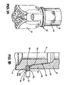
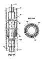
- a detachable housing 10 in accordance with one illustrative embodiment of the present invention is positioned between a first component 12 and a second component 14, each of which is adapted to be positioned in a subterranean hole.
- the first component 12 and second component 14 are coupled to one another by an illustrative threaded connection 16.
- the centerline 17 of the threaded connection 16 is depicted in Figure 1B.
- the first component 12 is an oilfield tubular, e.g., API pipe
- the second component 14 is an illustrative drill bit.
- the present invention may be positioned between any two downhole components.
- the housing 10 is positioned between an end surface 12a of the first component 12 and an end surface 14a of the second component 14. In some embodiments, one or both of the end surfaces 12a, 14a actually engage the housing 10. In some cases, a sealing interface may be provided between the housing 10 and at least one of the end surfaces 12a, 14a, although such a sealing interface may not be required in all embodiments of the present invention. Simply put, in some embodiments, the housing 10 is simply positioned between the end surfaces 12a, 14a, while in other cases, the end surfaces 12a, 14a engage and clamp the housing 10 in the position depicted in Figures 1A-1B. The distance 15 that the housing 10 extends beyond the outer surface 13 of the first component 12 may vary depending upon the particular application.
- one illustrative embodiment of the housing 10 is basically configured as a ring having an inner surface 10i, an outer surface 10o, a top surface 10t and a bottom surface 10b.
- An illustrative cavity 18 is formed in the housing 10.
- the housing 10 further comprises a cover plate 20 and seal 22 that is used to isolate the cavity 18 from the outside environment.
- the cover plate 20 is secured in place through use of a plurality of fasteners 24, e.g., screws.
- the cavity 18 may simply be a threaded opening and a threaded plug may act as the cover for the cavity 18.
- the housing 10 may be configured to have one or more devices positioned within the cavity 18.
- any of a variety of sensors and/or various electrical items may be positioned within the cavity 18.
- the housing 10 of the present invention may further comprise a passageway 32 (see Figure 2A) to allow sensing of downhole environmental conditions that exist outside of the housing 10, e.g., downhole pressure.
- the passageway 32 is not required in all embodiments of the present invention.
- the housing 10 may vary depending upon the particular application.
- the housing 10 is essentially a ring having a radial width 26 and a thickness 28.
- the width 26 and thickness 28 may vary depending upon the particular application. In general, the radial width 26 will be at least approximately one inch, and may be as wide as can be accommodated by the particular application. Similarly, in one illustrative embodiment, the thickness 28 may be approximately 1.5 inches or thicker.
- the size, shape and configuration of the cavity 18 may also vary. In the illustrative embodiment depicted in Figures 2A-2C, the cavity 18 is essentially a rectangular compartment. Of course, other configurations are possible, e.g., a cylindrical shaped cavity.
- the housing 10 may have at least one device, e.g., at least one sensor and/or at least one item of electrical equipment, positioned in the cavity 18.
- a plurality of devices 29 are shown positioned within the cavity 18. More specifically, in the depicted embodiment, the devices 29 comprise sensors 30 and a plurality of electrical components 31 that are mounted on a surface 18a of the cavity 18. It should be understood that the depicted sensors 30 and electrical components 31 are schematic and illustrative in nature.
- some of the devices employed in obtaining downhole data may be mounted in or on another structure, e.g., a drill bit, and the cavity 18 may contain only various electrical components. In other cases, only sensors are mounted within the cavity 18 and the electrical components are positioned elsewhere, e.g., a downhole sub.
- sensors 30 and/or electrical components 31 are coupled together so as to obtain the desired data are well known to those skilled in the art and thus will not be described in any greater detail herein.
- the sensors 30 and the electrical components 31 may be mounted to the surface 18a by a variety of known techniques, e.g., gluing, use of a potting compound, etc.
- the surface 18a is depicted as having the sensors 30 and the electrical components 31 mounted thereon, such items may be mounted on any or all of the surfaces of the cavity 18 depending upon the particular application.
- the present invention should not be considered as limited to any particular type of sensor 30 or electrical component 31 or how such items are mounted within the cavity 18 of the housing 10 of the present invention.
- the present invention may be used to facilitate the acquisition of data regarding any of a variety of different types of downhole data or information, including, for example, formation type, well temperature, well pressure, drill bit accelerations, velocities and displacements, drill bit inclination and azimuth, drill bit axial load and rotational torque, drill bit rotary speed and rate of penetration, etc.
- the present invention may also be employed to acquire ring compression data that may be indicative of successful make-up. Strain gauges may be employed in such an illustrative application.
- the present invention may also be employed to acquire data relating to drill pipe accelerations as well as data relating to the dynamic behavior of any bottom hole assembly (BHA).
- BHA bottom hole assembly
- sensing devices that may be positioned within the cavity 18 include any of a variety of different types of mechanical and/or electrical sensors, e.g., thermometers, gyroscopes, strain gauges, accelerometers, barometers, pressure sensors, hall effect switches, etc.
- electrical components that may be positioned within the cavity 18 include, but are not limited to, a battery, a microprocessor, a memory unit or chip, a circuit board, a communications port, and/or an analog-to-digital converter, etc. If desired or necessary, a plurality of such components may be positioned within the cavity 18, e.g., multiple batteries.
- the sensors 30 and electrical components 31 may be coupled together in any of a variety of known techniques.
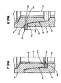
- Figure 3 depicts an alternative arrangement wherein at least a portion of the housing 10 of the present invention is positioned between the first component 12 and the second component 14.
- the second component 14 is provided with a stepped profile comprised of an end surface 14a, a side surface 14b, and an end surface 14c.
- the end surface 12a of the first component 12 engages the surface 14c of the second component 14 while still maintaining the housing 10 of the present invention between the end surface 12a of the first component 12 and the end surface 14a of the second component 14.
- Figure 4 is yet another alternative configuration of the present invention wherein the housing 10 is mounted adjacent the interior surfaces 19 of the first component 12 and the second component 14. More specifically, the illustrative housing 10 depicted therein is positioned between an end surface 12b of the first component 12 and an end surface 14d of the second component 14 that are formed on the interior side of the threaded connection 16.
- the present invention should not be considered as limited to any particular location of the housing 10 relative to the first and second components 12, 14 unless such limitations are expressly set forth in the appended claims.
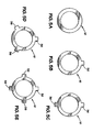
- Figures 5A-5E are plan views depicting various illustrative configurations of the housing 10 of the present invention.
- Figure 5A depicts the illustrative example where the housing 10 is essentially configured as a ring. In some cases, if a pure ring configuration were employed for the housing 10, it may tend to block or restrict fluid flow around the ring. For example, in the application where the housing 10 is placed above a drill bit, circulating mud returning to the surface in the annulus defined between the drill pipe and the wellbore circulates past the housing 10. In such an application, it may be desirable to have as little of the housing 10 positioned in the flow path of the returning fluid as possible.
- the housing 10 of the present invention may be provided with one or more blades or projections 36 in a variety of different configurations that tend to reduce the amount of the housing 10 in any particular flow path.
- Figures 5B, 5C, 5D and 5E present illustrative embodiments wherein the housing 10 has, respectively, one, two, three, and four projections 36.
- the size, shape and configuration of the projections 36 may vary depending upon the application.
- the cavity 18 may be formed in the projections 36 or in other areas of the housing 10 where the projections 36 do not exist. In some cases, a cavity 18 may be formed in each of the projections 36, although that is not required in all embodiments.
- Figures 6A-6C depict illustrative examples of the positioning of a cavity 18 in the housing 10.
- a cavity 18 is formed in a projection 36 that is part of the housing 10.
- the cavity 18 is formed such that it opens onto the interior surface l0i of the housing 10.
- the cavity 18 is formed such that it opens onto the top surface 10t of the housing 10.
- the cover plate 20 is not depicted in Figures 6A and 6C.
- one of the end surfaces, e.g., 12a, 14a can engage the housing 10 and cover the cavity 18, thereby eliminating the need for the cover plate 20.
- Figure 6D depicts yet another illustrative embodiment of the housing 10 wherein a plurality of cavities 18 are formed in the housing 10 and the cavities are connected to one another with internal passageways 37.
- the devices e.g., electrical components 31 and/or sensors 30, positioned in the various cavities 18 may be coupled to one another via wires positioned in the passageways 37.
- all of the cavities 18 may not need to be interconnected together by the passageways 37.
- the present invention should not be considered as limited to the illustrative embodiment depicted in Figure 6D unless such limitations are expressly set forth in the appended claims.
- FIG. 7 depicts yet another alternative embodiment of the housing 10 of the present invention.
- the housing 10 has an attachment lip 38.
- the attachment lip 38 is positioned between the end surface 12a of the first component 12 and the end surface 14 of the second component 14.
- the attachment lip 38 may have a radial width of approximately 0.5 inches and a thickness of approximately 0.25 inches.
- Figure 8 depicts an illustrative embodiment of the present invention wherein the end surface 12a of the first component 12 is sealingly engaged with the top surface 10t of the housing 10.
- additional sealing e.g., an O-ring
- an O ⁇ ring or other like seal may be positioned around the cavity 18 and a seal established between the O ⁇ ring and the end surface 12a of the first component 12. In the latter case, there may not be a metal-to-metal seal created between the end surface 12a and the top surface 10t of the housing 10.
- the housing 10 may also be provided with one or more indicator lights and/or display panels for various purposes.
- Figure 9 schematically depicts an illustrative embodiment of the housing 10 with a plurality of indicator lights 40 and a display panel 42 positioned thereon.
- Such components may be positioned such that they may be viewed by an operator looking at the outside of the housing 10 or they may be positioned within one or more of the cavities 18 formed in the housing 10.
- the indicator lights 40 and the display panel 42 may be viewed from the outside, such as when the housing 10 is retrieved from downhole.
- the indicator lights 40 and/or display panel 42 may be employed in a variety of different contexts.
- a control logic may be established such that an indicator light is "on” only when a sensed parameter, e.g., temperature, pressure, torque, etc., exceeds a preselected allowable limit or range, i.e., the indicator light can indicate an out-of-tolerance or problem condition.
- the control logic may be established such that the indicator light is always “on” and only goes off when an out-of-tolerance condition is sensed.
- Colored indicator lights may also be employed with the present invention, e.g., red and green lights, wherein the red light indicated an out-of-tolerance condition and the green light indicated a within-tolerance condition.
- the use of such indicator lights may be very useful. For example, through use of the indicator lights 40, an out-of-tolerance event may be quickly identified as soon as the housing 10 is removed from the borehole. In that case, analysis of the data acquired by the devices in the housing 10, e.g., sensors, may be given a very high priority as an out-of-tolerance condition is indicated. Absent the use of such good/bad indicator lights, the analysis of the acquired data may be delayed. Such delays may be very problematic in many situations if corrective actions are delayed.
- the indicator lights 40 may be LED devices that are commonly found in the industry.
- the lights 40 may be electrically coupled to the equipment, e.g., electrical components 31 and/or sensors 30 positioned in the cavities 18 in the housing 10.
- the lights 40 may be actuated by known circuitry positioned within the cavities 18.
- the control logic used to actuate the lights 40 may be embedded in various circuits formed on the electrical components 31 positioned within the cavities 18, e.g., a microprocessor, a programmable logic device, etc.
- the housing 10 may also be provided with one or more display panels 42.
- the display panel 42 may be, for example, an LED display panel.
- the panel 42 may provide information with respect to one or more variables.
- the display panel displays the highest temperature sensed during the downhole operation.
- the display panel 42 could also indicate other variables, such as maximum downhole pressure, maximum or average torque values, etc.
- the display panel 42 may be coupled to one or more electrical components 31 and/or sensors 30 positioned in the cavities 18 formed in the housing 10.
- housing 10 will require that there be sufficient standoff 21 (see Figure 1B) between the components 12, 14 to allow the housing 10 to be positioned therein.
- standoff 21 see Figure 1B
- the housing 10 of the present invention may not be employed in all such situations.
- a spacer that is equivalent in size to the housing 10 may be positioned between the first and second components 12, 14 such that the mechanical integrity of the connection between the first and second components is maintained.
- Such a spacer element may not have a cavity 18 formed therein.
- the housing 10 of the present invention is positioned between the first and second components 12, 14 before the components are mated together.
- completing the threaded connection 16 clamps the housing 10 between the surfaces of the components 12, 14, e.g., the housing 10 is clamped between the end surfaces 12a and 14a depicted in Figure 1.
- the components 12, 14 and the housing 10 are positioned downhole and data is acquired regarding, for example, various downhole environmental conditions or positional information. In one illustrative embodiment, this data is stored in a memory unit or chip positioned within the cavity 18.
- the housing 10 is brought uphole and the information regarding the acquired data is downloaded and used for any of a variety of research, development or production reasons.
- the downloading of the acquired information may be accomplished by an electrical connection or by wireless interrogation using a radio or infrared device.
- the housing 10 of the present invention may be employed wherein the data obtained by the sensor(s) positioned within the cavity 18 is sent to the surface on a real-time, or near real-time, basis.
- a communication link between the surface and the sensors 30 and/or electrical components 31 within the cavity 18 is provided and data is transmitted to the surface on a real-time or near real-time basis.
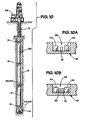
- FIG. 10 depicts another illustrative embodiment of the present invention.
- a plurality of detachable housings 10 of the present invention may be positioned at various spaced-apart locations along a drill string 50 having an illustrative drill bit 14 positioned at the end thereof
- the drill string 50 is comprised of many sections of standard un-wired pipe.
- data may be sensed by various sensors (not shown in Figure 10) positioned proximate the drill bit and/or in one or more cavities 18 formed in the housing 10 proximate the drill bit 14.
- the housing 10 proximate the drill bit 14 also contains a schematically depicted wireless transmitter 52 for transmitting data regarding the information or parameters sensed downhole.
- Each of the other housings 10 contain a transmitter 52 and a schematically depicted receiver 54 that is adapted to receive wireless transmissions from the transmitter 52 in an adjacent housing 10.
- the housing 10 proximate the drill bit 14 may also have a wireless receiver 54.
- the spaced-apart housings 10 may be used as relay stations to wirelessly transmit data acquired downhole to a surface location 56. In this manner, the data acquired downhole may be sent to the surface on a real-time or near-real-time basis.
- the control circuitry and power source for the transmitter 52 and receiver 54 may be contained in the cavities 18 formed in the various housings 10.
- the plurality of housings 10 may be spaced apart any desired distance that is consistent with reliable receipt and transmission of wireless data. That is, there may be multiple sections of pipe positioned between adjacent housings 10.
- FIGS 11A-11B depict yet another illustrative embodiment of the present invention.
- a drill string 60 is comprised of multiple sections of wired pipe 62 and a downhole device 64 positioned between sections of wired pipe 62.
- a plurality of housings 10' of the present invention are depicted in the wired pipe sections 62.
- Data wires 66 are schematically depicted in the wired pipe sections 62.
- data may be transmitted along the data wires 66 embedded within the wired pipe 62.
- the lengths of wired pipe 62 may be provided with an inductive coil 69 on both ends of each section of wired pipe 62 such that data may be transmitted from one section of pipe to another after the sections are joined together.
- an inductive coil 68 is formed in at least one end of the housing 10'.
- Each of the housings 10' may further comprise a wireless transmitter 52 and a wireless receiver 54 as discussed above with reference to the embodiment shown in Figure 10.
- the housings 10' are used to wirelessly transmit data from one section of wired pipe 62 to another spaced-apart section of wired pipe 62.
- the downhole device 64 is not wired, and may not be capable of being wired, e.g., a stabilizer.
- the transmitter and receiver in each of the housings 10' may be used to bypass the un-wired downhole device or assembly.
- the present invention is directed to a housing for equipment that may be employed in obtaining downhole measurement data.
- the apparatus disclosed herein comprises a first component adapted to be positioned in a subterranean hole, a second component adapted to be positioned in the subterranean hole, and a detachable housing, at least a portion of which is clamped between the first and second components, the housing having at least one cavity formed therein and at least one device positioned within the at least one cavity.
- the apparatus comprises a first component adapted to be positioned in a subterranean hole having an end surface, a second component adapted to be positioned in the subterranean hole having an end surface, the first and second components being threadingly coupled to one another, and a detachable housing, at least a portion of which is positioned between the end surfaces of the first and second components, the housing having at least one cavity formed therein and at least one device positioned within the at least one cavity.
- the apparatus comprises a threaded pipe having an end surface, a drill bit having an end surface, the pipe and the drill bit being threadingly coupled to one another, and a detachable housing, at least a portion of which is positioned between the end surfaces of the threaded pipe and the drill bit, the housing having at least one cavity formed therein and at least one device positioned within the at least one cavity.
- the method comprises positioning at least a portion of a detachable housing between an end surface of a first component adapted to be positioned in a subterranean hole and an end surface of a second component adapted to be positioned in the subterranean hole, the housing having at least one cavity formed therein and at least one device positioned within the at least one cavity, threadingly coupling the first and second components to one another, thereby securing the housing between the first and second components, positioning the first component, the second component and the housing in a subterranean hole, and acquiring data using the at least one device after the housing is positioned within the subterranean hole.
Landscapes
- Engineering & Computer Science (AREA)
- Physics & Mathematics (AREA)
- Life Sciences & Earth Sciences (AREA)
- Geology (AREA)
- Mining & Mineral Resources (AREA)
- Geophysics (AREA)
- Environmental & Geological Engineering (AREA)
- Fluid Mechanics (AREA)
- General Life Sciences & Earth Sciences (AREA)
- Geochemistry & Mineralogy (AREA)
- Remote Sensing (AREA)
- Arrangements For Transmission Of Measured Signals (AREA)
Abstract
Description
Claims (26)
- An apparatus, comprising:a first component adapted to be positioned in a subterranean hole;a second component adapted to be positioned in said subterranean hole;a detachable housing, at least a portion of which is clamped between said first and second components, said housing having at least one cavity formed therein; andat least one device positioned within said at least one cavity.
- The apparatus of claim 1, wherein said at least one device is comprised of at least one sensor.
- The apparatus of claim 2, wherein said at least one sensor is comprised of at least one of a thermometer, a gyroscope, an accelerometer, a strain gauge, a barometer, a pressure sensor and a hall effect switch.
- The apparatus of any of claims 1 to 3, wherein said at least one device is comprised of at least one electrical component.
- The apparatus of claim 4, wherein said at least one electrical component comprises at least one of a battery, a microprocessor, a wireless transmitter, a wireless receiver, a circuit board, an analog-to-digital converter, a communications port and a memory chip.
- The apparatus of any of the preceding claims, wherein said first and second components are threadingly coupled to one another.
- The apparatus of any of the preceding claims, wherein said first component comprises at least one of a threaded pipe and a drill bit.
- The apparatus of any of the preceding claims, wherein said second component comprises at least one of a threaded pipe and a drill bit.
- The apparatus of any of the preceding claims, wherein an end surface of said first component and an end surface of said second component engage said housing.
- The apparatus of any of the preceding claims, wherein said housing has a plurality of cavities formed therein.
- The apparatus of claim 10, wherein at least one said device is positioned in each of said plurality of cavities.
- The apparatus of any of the preceding claims, wherein said housing is positioned adjacent an exterior surface of said first component.
- The apparatus of any of the preceding claims, wherein said housing is positioned adjacent an interior surface of said first component.
- The apparatus of any of the preceding claims, wherein said at least one cavity has at least one of a generally cylindrical configuration and a generally rectangular configuration.
- The apparatus of any of the preceding claims, further comprising a cover plate positioned over said at least one cavity.
- The apparatus of any of the preceding claims, further comprising at least one passageway extending from said at least one cavity to an external surface of said housing.
- The apparatus of claim 10, further comprising an internal passageway formed in said housing that connects at least two of said plurality of cavities to one another.
- The apparatus of any of the preceding claims, wherein said housing comprises an attachment lip that is clamped between said first and second components.
- The apparatus of any of the preceding claims, wherein said housing is configured as a ring.
- The apparatus of any of the preceding claims, wherein said housing further comprises at least one projection, a cavity formed in said at least one projection, and at least one device positioned in said cavity formed in said projection.
- The apparatus of any of the preceding claims, wherein an end surface of at least one of said first and second components is positioned over said at least one cavity and is sealingly engaged with a surface of said housing.
- The apparatus of any of the preceding claims, further comprising at least one indicator light coupled to said housing.
- The apparatus of any of the preceding claims, further comprising at least one display panel coupled to said housing.
- The apparatus of claim 22, wherein said at least one indicator light is coupled to an exterior surface of said housing.
- The apparatus of claim 23, wherein said at least one display panel is coupled to an exterior surface of said housing.
- A method, comprising:positioning at least a portion of a detachable housing of an apparatus according to any of the preceding claims between an end surface of a first component thereof adapted to be positioned in a subterranean hole and an end surface of a second component thereof adapted to be positioned in said subterranean hole, the housing having at least one cavity formed therein and at least one device positioned within said at least one cavity;threadingly coupling said first and second components to one another, thereby securing said housing between said first and second components;positioning said first component, said second component and said housing in said subterranean hole; andacquiring data using said at least one device after said housing is positioned within said subterranean hole.
Applications Claiming Priority (2)
| Application Number | Priority Date | Filing Date | Title |
|---|---|---|---|
| US10/709,625 US20050257961A1 (en) | 2004-05-18 | 2004-05-18 | Equipment Housing for Downhole Measurements |
| US709625 | 2004-05-18 |
Publications (2)
| Publication Number | Publication Date |
|---|---|
| EP1598519A2 true EP1598519A2 (en) | 2005-11-23 |
| EP1598519A3 EP1598519A3 (en) | 2006-03-01 |
Family
ID=34941269
Family Applications (1)
| Application Number | Title | Priority Date | Filing Date |
|---|---|---|---|
| EP05252922A Withdrawn EP1598519A3 (en) | 2004-05-18 | 2005-05-12 | Equipment housing for downhole measurements |
Country Status (2)
| Country | Link |
|---|---|
| US (1) | US20050257961A1 (en) |
| EP (1) | EP1598519A3 (en) |
Cited By (3)
| Publication number | Priority date | Publication date | Assignee | Title |
|---|---|---|---|---|
| WO2006087239A1 (en) * | 2005-02-21 | 2006-08-24 | Diamant Drilling Services Sa | Device for monitoring a drilling or coring operation and installation comprising such a device |
| WO2009032504A1 (en) * | 2007-08-31 | 2009-03-12 | Schlumberger Canada Limited | Transducer assemblies for subsurface logging use |
| CN103670377A (en) * | 2013-11-08 | 2014-03-26 | 常州凯锐自动化控制设备有限公司 | Double-sensor pressure gauge for underground coal-bed gas |
Families Citing this family (19)
| Publication number | Priority date | Publication date | Assignee | Title |
|---|---|---|---|---|
| US20080202742A1 (en) * | 2007-02-27 | 2008-08-28 | Hall David R | Open Cavity in a Pocket of a Downhole Tool String Component |
| US7878266B2 (en) * | 2007-08-24 | 2011-02-01 | Halliburton Energy Services, Inc. | Downhole force measurement |
| NO330489B1 (en) * | 2008-04-03 | 2011-04-26 | Odfjell Casing Services As | Device for recording rotational parameters when joining rudder string |
| US8091627B2 (en) * | 2009-11-23 | 2012-01-10 | Hall David R | Stress relief in a pocket of a downhole tool string component |
| EP2505769B1 (en) * | 2011-03-30 | 2013-11-06 | Welltec A/S | Service panel |
| MX2016006824A (en) | 2013-12-27 | 2016-09-07 | Halliburton Energy Services Inc | Threaded connection with high bend and torque capacities. |
| GB2548101A (en) * | 2016-03-07 | 2017-09-13 | Shanghai Hengxu Mat Co Ltd | Downhole tool |
| GB201622186D0 (en) | 2016-12-23 | 2017-02-08 | Weatherford Uk Ltd | Antenna for downhole communication |
| GB2593614B (en) | 2019-02-22 | 2022-12-07 | Halliburton Energy Services Inc | An expanding metal sealant for use with multilateral completion systems |
| AU2019459040B2 (en) * | 2019-07-31 | 2025-05-29 | Halliburton Energy Services, Inc. | Methods to monitor a metallic sealant deployed in a wellbore, methods to monitor fluid displacement, and downhole metallic sealant measurement systems |
| US10961804B1 (en) | 2019-10-16 | 2021-03-30 | Halliburton Energy Services, Inc. | Washout prevention element for expandable metal sealing elements |
| US11519239B2 (en) | 2019-10-29 | 2022-12-06 | Halliburton Energy Services, Inc. | Running lines through expandable metal sealing elements |
| US12480373B2 (en) | 2019-11-13 | 2025-11-25 | Halliburton Energy Services, Inc. | Actuating a downhole device with a reactive metal |
| US11761290B2 (en) | 2019-12-18 | 2023-09-19 | Halliburton Energy Services, Inc. | Reactive metal sealing elements for a liner hanger |
| US11499399B2 (en) | 2019-12-18 | 2022-11-15 | Halliburton Energy Services, Inc. | Pressure reducing metal elements for liner hangers |
| US11761293B2 (en) | 2020-12-14 | 2023-09-19 | Halliburton Energy Services, Inc. | Swellable packer assemblies, downhole packer systems, and methods to seal a wellbore |
| US11572749B2 (en) | 2020-12-16 | 2023-02-07 | Halliburton Energy Services, Inc. | Non-expanding liner hanger |
| US11578498B2 (en) | 2021-04-12 | 2023-02-14 | Halliburton Energy Services, Inc. | Expandable metal for anchoring posts |
| US11879304B2 (en) | 2021-05-17 | 2024-01-23 | Halliburton Energy Services, Inc. | Reactive metal for cement assurance |
Family Cites Families (23)
| Publication number | Priority date | Publication date | Assignee | Title |
|---|---|---|---|---|
| US3864968A (en) * | 1973-05-14 | 1975-02-11 | Schlumberger Technology Corp | Force-measuring apparatus for use in a well bore pipe string |
| US4494072A (en) * | 1980-04-21 | 1985-01-15 | Exploration Logging, Inc. | Well logging apparatus with replaceable sensor carrying insulating sleeve disposed in rotation restrained position around a drill string |
| US4550392A (en) * | 1982-03-08 | 1985-10-29 | Exploration Logging, Inc. | Apparatus for well logging telemetry |
| US4628995A (en) * | 1985-08-12 | 1986-12-16 | Panex Corporation | Gauge carrier |
| US4972709A (en) * | 1988-10-03 | 1990-11-27 | Bailey Jr James R | Pump control system, level sensor switch and switch housing |
| US5235285A (en) * | 1991-10-31 | 1993-08-10 | Schlumberger Technology Corporation | Well logging apparatus having toroidal induction antenna for measuring, while drilling, resistivity of earth formations |
| US5265680A (en) * | 1992-10-09 | 1993-11-30 | Atlantic Richfield Company | Method for installing instruments in wells |
| US6230822B1 (en) * | 1995-02-16 | 2001-05-15 | Baker Hughes Incorporated | Method and apparatus for monitoring and recording of the operating condition of a downhole drill bit during drilling operations |
| US6571886B1 (en) * | 1995-02-16 | 2003-06-03 | Baker Hughes Incorporated | Method and apparatus for monitoring and recording of the operating condition of a downhole drill bit during drilling operations |
| EP0728915B1 (en) * | 1995-02-16 | 2006-01-04 | Baker Hughes Incorporated | Method and apparatus for monitoring and recording of operating conditions of a downhole drill bit during drilling operations |
| FR2739893B1 (en) * | 1995-10-17 | 1997-12-12 | Inst Francais Du Petrole | DEVICE FOR EXPLORING AN UNDERGROUND FORMATION CROSSED BY A HORIZONTAL WELL COMPRISING SEVERAL SENSORS PERMANENTLY COUPLED WITH THE WALL |
| US5973317A (en) * | 1997-05-09 | 1999-10-26 | Cidra Corporation | Washer having fiber optic Bragg Grating sensors for sensing a shoulder load between components in a drill string |
| US6443228B1 (en) * | 1999-05-28 | 2002-09-03 | Baker Hughes Incorporated | Method of utilizing flowable devices in wellbores |
| WO2002006716A1 (en) * | 2000-07-19 | 2002-01-24 | Novatek Engineering Inc. | Data transmission system for a string of downhole components |
| GB2382830A (en) * | 2000-09-08 | 2003-06-11 | Baker Hughes Inc | Gravel pack expanding valve |
| AU2001212268A1 (en) * | 2000-10-23 | 2002-05-06 | Halliburton Energy Services, Inc. | Fluid property sensors and associated methods of calibrating sensors in a subterranean well |
| US6722450B2 (en) * | 2000-11-07 | 2004-04-20 | Halliburton Energy Svcs. Inc. | Adaptive filter prediction method and system for detecting drill bit failure and signaling surface operator |
| US6712160B1 (en) * | 2000-11-07 | 2004-03-30 | Halliburton Energy Services Inc. | Leadless sub assembly for downhole detection system |
| US6850068B2 (en) * | 2001-04-18 | 2005-02-01 | Baker Hughes Incorporated | Formation resistivity measurement sensor contained onboard a drill bit (resistivity in bit) |
| US6910534B2 (en) * | 2002-06-11 | 2005-06-28 | Halliburton Energy Services, Inc. | Apparatus for attaching a sensor to a tubing string |
| US6814162B2 (en) * | 2002-08-09 | 2004-11-09 | Smith International, Inc. | One cone bit with interchangeable cutting structures, a box-end connection, and integral sensory devices |
| US6918293B2 (en) * | 2003-04-09 | 2005-07-19 | Halliburton Energy Services, Inc. | System and method having radiation intensity measurements with standoff correction |
| US7252152B2 (en) * | 2003-06-18 | 2007-08-07 | Weatherford/Lamb, Inc. | Methods and apparatus for actuating a downhole tool |
-
2004
- 2004-05-18 US US10/709,625 patent/US20050257961A1/en not_active Abandoned
-
2005
- 2005-05-12 EP EP05252922A patent/EP1598519A3/en not_active Withdrawn
Cited By (9)
| Publication number | Priority date | Publication date | Assignee | Title |
|---|---|---|---|---|
| WO2006087239A1 (en) * | 2005-02-21 | 2006-08-24 | Diamant Drilling Services Sa | Device for monitoring a drilling or coring operation and installation comprising such a device |
| BE1016460A3 (en) * | 2005-02-21 | 2006-11-07 | Diamant Drilling Services Sa | Device for monitoring a drilling operation or core drilling and equipment including such device. |
| GB2438343A (en) * | 2005-02-21 | 2007-11-21 | Diamant Drilling Services Sa | Device for monitoring a drilling or coring operation and installation comprising such a device |
| GB2438343B (en) * | 2005-02-21 | 2009-11-25 | Diamant Drilling Services Sa | Device for monitoring a drilling or coring operation and installation comprising such a device |
| WO2009032504A1 (en) * | 2007-08-31 | 2009-03-12 | Schlumberger Canada Limited | Transducer assemblies for subsurface logging use |
| US7723989B2 (en) | 2007-08-31 | 2010-05-25 | Schlumberger Technology Corporation | Transducer assemblies for subsurface use |
| CN101377129B (en) * | 2007-08-31 | 2012-07-18 | 普拉德研究及开发股份有限公司 | Transducer assemblies for subsurface logging use |
| EA017430B1 (en) * | 2007-08-31 | 2012-12-28 | Шлюмбергер Текнолоджи Б.В. | Transducer assemblies for subsurface logging use |
| CN103670377A (en) * | 2013-11-08 | 2014-03-26 | 常州凯锐自动化控制设备有限公司 | Double-sensor pressure gauge for underground coal-bed gas |
Also Published As
| Publication number | Publication date |
|---|---|
| US20050257961A1 (en) | 2005-11-24 |
| EP1598519A3 (en) | 2006-03-01 |
Similar Documents
| Publication | Publication Date | Title |
|---|---|---|
| EP1598519A2 (en) | Equipment housing for downhole measurements | |
| US20060065395A1 (en) | Removable Equipment Housing for Downhole Measurements | |
| EP2478183B1 (en) | Monitoring drilling performance in a sub-based unit | |
| US20190345779A1 (en) | Coil tubing bottom hole assembly with real time data stream | |
| US20120043069A1 (en) | Downhole wireline wireless communication | |
| CA3055546C (en) | Wireless communication between downhole components and surface systems | |
| CA2695165A1 (en) | Instrumented wellbore tools and methods | |
| US20100258351A1 (en) | System, method and apparatus for downhole system having integrated measurement while operating components | |
| US11795809B2 (en) | Electronics enclosure for downhole tools | |
| RU2552249C2 (en) | Port of light connection for use on well instruments | |
| US7878266B2 (en) | Downhole force measurement | |
| CA2920404C (en) | Downhole probe assembly with bluetooth device | |
| WO2013082376A1 (en) | Pressure actuated centralizer | |
| US20210131265A1 (en) | Measurement of Torque with Shear Stress Sensors | |
| US20210404319A1 (en) | Integrated collar sensor for measuring mechanical impedance of the downhole tool | |
| US20170067336A1 (en) | Antennas for a drilling system and method of making same | |
| US11149536B2 (en) | Measurement of torque with shear stress sensors | |
| US20210404317A1 (en) | Integrated collar sensor for measuring performance characteristics of a drill motor | |
| US20240200437A1 (en) | Instrumented sub | |
| US20220049597A1 (en) | Integrated collar sensor for measuring health of a downhole tool |
Legal Events
| Date | Code | Title | Description |
|---|---|---|---|
| PUAI | Public reference made under article 153(3) epc to a published international application that has entered the european phase |
Free format text: ORIGINAL CODE: 0009012 |
|
| AK | Designated contracting states |
Kind code of ref document: A2 Designated state(s): AT BE BG CH CY CZ DE DK EE ES FI FR GB GR HU IE IS IT LI LT LU MC NL PL PT RO SE SI SK TR |
|
| AX | Request for extension of the european patent |
Extension state: AL BA HR LV MK YU |
|
| PUAL | Search report despatched |
Free format text: ORIGINAL CODE: 0009013 |
|
| AK | Designated contracting states |
Kind code of ref document: A3 Designated state(s): AT BE BG CH CY CZ DE DK EE ES FI FR GB GR HU IE IS IT LI LT LU MC NL PL PT RO SE SI SK TR |
|
| AX | Request for extension of the european patent |
Extension state: AL BA HR LV MK YU |
|
| 17P | Request for examination filed |
Effective date: 20060721 |
|
| 17Q | First examination report despatched |
Effective date: 20060907 |
|
| AKX | Designation fees paid |
Designated state(s): AT BE BG CH CY CZ DE DK EE ES FI FR GB GR HU IE IS IT LI LT LU MC NL PL PT RO SE SI SK TR |
|
| STAA | Information on the status of an ep patent application or granted ep patent |
Free format text: STATUS: THE APPLICATION IS DEEMED TO BE WITHDRAWN |
|
| 18D | Application deemed to be withdrawn |
Effective date: 20070118 |