EP1598512A2 - Refrigerator - Google Patents
Refrigerator Download PDFInfo
- Publication number
- EP1598512A2 EP1598512A2 EP05250645A EP05250645A EP1598512A2 EP 1598512 A2 EP1598512 A2 EP 1598512A2 EP 05250645 A EP05250645 A EP 05250645A EP 05250645 A EP05250645 A EP 05250645A EP 1598512 A2 EP1598512 A2 EP 1598512A2
- Authority
- EP
- European Patent Office
- Prior art keywords
- link
- door
- piston
- refrigerator
- cam
- Prior art date
- Legal status (The legal status is an assumption and is not a legal conclusion. Google has not performed a legal analysis and makes no representation as to the accuracy of the status listed.)
- Withdrawn
Links
Images



Classifications
-
- F—MECHANICAL ENGINEERING; LIGHTING; HEATING; WEAPONS; BLASTING
- F25—REFRIGERATION OR COOLING; COMBINED HEATING AND REFRIGERATION SYSTEMS; HEAT PUMP SYSTEMS; MANUFACTURE OR STORAGE OF ICE; LIQUEFACTION SOLIDIFICATION OF GASES
- F25D—REFRIGERATORS; COLD ROOMS; ICE-BOXES; COOLING OR FREEZING APPARATUS NOT OTHERWISE PROVIDED FOR
- F25D23/00—General constructional features
- F25D23/02—Doors; Covers
-
- F—MECHANICAL ENGINEERING; LIGHTING; HEATING; WEAPONS; BLASTING
- F25—REFRIGERATION OR COOLING; COMBINED HEATING AND REFRIGERATION SYSTEMS; HEAT PUMP SYSTEMS; MANUFACTURE OR STORAGE OF ICE; LIQUEFACTION SOLIDIFICATION OF GASES
- F25D—REFRIGERATORS; COLD ROOMS; ICE-BOXES; COOLING OR FREEZING APPARATUS NOT OTHERWISE PROVIDED FOR
- F25D23/00—General constructional features
- F25D23/02—Doors; Covers
- F25D23/028—Details
-
- E—FIXED CONSTRUCTIONS
- E05—LOCKS; KEYS; WINDOW OR DOOR FITTINGS; SAFES
- E05F—DEVICES FOR MOVING WINGS INTO OPEN OR CLOSED POSITION; CHECKS FOR WINGS; WING FITTINGS NOT OTHERWISE PROVIDED FOR, CONCERNED WITH THE FUNCTIONING OF THE WING
- E05F3/00—Closers or openers with braking devices, e.g. checks; Construction of pneumatic or liquid braking devices
- E05F3/04—Closers or openers with braking devices, e.g. checks; Construction of pneumatic or liquid braking devices with liquid piston brakes
- E05F3/10—Closers or openers with braking devices, e.g. checks; Construction of pneumatic or liquid braking devices with liquid piston brakes with a spring, other than a torsion spring, and a piston, the axes of which are the same or lie in the same direction
-
- E—FIXED CONSTRUCTIONS
- E05—LOCKS; KEYS; WINDOW OR DOOR FITTINGS; SAFES
- E05Y—INDEXING SCHEME ASSOCIATED WITH SUBCLASSES E05D AND E05F, RELATING TO CONSTRUCTION ELEMENTS, ELECTRIC CONTROL, POWER SUPPLY, POWER SIGNAL OR TRANSMISSION, USER INTERFACES, MOUNTING OR COUPLING, DETAILS, ACCESSORIES, AUXILIARY OPERATIONS NOT OTHERWISE PROVIDED FOR, APPLICATION THEREOF
- E05Y2900/00—Application of doors, windows, wings or fittings thereof
- E05Y2900/30—Application of doors, windows, wings or fittings thereof for domestic appliances
- E05Y2900/31—Application of doors, windows, wings or fittings thereof for domestic appliances for refrigerators
-
- F—MECHANICAL ENGINEERING; LIGHTING; HEATING; WEAPONS; BLASTING
- F25—REFRIGERATION OR COOLING; COMBINED HEATING AND REFRIGERATION SYSTEMS; HEAT PUMP SYSTEMS; MANUFACTURE OR STORAGE OF ICE; LIQUEFACTION SOLIDIFICATION OF GASES
- F25D—REFRIGERATORS; COLD ROOMS; ICE-BOXES; COOLING OR FREEZING APPARATUS NOT OTHERWISE PROVIDED FOR
- F25D2323/00—General constructional features not provided for in other groups of this subclass
- F25D2323/02—Details of doors or covers not otherwise covered
- F25D2323/024—Door hinges
-
- F—MECHANICAL ENGINEERING; LIGHTING; HEATING; WEAPONS; BLASTING
- F25—REFRIGERATION OR COOLING; COMBINED HEATING AND REFRIGERATION SYSTEMS; HEAT PUMP SYSTEMS; MANUFACTURE OR STORAGE OF ICE; LIQUEFACTION SOLIDIFICATION OF GASES
- F25D—REFRIGERATORS; COLD ROOMS; ICE-BOXES; COOLING OR FREEZING APPARATUS NOT OTHERWISE PROVIDED FOR
- F25D2400/00—General features of, or devices for refrigerators, cold rooms, ice-boxes, or for cooling or freezing apparatus not covered by any other subclass
- F25D2400/06—Refrigerators with a vertical mullion
Definitions
- the present invention relates to a refrigerator including a closure mechanism for biasing a door of the refrigerator into a closed state, wherein the closure mechanism comprises a piston slideable within a housing against the force of a biasing member when the door is opened so that the door closes when released.
- damping devices which provide the refrigerator doors with a smooth closing operation so as to absorb the shock generated upon closure of the doors.
- oil filled damping devices have conventionally been used.
- This kind of damping device however has a problem in that a sealing member thereof can often become worn due to the rectilinear reciprocation of a rod provided in a link mechanism.
- the link mechanism is horizontally mounted at the bottom of a refrigerator. To achieve the rectilinear reciprocation of the rod, the link mechanism must disadvantageously have long links.
- damping device requires a separate structure to be used to protect the oil damper as well as the links of the link mechanism.
- the conventional damping device is generally located at the bottom of a refrigerator housing so that the conventional damping device connects the refrigerator housing to a refrigerator door by cooperating with the link mechanism, to repair the damping device, the refrigerator housing has to be laid down on the ground after any contents have been removed, resulting in extreme inconvenience in repair and exchange thereof.
- the present invention seeks to provide a system which overcomes or substantially alleviates the problems discussed above.
- a refrigerator according to the present invention is characterised in that the closure mechanism comprises cooperating cam members that translates rotational movement of the door into linear movement of the piston.
- the closure mechanism comprises a shaft mounted in the housing, one end of the shaft protruding from the housing being connected via a linkage to the door so that the shaft rotates in response to movement of the door between its open and closed state.
- the cooperating cam members comprise a generally helically formed cam path on the shaft and a cam follower on the piston so that the cam follower follows the cam path when the shaft rotates to cause the piston to slide linearly within the housing.
- the biasing means is a spring.
- the piston has a hole therein to receive an elongate guide member fixed to the housing, the guide member sliding within the piston during movement of the piston when the door is opened and closed
- an aspect of the present invention may provide a refrigerator comprising a damping device of a refrigerator door which is mountable even in a narrow space by virtue of a reduced operating space of the damping device, and a simplified link device, which enables the damping device to be mounted to the refrigerator door without interference of other members.
- Another aspect of the invention may provide a refrigerator comprising a damping device, which is designed to be mounted in a separate space defined in a refrigerator door, resulting in simplicity in repair and exchange thereof.
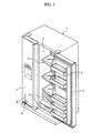
- FIG. 1 a refrigerator comprising a rectangular housing 1 that is open at a front side thereof, and doors 3 and 4 which are coupled to the housing 1 in a hingedly rotatable manner to allow access to the front side of the refrigerator.
- a door 3 or 4 is coupled to the housing 1 via a link mechanism 10 provided at an upper or lower end thereof.
- Damping devices 20 which ensure the smooth opening and closing operations of the doors 3 and 4 are connected to the link mechanism 10. Consequently, the damping devices 20 prevent shock from being applied to the housing 1.
- equal numbers of damping devices 20 are provided inside each of the doors 3 and 4.
- the interior of the refrigerator is divided into a left freezing chamber and a right refrigerating chamber which are both designated by reference numeral 2.
- a plurality of shelves 5 and storage containers 6 to store foods are provided inside the freezing and refrigerating chambers 2.
- Shelves 7 to store beverages or small containers are provided on the inner surfaces of the doors 3 and 4.
- the damping devices 20 are provided inside the doors 3 and 4 and each damping device 20 is mounted in a separate mounting space defined in the respective doors 3 and 4 so as to achieve convenience in repair and exchange thereof.
- a separate mounting space is defined in the lower portion of a front panel of the respective doors 3 and 4, but the position is not limited thereto.
- the position of the mounting space may be defined in other portions of the doors 3 and 4, or in the housing 1 as the damping device 20 of the present invention encounters substantially fewer spatial problems than a conventional link mechanism, which requires a wide horizontal space.
- Such a damping device 20 includes a link connecting portion 21 formed at one end which is inserted through a cylindrical guide portion 11a provided on a rectangular plate-shaped support member 11 so as to protrude out of the support member 11 through a centre opening 11b.
- the support member 11 is further provided with a plurality of bolt fastening holes 11c to enable the fastening of the support member 11 to the door 3 or 4.
- a first link member 12 is coupled to the link connecting portion 21 which protrudes out of the support member 11.
- the first link member 12 is bar shaped and has a first hole formed at one end thereof to be used in the coupling of the link connecting portion 21 and a second hole at the other end thereof to be used in the coupling of a second link member 15.
- the second link member 15 is bar shaped similar to the first link member 12. However, the second link member 15 is longer than the first link member 12. By using fasteners 13, 14 and 16 such as bolts, pins, nuts, etc. one end of the second link member 15 may be coupled to the first link member 12, and the other end of the second link member 15 coupled to a hinge member 17.
- the first and second link members 12 and 15 are made of a metallic material having strength and durability that is sufficient to endure the load of the refrigerator door.
- the hinge member 17 is a plate, but the shape is not limited thereto. As such, the hinge member 17 may have other appropriate shapes in consideration of the coupling relationship between the door 3 or 4 and the housing 1. One end of the hinge member 17 is fixed to the refrigerator housing 1 and the other end is fixed to the refrigerator door 3 or 4 by means of a hinge shaft 18. The hinge member 17 has an area that is sufficient to support the load of the refrigerator door.
- the hinge member 17 is formed with a threaded protrusion 17a to be used in the coupling of the second link member 15 and an opening 17b to enable the coupling of a hinge shaft coupling member 19.
- the hinge shaft coupling member 19 is fastened to the end of the bottom surface of the door 3 or 4.
- the hinge member 17 further includes a plurality of threaded holes 17c to allow the hinge member 17 to be firmly fastened to both the refrigerator doors 3 or 4 and the housing 1.
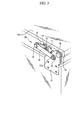
- the link mechanism 10 comprising the link members is coupled to the damping device 20 as shown in Figure 3.
- the damping device 20 is mounted inside the door 4 and the support member 11 is bolted to the lower end of the door 4 so that the link connecting portion 21 of the damping device 20 protrudes out of the support member 11 through the centre opening 11b.
- the first hole of the first link member 12 is fitted to the link connecting portion 21 and held in place by a nut.
- the second link member 15 is bolted to the first link member 12.
- the two link members 12 and 15 move according to the opening and closing operations of the refrigerator door. Therefore, in order to relieve the friction that occurs during rotation of the doors 3 or 4 between the first and second link members 12 and 15, a washer is interposed between the first and second link members 12 and 15.
- the second link member 15 is fixedly coupled to the hinge member 17 wherein one of the holes thereof is fitted around the protrusion 17a of the hinge member 17 and held in place with a nut.
- the hinge shaft 18 is fitted through the opening 17b of the hinge member 17.
- the hinge shaft 18 is further fitted in a hinge shaft opening 19a of the hinge shaft coupling member 19 which would have been previously fastened to the end of the bottom surface of the refrigerator door so as to attach the hinge member 17 to the door.
- the threaded holes 17c of the hinge member 17 are bolted to corresponding holes formed at the refrigerator housing 1 so as to allow the hinge member 17 to be firmly fastened to the refrigerator housing 1.
- the hinge shaft coupling member 19 having the hinge shaft opening 19a which is provided at the end of the bottom surface of the refrigerator door, simplifies the coupling of the hinge member 17 to the refrigerator door.
- the damping device 20 comprises a cam member 22 to be inserted into the support member 11.
- a casing 29 is threaded into the cylindrical guide portion 11a of the support member 11.
- the link connecting portion 21 of the cam member 22, having an elliptical shape, is inserted through the centre opening 11b of the support member 11.
- the cam member 22 is inserted into the support member 11 through the link connecting portion 21 provided at one end thereof.
- the diameter of the cam member 22 is larger than that of the link connection portion 21.
- Spiral grooves 22a and 22b are formed at the outer periphery of the cam member 22. Both ends of the respective spiral grooves 22a and 22b are rounded and have a diameter larger than that of the remaining portion of the respective spiral grooves 22a and 22b.
- Rotatably fitted guide pins 23 extend into the spiral grooves 22a and 22b.
- the guide pins 23 located in the spiral grooves 22a and 22b serve to keep the refrigerator door in completely open and closed positions as well as to secure a smooth damping operation.
- the diameter of the guide pins 23 is substantially the same as that of the main portion of the respective spiral grooves 22a and 22b to allow the guide pins 23 to smoothly slide along the spiral grooves 22a and 22b.
- Each of the guide pins 23 has a threaded portion 23a at one end to ensure an easy assembly as well as a pin head at the other end.
- the threaded portions 23a of the guide pins 23 are screwed into holes 24a that are formed at the lower end region of a piston 24 by passing the threaded portions 23a of the guide pins 23 through the spiral grooves 22a and 22b of the cam member 22.
- a sealing member 25 is provided around the circumference of the piston 24.
- the sealing member 25 seals oil that is charged around the piston 24 between the sealing member 25 and a cap member 28.
- the cap member 28 is located at the distal end of a guide rod 27.
- the sealing member 25 is formed with a small through-hole 25a to allow the oil to be supplied to the cam member 22 so as to achieve a smooth operation of the cam member 22 and to provide a damping effect.
- the sealing member 25 also supports a spring 26 which is fitted around the piston 24. To this end, the sealing member 25 is fixedly coupled around the piston 24 so as not to move along the piston 24.
- the piston 24 is hollow and the guide rod 27 may be inserted into the distal end and allowed to move vertically.
- the insertion of the guide rod 27 into the piston 24 is possible as the guide rod 27 has a smaller diameter than an inner diameter of the piston 24.
- the cap member 28 provided at the distal end of the guide rod 27 has a disc shape and contacts with an upper end of the piston 24 according to the motion of the guide rod 27.
- the cross sectional shapes of the guide rod 27 and the cap member 28 are not perfectly circular and may instead be partially cut-away circles. This, together with corresponding receiving portions in the piston 24 and casing 29 allow the guide rod 27 to linearly move inside the piston 24 without rotating when the cam member 22 is rotated upon an opening of the refrigerator door.
- the cross sectional shapes of the guide rod 27 and the piston 24 are not limited to partially cut-away circles and may be freely selected from shapes such as square, so long as the shape of the guide rod 27 and the piston 24 prevents rotation.
- the guide rod 27 and the piston 24 are designed to only linearly move inside the casing 29. Meanwhile, the cam member 22 is designed to rotate around the piston 24.
- the spring 26 interposed between the guide rod 27 and the piston 24 has a length that is equal to the sum of the length of the guide rod 27 and the length from the upper end of the piston 24 to the sealing member 25 that is fixed around the piston 24. As the cap member 28 vertically moves according to linear motion of the guide rod 27 coupled thereto, the spring 26 contracts or extends.
- the interior of the casing 29 is charged with the oil in the region of the casing 29 that extends from the sealing member 25 to the cap member 28 when the cap member 28 is coupled to the guide rod 27. Part of the oil is supplied into the cam member 22 along the spiral grooves 22a and 22b by passing through the through-hole 25a formed at the sealing member 25, resulting in smooth controlled driving of the cam member 22.
- One end of the casing 29 is blocked and the other end is formed with a threaded portion 29a to allow the casing 29 to be securely threaded to the cylindrical guide portion 11 a of the support member 11.
- Figure 5 illustrates the structure of the link device 10 when the refrigerator door 4 is closed.
- the first link member 12 and the second link member 15 of the link device 10 are angled with respect to each other rather than completely overlapped.
- Such an arrangement is effective to support the load of the refrigerator door in rotation as well as in a stationary state.
- Figure 6 illustrates the structure of the link device 10 when the refrigerator door 4 is opened to the right by an angle of 90 degrees compared to Figure 5.
- the refrigerator door is openable through an angle of approximately 135 degrees.
- the support member 11 that is fixed to the door 4 is displaced to the right and rotated along with the door 4 and accordingly, a joint portion between the first link member 12 coupled to the support member 11 and the second link member 15 is displaced to the right.
- the second link member 15 is hingedly rotated in a rotating direction of the door 4.
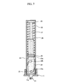
- Figure 7 illustrates the damping device 20 when the refrigerator door is closed.
- the configuration of the damping device 20 is previously explained in the above description in relation with Figure 4.
- the guide pins 23 are located at the lower ends of the spiral grooves 22a and 22b of the cam member 22.
- the support member 11 is coupled at the lower end of the damping member 20 so that the link connecting portion 21 is inserted through the support member 11 so as to protrude out of the support member 11.
- the casing 29 of the damping device 20 is seated in the cylindrical guide portion 11a having a certain height.
- the cam member 22, the piston 24 and the guide rod 27 are successively inserted inside the casing 29, seated in the support member 11.
- the spring 26 is interposed between the guide rod 27 and the piston 24.
- the cam member 22 has a hollow structure so that the piston 24 may be inserted therein.
- the piston 24 is linearly movable inside the cam member 22 as the guide pins 23 slide along the spiral grooves 22a and 22b of the cam member 22.
- the sealing member 25 is coupled around the piston 24 at a height that is sufficient to allow the sealing member 25 to be spaced apart from the upper end of the cam member 22 by a certain distance in the lowermost position of the piston 24. As stated above, the sealing member 25 is fixed to the piston 24 to support the spring 26 upon an extension of a contraction of the spring 26. In this way, the sealing member 25 serves not only as an oil sealing member, but also as a spring support member.
- the guide pins 23 are positioned at the lower ends of the spiral grooves 22a and 22b of the cam member 22.
- the piston 24, being connected to the guide pins 23 is in the lowermost position inside the hollow cam member 22.
- the cap member 28 connected to the guide rod 27 is positioned at an upper end of the casing 29 by the elasticity of the spring 26. That is, the spring 26 is in a completely extended state.
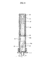
- Figure 8 illustrates the operation of the damping device 20 when the refrigerator door is opened.
- the link connecting portion 21 which was connected to the refrigerator door so as to protrude out of the support member 11
- the link members (not shown) connected to the refrigerator door and force the guide pins 23 to slide upward along the spiral grooves 22a and 22b of the cam member 22.
- the degree of upward movement of the guide pins 23 depends on the degree of opening of the refrigerator door. In a completely opened state, the guide pins 23 are positioned at the upper ends of the spiral grooves 22a and 22b.
- the present invention includes a feature in that the damping device 20 and the link device 10 connected thereto are mounted at the lower end of the front panel of the door.
- the damping device 20 may be mounted vertically inside the refrigerator door or the refrigerator housing within a narrow space, without requiring to be horizontally installed along the lower end of the housing 1. In this way, the overall structure of the link device 10 is simplified. Further, the device may be operable by only two link members.
- the damping device 20 In a closed state of the refrigerator door, the damping device 20 is in a state as shown in Figure 7 and the link device 10 connected thereto is in a state as shown in Figure 5.
- the first link member 12 and the second link member 15 are hingedly rotated away from each other.
- the link connecting portion 21 of the cam member 22 mounted in the door is rotated to cause the guide pins 23, fitted in the lower end of the piston 24 to slide upward along the spiral grooves 22a and 22b of the cam member 22.
- the piston 24 is moved upward so that the sealing member 25 fixed therearound compresses the spring 26 and the oil, while allowing the guide rod 27 to be inserted therein. Since a rotating angle of the link connecting portion 21 is variable according to an opening angle of the door, the position of the guide pins 23 as well as the compression of the spring 26 and the oil are correspondingly variable.
- the guide pins 23 are positioned at the upper ends of the spiral grooves 22a and 22b.
- the first and second link members 12 and 15 are rotated toward each other, and the link connecting portion 21 is rotated in an opposite direction to the opening direction of the door.
- the guide pins 23 are momentarily immobilized, and then slide downward to the lower ends of the spiral grooves 22a and 22b due to their gravity, the restoration force of the spring 26 and the repulsive force of the oil.
- the damping device of a refrigerator in accordance with the present invention since the damping device of a refrigerator in accordance with the present invention is reduced in size, and is vertically mountable by virtue of the reduced operating space thereof, the damping device may be installed inside a refrigerator door or refrigerator housing, rather than the bottom surface of the refrigerator. Further, the damping device may be mounted inside the lower end portion of a front panel of the refrigerator door, resulting in an ease of an exchange and repair thereof.
- the damping device may reduce the number of elements and the volume of a space required for the installation of a link device, resulting in enhancement in simplicity and easy assembly of the link device.
Landscapes
- Engineering & Computer Science (AREA)
- Chemical & Material Sciences (AREA)
- Combustion & Propulsion (AREA)
- Physics & Mathematics (AREA)
- Mechanical Engineering (AREA)
- Thermal Sciences (AREA)
- General Engineering & Computer Science (AREA)
- Refrigerator Housings (AREA)
Abstract
A refrigerator comprising a housing, a pair of doors, link devices, and damping
devices. Each of the damping devices includes a casing defining the appearance of
the damping device, a cam member, a piston, a sealing member fitted around the
piston, a spring, a guide rod, and a cap member connected to the guide rod so as to
be positioned inside the casing. Since the damping device of the present invention
is reducible in size and is vertically mountable by virtue of its reduced operating
space, it can be installed inside a refrigerator door or refrigerator housing rather
than the bottom surface of the refrigerator. Especially the damping device can be
mounted inside the lower end portion of a front panel of the refrigerator door
resulting in ease in exchange and repair thereof.
Description
- The present invention relates to a refrigerator including a closure mechanism for biasing a door of the refrigerator into a closed state, wherein the closure mechanism comprises a piston slideable within a housing against the force of a biasing member when the door is opened so that the door closes when released.
- In order to protect a refrigerator as well as any contents stored therein, they are generally provided with damping devices which provide the refrigerator doors with a smooth closing operation so as to absorb the shock generated upon closure of the doors. As such, oil filled damping devices have conventionally been used. This kind of damping device however has a problem in that a sealing member thereof can often become worn due to the rectilinear reciprocation of a rod provided in a link mechanism. Conventionally, the link mechanism is horizontally mounted at the bottom of a refrigerator. To achieve the rectilinear reciprocation of the rod, the link mechanism must disadvantageously have long links.
- Another problem of the conventional damping device is that the damping device requires a separate structure to be used to protect the oil damper as well as the links of the link mechanism.
- Furthermore, in a conventional damping structure for refrigerator doors such as stated above, the links of the link mechanism tend to bend due to external forces applied to the refrigerator door, and so there exists the need for a wide operating space to avoid interference of the links.
- In most cases, since the conventional damping device is generally located at the bottom of a refrigerator housing so that the conventional damping device connects the refrigerator housing to a refrigerator door by cooperating with the link mechanism, to repair the damping device, the refrigerator housing has to be laid down on the ground after any contents have been removed, resulting in extreme inconvenience in repair and exchange thereof.
- The present invention seeks to provide a system which overcomes or substantially alleviates the problems discussed above.
- A refrigerator according to the present invention is characterised in that the closure mechanism comprises cooperating cam members that translates rotational movement of the door into linear movement of the piston.
- Advantageously, the closure mechanism comprises a shaft mounted in the housing, one end of the shaft protruding from the housing being connected via a linkage to the door so that the shaft rotates in response to movement of the door between its open and closed state.
- Preferably, the cooperating cam members comprise a generally helically formed cam path on the shaft and a cam follower on the piston so that the cam follower follows the cam path when the shaft rotates to cause the piston to slide linearly within the housing.
- In a preferred embodiment, the biasing means is a spring..
- Advantageously, the piston has a hole therein to receive an elongate guide member fixed to the housing, the guide member sliding within the piston during movement of the piston when the door is opened and closed
- Therefore, an aspect of the present invention may provide a refrigerator comprising a damping device of a refrigerator door which is mountable even in a narrow space by virtue of a reduced operating space of the damping device, and a simplified link device, which enables the damping device to be mounted to the refrigerator door without interference of other members.
- Another aspect of the invention may provide a refrigerator comprising a damping device, which is designed to be mounted in a separate space defined in a refrigerator door, resulting in simplicity in repair and exchange thereof.
- Embodiments of the present invention will now be described, by way of example only, with reference to the accompanying drawings, in which:
- Figure 1 is a perspective view illustrating the mounting position of a damping device in a refrigerator in accordance with the present invention;
- Figure 2 is an exploded perspective view illustrating a link mechanism to which the damping device of a refrigerator is coupled;
- Figure 3 is a perspective view illustrating an assembled state of the link mechanism;
- Figure 4 is an exploded perspective view illustrating the structure of the damping device;
- Figure 5 is a front view illustrating the structure of the link mechanism in a state in which a refrigerator door is closed;
- Figure 6 is a front view illustrating the structure of the link mechanism in a state in which the refrigerator door is opened;
- Figure 7 is a sectional view illustrating the operation of the damping device in a state in which the refrigerator door is closed; and
- Figure 8 is a sectional view illustrating the operation of the damping device in a state in which the refrigerator door is opened.
-
- Referring now to the drawings, there is shown in Figure 1 a refrigerator comprising a rectangular housing 1 that is open at a front side thereof, and
doors door link mechanism 10 provided at an upper or lower end thereof.Damping devices 20 which ensure the smooth opening and closing operations of thedoors link mechanism 10. Consequently, thedamping devices 20 prevent shock from being applied to the housing 1. In "side by side type refrigerators", equal numbers ofdamping devices 20 are provided inside each of thedoors - The interior of the refrigerator is divided into a left freezing chamber and a right refrigerating chamber which are both designated by reference numeral 2. A plurality of
shelves 5 and storage containers 6 to store foods are provided inside the freezing and refrigerating chambers 2. Shelves 7 to store beverages or small containers are provided on the inner surfaces of thedoors - As shown in Figure 2, the
damping devices 20 are provided inside thedoors damping device 20 is mounted in a separate mounting space defined in therespective doors respective doors doors damping device 20 of the present invention encounters substantially fewer spatial problems than a conventional link mechanism, which requires a wide horizontal space. - Such a
damping device 20 includes alink connecting portion 21 formed at one end which is inserted through acylindrical guide portion 11a provided on a rectangular plate-shaped support member 11 so as to protrude out of thesupport member 11 through a centre opening 11b. Thesupport member 11 is further provided with a plurality ofbolt fastening holes 11c to enable the fastening of thesupport member 11 to thedoor - A
first link member 12 is coupled to thelink connecting portion 21 which protrudes out of thesupport member 11. Thefirst link member 12 is bar shaped and has a first hole formed at one end thereof to be used in the coupling of thelink connecting portion 21 and a second hole at the other end thereof to be used in the coupling of asecond link member 15. - The
second link member 15 is bar shaped similar to thefirst link member 12. However, thesecond link member 15 is longer than thefirst link member 12. By usingfasteners second link member 15 may be coupled to thefirst link member 12, and the other end of thesecond link member 15 coupled to ahinge member 17. The first andsecond link members - In this embodiment, the
hinge member 17 is a plate, but the shape is not limited thereto. As such, thehinge member 17 may have other appropriate shapes in consideration of the coupling relationship between thedoor hinge member 17 is fixed to the refrigerator housing 1 and the other end is fixed to therefrigerator door hinge shaft 18. Thehinge member 17 has an area that is sufficient to support the load of the refrigerator door. - The
hinge member 17 is formed with a threadedprotrusion 17a to be used in the coupling of thesecond link member 15 and an opening 17b to enable the coupling of a hingeshaft coupling member 19. The hingeshaft coupling member 19 is fastened to the end of the bottom surface of thedoor hinge member 17 further includes a plurality of threadedholes 17c to allow thehinge member 17 to be firmly fastened to both therefrigerator doors - The
link mechanism 10 comprising the link members is coupled to thedamping device 20 as shown in Figure 3. Thedamping device 20 is mounted inside thedoor 4 and thesupport member 11 is bolted to the lower end of thedoor 4 so that thelink connecting portion 21 of thedamping device 20 protrudes out of thesupport member 11 through the centre opening 11b. The first hole of thefirst link member 12 is fitted to thelink connecting portion 21 and held in place by a nut. - The
second link member 15 is bolted to thefirst link member 12. The twolink members doors second link members second link members second link member 15 is fixedly coupled to thehinge member 17 wherein one of the holes thereof is fitted around theprotrusion 17a of thehinge member 17 and held in place with a nut. - The
hinge shaft 18 is fitted through the opening 17b of thehinge member 17. Thehinge shaft 18 is further fitted in a hinge shaft opening 19a of the hingeshaft coupling member 19 which would have been previously fastened to the end of the bottom surface of the refrigerator door so as to attach thehinge member 17 to the door. The threadedholes 17c of thehinge member 17 are bolted to corresponding holes formed at the refrigerator housing 1 so as to allow thehinge member 17 to be firmly fastened to the refrigerator housing 1. The hingeshaft coupling member 19 having the hinge shaft opening 19a which is provided at the end of the bottom surface of the refrigerator door, simplifies the coupling of thehinge member 17 to the refrigerator door. - Referring to Figure 4, the
damping device 20 comprises acam member 22 to be inserted into thesupport member 11. Acasing 29 is threaded into thecylindrical guide portion 11a of thesupport member 11. Thelink connecting portion 21 of thecam member 22, having an elliptical shape, is inserted through the centre opening 11b of thesupport member 11. As a result, the motion of the link members is transmitted to thecam member 22 to induce the operation of the dampingdevice 20 in correspondence to the opening and closing operations of the refrigerator door. - The
cam member 22 is inserted into thesupport member 11 through thelink connecting portion 21 provided at one end thereof. The diameter of thecam member 22 is larger than that of thelink connection portion 21.Spiral grooves cam member 22. Both ends of therespective spiral grooves respective spiral grooves - Rotatably fitted guide pins 23 extend into the
spiral grooves spiral grooves respective spiral grooves spiral grooves - Each of the guide pins 23 has a threaded
portion 23a at one end to ensure an easy assembly as well as a pin head at the other end. When apiston 24 is inserted in thecam member 22, the threadedportions 23a of the guide pins 23 are screwed intoholes 24a that are formed at the lower end region of apiston 24 by passing the threadedportions 23a of the guide pins 23 through thespiral grooves cam member 22. - A sealing
member 25 is provided around the circumference of thepiston 24. The sealingmember 25 seals oil that is charged around thepiston 24 between the sealingmember 25 and acap member 28. Thecap member 28 is located at the distal end of aguide rod 27. The sealingmember 25 is formed with a small through-hole 25a to allow the oil to be supplied to thecam member 22 so as to achieve a smooth operation of thecam member 22 and to provide a damping effect. The sealingmember 25 also supports aspring 26 which is fitted around thepiston 24. To this end, the sealingmember 25 is fixedly coupled around thepiston 24 so as not to move along thepiston 24. - The
piston 24 is hollow and theguide rod 27 may be inserted into the distal end and allowed to move vertically. The insertion of theguide rod 27 into thepiston 24 is possible as theguide rod 27 has a smaller diameter than an inner diameter of thepiston 24. Thecap member 28 provided at the distal end of theguide rod 27 has a disc shape and contacts with an upper end of thepiston 24 according to the motion of theguide rod 27. - The cross sectional shapes of the
guide rod 27 and thecap member 28 are not perfectly circular and may instead be partially cut-away circles. This, together with corresponding receiving portions in thepiston 24 andcasing 29 allow theguide rod 27 to linearly move inside thepiston 24 without rotating when thecam member 22 is rotated upon an opening of the refrigerator door. Of course, the cross sectional shapes of theguide rod 27 and thepiston 24 are not limited to partially cut-away circles and may be freely selected from shapes such as square, so long as the shape of theguide rod 27 and thepiston 24 prevents rotation. - That is the
guide rod 27 and thepiston 24 are designed to only linearly move inside thecasing 29. Meanwhile, thecam member 22 is designed to rotate around thepiston 24. - The
spring 26 interposed between theguide rod 27 and thepiston 24 has a length that is equal to the sum of the length of theguide rod 27 and the length from the upper end of thepiston 24 to the sealingmember 25 that is fixed around thepiston 24. As thecap member 28 vertically moves according to linear motion of theguide rod 27 coupled thereto, thespring 26 contracts or extends. - The interior of the
casing 29 is charged with the oil in the region of thecasing 29 that extends from the sealingmember 25 to thecap member 28 when thecap member 28 is coupled to theguide rod 27. Part of the oil is supplied into thecam member 22 along thespiral grooves hole 25a formed at the sealingmember 25, resulting in smooth controlled driving of thecam member 22. One end of thecasing 29 is blocked and the other end is formed with a threadedportion 29a to allow thecasing 29 to be securely threaded to thecylindrical guide portion 11 a of thesupport member 11. - Figure 5 illustrates the structure of the
link device 10 when therefrigerator door 4 is closed. In this state, thefirst link member 12 and thesecond link member 15 of thelink device 10 are angled with respect to each other rather than completely overlapped. Such an arrangement is effective to support the load of the refrigerator door in rotation as well as in a stationary state. - Figure 6 illustrates the structure of the
link device 10 when therefrigerator door 4 is opened to the right by an angle of 90 degrees compared to Figure 5. In general, the refrigerator door is openable through an angle of approximately 135 degrees. - As the
refrigerator door 4 is opened, thesupport member 11 that is fixed to thedoor 4 is displaced to the right and rotated along with thedoor 4 and accordingly, a joint portion between thefirst link member 12 coupled to thesupport member 11 and thesecond link member 15 is displaced to the right. Thereby, thesecond link member 15 is hingedly rotated in a rotating direction of thedoor 4. - Upon opening the
door 4, thelink connecting portion 21, which was rotatably mounted to thedoor 4, is rotated. Such a rotation of thelink connecting portion 21 is converted into linear motion of thepiston 24 by thecam member 22. - Figure 7 illustrates the damping
device 20 when the refrigerator door is closed. The configuration of the dampingdevice 20 is previously explained in the above description in relation with Figure 4. In a closed state of the door, the guide pins 23 are located at the lower ends of thespiral grooves cam member 22. - The
support member 11 is coupled at the lower end of the dampingmember 20 so that thelink connecting portion 21 is inserted through thesupport member 11 so as to protrude out of thesupport member 11. In this case, thecasing 29 of the dampingdevice 20 is seated in thecylindrical guide portion 11a having a certain height. - The
cam member 22, thepiston 24 and theguide rod 27 are successively inserted inside thecasing 29, seated in thesupport member 11. Thespring 26 is interposed between theguide rod 27 and thepiston 24. Thecam member 22 has a hollow structure so that thepiston 24 may be inserted therein. Thepiston 24 is linearly movable inside thecam member 22 as the guide pins 23 slide along thespiral grooves cam member 22. - The sealing
member 25 is coupled around thepiston 24 at a height that is sufficient to allow the sealingmember 25 to be spaced apart from the upper end of thecam member 22 by a certain distance in the lowermost position of thepiston 24. As stated above, the sealingmember 25 is fixed to thepiston 24 to support thespring 26 upon an extension of a contraction of thespring 26. In this way, the sealingmember 25 serves not only as an oil sealing member, but also as a spring support member. - In a closed state, the guide pins 23 are positioned at the lower ends of the
spiral grooves cam member 22. Thus, thepiston 24, being connected to the guide pins 23, is in the lowermost position inside thehollow cam member 22. In this case, since no pressure is applied to theguide rod 27, thecap member 28 connected to theguide rod 27 is positioned at an upper end of thecasing 29 by the elasticity of thespring 26. That is, thespring 26 is in a completely extended state. - Figure 8 illustrates the operation of the damping
device 20 when the refrigerator door is opened. Where the refrigerator door is opened by receiving an external force, thelink connecting portion 21 which was connected to the refrigerator door so as to protrude out of thesupport member 11, is rotated by the link members (not shown) connected to the refrigerator door and force the guide pins 23 to slide upward along thespiral grooves cam member 22. The degree of upward movement of the guide pins 23 depends on the degree of opening of the refrigerator door. In a completely opened state, the guide pins 23 are positioned at the upper ends of thespiral grooves - As a result, the
piston 24, which was coupled to the guide pins 23 so as to vertically move inside thecam member 22, compresses the oil and thespring 26 by making use of the sealingmember 25 sealably coupled around thepiston 24. Since the oil and thespring 26 have a tendency to restore to their original states due to their shock absorbing and elastic properties, the door may be smoothly closed, and may automatically close when the door is opened within a range that is not more than a predetermined angle. - When the refrigerator door is closed, a force, applied to the guide pins 23, is released. Thus, the guide pins 23 slide downward along the
spiral grooves spring 26. As a result, the guide pins 23 become seated in the lower ends of thespiral grooves elastic spring 26 and the oil charged in the lower part of thecasing 29. As a further result, since the guide pins 23 slowly slide downward along thespiral grooves spring 26 and a repulsive force of the oil against the volume constriction thereof, thelink connecting portion 21 connected thereto is accordingly slowly rotated and the refrigerator door is smoothly closed. - Now, the operation and effects of the preferred embodiment of the present invention will be explained in detail. The present invention includes a feature in that the damping
device 20 and thelink device 10 connected thereto are mounted at the lower end of the front panel of the door. - Different from the conventional damping device and by virtue of a reduced operating space, the damping
device 20 may be mounted vertically inside the refrigerator door or the refrigerator housing within a narrow space, without requiring to be horizontally installed along the lower end of the housing 1. In this way, the overall structure of thelink device 10 is simplified. Further, the device may be operable by only two link members. - Now, the rotation of the damping
device 20 using thehinge member 17 will be explained in detail. - In a closed state of the refrigerator door, the damping
device 20 is in a state as shown in Figure 7 and thelink device 10 connected thereto is in a state as shown in Figure 5. If an external force causes the door to be opened, thefirst link member 12 and thesecond link member 15 are hingedly rotated away from each other. Thus thelink connecting portion 21 of thecam member 22 mounted in the door is rotated to cause the guide pins 23, fitted in the lower end of thepiston 24 to slide upward along thespiral grooves cam member 22. As a result, thepiston 24 is moved upward so that the sealingmember 25 fixed therearound compresses thespring 26 and the oil, while allowing theguide rod 27 to be inserted therein. Since a rotating angle of thelink connecting portion 21 is variable according to an opening angle of the door, the position of the guide pins 23 as well as the compression of thespring 26 and the oil are correspondingly variable. - When the door begins to close again, the guide pins 23 are positioned at the upper ends of the
spiral grooves second link members link connecting portion 21 is rotated in an opposite direction to the opening direction of the door. At the moment when thelink connecting portion 21 begins to rotate, the guide pins 23 are momentarily immobilized, and then slide downward to the lower ends of thespiral grooves spring 26 and the repulsive force of the oil. - Even if a relatively strong external force closes the door, the
spring 26 and the oil returned slowly to their original states, resulting in damping effect. - As is apparent from the above description, since the damping device of a refrigerator in accordance with the present invention is reduced in size, and is vertically mountable by virtue of the reduced operating space thereof, the damping device may be installed inside a refrigerator door or refrigerator housing, rather than the bottom surface of the refrigerator. Further, the damping device may be mounted inside the lower end portion of a front panel of the refrigerator door, resulting in an ease of an exchange and repair thereof.
- Further, according to the present invention, the damping device may reduce the number of elements and the volume of a space required for the installation of a link device, resulting in enhancement in simplicity and easy assembly of the link device.
- Although a few embodiments of the present invention have been shown and described, it will be appreciated by those skilled in the art that changes may be made in these embodiments without departing from the principles of the invention, the scope of which is defined in the claims and their equivalents and the foregoing description should be regarded as a description of a preferred embodiment only.
Claims (27)
- A refrigerator including a closure mechanism for biasing a door of the refrigerator into a closed state, wherein the closure mechanism comprises a piston slideable within a housing against the force of a biasing member when the door is opened so that the door closes when released, characterised in that the closure mechanism comprises cooperating cam members that translates rotational movement of the door into linear movement of the piston.
- A refrigerator according to claim 1, wherein the closure mechanism comprises a shaft mounted in the housing, one end of the shaft protruding from the housing being connected via a linkage to the door so that the shaft rotates in response to movement of the door between its open and closed state.
- A refrigerator according to claim 2, wherein the cooperating cam members comprise a generally helically formed cam path on the shaft and a cam follower on the piston so that the cam follower follows the cam path when the shaft rotates to cause the piston to slide linearly within the housing.
- A refrigerator according to claim 1 or claim 2, wherein the biasing means is a spring.
- A refrigerator according to any preceding claim, wherein the piston has a hole therein to receive an elongate guide member fixed to the housing, the guide member sliding within the piston during movement of the piston when the door is opened and closed.
- A refrigerator including a housing and a pair of doors that are coupled to the housing in a hingedly rotatable manner, the refrigerator comprising sets of link devices to respectively transmit a rotating force of each of the doors relative to the housing, a damper associated with each of the doors coupled to the respective link devices to absorb a shock to each of the doors and to allow each of the doors to be automatically closed.
- The refrigerator according to claim 6 wherein each damper includes a substantially cylindrical casing, a cam member coupled to each of the link devices so as to convert the rotating motion of the associated one of the doors into linear motion, a piston coupled to the cam member inside the casing to move linearly and a spring anchored to the casing and oil charged inside the casing to dampen the liner motion of the piston.
- The refrigerator according to claim 7 wherein the damper is mounted vertically inside the door.
- The refrigerator according to claim 7 wherein the cam member of the damper comprises a substantially hollow shaft having spiral grooves wherein the piston is coupled to the cam member to linearly move along the spiral grooves and the cam member converts the rotating motion of the door transmitted through an associated one of the link devices to the linear motion of the piston.
- The refrigerator according to claim 7 further comprising link connection portions to couple the cam members to the respective link devices wherein each cam member is positioned inside each cylindrical casing so that the link connecting portion is provided at one end of each cylindrical casing and protrudes outwardly to allow the link device to be rotatably fitted therearound.
- The refrigerator according to claim 10 wherein the damping device further includes a sealing member which is fixed around the piston to seal the oil charged around the piston inserted inside the casing.
- The refrigerator according to claim 10 wherein the cam member and the piston are coupled to each other by guide pins so that the piston is linearly movable within a range of the spiral grooves formed at the cam member.
- The refrigerator according to claim 12 wherein the guide pins are located close to a lower end of the cam member in a closed state of the door and slide upward along the spiral grooves toward an upper end of the cam member by receiving an external force when the door is opened so as to allow the oil to be compressed by a sealing member.
- The refrigerator according to claim 13 wherein the guide pins allow the door to be smoothly and/or automatically closed as they are returned toward the lower end of the cam member by making use of a repulsive force of the spring and/or the oil.
- A refrigerator comprising a housing and a pair of doors coupled to the housing in a hingedly rotatable manner the refrigerator further comprising damping devices provided at the doors or the housing and link devices to connect the housing and the respective doors and to transmit a rotating force of the doors to the damping devices.
- The refrigerator according to claim 15 wherein each of the link devices includes a first link member and a second link member.
- The refrigerator according to claim 16 wherein each of the first and second link members has rotatably connectable joint portions at both ends thereof.
- The refrigerator according to claim 16 wherein the first and second link members partially overlap each other while forming a small angle therebetween in a closed state of an associated one of the doors, whereas they are spaced apart from each other by a certain large angle when the door is opened.
- The refrigerator according to claim 17 wherein fasteners to rotatably connect the first and second link members to each other are coupled to the respective joint portions.
- The refrigerator according to claim 15 wherein each link device is adjacent to a central axis of rotation of an associated one of the doors.
- The refrigerator according to claim 15 wherein each link device includes a hinge member and a hinge shaft, wherein one end of the hinge member is fixed to the housing and the other end of the hinge member is coupled to the associated one of the doors by the hinge shaft so as to secure rotation of the door.
- The refrigerator according to claim 7 wherein the damper is mounted vertically inside one of the doors.
- The damping device to dampen to absorb shock applied to a refrigerator door and to automatically close the refrigerator door comprising a hinge to rotatably connect the door to the refrigerator so as to allow the door to rotate from a first position in which the door closes the refrigerator to a second position in which the refrigerator is open, a damper including a cylindrical casing, a cam to translate the rotational movement of the door to linear movement, a piston coupled to the cam to move linearly in accordance with the translated rotational movement and a spring anchored to the casing to oppose the movement of the piston in one direction and aid the movement of the piston in the other direction and a link system to connect the hinge with the damper so as to actuate the damper.
- The damping device according to claim 23 wherein the damper is coupled to the door via a support member having a cylindrical guide portion into which the piston is inserted and a circular centre opening.
- The damping device according to claim 24 further comprising a link connecting portion to integrally protrude from the end of the cam, the link connecting portion having a cylindrical section to extend through the circular centre opening of the support member and a rectangular section to cooperate with the link system.
- The damping device according to claim 24 wherein the link system comprises a first link member having a rectangular hole to cooperate with the rectangular section of the link connecting portion at a first end thereof and a second link member to be coupled to a second end of the first link member at a first end thereof and to be coupled to the hinge at a second end thereof.
- The damping device according to claim 24 wherein the second link member is longer than the first link member.
Applications Claiming Priority (2)
| Application Number | Priority Date | Filing Date | Title |
|---|---|---|---|
| KR1020040036260A KR20050111094A (en) | 2004-05-21 | 2004-05-21 | Refrigerator |
| KR2004036260 | 2004-05-21 |
Publications (1)
| Publication Number | Publication Date |
|---|---|
| EP1598512A2 true EP1598512A2 (en) | 2005-11-23 |
Family
ID=34940433
Family Applications (1)
| Application Number | Title | Priority Date | Filing Date |
|---|---|---|---|
| EP05250645A Withdrawn EP1598512A2 (en) | 2004-05-21 | 2005-02-04 | Refrigerator |
Country Status (5)
| Country | Link |
|---|---|
| US (1) | US20050258724A1 (en) |
| EP (1) | EP1598512A2 (en) |
| KR (1) | KR20050111094A (en) |
| CN (1) | CN100453937C (en) |
| AU (1) | AU2005201545B2 (en) |
Cited By (6)
| Publication number | Priority date | Publication date | Assignee | Title |
|---|---|---|---|---|
| EP1903287A2 (en) | 2006-09-21 | 2008-03-26 | LG Electronics Inc. | Refrigerator |
| EP2522798A3 (en) * | 2011-05-12 | 2015-03-25 | BSH Hausgeräte GmbH | Household cooler with a self-closing hinge assembly |
| EP2522939A3 (en) * | 2011-05-12 | 2018-03-21 | BSH Hausgeräte GmbH | Household cooler with a hinge assembly |
| EP2522940A3 (en) * | 2011-05-12 | 2018-04-11 | BSH Hausgeräte GmbH | Household cooler with a self-closing hinge assembly |
| CN114348443A (en) * | 2021-12-02 | 2022-04-15 | 浙江拉斯贝姆餐饮设备有限公司 | Refrigerator door transfer device capable of automatically stacking |
| CN114630534A (en) * | 2022-04-28 | 2022-06-14 | 朝阳市加华电子有限公司 | Anti-seismic device of intelligent power management equipment of boats and ships |
Families Citing this family (35)
| Publication number | Priority date | Publication date | Assignee | Title |
|---|---|---|---|---|
| KR101235195B1 (en) * | 2006-01-23 | 2013-02-20 | 삼성전자주식회사 | Refrigerator |
| KR100789666B1 (en) * | 2006-10-23 | 2008-01-02 | 주식회사 아이원이노텍 | Adjustable height link device for refrigerator door |
| KR101424554B1 (en) * | 2007-01-23 | 2014-07-31 | 삼성전자 주식회사 | A bidirectional door unit and a refrigerator including the same |
| JP4934534B2 (en) * | 2007-07-26 | 2012-05-16 | 三洋電機株式会社 | Storage |
| DE102008034809A1 (en) * | 2008-07-24 | 2010-01-28 | Suspa Holding Gmbh | Drive device for refrigerator doors |
| US8267492B2 (en) * | 2009-05-07 | 2012-09-18 | Whirlpool Corporation | Method of routing utilities through an articulated hinge |
| US8186781B2 (en) * | 2009-05-07 | 2012-05-29 | Whirlpool Corporation | Articulated hinges using non-circular gears |
| KR20100122155A (en) | 2009-05-12 | 2010-11-22 | 엘지전자 주식회사 | Refrigerator |
| KR101307681B1 (en) * | 2009-06-03 | 2013-09-12 | 엘지전자 주식회사 | Refrigerator |
| KR101307735B1 (en) | 2009-06-03 | 2013-09-11 | 엘지전자 주식회사 | Refrigerator |
| KR101307690B1 (en) * | 2009-07-28 | 2013-09-12 | 엘지전자 주식회사 | Refrigerator |
| KR101302757B1 (en) | 2009-07-28 | 2013-09-02 | 엘지전자 주식회사 | Refrigerator |
| CN102116554A (en) | 2010-01-04 | 2011-07-06 | Lg电子株式会社 | Refrigerator |
| EP3205958B1 (en) | 2010-02-01 | 2019-11-13 | LG Electronics Inc. | Refrigerator |
| BR112012006215B1 (en) | 2010-02-01 | 2021-01-26 | Lg Electronics Inc. | cooler |
| IT1400022B1 (en) * | 2010-05-11 | 2013-05-09 | Ind Casearia Silvio Belladelli S R L | DOOR CLOSER DEVICE |
| MX337697B (en) | 2010-06-22 | 2016-03-14 | Lg Electronics Inc | Refrigerator and method of manufacturing the same. |
| KR101704817B1 (en) | 2010-08-20 | 2017-02-08 | 엘지전자 주식회사 | Refirgerator |
| EP4209737A1 (en) | 2011-08-05 | 2023-07-12 | LG Electronics Inc. | Refrigerator with inner door |
| KR101343915B1 (en) * | 2012-02-02 | 2013-12-20 | 동우정밀(주) | A single hinge damping device for a door of electric home appliances |
| AU2013245561B2 (en) | 2012-10-25 | 2016-05-26 | Lg Electronics Inc. | Laundry treatment machine with lid hinge having cam members |
| DE102014106876A1 (en) * | 2014-05-15 | 2015-11-19 | Hettich-Oni Gmbh & Co. Kg | Bearing arrangement for a door |
| KR102306955B1 (en) * | 2015-02-23 | 2021-10-01 | 삼성전자주식회사 | Refrigerator |
| CN105674672B (en) * | 2016-03-15 | 2018-09-04 | 青岛海尔股份有限公司 | A kind of refrigerator automatic telescopic vertical beam and side by side combination refrigerator |
| DE102016224394A1 (en) * | 2016-12-07 | 2018-06-07 | BSH Hausgeräte GmbH | Domestic refrigerating appliance with non-destructively detachable roller assembly at the bottom of a housing |
| US11859434B1 (en) * | 2017-03-01 | 2024-01-02 | Mansfield Engineered Components, LLC | Dampened hinge for a refrigerator door or other door |
| CN108120202A (en) * | 2017-12-27 | 2018-06-05 | 莱州澳德仕制冷科技有限公司 | A kind of refrigerator glazed door |
| IT201800005039A1 (en) * | 2018-05-03 | 2019-11-03 | HINGE DEVICE FOR REFRIGERATORS AND FURNITURE | |
| KR102731800B1 (en) * | 2019-04-03 | 2024-11-20 | 엘지전자 주식회사 | Refrigerator |
| CN113811108B (en) * | 2020-06-11 | 2023-03-21 | 北京机械设备研究所 | Hinge structure of cabinet door and opening and closing method of cabinet door |
| CN111649519B (en) * | 2020-07-09 | 2024-08-16 | 长虹美菱股份有限公司 | Refrigerator with iced device system |
| EP3960975A1 (en) * | 2020-08-27 | 2022-03-02 | F. Hoffmann-La Roche AG | Door hinge for a laboratory instrument door |
| CN115839583B (en) * | 2021-09-18 | 2026-04-28 | 海信冰箱有限公司 | refrigerator |
| CN116411755A (en) * | 2022-01-05 | 2023-07-11 | 青岛海尔电冰箱有限公司 | Hinge and refrigeration device with the hinge |
| WO2024056076A1 (en) * | 2022-09-16 | 2024-03-21 | 青岛海尔电冰箱有限公司 | Refrigerator |
Family Cites Families (9)
| Publication number | Priority date | Publication date | Assignee | Title |
|---|---|---|---|---|
| DE29611392U1 (en) * | 1996-07-01 | 1996-08-29 | Hermann Forster Ag, Arbon | Hinge for refrigerators and freezers |
| JP3150633B2 (en) * | 1996-11-05 | 2001-03-26 | 大阪金具株式会社 | Automatic door closing device |
| US5931554A (en) * | 1997-08-29 | 1999-08-03 | General Electric Company | Refrigerator door stop |
| US6036292A (en) * | 1998-06-23 | 2000-03-14 | Maytag Corporation | Refrigerator cabinet incorporating a plastic kickface |
| DE20114654U1 (en) * | 2001-09-05 | 2003-02-06 | Liebherr-Hausgeräte GmbH, 88416 Ochsenhausen | Fridge and freezer |
| US6684453B2 (en) * | 2002-06-14 | 2004-02-03 | Fu Luong Hi-Tech Co., Ltd. | Hinge assembly capable of damping door movement |
| JP3983654B2 (en) * | 2002-11-27 | 2007-09-26 | 株式会社ニフコ | damper |
| DE20308223U1 (en) * | 2003-05-22 | 2003-08-07 | Julius Blum Ges.m.b.H., Höchst | Damped support for hinge of furniture door has a hinged lever linked to a telescopic damping lever running over a profiled track |
| US7155776B2 (en) * | 2003-06-10 | 2007-01-02 | I-One Innotech Co., Ltd. | Multipurpose hinge apparatus having automatic return function |
-
2004
- 2004-05-21 KR KR1020040036260A patent/KR20050111094A/en not_active Withdrawn
-
2005
- 2005-01-31 CN CNB2005100061839A patent/CN100453937C/en not_active Expired - Fee Related
- 2005-02-04 EP EP05250645A patent/EP1598512A2/en not_active Withdrawn
- 2005-03-28 US US11/090,276 patent/US20050258724A1/en not_active Abandoned
- 2005-04-13 AU AU2005201545A patent/AU2005201545B2/en not_active Ceased
Cited By (9)
| Publication number | Priority date | Publication date | Assignee | Title |
|---|---|---|---|---|
| EP1903287A2 (en) | 2006-09-21 | 2008-03-26 | LG Electronics Inc. | Refrigerator |
| EP1903287A3 (en) * | 2006-09-21 | 2012-06-13 | LG Electronics Inc. | Refrigerator |
| EP2522798A3 (en) * | 2011-05-12 | 2015-03-25 | BSH Hausgeräte GmbH | Household cooler with a self-closing hinge assembly |
| EP2522939A3 (en) * | 2011-05-12 | 2018-03-21 | BSH Hausgeräte GmbH | Household cooler with a hinge assembly |
| EP2522940A3 (en) * | 2011-05-12 | 2018-04-11 | BSH Hausgeräte GmbH | Household cooler with a self-closing hinge assembly |
| CN114348443A (en) * | 2021-12-02 | 2022-04-15 | 浙江拉斯贝姆餐饮设备有限公司 | Refrigerator door transfer device capable of automatically stacking |
| CN114348443B (en) * | 2021-12-02 | 2023-11-03 | 浙江拉斯贝姆餐饮设备有限公司 | Refrigerator door transfer device capable of automatically stacking |
| CN114630534A (en) * | 2022-04-28 | 2022-06-14 | 朝阳市加华电子有限公司 | Anti-seismic device of intelligent power management equipment of boats and ships |
| CN114630534B (en) * | 2022-04-28 | 2024-02-13 | 朝阳市加华电子有限公司 | Anti-seismic device of ship intelligent power management equipment |
Also Published As
| Publication number | Publication date |
|---|---|
| CN1699898A (en) | 2005-11-23 |
| US20050258724A1 (en) | 2005-11-24 |
| CN100453937C (en) | 2009-01-21 |
| AU2005201545A1 (en) | 2005-12-08 |
| AU2005201545B2 (en) | 2007-02-22 |
| KR20050111094A (en) | 2005-11-24 |
Similar Documents
| Publication | Publication Date | Title |
|---|---|---|
| EP1598512A2 (en) | Refrigerator | |
| RU2386773C2 (en) | Hinged device | |
| KR101603462B1 (en) | Furniture hinge | |
| US6154924A (en) | Door closer unit | |
| US7360278B2 (en) | Home-bar door opening/closing device for refrigerator | |
| US8844097B2 (en) | Soft opening for a hinge | |
| KR101343915B1 (en) | A single hinge damping device for a door of electric home appliances | |
| KR102070695B1 (en) | A multi-link hinge for refrigerator | |
| KR20130041273A (en) | Furniture damper | |
| KR20080108491A (en) | Furniture hinge | |
| US20060255045A1 (en) | Hinge device for storage cases and storage case having the same | |
| KR20200096533A (en) | Hinges, storage units, and refrigerators | |
| EP3366164B1 (en) | Refrigerated cabinet with one or more automatically closing doors | |
| EP4450745A1 (en) | Refrigerator | |
| KR102476694B1 (en) | Refrigerator | |
| US20050262868A1 (en) | Automatic door opening and closing apparatus and refrigerator having the same | |
| KR102712105B1 (en) | Refrigerator | |
| KR100789666B1 (en) | Adjustable height link device for refrigerator door | |
| KR100457981B1 (en) | Device for opening and shutting of refrigerator door | |
| CN218234774U (en) | Embedded refrigerator hinge and refrigerator | |
| US20240426151A1 (en) | Hinge assembly and opening and closing device | |
| EP4682451A1 (en) | Refrigerator | |
| KR200209589Y1 (en) | Vertical type door closer | |
| KR200222837Y1 (en) | The shock absorber of refrigerator | |
| KR100548814B1 (en) | Hinge Assembly for Door Opening and Closing of Kimchi Storage |
Legal Events
| Date | Code | Title | Description |
|---|---|---|---|
| PUAI | Public reference made under article 153(3) epc to a published international application that has entered the european phase |
Free format text: ORIGINAL CODE: 0009012 |
|
| AK | Designated contracting states |
Kind code of ref document: A2 Designated state(s): AT BE BG CH CY CZ DE DK EE ES FI FR GB GR HU IE IS IT LI LT LU MC NL PL PT RO SE SI SK TR |
|
| AX | Request for extension of the european patent |
Extension state: AL BA HR LV MK YU |
|
| STAA | Information on the status of an ep patent application or granted ep patent |
Free format text: STATUS: THE APPLICATION IS DEEMED TO BE WITHDRAWN |
|
| 18D | Application deemed to be withdrawn |
Effective date: 20090901 |