EP1598132A1 - Edge replacement tip and cutting tool using the same - Google Patents
Edge replacement tip and cutting tool using the same Download PDFInfo
- Publication number
- EP1598132A1 EP1598132A1 EP04710549A EP04710549A EP1598132A1 EP 1598132 A1 EP1598132 A1 EP 1598132A1 EP 04710549 A EP04710549 A EP 04710549A EP 04710549 A EP04710549 A EP 04710549A EP 1598132 A1 EP1598132 A1 EP 1598132A1
- Authority
- EP
- European Patent Office
- Prior art keywords
- insert
- protrusions
- shaped
- holder
- cutting
- Prior art date
- Legal status (The legal status is an assumption and is not a legal conclusion. Google has not performed a legal analysis and makes no representation as to the accuracy of the status listed.)
- Granted
Links
Images

Classifications
-
- B—PERFORMING OPERATIONS; TRANSPORTING
- B23—MACHINE TOOLS; METAL-WORKING NOT OTHERWISE PROVIDED FOR
- B23B—TURNING; BORING
- B23B27/00—Tools for turning or boring machines; Tools of a similar kind in general; Accessories therefor
- B23B27/14—Cutting tools of which the bits or tips or cutting inserts are of special material
- B23B27/16—Cutting tools of which the bits or tips or cutting inserts are of special material with exchangeable cutting bits or cutting inserts, e.g. able to be clamped
-
- B—PERFORMING OPERATIONS; TRANSPORTING
- B23—MACHINE TOOLS; METAL-WORKING NOT OTHERWISE PROVIDED FOR
- B23B—TURNING; BORING
- B23B27/00—Tools for turning or boring machines; Tools of a similar kind in general; Accessories therefor
- B23B27/14—Cutting tools of which the bits or tips or cutting inserts are of special material
- B23B27/16—Cutting tools of which the bits or tips or cutting inserts are of special material with exchangeable cutting bits or cutting inserts, e.g. able to be clamped
- B23B27/1644—Cutting tools of which the bits or tips or cutting inserts are of special material with exchangeable cutting bits or cutting inserts, e.g. able to be clamped with plate-like cutting inserts of special shape clamped by a clamping member acting almost perpendicularly on the chip-forming plane and at the same time upon the wall of a hole in the cutting insert
-
- B—PERFORMING OPERATIONS; TRANSPORTING
- B23—MACHINE TOOLS; METAL-WORKING NOT OTHERWISE PROVIDED FOR
- B23B—TURNING; BORING
- B23B2200/00—Details of cutting inserts
- B23B2200/04—Overall shape
- B23B2200/049—Triangular
-
- B—PERFORMING OPERATIONS; TRANSPORTING
- B23—MACHINE TOOLS; METAL-WORKING NOT OTHERWISE PROVIDED FOR
- B23B—TURNING; BORING
- B23B2200/00—Details of cutting inserts
- B23B2200/12—Side or flank surfaces
- B23B2200/125—Side or flank surfaces discontinuous
-
- B—PERFORMING OPERATIONS; TRANSPORTING
- B23—MACHINE TOOLS; METAL-WORKING NOT OTHERWISE PROVIDED FOR
- B23B—TURNING; BORING
- B23B2200/00—Details of cutting inserts
- B23B2200/12—Side or flank surfaces
- B23B2200/128—Side or flank surfaces with one or more grooves
-
- B—PERFORMING OPERATIONS; TRANSPORTING
- B23—MACHINE TOOLS; METAL-WORKING NOT OTHERWISE PROVIDED FOR
- B23B—TURNING; BORING
- B23B2200/00—Details of cutting inserts
- B23B2200/20—Top or side views of the cutting edge
- B23B2200/205—Top or side views of the cutting edge with cutting edge having a wave form
-
- B—PERFORMING OPERATIONS; TRANSPORTING
- B23—MACHINE TOOLS; METAL-WORKING NOT OTHERWISE PROVIDED FOR
- B23B—TURNING; BORING
- B23B2205/00—Fixation of cutting inserts in holders
- B23B2205/12—Seats for cutting inserts
-
- B—PERFORMING OPERATIONS; TRANSPORTING
- B23—MACHINE TOOLS; METAL-WORKING NOT OTHERWISE PROVIDED FOR
- B23B—TURNING; BORING
- B23B2205/00—Fixation of cutting inserts in holders
- B23B2205/16—Shims
-
- Y—GENERAL TAGGING OF NEW TECHNOLOGICAL DEVELOPMENTS; GENERAL TAGGING OF CROSS-SECTIONAL TECHNOLOGIES SPANNING OVER SEVERAL SECTIONS OF THE IPC; TECHNICAL SUBJECTS COVERED BY FORMER USPC CROSS-REFERENCE ART COLLECTIONS [XRACs] AND DIGESTS
- Y10—TECHNICAL SUBJECTS COVERED BY FORMER USPC
- Y10T—TECHNICAL SUBJECTS COVERED BY FORMER US CLASSIFICATION
- Y10T407/00—Cutters, for shaping
- Y10T407/22—Cutters, for shaping including holder having seat for inserted tool
- Y10T407/2272—Cutters, for shaping including holder having seat for inserted tool with separate means to fasten tool to holder
- Y10T407/2274—Apertured tool
- Y10T407/2276—Apertured tool with means projecting through aperture to force tool laterally against reaction surface
-
- Y—GENERAL TAGGING OF NEW TECHNOLOGICAL DEVELOPMENTS; GENERAL TAGGING OF CROSS-SECTIONAL TECHNOLOGIES SPANNING OVER SEVERAL SECTIONS OF THE IPC; TECHNICAL SUBJECTS COVERED BY FORMER USPC CROSS-REFERENCE ART COLLECTIONS [XRACs] AND DIGESTS
- Y10—TECHNICAL SUBJECTS COVERED BY FORMER USPC
- Y10T—TECHNICAL SUBJECTS COVERED BY FORMER US CLASSIFICATION
- Y10T407/00—Cutters, for shaping
- Y10T407/22—Cutters, for shaping including holder having seat for inserted tool
- Y10T407/2272—Cutters, for shaping including holder having seat for inserted tool with separate means to fasten tool to holder
- Y10T407/2282—Cutters, for shaping including holder having seat for inserted tool with separate means to fasten tool to holder including tool holding clamp and clamp actuator
- Y10T407/2284—Wedge clamp element
-
- Y—GENERAL TAGGING OF NEW TECHNOLOGICAL DEVELOPMENTS; GENERAL TAGGING OF CROSS-SECTIONAL TECHNOLOGIES SPANNING OVER SEVERAL SECTIONS OF THE IPC; TECHNICAL SUBJECTS COVERED BY FORMER USPC CROSS-REFERENCE ART COLLECTIONS [XRACs] AND DIGESTS
- Y10—TECHNICAL SUBJECTS COVERED BY FORMER USPC
- Y10T—TECHNICAL SUBJECTS COVERED BY FORMER US CLASSIFICATION
- Y10T407/00—Cutters, for shaping
- Y10T407/22—Cutters, for shaping including holder having seat for inserted tool
- Y10T407/2272—Cutters, for shaping including holder having seat for inserted tool with separate means to fasten tool to holder
- Y10T407/2282—Cutters, for shaping including holder having seat for inserted tool with separate means to fasten tool to holder including tool holding clamp and clamp actuator
- Y10T407/2286—Resiliently biased clamp jaw
-
- Y—GENERAL TAGGING OF NEW TECHNOLOGICAL DEVELOPMENTS; GENERAL TAGGING OF CROSS-SECTIONAL TECHNOLOGIES SPANNING OVER SEVERAL SECTIONS OF THE IPC; TECHNICAL SUBJECTS COVERED BY FORMER USPC CROSS-REFERENCE ART COLLECTIONS [XRACs] AND DIGESTS
- Y10—TECHNICAL SUBJECTS COVERED BY FORMER USPC
- Y10T—TECHNICAL SUBJECTS COVERED BY FORMER US CLASSIFICATION
- Y10T407/00—Cutters, for shaping
- Y10T407/23—Cutters, for shaping including tool having plural alternatively usable cutting edges
-
- Y—GENERAL TAGGING OF NEW TECHNOLOGICAL DEVELOPMENTS; GENERAL TAGGING OF CROSS-SECTIONAL TECHNOLOGIES SPANNING OVER SEVERAL SECTIONS OF THE IPC; TECHNICAL SUBJECTS COVERED BY FORMER USPC CROSS-REFERENCE ART COLLECTIONS [XRACs] AND DIGESTS
- Y10—TECHNICAL SUBJECTS COVERED BY FORMER USPC
- Y10T—TECHNICAL SUBJECTS COVERED BY FORMER US CLASSIFICATION
- Y10T83/00—Cutting
- Y10T83/929—Tool or tool with support
- Y10T83/9319—Toothed blade or tooth therefor
Definitions
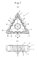
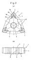
- each protrusion 6 In order to restrain the insert as stably as possible on a holder, each protrusion 6 should have a sufficiently large contact surface area with a V-shaped recess formed in the seating face of the holder. Taking also into consideration the wedging effect when the V-shaped protrusions 6 are engaged in the V-shaped recesses in the seating face of the holder, and the strength of the protrusions 6, each protrusion 6 preferably comprises two flat surfaces 6a forming an angle ⁇ of 60 to 120 degrees as viewed from the top of the insert. More preferably, the value ⁇ is about 90 degrees, because such protrusions 6 are substantially identical in shape and size to the protrusions formed on the seating face of the holder.
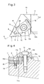
- the seating groove 12 includes a bottom seating face 12a on which the insert is seated, and a side wall 12b which restrains one of the three sides of the insert 1.
- the top surface of the bottom plate 15 defines the bottom seating face 12a.
- the side wall 12b of the seating groove is defined by the piece 14.
- the piece 14 is fixed in position by fitting the piece 14 in a recess 17 formed in the holder 11, engaging the bottom plate 15 in a cutout 14a formed in a lower portion of the front face of the piece 14, and fixing the holder 11 by clamping it with the set screw 16. But a separate fastener or set screw may be used to fix the piece 14 separately from the bottom plate 15.
- the bottom plate 15 may be omitted.
- the insert 1 tends to shift and cannot be positioned with high accuracy.
- at least two such protrusions 6 have to be formed on each side of the insert, which are engaged in two respective V-shaped grooves formed in the side wall 12b at such points that the insert can be held in position with good balance.
Landscapes
- Engineering & Computer Science (AREA)
- Mechanical Engineering (AREA)
- Cutting Tools, Boring Holders, And Turrets (AREA)
Abstract
Description
Claims (8)
- A plate-shaped cutting insert with multiple alternately usable cutting edges having basically the shape of an equilateral triangle and including three acute corners and sides between said corners, each of said sides being formed with a V-shaped recess and at least two V-shaped protrusions as seen from the top of the insert, said recess and said protrusions being adapted to be brought into engagement with a protrusion and recesses formed on a side wall of a holder, said protrusions on each side being symmetrical with respect to a line connecting the center of said insert with the center of said each side.
- The plate-shaped cutting insert with multiple alternately usable cutting edges of claim 1 wherein each of said protrusion is defined by two flat surfaces forming an angle of 60 to 120 degrees as seen from the top of the insert.
- The plate-shaped cutting insert with multiple alternately usable cutting edges of claim 1 or 2 wherein each of said three corners has an apex angle of 35 to 80 degrees.
- The plate-shaped cutting insert with multiple alternately usable cutting edges of any of claims 1 to 3 wherein said protrusions have apexes that are located on or inside of lines connecting said corners.
- The plate-shaped cutting insert with multiple alternately usable cutting edges of any of claims 1 to 4 wherein there are provided three or more of said protrusions, said three or more protrusions being arranged with equal pitches.
- The plate-shaped cutting insert with multiple alternately usable cutting edges of any of claims 1 to 5 wherein said protrusions and recesses have sintered surfaces.
- A cutting tool comprising a holder having at its front end a seating groove including a side wall and a bottom seating face, and the insert of any of claims 1 to 6, which is seated in said seating groove, said insert being fixed to said holder by bringing said protrusions and recess formed on one of said sides into engagement with respective recesses and protrusion formed on said side wall of said holder and pressing said insert against said bottom seating face and said side wall with a clamp means.
- The cutting tool of claim 7 further comprising a piece detachably mounted to the side wall of said holder and fixed to said holder by means of a fastener, said piece being formed with said recesses and protrusion adapted to be brought into engagement with said protrusions and recess formed on one of said sides of said insert.
Applications Claiming Priority (3)
| Application Number | Priority Date | Filing Date | Title |
|---|---|---|---|
| JP2003036347A JP4155838B2 (en) | 2003-02-14 | 2003-02-14 | Replaceable blade tip and cutting tool using the same |
| JP2003036347 | 2003-02-14 | ||
| PCT/JP2004/001510 WO2004071695A1 (en) | 2003-02-14 | 2004-02-12 | Edge replacement tip and cutting tool using the same |
Publications (3)
| Publication Number | Publication Date |
|---|---|
| EP1598132A1 true EP1598132A1 (en) | 2005-11-23 |
| EP1598132A4 EP1598132A4 (en) | 2011-04-13 |
| EP1598132B1 EP1598132B1 (en) | 2016-06-15 |
Family
ID=32866326
Family Applications (1)
| Application Number | Title | Priority Date | Filing Date |
|---|---|---|---|
| EP04710549.9A Expired - Lifetime EP1598132B1 (en) | 2003-02-14 | 2004-02-12 | Cutting insert and cutting tool using the same |
Country Status (7)
| Country | Link |
|---|---|
| US (1) | US8459162B2 (en) |
| EP (1) | EP1598132B1 (en) |
| JP (1) | JP4155838B2 (en) |
| KR (1) | KR101052658B1 (en) |
| CN (1) | CN100420530C (en) |
| IL (1) | IL169958A (en) |
| WO (1) | WO2004071695A1 (en) |
Cited By (2)
| Publication number | Priority date | Publication date | Assignee | Title |
|---|---|---|---|---|
| EP1846182B1 (en) * | 2005-02-11 | 2012-08-01 | Sandvik Intellectual Property AB | Indexable cutting insert and cutting insert holder |
| WO2019166053A1 (en) * | 2018-02-27 | 2019-09-06 | Zcc Cutting Tools Europe Gmbh | Cutting insert for machining |
Families Citing this family (29)
| Publication number | Priority date | Publication date | Assignee | Title |
|---|---|---|---|---|
| SE528710C2 (en) * | 2005-06-01 | 2007-01-30 | Sandvik Intellectual Property | Indexable cutter with the coupling means arranged on a release surface |
| JP4899375B2 (en) * | 2005-08-08 | 2012-03-21 | コニカミノルタオプト株式会社 | Cutting tool, processing apparatus, and cutting method |
| JP4797526B2 (en) * | 2005-09-13 | 2011-10-19 | 株式会社タンガロイ | Throwaway tip |
| DE102006016626A1 (en) * | 2006-04-06 | 2007-10-11 | Kennametal Widia Produktions Gmbh & Co. Kg | Cutting insert and method for machining of rotating moving workpieces |
| SE534512C2 (en) * | 2009-06-24 | 2011-09-13 | Sandvik Intellectual Property | Tools for chip separating machining as well as solid indexable cutting and solid foundation for this |
| US8662208B2 (en) | 2010-06-17 | 2014-03-04 | American National Carbide Co. | Downhole cutting tool, cutting elements and method |
| JP2012086303A (en) * | 2010-10-19 | 2012-05-10 | Sumitomo Electric Hardmetal Corp | Cutting edge replacement type tip and method for manufacturing the same |
| CN102335762A (en) * | 2011-08-03 | 2012-02-01 | 四川欧曼机械有限公司 | Cutting cutter |
| US8573905B2 (en) * | 2012-03-22 | 2013-11-05 | Iscar, Ltd. | Triangular cutting insert and cutting tool |
| CN102862099B (en) * | 2012-05-30 | 2014-12-17 | 厦门钨业股份有限公司 | Dedicated jig for numerical control knife machine |
| US9849514B2 (en) * | 2013-05-28 | 2017-12-26 | Kyocera Corporation | Cutting insert and cutting tool, and method for producing cut workpieces using cutting tool |
| CN103317318B (en) * | 2013-06-26 | 2015-09-23 | 谢腾 | Replaceable repeatedly-grinding special-shaped forming cutter and forming method |
| USD755266S1 (en) * | 2013-10-30 | 2016-05-03 | Sumitomo Electric Hardmetal Corp. | Throw away tip for metal cutting tool |
| US10005131B2 (en) * | 2014-03-25 | 2018-06-26 | Kennametal Inc. | Triangular-shaped cutting insert with twelve cutting edges and tool holder therefor |
| USD748169S1 (en) * | 2014-04-17 | 2016-01-26 | Sumitomo Electric Hardmetal Corp. | Throw-away tip for metal cutting tool |
| CN104044192B (en) * | 2014-05-30 | 2016-01-20 | 滨州市虎森数控机械研究所 | One is heightened and is changed a numerical control woodworking lathe tool |
| JP6528781B2 (en) * | 2014-12-10 | 2019-06-12 | 株式会社タンガロイ | Cutting inserts, tool bodies and cutting tools |
| WO2016098775A1 (en) * | 2014-12-17 | 2016-06-23 | 京セラ株式会社 | Cutting insert, cutting tool, and method for manufacturing cut product |
| USD800188S1 (en) * | 2015-03-19 | 2017-10-17 | Sumitomo Electric Hardmetal Corp. | Throw-away tip for metal cutting tool |
| USD799572S1 (en) | 2015-03-19 | 2017-10-10 | Sumitomo Electric Hardmetal Corp. | Throw-away tip for metal cutting tool |
| US20170014922A1 (en) * | 2015-07-15 | 2017-01-19 | Caterpillar Inc. | Power Skiving Assembly and Method of Operation of Same |
| US20170120351A1 (en) * | 2015-11-03 | 2017-05-04 | Kennametal Inc. | Double-sided cutting inserts with positive clearance face geometry |
| CN107214380A (en) * | 2016-03-22 | 2017-09-29 | 日铕股份有限公司 | Circular saw blade with increased adhesive area |
| JP6708183B2 (en) | 2017-08-10 | 2020-06-10 | 株式会社タンガロイ | Cutting insert and cutting tool |
| JP6919824B2 (en) * | 2020-01-15 | 2021-08-18 | 株式会社タンガロイ | Cutting inserts and turning tools using the cutting inserts |
| US11897038B2 (en) | 2020-09-30 | 2024-02-13 | Iscar, Ltd. | Curved face grooving blade and face grooving holder therefor |
| USD956354S1 (en) | 2020-11-25 | 2022-06-28 | Matt Beck | Hair cutting razor |
| JP7299936B2 (en) | 2021-02-19 | 2023-06-28 | 株式会社タンガロイ | Cutting tools, cutting inserts and holding fixtures |
| EP4393620A1 (en) * | 2022-12-29 | 2024-07-03 | Walter Ag | Turning insert |
Family Cites Families (29)
| Publication number | Priority date | Publication date | Assignee | Title |
|---|---|---|---|---|
| US3500523A (en) * | 1967-08-14 | 1970-03-17 | Saginaw Machine & Tool Co | Tool holder construction |
| FR2317986A1 (en) | 1975-07-18 | 1977-02-11 | Nanini Antoine | Low power cutting tool for cast iron - has edge indentations of continuous uniform trapezoidal form of ceramic or carbide |
| US4068976A (en) * | 1976-06-29 | 1978-01-17 | Kennametal Inc. | Cutting insert configuration |
| JPS5848282B2 (en) | 1977-05-14 | 1983-10-27 | 三菱マテリアル株式会社 | clamp device |
| US4140431A (en) * | 1977-11-18 | 1979-02-20 | Kennametal Inc. | Cutting insert |
| GB2081142A (en) * | 1980-08-04 | 1982-02-17 | Wimet Ltd | Profiling Insert and Holder |
| JPS60217005A (en) * | 1984-04-12 | 1985-10-30 | Toshiba Corp | Cutting tool |
| US4602897A (en) * | 1984-04-25 | 1986-07-29 | Iscar Metals, Inc. | Cutting insert and grooving cutter |
| JPS60178504U (en) * | 1984-05-07 | 1985-11-27 | 住友電気工業株式会社 | Throwaway tip |
| SE454420B (en) * | 1984-05-14 | 1988-05-02 | Santrade Ltd | HAPPENS FOR LONG, SLIPPING OR COPYRUPTING |
| JPS6114089A (en) | 1984-06-29 | 1986-01-22 | Sumitomo Metal Ind Ltd | Spot welding method |
| JPS6150604A (en) | 1984-08-20 | 1986-03-12 | Nitto Electric Ind Co Ltd | Thermo-pervaporation apparatus |
| JPS6150604U (en) | 1984-09-05 | 1986-04-05 | ||
| SE455676B (en) * | 1984-11-12 | 1988-08-01 | Sandvik Ab | SHORT CARE, AND THEREFORE HAPPEN |
| GB2179281B (en) * | 1985-08-21 | 1989-12-06 | Gen Electric | Cutting tool insert having cutting edges with recesses |
| USD305662S (en) * | 1988-01-22 | 1990-01-23 | Kennametal Inc. | Cutting tool insert |
| JPH0619162B2 (en) | 1988-09-20 | 1994-03-16 | ダイキン工業株式会社 | Fluid actuator control device |
| JPH0285504U (en) * | 1988-12-20 | 1990-07-05 | ||
| US5000626A (en) * | 1988-12-22 | 1991-03-19 | Gte Valenite Corporation | Cutting insert for low ranges of feed and depth of cut |
| US5308197A (en) * | 1990-01-23 | 1994-05-03 | Threading Systems, Inc. | Machining apparatus |
| DE4126241A1 (en) * | 1991-08-08 | 1993-02-11 | Krupp Widia Gmbh | CUTTING INSERT AND DRILLING TOOL FOR HOLES IN FULL MATERIAL |
| SE502541C2 (en) * | 1992-02-05 | 1995-11-06 | Sandvik Ab | Chip separating inserts with precise location-determining dimensions, as well as process for its preparation |
| WO1996008331A1 (en) * | 1994-09-13 | 1996-03-21 | Widia Gmbh | Cutting insert |
| IL115338A (en) * | 1995-09-18 | 1999-07-14 | Iscar Ltd | Exchangeable cutting insert and a tool assembly for use therewith |
| IL119776A0 (en) * | 1996-12-06 | 1997-03-18 | Iscar Ltd | Cutting tool assembly |
| SE511928C2 (en) * | 1997-03-19 | 1999-12-20 | Sandvik Ab | Device and method of clamping inserts |
| JPH10328909A (en) | 1997-05-28 | 1998-12-15 | Hitachi Tool Eng Co Ltd | Indexable inserts and their holders |
| USD411551S (en) * | 1998-07-02 | 1999-06-29 | Bernadic Thomas J | Polygonal indexable cutting insert |
| US6527485B1 (en) * | 2000-11-22 | 2003-03-04 | Tooling Specialties, Inc. | Threading apparatus |
-
2003
- 2003-02-14 JP JP2003036347A patent/JP4155838B2/en not_active Expired - Lifetime
-
2004
- 2004-02-12 CN CNB2004800039896A patent/CN100420530C/en not_active Expired - Lifetime
- 2004-02-12 WO PCT/JP2004/001510 patent/WO2004071695A1/en not_active Ceased
- 2004-02-12 KR KR1020057014868A patent/KR101052658B1/en not_active Expired - Fee Related
- 2004-02-12 US US10/545,158 patent/US8459162B2/en active Active
- 2004-02-12 EP EP04710549.9A patent/EP1598132B1/en not_active Expired - Lifetime
-
2005
- 2005-07-28 IL IL169958A patent/IL169958A/en active IP Right Grant
Cited By (2)
| Publication number | Priority date | Publication date | Assignee | Title |
|---|---|---|---|---|
| EP1846182B1 (en) * | 2005-02-11 | 2012-08-01 | Sandvik Intellectual Property AB | Indexable cutting insert and cutting insert holder |
| WO2019166053A1 (en) * | 2018-02-27 | 2019-09-06 | Zcc Cutting Tools Europe Gmbh | Cutting insert for machining |
Also Published As
| Publication number | Publication date |
|---|---|
| EP1598132A4 (en) | 2011-04-13 |
| CN1747806A (en) | 2006-03-15 |
| JP4155838B2 (en) | 2008-09-24 |
| US8459162B2 (en) | 2013-06-11 |
| CN100420530C (en) | 2008-09-24 |
| KR20050102108A (en) | 2005-10-25 |
| IL169958A (en) | 2010-04-29 |
| WO2004071695A1 (en) | 2004-08-26 |
| KR101052658B1 (en) | 2011-07-28 |
| US20060257216A1 (en) | 2006-11-16 |
| EP1598132B1 (en) | 2016-06-15 |
| JP2004261883A (en) | 2004-09-24 |
Similar Documents
| Publication | Publication Date | Title |
|---|---|---|
| EP1598132B1 (en) | Cutting insert and cutting tool using the same | |
| EP2403675B1 (en) | Cutting insert with recessed insert supporting surface, and cutting tool | |
| US6948889B2 (en) | Tool and cutting insert for chip removing machining | |
| EP2638994B1 (en) | A cutting insert and a basic body for tools for chip removing machining | |
| US6379087B1 (en) | Cutting insert with split face clamping surfaces and toolholder therefor | |
| JP6023822B2 (en) | Cutting tool and cutting insert | |
| AU702747B2 (en) | Tool holder for inserts, including a ribbed clamping surface | |
| KR101323558B1 (en) | Insert with a mounting hole and toolholder including a cutting insert | |
| US8449225B2 (en) | Cutting tool and cutting insert therefor | |
| JP2000503912A (en) | Cutting inserts for roughing and precision cutting | |
| US11498139B2 (en) | Saw tooth and insert therefor | |
| CN101547762A (en) | Tool holder, in particular for a grooving tool, and cutting body for a tool holder | |
| EP1569769B1 (en) | Cutting insert with an astral recess for recieving the clamp | |
| JP4709374B2 (en) | Throw-away inserts for turning tools and insert mounting seats for turning tools | |
| US20250303475A1 (en) | Turning insert, turning tool body and turning tool for cutting metal workpieces | |
| JP2001310204A (en) | Indexable inserts and tool holders for grooving | |
| US7011476B1 (en) | Double-ended grooving and turning tool with clamping surfaces | |
| JPH09108909A (en) | Throw-away tip and its clamping mechanism | |
| JP2004160620A (en) | Indexable inserts and indexable cutting tools | |
| JPH0976111A (en) | Indexable milling tools | |
| JP2602779Y2 (en) | Clamp tool | |
| JP2026503227A (en) | Turning Inserts | |
| JP2006116681A (en) | Tip clamping device and throw-away type cutting tool with the same | |
| JP2002346832A (en) | Indexable tip | |
| JPH0512026U (en) | Throw-away side cutter |
Legal Events
| Date | Code | Title | Description |
|---|---|---|---|
| PUAI | Public reference made under article 153(3) epc to a published international application that has entered the european phase |
Free format text: ORIGINAL CODE: 0009012 |
|
| 17P | Request for examination filed |
Effective date: 20050816 |
|
| AK | Designated contracting states |
Kind code of ref document: A1 Designated state(s): AT BE BG CH CY CZ DE DK EE ES FI FR GB GR HU IE IT LI LU MC NL PT RO SE SI SK TR |
|
| AX | Request for extension of the european patent |
Extension state: AL LT LV MK |
|
| DAX | Request for extension of the european patent (deleted) | ||
| RBV | Designated contracting states (corrected) |
Designated state(s): DE SE |
|
| RBV | Designated contracting states (corrected) |
Designated state(s): DE SE |
|
| A4 | Supplementary search report drawn up and despatched |
Effective date: 20110310 |
|
| 17Q | First examination report despatched |
Effective date: 20110517 |
|
| GRAP | Despatch of communication of intention to grant a patent |
Free format text: ORIGINAL CODE: EPIDOSNIGR1 |
|
| INTG | Intention to grant announced |
Effective date: 20160108 |
|
| GRAS | Grant fee paid |
Free format text: ORIGINAL CODE: EPIDOSNIGR3 |
|
| GRAA | (expected) grant |
Free format text: ORIGINAL CODE: 0009210 |
|
| AK | Designated contracting states |
Kind code of ref document: B1 Designated state(s): DE SE |
|
| REG | Reference to a national code |
Ref country code: DE Ref legal event code: R096 Ref document number: 602004049445 Country of ref document: DE |
|
| REG | Reference to a national code |
Ref country code: SE Ref legal event code: TRGR |
|
| REG | Reference to a national code |
Ref country code: DE Ref legal event code: R097 Ref document number: 602004049445 Country of ref document: DE |
|
| PLBE | No opposition filed within time limit |
Free format text: ORIGINAL CODE: 0009261 |
|
| STAA | Information on the status of an ep patent application or granted ep patent |
Free format text: STATUS: NO OPPOSITION FILED WITHIN TIME LIMIT |
|
| 26N | No opposition filed |
Effective date: 20170316 |
|
| PGFP | Annual fee paid to national office [announced via postgrant information from national office to epo] |
Ref country code: SE Payment date: 20190212 Year of fee payment: 16 |
|
| REG | Reference to a national code |
Ref country code: SE Ref legal event code: EUG |
|
| PG25 | Lapsed in a contracting state [announced via postgrant information from national office to epo] |
Ref country code: SE Free format text: LAPSE BECAUSE OF NON-PAYMENT OF DUE FEES Effective date: 20200213 |
|
| PGFP | Annual fee paid to national office [announced via postgrant information from national office to epo] |
Ref country code: DE Payment date: 20221229 Year of fee payment: 20 |
|
| P01 | Opt-out of the competence of the unified patent court (upc) registered |
Effective date: 20230515 |
|
| REG | Reference to a national code |
Ref country code: DE Ref legal event code: R071 Ref document number: 602004049445 Country of ref document: DE |