EP1598117A1 - Liquid-like body-jetting adapter and liquid-like body feeder/container - Google Patents
Liquid-like body-jetting adapter and liquid-like body feeder/container Download PDFInfo
- Publication number
- EP1598117A1 EP1598117A1 EP04713660A EP04713660A EP1598117A1 EP 1598117 A1 EP1598117 A1 EP 1598117A1 EP 04713660 A EP04713660 A EP 04713660A EP 04713660 A EP04713660 A EP 04713660A EP 1598117 A1 EP1598117 A1 EP 1598117A1
- Authority
- EP
- European Patent Office
- Prior art keywords
- liquid
- port
- spraying
- liquid reservoir
- reservoir
- Prior art date
- Legal status (The legal status is an assumption and is not a legal conclusion. Google has not performed a legal analysis and makes no representation as to the accuracy of the status listed.)
- Granted
Links
Images


Classifications
-
- B—PERFORMING OPERATIONS; TRANSPORTING
- B05—SPRAYING OR ATOMISING IN GENERAL; APPLYING FLUENT MATERIALS TO SURFACES, IN GENERAL
- B05B—SPRAYING APPARATUS; ATOMISING APPARATUS; NOZZLES
- B05B7/00—Spraying apparatus for discharge of liquids or other fluent materials from two or more sources, e.g. of liquid and air, of powder and gas
- B05B7/24—Spraying apparatus for discharge of liquids or other fluent materials from two or more sources, e.g. of liquid and air, of powder and gas with means, e.g. a container, for supplying liquid or other fluent material to a discharge device
- B05B7/2402—Apparatus to be carried on or by a person, e.g. by hand; Apparatus comprising containers fixed to the discharge device
- B05B7/2405—Apparatus to be carried on or by a person, e.g. by hand; Apparatus comprising containers fixed to the discharge device using an atomising fluid as carrying fluid for feeding, e.g. by suction or pressure, a carried liquid from the container to the nozzle
- B05B7/2424—Apparatus to be carried on or by a person, e.g. by hand; Apparatus comprising containers fixed to the discharge device using an atomising fluid as carrying fluid for feeding, e.g. by suction or pressure, a carried liquid from the container to the nozzle the carried liquid and the main stream of atomising fluid being brought together downstream of the container before discharge
Definitions
- the present invention relates to a liquid-spraying instrument that is used for spraying various liquids, such as washing solution, coating, paint solution, foamy agent, anti-rust agent, and rust-blackening liquid and, in addition, a variety of oils, a variety of waters, or aqueous solutions.
- the present invention relates to a liquid-spraying adapter that connects to the nozzle of a compressed gas supply means of an air gun and the like and uses the compressed gas thereof to spray a liquid, and to a liquid-supplying liquid reservoir that provides this liquid-spraying adapter with a liquid.
- the present invention provides, as a novel liquid-spraying instrument that may be substituted for an aerosol container, a liquid-spraying instrument that connects to the nozzle of a compressed gas supply means of an air gun and the like and uses the compressed gas thereof to allow a liquid to be sprayed.
- the present inventor focused on a compressed gas supply means of an air gun and the like installed in a number of factories, industrial institutions, and the like, regardless of the type of operation, such as plastic-forming factory and automotive repair factory, and developed a liquid-spraying instrument that directly uses preexisting compressed gas supply means to allow various liquids to be sprayed simply.
- the liquid-spraying instrument of the present invention is provided with a liquid-spraying adapter that connects to the nozzle of a compressed gas supply means of an air gun and the like and uses the compressed gas thereof to allow a liquid to be sprayed, and a liquid-supplying liquid reservoir that provides the liquid-spraying adapter with a liquid.
- the above liquid-spraying adapter is characterized by the provision of a connecting port that may be removably connected to the nozzle of a compressed gas supply means, a liquid-spraying nozzle port that sprays a liquid, a liquid reservoir coupling port that may removably couple a liquid-supplying liquid reservoir housing a liquid, a communicating passage that communicates between the connecting port and the liquid-spraying nozzle port, and a liquid supply passage that communicates between the communicating passage and the liquid reservoir coupling port, which may aspirate the liquid inside the liquid-supplying liquid reservoir when compressed gas flows inside the communicating passage.
- liquid-supplying liquid reservoir (also referred to as “liquid reservoir”) is provided with a liquid reservoir portion that is able to house a liquid and expandable and contractible and a coupling port/liquid supply port, and is characterized by the provision of a constitution wherein, when the interior of the liquid reservoir portion is aspirated via the coupling port/liquid supply port, the internal liquid is sent out from the coupling port/liquid supply port while the liquid reservoir portion contracts.
- the liquid-spraying instrument of the present invention can spray various liquids simply by connecting to the nozzle of a compressed gas supply means of an air gun and the like that are already installed in most factories and industrial institutions and can be used extremely inexpensively and simply. Moreover, it can be used permanently if a liquid is supplied to the liquid reservoir. In addition, since it is also possible to spray different liquids by exchanging the liquid reservoir, the problem of disposal treatment of the aerosol container can also be solved. Furthermore, since compressed gas from a compressed gas supply means, such as an air gun is used, it can be used in broader applications compared to an aerosol container, e.g., liquid can be sprayed more strongly compared to an aerosol container.
- compressed gas supply means intends to include any apparatus or tool that supplies compressed gas (also referred to as “compressed gas supply apparatus or tool”), such as a compressor, a pump, an air gun, and a spray gun, and the "nozzle” thereof is the front extremity of a spraying tool that sprays a compressed gas supplied by the compressed gas supply apparatus or tool, for instance, the nozzle and the like of an air gun and so on.
- compressed gas supply apparatus or tool such as a compressor, a pump, an air gun, and a spray gun
- An “air gun” is a spraying tool that sprays compressed air from a compressor and the like, is, in general, provided with a grip, a trigger, a nozzle, an air nipple, and the like, and is arranged in such a way that compressed air is sent in from the air nipple, and the compressed air can be sprayed from the nozzle by operating the trigger.
- the so-called spray gun which is provided with a nipple that connects to a container that houses a liquid, such as coating, or to a hose, atomizes a liquid, such as coating, by blowing the compressed air out to spray a liquid from the nozzle, is also a type of air gun; however, in this case, it must be provided with a structure that allows only compressed air to be sprayed from the nozzle via a switch valve or the like.
- liquid includes a variety of liquids used in any application, regardless of the form, such as washing solution, coating, paint solution, foamy agent, anti-rust agent, and rust-blackening liquid and, in addition, various oils, various waters, or aqueous solutions.
- May (removably) connect to the nozzle of a compressed gas supply means includes all connective structures that may couple without leakage of compressed gas and includes, additionally, for instance, a structure that connects threadably and a structure that connects by fitting, and, for instance, a structure that connects by pressing the nozzle of a compressed gas supply means against the connecting port so that the compressed gas does not leak out, and the like.
- the liquid-spraying instrument of the present invention consists of a liquid-spraying adapter and a liquid-supplying liquid reservoir, and each can be formed as shown below.
- the liquid-spraying adapter of the present invention is provided with a connecting port that may be removably connected to the nozzle of a compressed gas supply means, a liquid-spraying nozzle port that sprays a liquid, a liquid reservoir coupling port that may removably couple a liquid-supplying liquid reservoir housing a liquid, a communicating passage that communicates between the connecting port and the liquid-spraying nozzle port, and a liquid supply passage that communicates between the communicating passage and the liquid reservoir coupling port.
- "communicating passage and liquid supply passage” preferably has a constitution wherein, when compressed gas flows inside the communicating passage, the liquid inside the liquid reservoir is aspirated via the liquid supply passage into the communicating passage.
- the concrete structure thereof can be formed arbitrarily, for instance, the constitution is such that a step portion is provided in the intermediate portion of the communicating passage, the connecting port side of the step portion being a small-diameter passage, the liquid-spraying nozzle port side of the step portion being a large-diameter passage whose diameter is larger than the small-diameter passage, and the liquid supply passage establishing a communication in the vicinity of the step portion within the large-diameter passage.
- the liquid inside the liquid reservoir can be aspirated inside the communicating passage via the liquid supply passage by flowing a compressed gas inside the communicating passage, allowing the liquid to be sprayed from the liquid-spraying nozzle port.
- the vicinity of the step portion means a range such that, when the compressed gas flown through the small-diameter passage enters the large-diameter passage and diffuses, a negative pressure is generated by the diffusion.
- a spray adjustment tool that may adjust the spraying amount, the spray shape, and the like can be connected to the liquid-spraying nozzle port of the liquid-spraying adapter provided with the above constitution. Since the spraying amount, the spray shape, and the like can be adjusted with the spray adjustment tool, it becomes even easier to use, further expanding the application.
- a selector switch that may open and close the liquid supply passage can be provided, and if such a selector switch is provided, spraying of liquid and spraying of high-pressure gas can be switched freely, allowing workability to be further increased.
- the liquid-supplying liquid reservoir (also referred to as “liquid reservoir”) is coupled to the liquid reservoir coupling port of the liquid-spraying adapter provided with the above-mentioned constitution.
- liquid reservoir coupling port of the liquid-spraying adapter provided with the above-mentioned constitution.
- the housed liquid can be sprayed from the liquid-spraying nozzle port via the communicating passage of the liquid-spraying adapter simply by coupling to the liquid reservoir coupling port of the liquid-spraying adapter and passing the compressed gas from the compressed gas supply means into the communicating passage.
- the liquid reservoir main body since the structure is such that the liquid reservoir main body contracts when aspiration occurs, the liquid reservoir main body need not be provided with an air vent; therefore, the liquid can be sprayed equally, should the liquid reservoir be used at any angle, which can be used without being upside-down.
- the opening of the coupling port is openably closed.
- the liquid reservoir is carried around in a state where a liquid is housed, as the liquid reservoir portion is expandable and contractible, there is the possibility that the liquid reservoir portion contracts, and the liquid leaks out from the coupling port.
- the opening of the coupling port is openably closed, as described above, since the opening of the coupling port is closed in the normal state, the liquid does not leak out, even if the liquid reservoir portion contracts, while by opening the blockage as necessary, the liquid can be supplied to the liquid supply adapter. Also, volatilization of the liquid can also be prevented.
- the liquid reservoir is coupled to the liquid supply adapter, and compressed gas is sprayed from the air gun, flowing only compressed gas through the interior of the communicating passage and the liquid supply passage in the liquid supply adapter becomes possible, allowing the interior of the communicating passage and the liquid supply passage to be flushed.
- the structure for openably closing the opening of the coupling port is not limited in particular.
- the opening can be openably closed by closing with a plastic sheet, film, or the like (namely, by covering with a thin part).
- the plastic sheet, film, or the like can be formed into one body with the liquid reservoir, the constitution can also be a separate body of plastic sheet, film, or the like covering the opening.
- the coupling port can also be constituted in such a way that it may removably attach a cap body whose top surface is formed to be openable, for instance, a cap body whose top surface thickness is thinly formed to be openable, and the opening of the coupling port can be openably closed by wearing the cap body.
- a structure coupling with the liquid reservoir coupling port of the liquid-spraying adapter such as, for instance, provision of a screw portion on the outer peripheral surface of the cap body, is necessary.
- the constitution is such that a cap body formed with an openable top surface, as described in the foregoing, is worn, since the blockage of the opening can be re-created by replacing the cap body, the main body of the liquid reservoir can be used repeatedly.
- the use has the purpose of flushing the interior of the adapter, as described above, since all that is needed is to wear the cap body, it is extremely simple.
- a liquid reservoir having such a constitution can also be used by coupling with a liquid-spraying adapter provided with a liquid reservoir coupling port having no means for opening the blockage of the coupling port on the liquid reservoir, from the viewpoint of preventing the leakage at the time of coupling, coupling with a liquid-spraying adapter provided with means for opening the blockage of the coupling port on the liquid reservoir is preferred.
- a liquid-spraying adapter wherein inside the liquid reservoir coupling port is provided a pointed tubular projection having a liquid supply passage on the inside, is preferred. In so doing, the tubular projection is preferably provided inside the coupling depression.
- liquid reservoir of the present invention is coupled to the liquid reservoir coupling port of a liquid-spraying adapter provided with such a constitution, since the coupling port of the liquid reservoir is closed until coupling time, the liquid does not leak out; moreover, since the blockage of the coupling port of the liquid reservoir can be opened by tearing with the tubular projection simultaneously to coupling, the liquid can be rendered supplyable to the liquid-spraying adapter.
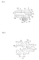
- a liquid-spraying instrument 1 was an instrument that may connect to a nozzle 101 of an air gun 100 and is provided with a liquid-spraying adapter 2 and a liquid reservoir 3, as shown in Fig. 1.
- the liquid-spraying adapter 2 as shown in Fig. 2, was provided with a connecting port 4 capable of being removably connected to the nozzle 101 of the air gun 100, a liquid-spraying nozzle port 5 for spraying a liquid, a liquid reservoir coupling port 6 capable of being removably coupled to a liquid reservoir 3, a communicating passage 7 for communicating between the connecting port 4 and the liquid-spraying nozzle port 5, and a liquid supply passage 8 for communicating between the communicating passage 7 and the liquid reservoir coupling port 6.
- the material of the adapter main body portion 2A that constitutes the main body of the liquid-spraying adapter 2 is not limited in particular and can be formed, for instance, from a synthetic resin, such as thermoplastic resin and thermosetting resin, or metal, rubber, elastomer (a resin provided with elasticity), and the like.
- a synthetic resin such as thermoplastic resin and thermosetting resin, or metal, rubber, elastomer (a resin provided with elasticity), and the like.
- molding into one body from a synthetic resin, a metal or the like is also possible; however, there is no limitation to molding into one body.
- a synthetic resin was injection molded, and in the thick-walled prismatic main body portion 2A, the connecting port 4, the liquid-spraying nozzle port 5, the liquid reservoir coupling port 6, the communicating passage 7, and the liquid supply passage 8 were molded into one body.
- one or two or more among the connecting port 4, the liquid-spraying nozzle port 5, the liquid reservoir coupling port 6, the communicating passage 7, and the liquid supply passage 8 can be formed from a material different from the main body portion 2A and subsequently fixed onto the main body portion 2A to form into one body.
- the shape of the main body portion 2A is arbitrary, and forming can be into rectangular shape, cylindrical shape, substantially conical shape, rectangular tubular shape, round tubular shape, or any other shape.
- the connecting port 4 is formed in such a way that it can couple to the nozzle 101 of the air gun 100 in a manner that is removable and may retain airtightness.
- it was constituted by providing a projection 2a from the main body portion 2A, forming on the outer peripheral surface of the projection 2a a screw portion 4a capable of being screwed into the screw portion provided in the inner peripheral surface of the nozzle 101, at the same time providing inside the projection 2a an opening 4b for communicating with the communicating passage 7.
- the liquid-spraying nozzle port 5 may have a structure that opens directly with the size of the communicating passage 7 (specifically, a large-diameter passage 7B, described below) or can be formed otherwise at will. For instance, it can be formed by varying adequately the shape and size of the opening thereof according to a shape for spraying a liquid.
- a diaphragm mechanism that allows the opening to be opened and closed at will can also be provided, such that the spraying amount, the spray shape, and the like may be adjusted.
- it can be formed to be connectable with a spray adjustment tool that may adjust the spraying amount, the spray shape, and the like, and other adapters, for instance, by forming a screw portion on the inner peripheral surface or the outer peripheral surface of the opening and the like.
- the liquid reservoir coupling port 6 was engraved by providing a projection 2b on the bottom surface of the main body portion 2A, providing a depression 6a inside the projection 2b into which the coupling port 14 may insert, and providing on the inner peripheral surface of this depression 6a a screw portion 6b capable of being screwed onto the screw portion of the coupling port 14.
- any coupling structure that may removably couple to the coupling port 14 of the liquid reservoir 3 while retaining airtightness can be adopted.
- it can be formed by embedding in the depression 6a a cap body provided with a screw portion on the inner peripheral surface.
- the communicating passage 7 was formed as a hollow space for communicating between the connecting port 4 and the liquid-spraying nozzle port 5. Specifically, as shown in Fig. 2, the communicating passage 7 was formed by providing a step portion 7C at an intermediate portion, the connecting port 4 side of this step portion 7C being a small-diameter passage 7A consisting of a hollow space with a smaller diameter, and the liquid-spraying nozzle port 5 side of the step portion 7C being the large-diameter passage 7B consisting of a hollow space with a larger diameter.
- the size of the step portion 7C namely, the difference in the diameters between the small-diameter passage 7A and the large-diameter passage 7B, is preferably approximately 5 mm or more.
- the small-diameter passage 7A may be formed, as shown in Fig. 3, by narrowing into a small diameter from the opening 4b of the connecting port 4.
- the liquid supply passage 8 was constituted in such a way that it communicated between the communicating passage 7 and the liquid reservoir coupling port 6 approximately perpendicularly to the communicating passage 7. Specifically, the liquid supply passage 8 establishes a communication in the vicinity of the step portion 7C within the large-diameter passage 7B, and when a compressed gas flows inside the communicating passage 7, the pressure inside the liquid supply passage 8 becomes negative, and the liquid inside the liquid reservoir 3 may be aspirated.
- the inside corner area (broken line portion) of this diffusion line S is the range where the pressure becomes negative, and if the liquid supply passage 8 is establishing a communication in the vicinity range (thick line portion X in the figure), the pressure inside the liquid supply passage 8 becomes negative when the compressed gas flows inside the communicating passage 7, and the liquid inside the liquid reservoir 3 can be aspirated.
- the vicinity range (thick line portion X in the figure) can be set as the portion that is more towards the step portion 7C than the position where the diffusion line S intersects the inner peripheral surface of the large-diameter passage 7B.
- the angle at which the liquid supply passage 8 intersects the communicating passage 7 is not limited in particular, and forming an intersection that is approximately perpendicular, as in the present example, or additionally, forming an intersection that is inclined at any angle is also possible.
- the size of the diameter of the liquid supply passage 8 is preferably designed to be an appropriate size that is adequate to aspirate the liquid inside the liquid reservoir 3.
- the internal diameter of the liquid supply passage 8 is preferably on the order of approximately 1.5 mm.
- the size of the diameter is not limited thereto.
- the liquid supply passage 8 can also be formed by perforating a hole in the main body portion 2A and pushing a tube member 9 inside the hole, in which case, the liquid supply passage 8 can also be formed in such a way that the tip of the tube member 9 is made to protrude inside the liquid reservoir coupling port 6, and when the coupling port 14 of the liquid reservoir 3 is coupled to the liquid reservoir coupling port 6, the tip of the tube member 9 penetrates into the coupling port 14.
- the liquid reservoir 3 was constituted by a liquid reservoir main body 11 that was capable of retaining a liquid and was expandable and contractible.
- This liquid reservoir main body 11 was formed from a synthetic resin and was constituted by a body portion 12 that was formed into a retractable accordion shape, a circular tube portion 13 protruding above the body portion 12, and a coupling portion 14 that was formed at the upper end portion of the circular tube portion 13 and was capable of being coupled removably to a liquid reservoir coupling port 6.
- the coupling portion 14 was formed to be screwable to the screw portion 6b of the liquid reservoir coupling port 6.
- liquid reservoir 3 since the liquid reservoir 3 has no air vent, it can provide the liquid-spraying adapter 2 with a liquid equally, should it be used at any angle spanning 360°, for instance, even when used upside down from the state in Fig. 7.
- the liquid reservoir 3 can also be used as a liquid storage container when not in use.
- the liquid-spraying instrument 1 was assembled by mounting the liquid reservoir 3 housing a liquid to the liquid-spraying adapter 2 by coupling the coupling portion 14 thereof to the liquid reservoir coupling port 6 of the liquid-spraying adapter 2.
- the compressed gas compressed air
- the compressed gas flows through the communicating passage 7 and blows out from the liquid-spraying nozzle port 5 while aspirating the liquid inside the liquid reservoir 3, making the liquid blow out from the liquid-spraying nozzle port 5.
- a liquid can be continuously sprayed using a compressed gas supply apparatus or tool, such as an air gun, already installed in factories and other industrial institutions and the like, without having to newly install an apparatus that sends a liquid by pressure; moreover, the liquid can be sprayed equally, should it be used at any angle spanning 360°, namely, without being upside-down.
- a compressed gas supply apparatus or tool such as an air gun, already installed in factories and other industrial institutions and the like
- Example 2 according to a liquid-spraying instrument was constituted by a liquid-spraying adapter 20 and a liquid reservoir 31, as shown in Fig. 9.
- the liquid reservoir 31 was constituted in such a way that a liquid reservoir portion 32 that was capable of housing a liquid, and was expandable and contractible, and a coupling port/liquid supply port 33 (also referred to as “coupling port”) were provided, and when the interior of the liquid reservoir portion 32 was aspirated from the coupling port 33, the liquid inside was sent out from the coupling port 33 while the liquid reservoir portion 32 contracted.
- the liquid reservoir 31 can be formed from a synthetic resin, and it suffices to suitably select the type of synthetic resin according to the type of liquid to be housed, with no particular limitation; however, a liquid reservoir portion 32 that may provide some degree of shape retainability is preferred.
- a liquid reservoir portion 32 that may provide some degree of shape retainability is preferred.
- polyethylene, polypropylene, polyethylene terephthalate, and the like can be given as preferred examples.
- the liquid reservoir portion 32 had a constitution provided with an accordion portion 34 on the side of a circular cylindrical body provided with a top surface 32a and a bottom surface 32b, the accordion portion 34 having a constitution wherein two steps or more (namely, a plurality of steps; five steps in the figure) of an projected portion (in other words, a "crease") 36, consisting of a mountain-folded portion sandwiched between valley-folded portions, were continuously provided in the top-down direction (namely, the direction that joined the coupling port 33 and the bottom surface 32b).
- Each projected portion 36 was such that the mountain folded portion projected in a triangular shape in the outward direction (namely, the direction oriented outward from the center of the liquid reservoir portion 32 in the direction perpendicular to the top-down direction) opened and closed in the top-down direction, and the entire liquid reservoir portion 32 extended and shrunk in the top-down direction.
- the extent of shape retainability with which the accordion portion 34 is provided is such that the accordion portion 34 does not extend in the top-down direction, even when a liquid is housed inside.
- the coupling port 33 was constituted in such a way that a circular tube portion 35 was protruding from the top surface 32a of the liquid reservoir portion 32, and the thickness of the top surface of this circular tube portion 35 was thinned to create an openable blockage 40.
- the blockage 40 can be molded into one body with the liquid reservoir portion 32 and the like such that the thickness becomes thin, it can also be constituted in such a way that a plastic sheet, film, or the like, which is a separate body, covers the opening.
- the coupling port 33 is constituted, on one hand, by protruding a circular tube portion 41 from the top surface 32a of the liquid reservoir portion 32 and providing a screw portion 41a on the outer peripheral surface of the circular tube portion 41, and on the other hand, by preparing, as a cap that is a separate body therefrom, a circular cylindrically shaped cap body 43 that can be removably mounted on the outside of this circular tube portion 41 and whose top surface 42 was formed to have a thin thickness and by mounting the cap body 43 to the above-mentioned circular tube portion 41.
- the cap body 43 is provided with a screw portion 43a on the inner peripheral surface thereof, which is screwable with the screw portion 41a of the above-mentioned circular tube portion 41, and that it is also provided with a screw portion 43b on the outer peripheral surface thereof.
- top surface 42 of the cap body 43 can be molded into one body with the peripheral portion and the like such that only the thickness of the top surface 42 is thin, it can also be constituted in such a way that a plastic sheet, film, or the like 44, which is a separate body from the cap body 43, covers the opening 43c of the cap body 43, as shown in Fig. 13.
- the projected portion 36A that is at the bottommost position among a plurality of projected portions 36 constituting the accordion portion 34 may have a portion, specifically, a portion of the surrounding edge protruding outwards in the radial direction, to provide a protrusion 37.
- the shape of the protrusion 37 can be formed into a triangular shape, a circular arc shape, a square shape, and any other shape, when the shape is viewed from the top surface.
- a protrusion 37 is provided in this way to the projected portion 36A, as shown in Fig. 17, by cutting the adequate intermediate portion of protrusion 37, the liquid left inside can be easily eliminated, allowing the liquid reservoir 31 to be disposed of in a state where the liquid has been completely eliminated.
- a cut line 38 can also be formed beforehand to make cutting easy. For instance, it is possible to form the cut line 38 with a thin thickness to make cutting easy.
- cutting of the protrusion 37 can be such that the proximal extremity of the protrusion 37 is completely cut off, as shown in Fig. 17; however, it can be nicked to such an extent that the liquid can be eliminated, without completely cutting it off.
- the liquid-spraying adapter 20 was provided with a connecting port 21 capable of being removably connected to the nozzle 101 of the air gun 100, a liquid-spraying nozzle port 22 for spraying a liquid, a liquid reservoir coupling port 23 capable of being removably coupled to the liquid reservoir 31, a communicating passage 24 for communicating between the connecting port 21 and the liquid-spraying nozzle port 22, and a liquid supply passage 25 for communicating between the communicating passage 24 and the liquid reservoir coupling port 23, as shown in Fig. 9 and Fig. 18.
- the material of the adapter main body 20 that constitutes the main body of the liquid-spraying adapter 20 is not limited in particular and can be formed, for instance, from a synthetic resin, such as thermoplastic resin and thermosetting resin, or metal, rubber, elastomer (a resin provided with elasticity), and the like.
- a synthetic resin such as thermoplastic resin and thermosetting resin, or metal, rubber, elastomer (a resin provided with elasticity), and the like.
- Molding into one body from a synthetic resin, a metal or the like is also possible; however, there is no limitation to molding into one body.
- the connecting port 21 was formed in such a way that it could couple to the nozzle 101 of the air gun 100 in a manner that was removable and capable of retaining airtightness.
- the connecting port 21 was constituted by providing the adapter main body 20 with a circular tubular projection 21a, forming on the outer peripheral surface of the projection 21a a screw portion 21b capable of being screwed into the screw portion provided on the inner peripheral surface of the nozzle 101, and providing inside the projection 21a an opening 21c for communicating with the communicating passage 24.
- the connecting port 21 can couple to the nozzle 101 of the air gun 100 in a manner that is removable and may retain airtightness
- the connecting structure thereof can be formed arbitrarily.
- it can also have a constitution wherein a nozzle contact opening is provided with a tapered surface that continuously opens outwards from the open extremity of the communicating passage 24, allowing the tip (nozzle 101) of the air gun 100 to be in contact with the taper face in an approximately airtight state.
- the liquid-spraying nozzle port 22 may have a structure that opens directly with the size of the communicating passage 24 (specifically, a large-diameter passage 24B, described below) or can be formed otherwise at will. For instance, it can be formed by varying adequately the shape and size of the opening thereof, according to the shape for spraying the liquid. In addition, a diaphragm mechanism that allows the opening to be opened and closed at will can also be provided, such that the spraying amount, the spray shape, and the like may be adjusted.
- it can be formed to be connectable with a spray adjustment tool that may adjust the spraying amount, the spray shape, and the like, and other adapters, for instance, by forming a screw portion on the inner peripheral surface or the outer peripheral surface of the opening and the like.
- the liquid reservoir coupling port 23 was provided by providing a projection 23a on the bottom surface of the adapter main body 20A, providing a coupling depression 23b that opened downwards inside the projection 23a, and providing a screw portion 23c on the inner peripheral surface of this coupling depression 23b, while protruding a tubular projection 26 at a central portion inside the coupling depression 23b, as shown in Fig. 10 and Fig. 18.
- the tubular projection 26 had a tip 26a formed into a tapered shape (pointed shape) to allow the blockage 40 of the coupling port 33 of the liquid reservoir 31 to be punched through, the liquid supply passage 25 passing inside and opening at the tip 26a.
- the communicating passage 24 was formed as a hollow space for communicating between the connecting port 21 and the liquid-spraying nozzle port 22. Specifically, as shown in Fig. 10 and Fig. 18, it was formed by providing a step portion 24C at an intermediate portion, the connecting port 21 side of this step portion 24C being a small-diameter passage 24A, consisting of a hollow space with a smaller diameter, and the liquid-spraying nozzle port 22 side of the step portion 24C being a large-diameter passage 24B, consisting of a hollow space with a larger diameter.
- the size of the step portion 24C namely, the difference in the diameters between the small-diameter passage 24A and the large-diameter passage 24B, is preferably approximately 5 mm or more.
- small-diameter passage 24A may be formed by narrowing into a small diameter from the opening 21c of the connecting port 21.
- the liquid supply passage 25 was constituted in such a way that it communicated between the communicating passage 24 and the liquid reservoir coupling port 23 approximately perpendicularly to the communicating passage 24. Specifically, the liquid supply passage 25 establishes a communication in the vicinity of the step portion 24C within the large-diameter passage 24B, and when a compressed gas flows inside the communicating passage 24, the pressure inside the liquid supply passage 25 becomes negative, and the liquid inside the liquid reservoir 31 may be aspirated.
- the adapter main body portion 2A in such a way that the liquid inside the liquid reservoir 31 is aspirated into the communicating passage 24 when a compressed gas is flown through the communicating passage 24, a constitution wherein the diameter of the communicating passage 24 is made larger than the liquid-spraying nozzle port 22 side via the step portion 24C while the liquid supply passage 25 is coupled in the vicinity of the step portion 24C within the large-diameter passage 24B of the communicating passage 24 having an expanded diameter, is sufficient.
- the angle at which the liquid supply passage 25 intersects the communicating passage 24 is not limited in particular, and an intersection that is approximately perpendicular, as in the present example, may be formed, or, additionally, an intersection that is inclined at any angle may also be formed.
- the size of the diameter of the liquid supply passage 25 is preferably designed to be an appropriate size that is adequate to aspirate the liquid inside the liquid reservoir 31.
- the internal diameter of the liquid supply passage 25 is preferably on the order of approximately 1.5 mm.
- the size of the diameter is not limited thereto.
- the interior of the liquid reservoir portion 32 of the liquid reservoir 31 is prefilled with a desired liquid A, and the opening of the coupling port 33 is openably covered with the blockage 40.
- the liquid reservoir 31 that houses the liquid A in this way is coupled to the liquid reservoir coupling port 23 of the liquid-spraying adapter 20, as shown in Fig. 10 and Fig. 11.
- packing is placed, as necessary, inside the coupling depression 23b of the liquid reservoir coupling port 23, and the circular tube portion 35 of the coupling port 33 is inserted into the coupling depression 23b and twisted in while screwing the screw portion 23c and the screw portion 33a.
- the tip of the tubular projection 26 pierces through the blockage 40 to open the blockage 40, and the tip of the tubular projection 26 penetrates into the liquid reservoir portion 32.
- the coupling port 33 of the liquid reservoir 31 and the liquid reservoir coupling port 23 of the liquid-spraying adapter 20 can be coupled in a manner that maintains the airtight state.
- the compressed gas can pass inside the communicating passage 24 and blow out from the liquid-spraying nozzle port 22, while at the same time, the compressed gas flowing through the communicating passage 24 aspirates the interior of the liquid reservoir 31.
- the liquid reservoir portion 32 of the liquid reservoir 31 shrinks while the liquid A inside flows out from the coupling port 33 to the liquid supply passage 25 (it can also be stated that the liquid inside flows out from the coupling port 33 while the liquid reservoir portion 32 shrinks) and can be blown out together with the compressed gas (compressed air) via the communicating passage 24 (large-diameter passage 24B) from the liquid-spraying nozzle port 22.
- liquid reservoir 31 and the liquid-spraying adapter 20 function as mentioned above, a liquid can be continuously sprayed using a compressed gas supply apparatus or tool, such as an air gun, already installed in factories and other industrial institutions and the like. Moreover, since the interior of the liquid reservoir 31 is in a sealed state, the liquid reservoir 31 can be used without being upside-down, and the liquid can be sprayed equally by the air gun and the liquid-spraying adapter 20 at any angle spanning 360°.
- the coupling port 33 and the cap body 43 in relation to the coupling portion of the liquid-spraying adapter 20; for instance, if the liquid reservoir coupling port of the liquid-spraying adapter 20 is provided with a screw portion on the outer peripheral surface, the coupling port 33 must be provided with a screw portion on the inner peripheral surface that allows coupling thereto. To this end, for instance, it suffices to constitute a cap body 43 provided with a screw portion on the inner peripheral surface, so as to be mounted inside the circular tube portion 41.
- the coupling structure between the coupling port of the liquid reservoir 31 and the coupling portion of the liquid-spraying adapter 20 is not limited to the screw-mount structure, as described above; for instance, fit-mount structure and other coupling structures can be adopted.
- the liquid left inside the liquid reservoir portion can also be easily eliminated after use by opening this hole.
- a holder member that may maintain the contracted state of the accordion portion 34.
- a constitution allowing the most shrunk state of the accordion portion 34 to be maintained is possible by fixing one extremity of the holder member at the bottom surface 32b of the liquid reservoir portion 32 on one hand, forming a locking portion that locks the other extremity of the holder member at the top surface 32a of the liquid reservoir portion 32 or at the circular tube portion 35 on the other, and locking the other extremity of the holder member onto the lock portion with the accordion portion 34 in the most shrunk state.
- the holder member may have a string shape, a belt shape, a tape shape, or any other shape.
- the structure of the lock portion can also be formed in any way, such as a structure to wind the holder member, a structure to hook a hook portion, a structure to fasten with a button, a structure to fasten with a velvet fastener, and the like.
- one extremity of the holder portion may be fixed to the top surface of the liquid reservoir portion 32 or to the circular tube portion 35 and form the lock portion on the bottom surface 32b.
- a constitution is also possible wherein a screw portion 38a for coupling use is provided at the inner peripheral portion of the circular tube portion 35 of the coupling port to serve as a coupling port 38, and a liquid receiving portion 39 is provided, extending continuously and upward into a funnel shape from the upper edge portion 38b of this coupling port 38.
- the liquid reservoir coupling port 23 of the liquid-spraying adapter 20 must be formed by providing a projection 26 on the bottom surface of the adapter main body 20A through which a liquid supply passage 25 passes and may be inserted into the circular tube portion 35, providing a screw portion 27 on the outer peripheral surface of this projection 26, to allow the liquid reservoir coupling port 23 and the coupling port 38 to be coupled, as shown in Fig. 21.
- the liquid receiving portion 39 just plays the role of a funnel, the liquid can be directly poured into the liquid reservoir portion 32 without spilling. Consequently, since when the liquid inside the liquid reservoir portion 32 becomes insufficient, the liquid reservoir 31 can be temporarily separated from the liquid-spraying adapter 20 and the liquid can be easily poured into the liquid reservoir portion 32, the liquid reservoir 31 can easily be repeatedly used.
- a liquid reservoir can be constituted as shown in Fig. 22 to Fig. 23.
- the liquid reservoir is not limited to the example described above, as long as it is provided with a liquid reservoir main body that can house a liquid and is expandable and contractible, and a coupling port.
- a liquid housing portion 51 that houses a liquid can also be formed with a plastic film bag, a rubber balloon bag, or the like, as shown in Fig. 22.
- the liquid housing portion 51 is housed inside a form-retaining container 52, consisting of metal, plastic, or the like, in order to support the liquid housing portion 51.
- a form-retaining container 52 consisting of metal, plastic, or the like
- the coupling portion 53 is preferably provided on the form-retaining container 52, and the liquid housing portion 51 is preferably constituted removably with respect to the form-retaining container 52, as shown in Fig. 24.
- the connecting port has a constitution that allows coupling to the nozzle 101 of the air gun 100 in a manner that is removable and may retain airtightness
- the connecting structure thereof can be formed at will.
- the connecting port can also be formed into a taper shape.
- the liquid-spraying adapter 62 of this constitution example consists of an entire body of resin molded into one body with a funnel shape, as shown in Fig. 25 and Fig. 26, and, similarly to the adapter with the above-mentioned constitution, is constituted such that being provided with, respectively, a nozzle-receiving portion 64 having a taper surface 69a at one extremity thereof and a metal connecting port 65 at the other extremity; at the same time, a liquid reservoir coupling port 66 formed at the lower portion thereof, a nozzle-receiving portion 64 and the metal connecting port 65 communicating via a communicating passage 67; furthermore, the communicating passage 67 and a liquid reservoir coupling port 66 communicating via a liquid supply passage 68.
- the communicating passage 67 is such that a small-diameter passage 67a with a small opening diameter is on the nozzle-receiving portion 64 side, and a large-diameter passage 67b with a large opening diameter is on the metal connecting port 65 side, a step portion 67c where both passages connect to each other continuing the space from the small-diameter passage 67a end and the large-diameter passage 67b end with a taper surface 67d, and a liquid supply passage 68 running downward from the interior of this taper surface 67d.
- the liquid reservoir coupling port 66 has a shape wherein a circular cylindrical cap form, having a screw portion at the inner periphery, is given; at the center of the bottom surface of the circular cylindrical cap part thereof, a tubular tongue piece 71 with an appropriate length that joins to the inner periphery of the coupling portion 81 of the liquid reservoir 80 protrudes as one body, the open extremity of the liquid supply passage 68 being provided at the center of the tongue piece 71.
- the liquid reservoir 80 is constituted by a liquid reservoir main body 84 consisting of a retractable accordion-shaped body portion 82 that can hold a liquid with an appropriate capacity, from the top surface of which protrudes a circular tube portion 83.
- a coupling portion 81 on the outer peripheral surface, of which is engraved a thread groove, is provided on the upper portion of the circular tube portion 83, and the inside of this coupling portion 81 is provided as a cavity which the tongue piece 71 entirely fits in and joins with.
- the liquid-spraying adapter constituted in this way is assembled by coupling the coupling portion 81 to the liquid reservoir coupling port 66 to have the liquid reservoir 80, in which the treatment solution has been placed, be mounted onto the liquid-spraying adapter 62..
- the liquid reservoir coupling port 66 of the liquid-spraying adapter 62 fits onto the coupling portion 81 of the liquid reservoir 80 to close the opening of the liquid reservoir 80; furthermore, the tongue piece 71 inserts into the inner opening of the coupling portion 81 to join with the inner peripheral surface of the opening.
Landscapes
- Nozzles (AREA)
- Polysaccharides And Polysaccharide Derivatives (AREA)
- Agricultural Chemicals And Associated Chemicals (AREA)
- Feeding And Controlling Fuel (AREA)
- Feeding, Discharge, Calcimining, Fusing, And Gas-Generation Devices (AREA)
- Devices For Dispensing Beverages (AREA)
Abstract
Description
Claims (12)
- A liquid-spraying instrument, which is a liquid-spraying instrument that may be connected to a nozzle of a compressed gas supply means and provided with a liquid-spraying adapter and a liquid-supplying liquid reservoir, wherein
said liquid-spraying adapter is provided with a connecting port that may be removably connected to the nozzle of a compressed gas supply means, the liquid-spraying nozzle port that sprays a liquid, a liquid reservoir coupling port that may be removably coupled to a liquid-supplying liquid reservoir that houses a liquid, a communicating passage that communicates between said connecting port and said liquid-spraying nozzle port, and a liquid supply passage that communicates between said communicating passage and said liquid reservoir coupling port and may aspirate the liquid inside said liquid-supplying liquid reservoir when a compressed gas flows through said communicating passage. - The liquid-spraying instrument as recited in Claim 1, wherein the nozzle of the compressed gas supply means is the nozzle of an air gun.
- The liquid-spraying instrument as recited in Claim 1 or 2 provided with a constitution, wherein the communicating passage of said liquid-spraying adapter is provided with a step portion at an intermediate portion, the connecting port side of said step portion being a small-diameter passage and the liquid-spraying nozzle port side of said step portion being a large-diameter passage whose diameter is larger than said small-diameter passage, and
said liquid supply passage establishing communication in the vicinity of said step portion within said large-diameter passage. - The liquid-spraying instrument as recited in any of Claims 1 to 3, wherein said liquid-spraying adapter is provided with a selector switch that may open and close said liquid supply passage.
- The liquid-spraying instrument as recited in any of Claims 1 to 4, wherein a spray adjustment tool that may adjust the spraying amount, spray shape, and the like is connected to said liquid-spraying nozzle port of said liquid-spraying adapter.
- The liquid-spraying instrument as recited in any of Claims 1 to 5, wherein said liquid reservoir coupling port of said liquid-spraying adapter is provided with a pointed tubular projection having a liquid supply passage on the inside.
- The liquid-spraying instrument as recited in Claim 1 with a constitution wherein said liquid-supplying liquid reservoir is provided with a liquid reservoir portion that is capable of housing a liquid and is expandable and contractible, and a coupling port/liquid supply port, the liquid inside being sent out from the coupling port/liquid supply port while the liquid reservoir portion contracts, when the interior of the liquid reservoir portion is aspirated via said coupling port/liquid supply port.
- The liquid-spraying instrument as recited in Claim 7, wherein said liquid-supplying liquid reservoir is one with the opening of said coupling port/liquid supply port openably closed.
- The liquid-spraying instrument as recited in Claim 8, wherein the opening of said coupling port/liquid supply port of said liquid-supplying liquid reservoir is closed with a plastic film or sheet.
- The liquid-spraying instrument as recited in Claim 7 with a constitution, wherein said coupling port/liquid supply port of said liquid-supplying liquid reservoir is constituted in such a way that it may have a cap body attached, whose top surface is formed to be openable, the opening of said coupling port/liquid supply port being openably closed by attaching said cap body.
- A liquid-spraying adapter, which is a liquid-spraying adapter that connects to the nozzle of a compressed gas supply means, provided with
a connecting port that may be removably connected to the nozzle of the compressed gas supply means, a liquid-spraying nozzle port that sprays a liquid, a liquid reservoir coupling port that may be removably coupled to a liquid-supplying liquid reservoir that houses a liquid, a communicating passage that communicates between said connecting port and said liquid-spraying nozzle port, and a liquid supply passage that communicates between said communicating passage and said liquid reservoir coupling port and may aspirate the liquid inside said liquid-supplying liquid reservoir when a compressed gas flows through said communicating passage. - A liquid-supplying liquid reservoir provided with a constitution, wherein a liquid reservoir portion that is capable of housing a liquid and is expandable and contractible, and a coupling port/liquid supply port are provided, the liquid inside being sent out from the coupling port/liquid supply port while the liquid reservoir portion contracts, when the interior of the liquid reservoir portion is aspirated via said coupling port/liquid supply port.
Applications Claiming Priority (9)
| Application Number | Priority Date | Filing Date | Title |
|---|---|---|---|
| JP2003047933 | 2003-02-25 | ||
| JP2003047933A JP4339610B2 (en) | 2003-02-25 | 2003-02-25 | Liquid injection adapter |
| JP2003111612A JP2004313940A (en) | 2003-04-16 | 2003-04-16 | Liquid material supply and storage device |
| JP2003111612 | 2003-04-16 | ||
| JP2003111613A JP4603769B2 (en) | 2003-04-16 | 2003-04-16 | Liquid injection equipment |
| JP2003111613 | 2003-04-16 | ||
| JP2003180903 | 2003-06-25 | ||
| JP2003180903A JP4339633B2 (en) | 2003-06-25 | 2003-06-25 | Treatment liquid supply device to the mold internal liquid passage and its lid |
| PCT/JP2004/002061 WO2004076073A1 (en) | 2003-02-25 | 2004-02-23 | Liquid-like body-jetting adapter and liquid-like body feeder/container |
Publications (3)
| Publication Number | Publication Date |
|---|---|
| EP1598117A1 true EP1598117A1 (en) | 2005-11-23 |
| EP1598117A4 EP1598117A4 (en) | 2007-08-22 |
| EP1598117B1 EP1598117B1 (en) | 2009-04-01 |
Family
ID=32931507
Family Applications (1)
| Application Number | Title | Priority Date | Filing Date |
|---|---|---|---|
| EP04713660A Expired - Lifetime EP1598117B1 (en) | 2003-02-25 | 2004-02-23 | Liquid-spraying adapter |
Country Status (6)
| Country | Link |
|---|---|
| US (1) | US20060157584A1 (en) |
| EP (1) | EP1598117B1 (en) |
| KR (1) | KR20050106451A (en) |
| AT (1) | ATE427164T1 (en) |
| DE (1) | DE602004020323D1 (en) |
| WO (1) | WO2004076073A1 (en) |
Cited By (4)
| Publication number | Priority date | Publication date | Assignee | Title |
|---|---|---|---|---|
| GB2476654A (en) * | 2009-12-30 | 2011-07-06 | Charles Wysocki | Concertina dispensing container for dosing central heating system |
| WO2011121552A2 (en) | 2010-03-30 | 2011-10-06 | L'oreal | An airbrush |
| FR2958189A1 (en) * | 2010-03-30 | 2011-10-07 | Oreal | AIR-BRUSH |
| GR20160100238A (en) * | 2016-05-16 | 2018-02-05 | Σαϊμιρ Στεφαν Μαχμουτλαρι | Hair dyeing with aerographer |
Families Citing this family (13)
| Publication number | Priority date | Publication date | Assignee | Title |
|---|---|---|---|---|
| US20070095943A1 (en) | 2005-10-28 | 2007-05-03 | Turnbull William N | Liquid reservoir, and kit, spray assembly and method using same |
| US8454360B2 (en) * | 2008-11-17 | 2013-06-04 | Koninkliijke Philips Electronics N.V. | Liquid droplet interproximal cleaning apparatus with gas stream protection |
| EP2453831B1 (en) * | 2009-07-14 | 2013-08-14 | Koninklijke Philips Electronics N.V. | Atomized liquid oral cleaning appliance |
| CN104624544A (en) * | 2015-01-16 | 2015-05-20 | 杭州大和热磁电子有限公司 | Cavity residue clearing device |
| DE202015003663U1 (en) * | 2015-05-22 | 2016-09-29 | Sata Gmbh & Co. Kg | Device for coating surfaces, in particular paint or lacquer surfaces |
| KR200492709Y1 (en) * | 2019-03-11 | 2020-11-27 | 서울특별시 | Injection apparatus |
| KR102605377B1 (en) * | 2019-10-11 | 2023-11-23 | 삼성중공업 주식회사 | An apparatus for painting of two-component type paint |
| WO2021075883A1 (en) * | 2019-10-17 | 2021-04-22 | 주식회사 함일셀레나 | Urethane foam dispensing gun assembly |
| KR102275068B1 (en) * | 2019-12-30 | 2021-07-08 | 공주대학교 산학협력단 | apparatus for oscillating fluid injection with variable volume of center flow path |
| KR102275397B1 (en) * | 2019-12-30 | 2021-07-09 | 공주대학교 산학협력단 | apparatus for oscillating fluid injection with variable length of feedback flow path |
| KR102513572B1 (en) * | 2020-07-09 | 2023-03-23 | 주식회사 케이티앤지 | Aerosol generating device |
| KR102294617B1 (en) * | 2020-10-06 | 2021-08-27 | 김남호 | Phone gripping apparatus |
| JP2025523481A (en) | 2022-07-01 | 2025-07-23 | レセンスメディカル、インコーポレイテッド | A module into which the composition is to be sprayed together with the refrigerant |
Family Cites Families (15)
| Publication number | Priority date | Publication date | Assignee | Title |
|---|---|---|---|---|
| US3113725A (en) * | 1962-09-07 | 1963-12-10 | Barco Mfg Co Inc | Valve controlled spraying device for a chemical intermixed with water |
| US3632046A (en) * | 1968-04-23 | 1972-01-04 | Robert W Hengesbach | Spray nozzle |
| JPS484605U (en) * | 1971-06-16 | 1973-01-19 | ||
| US3770209A (en) * | 1972-04-19 | 1973-11-06 | Delavan Manufacturing Co | Aspirating spray head |
| US4322020A (en) * | 1978-05-02 | 1982-03-30 | Raymond Stone | Invertible pump sprayer |
| US4804144A (en) * | 1981-09-21 | 1989-02-14 | Tekex Company | Apparatus for dispensing viscous materials |
| CA2080817A1 (en) * | 1990-04-23 | 1991-10-24 | Stephen R. Horvath, Jr. | Precision-ratioed fluid-mixing device and system |
| US5328055A (en) * | 1992-11-27 | 1994-07-12 | Battle John R | Refillable liquid dispenser with diamond-shaped inner pliant bladder |
| FR2716669A1 (en) * | 1994-04-28 | 1995-09-01 | Manuf Bourguignonne Plasti | Method of emptying a vial and closure element compliant for its implementation. |
| JPH08301322A (en) * | 1995-04-28 | 1996-11-19 | Dainippon Printing Co Ltd | Lid for sealing the opening |
| US5826795A (en) * | 1996-08-19 | 1998-10-27 | Minnesota Mining And Manufacturing Company | Spray assembly |
| JPH1128394A (en) * | 1997-07-10 | 1999-02-02 | Toshio Masuda | Closed type spray gun |
| US6042026A (en) * | 1998-07-02 | 2000-03-28 | Buehler, Ii; Louis C. | Spray nozzle |
| JP2002224591A (en) * | 2001-01-31 | 2002-08-13 | Iris Ohyama Inc | Aqua gun |
| JP3087922U (en) * | 2002-02-13 | 2002-08-23 | 武巧 周 | Multifunctional spray painting, jet cleaning dual use handle |
-
2004
- 2004-02-23 WO PCT/JP2004/002061 patent/WO2004076073A1/en not_active Ceased
- 2004-02-23 AT AT04713660T patent/ATE427164T1/en not_active IP Right Cessation
- 2004-02-23 KR KR1020057015635A patent/KR20050106451A/en not_active Ceased
- 2004-02-23 US US10/545,898 patent/US20060157584A1/en not_active Abandoned
- 2004-02-23 DE DE602004020323T patent/DE602004020323D1/en not_active Expired - Lifetime
- 2004-02-23 EP EP04713660A patent/EP1598117B1/en not_active Expired - Lifetime
Cited By (10)
| Publication number | Priority date | Publication date | Assignee | Title |
|---|---|---|---|---|
| GB2476654A (en) * | 2009-12-30 | 2011-07-06 | Charles Wysocki | Concertina dispensing container for dosing central heating system |
| GB2476654B (en) * | 2009-12-30 | 2013-12-18 | Charles Wysocki | Concertina dispensing device & adaptor |
| WO2011121552A2 (en) | 2010-03-30 | 2011-10-06 | L'oreal | An airbrush |
| FR2958189A1 (en) * | 2010-03-30 | 2011-10-07 | Oreal | AIR-BRUSH |
| FR2958188A1 (en) * | 2010-03-30 | 2011-10-07 | Oreal | AIR-BRUSH |
| WO2011121551A3 (en) * | 2010-03-30 | 2011-12-01 | L'oreal | Airbrush |
| WO2011121552A3 (en) * | 2010-03-30 | 2011-12-08 | L'oreal | A junction device for a spray system |
| US9238240B2 (en) | 2010-03-30 | 2016-01-19 | L'oreal | Airbrush |
| US9427757B2 (en) | 2010-03-30 | 2016-08-30 | L'oreal | Airbrush |
| GR20160100238A (en) * | 2016-05-16 | 2018-02-05 | Σαϊμιρ Στεφαν Μαχμουτλαρι | Hair dyeing with aerographer |
Also Published As
| Publication number | Publication date |
|---|---|
| US20060157584A1 (en) | 2006-07-20 |
| ATE427164T1 (en) | 2009-04-15 |
| EP1598117A4 (en) | 2007-08-22 |
| EP1598117B1 (en) | 2009-04-01 |
| WO2004076073A1 (en) | 2004-09-10 |
| KR20050106451A (en) | 2005-11-09 |
| DE602004020323D1 (en) | 2009-05-14 |
Similar Documents
| Publication | Publication Date | Title |
|---|---|---|
| EP1598117B1 (en) | Liquid-spraying adapter | |
| CN100408199C (en) | Liquid Injection Adapter and Liquid Supply Reservoir | |
| US6837400B2 (en) | Solvent identification bottle with adjustable dispensing feature | |
| US20070095943A1 (en) | Liquid reservoir, and kit, spray assembly and method using same | |
| US6945429B2 (en) | Disposable paint cup attachment system for gravity-feed paint sprayer | |
| CN100435972C (en) | Disposable cup for fitting to a spray gun for preparing, applying and preserving paint | |
| US6419118B1 (en) | Containers with flexible pouch and closure member | |
| US5328055A (en) | Refillable liquid dispenser with diamond-shaped inner pliant bladder | |
| US7819341B2 (en) | Paint reservoir system for a paint spray gun | |
| US7165732B2 (en) | Adapter assembly for a fluid supply assembly | |
| LV11946B (en) | COLOR SUPPLY DEVICE | |
| US20080105763A1 (en) | Device for attaching a dip tube to a fluid container | |
| EP0492333B1 (en) | Closure for nebulizable liquid containers | |
| JP2548115Y2 (en) | Spray equipment | |
| JP2003520663A5 (en) | ||
| CN104884363A (en) | Discharge container with nozzle cap | |
| JP2019051981A (en) | Installation structure of pump dispenser for bag container | |
| US5474210A (en) | Fluid dispensing device | |
| JP4603769B2 (en) | Liquid injection equipment | |
| AU2004202537A1 (en) | Disposable paint cup attachment system for gravity-feed paint sprayer | |
| JPH11253842A (en) | Spray device | |
| JP6296777B2 (en) | Discharge container with nozzle cap | |
| US8251972B2 (en) | Perforable closure for a container, mould and method for carrying out said closure | |
| JP2025136778A (en) | Liquid jetting nozzle adapter and liquid supply tool | |
| JP2004313940A (en) | Liquid material supply and storage device |
Legal Events
| Date | Code | Title | Description |
|---|---|---|---|
| PUAI | Public reference made under article 153(3) epc to a published international application that has entered the european phase |
Free format text: ORIGINAL CODE: 0009012 |
|
| 17P | Request for examination filed |
Effective date: 20050824 |
|
| AK | Designated contracting states |
Kind code of ref document: A1 Designated state(s): AT BE BG CH CY CZ DE DK EE ES FI FR GB GR HU IE IT LI LU MC NL PT RO SE SI SK TR |
|
| AX | Request for extension of the european patent |
Extension state: AL LT LV MK |
|
| DAX | Request for extension of the european patent (deleted) | ||
| A4 | Supplementary search report drawn up and despatched |
Effective date: 20070720 |
|
| 17Q | First examination report despatched |
Effective date: 20071001 |
|
| RTI1 | Title (correction) |
Free format text: LIQUID-SPRAYING ADAPTER |
|
| GRAP | Despatch of communication of intention to grant a patent |
Free format text: ORIGINAL CODE: EPIDOSNIGR1 |
|
| GRAS | Grant fee paid |
Free format text: ORIGINAL CODE: EPIDOSNIGR3 |
|
| GRAA | (expected) grant |
Free format text: ORIGINAL CODE: 0009210 |
|
| AK | Designated contracting states |
Kind code of ref document: B1 Designated state(s): AT BE BG CH CY CZ DE DK EE ES FI FR GB GR HU IE IT LI LU MC NL PT RO SE SI SK TR |
|
| REG | Reference to a national code |
Ref country code: GB Ref legal event code: FG4D |
|
| REG | Reference to a national code |
Ref country code: CH Ref legal event code: NV Representative=s name: BOVARD AG PATENTANWAELTE Ref country code: CH Ref legal event code: EP |
|
| REG | Reference to a national code |
Ref country code: IE Ref legal event code: FG4D |
|
| REF | Corresponds to: |
Ref document number: 602004020323 Country of ref document: DE Date of ref document: 20090514 Kind code of ref document: P |
|
| PG25 | Lapsed in a contracting state [announced via postgrant information from national office to epo] |
Ref country code: SI Free format text: LAPSE BECAUSE OF FAILURE TO SUBMIT A TRANSLATION OF THE DESCRIPTION OR TO PAY THE FEE WITHIN THE PRESCRIBED TIME-LIMIT Effective date: 20090401 |
|
| PG25 | Lapsed in a contracting state [announced via postgrant information from national office to epo] |
Ref country code: ES Free format text: LAPSE BECAUSE OF FAILURE TO SUBMIT A TRANSLATION OF THE DESCRIPTION OR TO PAY THE FEE WITHIN THE PRESCRIBED TIME-LIMIT Effective date: 20090712 Ref country code: EE Free format text: LAPSE BECAUSE OF FAILURE TO SUBMIT A TRANSLATION OF THE DESCRIPTION OR TO PAY THE FEE WITHIN THE PRESCRIBED TIME-LIMIT Effective date: 20090401 Ref country code: FI Free format text: LAPSE BECAUSE OF FAILURE TO SUBMIT A TRANSLATION OF THE DESCRIPTION OR TO PAY THE FEE WITHIN THE PRESCRIBED TIME-LIMIT Effective date: 20090401 Ref country code: AT Free format text: LAPSE BECAUSE OF FAILURE TO SUBMIT A TRANSLATION OF THE DESCRIPTION OR TO PAY THE FEE WITHIN THE PRESCRIBED TIME-LIMIT Effective date: 20090401 Ref country code: PT Free format text: LAPSE BECAUSE OF FAILURE TO SUBMIT A TRANSLATION OF THE DESCRIPTION OR TO PAY THE FEE WITHIN THE PRESCRIBED TIME-LIMIT Effective date: 20090902 |
|
| PG25 | Lapsed in a contracting state [announced via postgrant information from national office to epo] |
Ref country code: SE Free format text: LAPSE BECAUSE OF FAILURE TO SUBMIT A TRANSLATION OF THE DESCRIPTION OR TO PAY THE FEE WITHIN THE PRESCRIBED TIME-LIMIT Effective date: 20090701 |
|
| PG25 | Lapsed in a contracting state [announced via postgrant information from national office to epo] |
Ref country code: RO Free format text: LAPSE BECAUSE OF FAILURE TO SUBMIT A TRANSLATION OF THE DESCRIPTION OR TO PAY THE FEE WITHIN THE PRESCRIBED TIME-LIMIT Effective date: 20090401 Ref country code: DK Free format text: LAPSE BECAUSE OF FAILURE TO SUBMIT A TRANSLATION OF THE DESCRIPTION OR TO PAY THE FEE WITHIN THE PRESCRIBED TIME-LIMIT Effective date: 20090401 Ref country code: CZ Free format text: LAPSE BECAUSE OF FAILURE TO SUBMIT A TRANSLATION OF THE DESCRIPTION OR TO PAY THE FEE WITHIN THE PRESCRIBED TIME-LIMIT Effective date: 20090401 |
|
| PLBE | No opposition filed within time limit |
Free format text: ORIGINAL CODE: 0009261 |
|
| STAA | Information on the status of an ep patent application or granted ep patent |
Free format text: STATUS: NO OPPOSITION FILED WITHIN TIME LIMIT |
|
| PG25 | Lapsed in a contracting state [announced via postgrant information from national office to epo] |
Ref country code: BE Free format text: LAPSE BECAUSE OF FAILURE TO SUBMIT A TRANSLATION OF THE DESCRIPTION OR TO PAY THE FEE WITHIN THE PRESCRIBED TIME-LIMIT Effective date: 20090401 Ref country code: SK Free format text: LAPSE BECAUSE OF FAILURE TO SUBMIT A TRANSLATION OF THE DESCRIPTION OR TO PAY THE FEE WITHIN THE PRESCRIBED TIME-LIMIT Effective date: 20090401 |
|
| 26N | No opposition filed |
Effective date: 20100105 |
|
| PG25 | Lapsed in a contracting state [announced via postgrant information from national office to epo] |
Ref country code: BG Free format text: LAPSE BECAUSE OF FAILURE TO SUBMIT A TRANSLATION OF THE DESCRIPTION OR TO PAY THE FEE WITHIN THE PRESCRIBED TIME-LIMIT Effective date: 20090701 |
|
| PGFP | Annual fee paid to national office [announced via postgrant information from national office to epo] |
Ref country code: CH Payment date: 20100224 Year of fee payment: 7 |
|
| PGFP | Annual fee paid to national office [announced via postgrant information from national office to epo] |
Ref country code: NL Payment date: 20100218 Year of fee payment: 7 |
|
| PG25 | Lapsed in a contracting state [announced via postgrant information from national office to epo] |
Ref country code: MC Free format text: LAPSE BECAUSE OF NON-PAYMENT OF DUE FEES Effective date: 20100301 Ref country code: GR Free format text: LAPSE BECAUSE OF FAILURE TO SUBMIT A TRANSLATION OF THE DESCRIPTION OR TO PAY THE FEE WITHIN THE PRESCRIBED TIME-LIMIT Effective date: 20090702 |
|
| PG25 | Lapsed in a contracting state [announced via postgrant information from national office to epo] |
Ref country code: IE Free format text: LAPSE BECAUSE OF NON-PAYMENT OF DUE FEES Effective date: 20100223 |
|
| PG25 | Lapsed in a contracting state [announced via postgrant information from national office to epo] |
Ref country code: IT Free format text: LAPSE BECAUSE OF FAILURE TO SUBMIT A TRANSLATION OF THE DESCRIPTION OR TO PAY THE FEE WITHIN THE PRESCRIBED TIME-LIMIT Effective date: 20090401 |
|
| REG | Reference to a national code |
Ref country code: CH Ref legal event code: PFA Owner name: DAIZO CORPORATION Free format text: DAIZO CORPORATION#1-201, FUKUZAKI 3-CHOME, MINATO-KU#OSAKA-SHI, OSAKA 552-0013 (JP) -TRANSFER TO- DAIZO CORPORATION#1-201, FUKUZAKI 3-CHOME, MINATO-KU#OSAKA-SHI, OSAKA 552-0013 (JP) |
|
| REG | Reference to a national code |
Ref country code: NL Ref legal event code: V1 Effective date: 20110901 |
|
| REG | Reference to a national code |
Ref country code: CH Ref legal event code: PL |
|
| PG25 | Lapsed in a contracting state [announced via postgrant information from national office to epo] |
Ref country code: LI Free format text: LAPSE BECAUSE OF NON-PAYMENT OF DUE FEES Effective date: 20110228 Ref country code: CH Free format text: LAPSE BECAUSE OF NON-PAYMENT OF DUE FEES Effective date: 20110228 |
|
| PG25 | Lapsed in a contracting state [announced via postgrant information from national office to epo] |
Ref country code: NL Free format text: LAPSE BECAUSE OF NON-PAYMENT OF DUE FEES Effective date: 20110901 |
|
| PG25 | Lapsed in a contracting state [announced via postgrant information from national office to epo] |
Ref country code: CY Free format text: LAPSE BECAUSE OF FAILURE TO SUBMIT A TRANSLATION OF THE DESCRIPTION OR TO PAY THE FEE WITHIN THE PRESCRIBED TIME-LIMIT Effective date: 20090401 |
|
| PG25 | Lapsed in a contracting state [announced via postgrant information from national office to epo] |
Ref country code: HU Free format text: LAPSE BECAUSE OF FAILURE TO SUBMIT A TRANSLATION OF THE DESCRIPTION OR TO PAY THE FEE WITHIN THE PRESCRIBED TIME-LIMIT Effective date: 20091002 Ref country code: LU Free format text: LAPSE BECAUSE OF NON-PAYMENT OF DUE FEES Effective date: 20100223 |
|
| PG25 | Lapsed in a contracting state [announced via postgrant information from national office to epo] |
Ref country code: TR Free format text: LAPSE BECAUSE OF FAILURE TO SUBMIT A TRANSLATION OF THE DESCRIPTION OR TO PAY THE FEE WITHIN THE PRESCRIBED TIME-LIMIT Effective date: 20090401 |
|
| PGFP | Annual fee paid to national office [announced via postgrant information from national office to epo] |
Ref country code: FR Payment date: 20130318 Year of fee payment: 10 Ref country code: GB Payment date: 20130222 Year of fee payment: 10 |
|
| PGFP | Annual fee paid to national office [announced via postgrant information from national office to epo] |
Ref country code: DE Payment date: 20130410 Year of fee payment: 10 |
|
| REG | Reference to a national code |
Ref country code: DE Ref legal event code: R119 Ref document number: 602004020323 Country of ref document: DE |
|
| GBPC | Gb: european patent ceased through non-payment of renewal fee |
Effective date: 20140223 |
|
| REG | Reference to a national code |
Ref country code: FR Ref legal event code: ST Effective date: 20141031 |
|
| REG | Reference to a national code |
Ref country code: DE Ref legal event code: R119 Ref document number: 602004020323 Country of ref document: DE Effective date: 20140902 |
|
| PG25 | Lapsed in a contracting state [announced via postgrant information from national office to epo] |
Ref country code: DE Free format text: LAPSE BECAUSE OF NON-PAYMENT OF DUE FEES Effective date: 20140902 Ref country code: GB Free format text: LAPSE BECAUSE OF NON-PAYMENT OF DUE FEES Effective date: 20140223 Ref country code: FR Free format text: LAPSE BECAUSE OF NON-PAYMENT OF DUE FEES Effective date: 20140228 |