EP1597445B1 - Flooring systems - Google Patents
Flooring systems Download PDFInfo
- Publication number
- EP1597445B1 EP1597445B1 EP04710435A EP04710435A EP1597445B1 EP 1597445 B1 EP1597445 B1 EP 1597445B1 EP 04710435 A EP04710435 A EP 04710435A EP 04710435 A EP04710435 A EP 04710435A EP 1597445 B1 EP1597445 B1 EP 1597445B1
- Authority
- EP
- European Patent Office
- Prior art keywords
- members
- channel
- flooring system
- male connector
- connector formation
- Prior art date
- Legal status (The legal status is an assumption and is not a legal conclusion. Google has not performed a legal analysis and makes no representation as to the accuracy of the status listed.)
- Expired - Lifetime
Links
- 238000009408 flooring Methods 0.000 title claims abstract description 69
- 230000015572 biosynthetic process Effects 0.000 claims abstract description 46
- 238000005755 formation reaction Methods 0.000 claims abstract description 46
- 230000000295 complement effect Effects 0.000 claims abstract description 3
- 238000003780 insertion Methods 0.000 claims description 8
- 230000037431 insertion Effects 0.000 claims description 8
- 229920001169 thermoplastic Polymers 0.000 claims description 6
- 239000004416 thermosoftening plastic Substances 0.000 claims description 6
- 238000000034 method Methods 0.000 claims description 5
- 239000004033 plastic Substances 0.000 claims description 5
- 229920003023 plastic Polymers 0.000 claims description 5
- -1 polyethylene Polymers 0.000 claims description 5
- 241000826860 Trapezium Species 0.000 claims description 4
- 239000004743 Polypropylene Substances 0.000 claims description 3
- 229920001903 high density polyethylene Polymers 0.000 claims description 3
- 239000004700 high-density polyethylene Substances 0.000 claims description 3
- 229920001155 polypropylene Polymers 0.000 claims description 3
- 229920000915 polyvinyl chloride Polymers 0.000 claims description 3
- 239000004800 polyvinyl chloride Substances 0.000 claims description 3
- 230000000717 retained effect Effects 0.000 claims description 3
- 239000004698 Polyethylene Substances 0.000 claims description 2
- 150000001241 acetals Chemical class 0.000 claims description 2
- 230000008602 contraction Effects 0.000 claims description 2
- 230000009970 fire resistant effect Effects 0.000 claims description 2
- 229920000573 polyethylene Polymers 0.000 claims description 2
- 239000000463 material Substances 0.000 description 11
- 238000001125 extrusion Methods 0.000 description 3
- 238000004519 manufacturing process Methods 0.000 description 3
- 229920002725 thermoplastic elastomer Polymers 0.000 description 3
- 230000008901 benefit Effects 0.000 description 2
- 230000004048 modification Effects 0.000 description 2
- 238000012986 modification Methods 0.000 description 2
- 229920003052 natural elastomer Polymers 0.000 description 2
- 229920001194 natural rubber Polymers 0.000 description 2
- 229920003051 synthetic elastomer Polymers 0.000 description 2
- 239000005061 synthetic rubber Substances 0.000 description 2
- 230000006750 UV protection Effects 0.000 description 1
- 230000001154 acute effect Effects 0.000 description 1
- 150000001875 compounds Chemical class 0.000 description 1
- 238000010276 construction Methods 0.000 description 1
- 238000005520 cutting process Methods 0.000 description 1
- 230000001419 dependent effect Effects 0.000 description 1
- 230000005489 elastic deformation Effects 0.000 description 1
- 239000003112 inhibitor Substances 0.000 description 1
- 238000005304 joining Methods 0.000 description 1
- 239000007788 liquid Substances 0.000 description 1
- 239000002184 metal Substances 0.000 description 1
- 229910052751 metal Inorganic materials 0.000 description 1
- 150000002739 metals Chemical class 0.000 description 1
- 238000000465 moulding Methods 0.000 description 1
- 239000000049 pigment Substances 0.000 description 1
- 239000007787 solid Substances 0.000 description 1
- 238000003860 storage Methods 0.000 description 1
- 239000012815 thermoplastic material Substances 0.000 description 1
Images


Classifications
-
- E—FIXED CONSTRUCTIONS
- E04—BUILDING
- E04F—FINISHING WORK ON BUILDINGS, e.g. STAIRS, FLOORS
- E04F19/00—Other details of constructional parts for finishing work on buildings
- E04F19/02—Borders; Finishing strips, e.g. beadings; Light coves
- E04F19/06—Borders; Finishing strips, e.g. beadings; Light coves specially designed for securing panels or masking the edges of wall- or floor-covering elements
-
- E—FIXED CONSTRUCTIONS
- E01—CONSTRUCTION OF ROADS, RAILWAYS, OR BRIDGES
- E01C—CONSTRUCTION OF, OR SURFACES FOR, ROADS, SPORTS GROUNDS, OR THE LIKE; MACHINES OR AUXILIARY TOOLS FOR CONSTRUCTION OR REPAIR
- E01C5/00—Pavings made of prefabricated single units
- E01C5/20—Pavings made of prefabricated single units made of units of plastics, e.g. concrete with plastics, linoleum
-
- E—FIXED CONSTRUCTIONS
- E01—CONSTRUCTION OF ROADS, RAILWAYS, OR BRIDGES
- E01C—CONSTRUCTION OF, OR SURFACES FOR, ROADS, SPORTS GROUNDS, OR THE LIKE; MACHINES OR AUXILIARY TOOLS FOR CONSTRUCTION OR REPAIR
- E01C9/00—Special pavings; Pavings for special parts of roads or airfields
- E01C9/08—Temporary pavings
- E01C9/086—Temporary pavings made of concrete, wood, bitumen, rubber or synthetic material or a combination thereof
-
- E—FIXED CONSTRUCTIONS
- E04—BUILDING
- E04F—FINISHING WORK ON BUILDINGS, e.g. STAIRS, FLOORS
- E04F15/00—Flooring
- E04F15/02—Flooring or floor layers composed of a number of similar elements
- E04F15/02005—Construction of joints, e.g. dividing strips
-
- E—FIXED CONSTRUCTIONS
- E04—BUILDING
- E04F—FINISHING WORK ON BUILDINGS, e.g. STAIRS, FLOORS
- E04F15/00—Flooring
- E04F15/02—Flooring or floor layers composed of a number of similar elements
- E04F15/02161—Floor elements with grooved main surface
- E04F15/02166—Floor elements with grooved main surface wherein the grooves are filled with inserts
-
- E—FIXED CONSTRUCTIONS
- E04—BUILDING
- E04F—FINISHING WORK ON BUILDINGS, e.g. STAIRS, FLOORS
- E04F15/00—Flooring
- E04F15/02—Flooring or floor layers composed of a number of similar elements
- E04F15/10—Flooring or floor layers composed of a number of similar elements of other materials, e.g. fibrous or chipped materials, organic plastics, magnesite tiles, hardboard, or with a top layer of other materials
-
- E—FIXED CONSTRUCTIONS
- E04—BUILDING
- E04F—FINISHING WORK ON BUILDINGS, e.g. STAIRS, FLOORS
- E04F19/00—Other details of constructional parts for finishing work on buildings
- E04F19/02—Borders; Finishing strips, e.g. beadings; Light coves
- E04F19/06—Borders; Finishing strips, e.g. beadings; Light coves specially designed for securing panels or masking the edges of wall- or floor-covering elements
- E04F19/062—Borders; Finishing strips, e.g. beadings; Light coves specially designed for securing panels or masking the edges of wall- or floor-covering elements used between similar elements
-
- E—FIXED CONSTRUCTIONS
- E04—BUILDING
- E04F—FINISHING WORK ON BUILDINGS, e.g. STAIRS, FLOORS
- E04F19/00—Other details of constructional parts for finishing work on buildings
- E04F19/02—Borders; Finishing strips, e.g. beadings; Light coves
- E04F19/06—Borders; Finishing strips, e.g. beadings; Light coves specially designed for securing panels or masking the edges of wall- or floor-covering elements
- E04F19/065—Finishing profiles with a T-shaped cross-section or the like
- E04F19/066—Finishing profiles with a T-shaped cross-section or the like fixed onto a base profile by means of a separate connector
-
- E—FIXED CONSTRUCTIONS
- E04—BUILDING
- E04F—FINISHING WORK ON BUILDINGS, e.g. STAIRS, FLOORS
- E04F2201/00—Joining sheets or plates or panels
- E04F2201/01—Joining sheets, plates or panels with edges in abutting relationship
- E04F2201/0123—Joining sheets, plates or panels with edges in abutting relationship by moving the sheets, plates or panels parallel to the abutting edges
-
- E—FIXED CONSTRUCTIONS
- E04—BUILDING
- E04F—FINISHING WORK ON BUILDINGS, e.g. STAIRS, FLOORS
- E04F2201/00—Joining sheets or plates or panels
- E04F2201/01—Joining sheets, plates or panels with edges in abutting relationship
- E04F2201/0138—Joining sheets, plates or panels with edges in abutting relationship by moving the sheets, plates or panels perpendicular to the main plane
Definitions
- the upper surfaces of the members that co-operate to form the support surface are planar with each other.
- the upper surfaces of the members may co-operate to provide a substantially continuous, planar support surface.
- the members may be joined side by side to form a panel with the ends of the members aligned.
- Adjacent panels may be interlocked by one or more links.
- the link may be a rod received in aligned openings of members of the two adjacent panels.
- the link may be a member that has been inverted to face downwardly so that the female connector on the side edge is received in aligned further female connectors of members of the two adjacent panels.
- the member 1 is a single component of uniform cross-section extruded from thermoplastics, for example a high-density polyethylene or polypropylene or deformable polyvinyl chloride.
- the member 1 is formed by cutting an extrusion of the appropriate section to any desired length.
- two panels 203 may be interlocked together by another member 1" (shown by dashed lines in Figure 8 ).
- the member 1" is reversed with its female connector 3 received in the further female connector 20 of two upwardly facing members 1 and its male connector 2 located in a further female connector 20 of another two upwardly facing members 1.
- the cover member 304a and base member 304b of the connector strip 304 may be made of plastics, for example thermoplastic elastomer similar to the members 1, by extrusion or moulding. Where the members 304a, 304b are extruded they may be cut to length according to the size of the panels to be connected.
- the connector strip 304 may extend the full width of the flooring system with one or more panels being received in the channels 305,306 on each side.
- FIG. 11 and 12 a flooring system assembled to provide both upwardly and downwardly facing, planar surfaces, is shown.
- a plurality of upwardly facing members 1 interlocked together is releasably attached to a plurality of reversed, downwardly facing members 1" interlocked together.
- the complimentary shape of the members 1, 1" allows the female connector 2 of each member 1 or 1" to be received in the further female connector 20 of an oppositely orientated member 1" or 1 respectively to attach the members 1, 1" together.
- the flooring system is advantageous as the male connector 2 can be inserted into the channel 15 either through openings 17 and 18 by sliding the connectors 2 and 3 together or by force-fitting the male connector 2 into channel 15 through the opening 16. This simplifies assembly of the flooring system by allowing the members 1 to be attached together from above as well as from the ends. In this way, the flooring can be easily assembled in enclosed spaces where there may not be enough room to attach the members 1 together by slide fitting.
- a further advantage of the flooring system is that it can be assembled in a number of different arrangements. Accordingly, the flooring system can be adapted to many different uses. In particular, because the flooring system can be assembled to have a planar, downwardly facing surface the flooring system is suitable for use on soft ground.
- a flooring system comprises, two different members 401, 401', one member 401 having two female connectors 3 and the other member 401' having two male connectors 2. Assembly of the male and female connectors 2, 3 is the same as described above.
Landscapes
- Engineering & Computer Science (AREA)
- Architecture (AREA)
- Civil Engineering (AREA)
- Structural Engineering (AREA)
- Floor Finish (AREA)
Abstract
Description
- This invention concerns improvements in or relating to a flooring system as defined in the preamble of
claim 1. Such a flooring system is known fromUS-B-6324796 . The invention has particular, but not exclusive, application to flooring systems that can be assembled from a plurality of similar members releasably connected together. - Flooring systems are known comprising a plurality of plastic members that can be releasably joined together to form a support surface suitable for use as flooring. Each member comprises a male connector and a female connector for releasably connecting the members together along adjacent side edges. Members are connected by inserting the male connector of one member into the end of the female connector of an adjacent member and sliding the male connector lengthwise of the female connector.
- A disadvantage of these flooring systems is that access is required to the end of the member with the female connector to connect the male connector of a further member. This can lead to problems if space is restricted.
- It is an object of the present invention to provide a flooring system that can be assembled in a simple manner.
- In a first aspect of the invention there is provided a flooring system as defined in
claim 1. - By inserting the male connector formation through the opening of the channel of the female connector formation, adjacent members can be secured together without sliding the members longitudinally relative to each other.
- Preferably, each member comprises a pair of connector formations. In a preferred arrangement, the pair of connector formations of each member has one male connector and one female connector. In this arrangement, all the members may be identical resulting in a reduction in manufacturing costs and simplified assembly of the flooring system as each member will connect to every other member.
- In an alternative arrangement, the connector formations of each member are either male connectors or female connectors. During assembly of a flooring system according to this arrangement, each member has to be attached to a member having a different type (male or female) of connector formations.
- The opening of the channel opens to the upper surface of the member. The male connector may comprise a downwardly extending rail that is inserted into the channel of the female connector in a direction perpendicular to the plane of the upper surface.
- The channel of the female connector has a shape complimentary to the shape of the male connector so that the male connector is a close fit in the channel. Preferably, the channels and male connectors have non-circular cross-sections. For example, the cross-sectional shape could by any polygon or an oval. In a preferred arrangement, the channels and male connectors have trapezium cross-sections. In this way, rotation of the male connector in the channel of the female connector is minimised/prevented, reducing the amount of movement of the assembled flooring system in use.
- The female connector comprises a base and two side walls extending from the base to define the channel and the opening. The side walls are relative convergent to, define the opening of reduced cross-section. One of the side walls is capable of elastically deflecting to permit insertion of the male connector through the opening and the side wall returning to its original position when the male connector is received in the channel to assist in retaining the male connector in the channel. In this way, the side wall acts in the manner of a spring leg.
- The male connector also comprises a base and two side walls. The base of the male connector may be joined to the side walls of the male connector by radiused corners that assist insertion of the male connector into the channel of the female connector. The side walls of each connector may extend at an acute angle from their respective bases. The angle may be the same for both connectors. Preferably, the angle is 75° ± 1°. It will be understood, however, that the angle may be altered depending on the material used for the
member 1 and/or on the dimensions of themember 1, in particular the thickness of the walls. - Preferably, when the members are releasably attached together, the upper surfaces of the members that co-operate to form the support surface are planar with each other. The upper surfaces of the members may co-operate to provide a substantially continuous, planar support surface.
- The members are preferably formed of plastics and in particular, thermoplastics although other extrudable/mouldable materials may be used such as natural or synthetic rubbers. Thermoplastics are preferred as being capable of elastic deformation to facilitate insertion of the male member while providing the members with the strength, rigidity and flexibility required in use of a flooring system constructed from the members. Suitable thermoplastics include polyvinyl chloride, polyethylene, in particular high density polyethylene, or polypropylene or acetals. The material from which the members are made may be fire resistant or treated to have an increased fire resistance. The material from which the members are made could include other materials to provide any desired properties or characteristics, for example UV inhibitors or pigments.
- The pair of connector formations extending along side edges of each member may define a further female connector formation comprising a channel open to the underside of the member. The female connector on the side edge of another member which has been inverted (reversed) to face downwardly can be inserted into this further female connector. In this way, the female connector on the side edge acts like a male connector insertable into the further female connector. As a result, the members can be connected together to provide upwardly and downwardly facing, planar support surfaces.
- In a second aspect of the invention there is provided a method of assembling a flooring system as defined in
claim 11. - The members may be joined side by side to form a panel with the ends of the members aligned. Adjacent panels may be interlocked by one or more links. The link may be a rod received in aligned openings of members of the two adjacent panels. Alternatively, the link may be a member that has been inverted to face downwardly so that the female connector on the side edge is received in aligned further female connectors of members of the two adjacent panels.
- Alternatively, the members may be assembled such that members aligned end to end are interlocked together by releasable attachment to an adjacent member that is offset from each member. In this way, all of the members are interlocked with other members of the flooring system.
- The members may be interconnected to provide a flooring system having a planar upper surface. In another arrangement, the flooring system may comprise a first plurality of members orientated to have upwardly facing planar surfaces and a second plurality of members reversed to have downwardly facing planar surfaces, the first and second plurality of members being releasably attached to each other by co-operating connector formations of the first and second plurality of members. In this way, both upwardly and downwardly facing support surfaces are provided such that the assembled flooring system has increased strength and is suitable for use on soft ground.
- In a preferred embodiment there is provided a flooring system comprising a plurality of elongate members releasably connected together by co-operating male and female connector formations extending along the side edges of the members, the members having upper surfaces which co-operate to provide a support surface, wherein, the female connector formations comprise a channel for receiving the male connector, the channel having a mouth through which the male connector formation can be inserted in the channel, the mouth opening to the upper surface of the member, and the shape of the channel being complimentary to the shape of the male connector such that rotation of the male connector in the channel is prevented.
- In another preferred embodiment there is provided a flooring system comprising interlocking floor panels, the panels being releasably connected to one another along adjacent sides by snap engageable male and female connector members wherein the female connector member comprises a channel extending lengthwise of one floor panel and the male connector member comprises a rail extending lengthwise of the other floor panel, and the channel having an opening through which the rail can be snapped into the channel from above said one floor panel.
- In this embodiment, the rail can be placed over the channel and forced downwards through the opening to snap into the channel. We refer to this method of assembly as "top loading". In this way, a floor of desired size and shape can be assembled by interlocking the appropriate number of panels together. The floor can be dismantled by a reverse procedure in which the rail is lifted upwards out of the channel. One of the channel and rail may be elastically deformable to allow the rail to be snapped into the channel for assembly and removed from the channel for dis-assembly.
- Each floor panel may be rectangular with a channel along one side edge and a rail along the other side edge whereby each panel can be releasably connected to adjoining floor panels along both side edges.
- Embodiments of the invention will now be described, by example only, with reference to the following drawings, in which:-
-
FIGURE 1 shows a perspective view of an elongate member for a flooring system according to the invention; -
FIGURE 2 shows a cross-sectional view of the member along the line A-A ofFigure 1 ; -
FIGURE 3 shows a plan view of a portion of the member ofFigure 1 ; -
FIGURE 4 shows a view of the portion of the member from one side of the member; -
FIGURE 5 shows a view of the portion of the member from the other side of the member; -
FIGURE 6 shows a cross-section of a plurality of members connected together; -
FIGURE 7 shows a plan view of a flooring system according to a first embodiment assembled from a plurality of members shown inFigures 1 to 5 ; -
FIGURE 8 shows a plan view of the flooring system according to a second embodiment assembled from a plurality of members shown inFigures 1-5 ; -
FIGURE 9 shows a plan view of the flooring system according to a third embodiment assembled from a plurality of members shown inFigures 1 to 5 ; -
FIGURE 10 is an end view, to an enlarged scale, of the connector strip shown inFigure 9 ; -
FIGURE 11 shows a cross-sectional view of a flooring system according to a fourth embodiment assembled from a plurality of members shown inFigures 1 to 5 ; -
FIGURE 12 shows a perspective view of the flooring system ofFigure 11 ; and -
FIGURE 13 shows an alternative embodiment of an elongate member for a flooring system according to the invention. - A flooring system according to the invention comprises a plurality of
members 1 that can be releasably attached together to form a raised floor. - Referring to
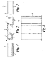
Figures 1 to 5 , amember 1 for a flooring system according to the invention comprises amale connector formation 2 and afemale connector formation 3 joined by a central section 4. Theconnectors member 1. The upper surfaces of the central section 4 andmale connector 2 define asupport surface 5. - The
member 1 is a single component of uniform cross-section extruded from thermoplastics, for example a high-density polyethylene or polypropylene or deformable polyvinyl chloride. Themember 1 is formed by cutting an extrusion of the appropriate section to any desired length. - The thermoplastics material of the
member 1 provides themember 1 with the required strength and rigidity to withstand the loads applied to the support surface in use without buckling while providing a small degree of flexibility due to the elasticity of the material as described later. In this embodiment, all the walls of themember 1 have a uniform thickness of 5mm and thetop surface 5 has a total width of 10cm. It will be understood that the dimensions may be altered depending on the materials and intended application of themember 1. - The
male connector 2 is a hollow rail of trapezium cross-section having abase 6, anupper portion 7 and twoside walls 8 and 9 that join thebase 6 to theupper portion 7. Thebase 6 is wider than theupper portion 7 and thewalls 8 and 9 extend at an angle from thebase 6 of 75° to the horizontal.Corners base 6 andwalls corners - The
female connector 3 has abase 12 and two relatively convergingside walls Side wall 13 is joined to central section 4 andside wall 14 has a smaller height thanside wall 13. Theside walls channel 15 having an opening (mouth) 16 of reduced cross-section. Thechannel 15 andopening 16 extend along the entire length of themember 1.Openings member 1. - The side wall 9 of the
male connector 2,side wall 13 of thefemale connector 3 and a lower surface of the central section 4 define a furtherfemale connector formation 20 having a mouth of reduced width open to the underside of themember 1. - The
upper surface 5 may be knurled, for example with a roller, to provideanti-slip formations 19. It will be understood that other anti-slip formations could be used, for example grooves in thesurface 5 or raised areas projecting from thesurface 5. Alternatively or additionally, thesurface 5 may be provided with an anti-slip material or compound such as a thermoplastic elastomer (TPE) which may be co-extruded with themember 1. - The trapezium shape of the
male connector 2 is complementary to the dovetailed shape of thechannel 15 such that themale connector 2 of anothersimilar member 1 can be received in thechannel 15. As best shown inFigure 2 , the height of themale connector 2 is substantially the same as the depth of thechannel 15 and the height of theouter wall 14 of thefemale connector 3 is less than theinner wall 13 by an amount substantially equal to the thickness of the centre section 4. Accordingly, theupper surfaces 5 ofadjacent members 1 are substantially co-planar when themale connector 2 of onemember 1 is received in thefemale connector 3 of anadjacent member 1. - The
male connector 2 of onemember 1 can be inserted in thechannel 15 of anothermember 1 either by sliding themale connector 2 into thechannel 15 through one of theopenings male connector 2 into thechannel 15 from above through theopening 16. To insert themale connector 2 into thechannel 15 by force-fitting, themale connector 2 is inserted into thechannel 15 in a direction substantially perpendicular to the plane of theupper surface 5. The width of theopening 16 is smaller than the width of thebase 6 of the male connector so that insertion of themale connector 2 into thechannel 15 throughopening 16 deflects theside wall 14 outwardly to allow themale connector 2 to enter thechannel 15. Therounded corners male connector 2 in thechannel 15. In particular, the rounded corners and the elasticity of thesidewall 14 allows themale connector 2 to be snapped into thechannel 15. On completion of insertion of themale connector 2 in thechannel 15, thesidewall 14 returns towards its original position. - A number of
members 1 are shown interlocked together inFigure 6 . Themale connector 2 of eachmember 1 is retained in thechannel 15 of anotheradjacent member 1 by the co-operating shape of theconnector formations upper surfaces 5 of theflooring members 1 co-operate to provide a continuous,planar support surface 21. Movement of themembers 1 relative to each other is minimised as the male andfemale connectors male connector 2 in thechannel 15. In addition, the arrangement of the male andfemale connectors support surface 21 maintains the engagement of theconnectors - Similarly to assembly, the members can be disassembled either by sliding the
male connector 2 from thechannel 15 throughopenings male connector 2 from thechannel 15 throughopening 16 by applying an upwards force to themember 1 at one end sufficient to deflect thesidewall 14 outwardly so that themale connector 2 can pass though the opening. - Now referring to
Figures 7 and8 , two different arrangements for assembling a flooring system comprising a plurality themembers 1 to form raised flooring are shown. - In
Figure 7 ,members 1 are arranged to be aligned end to end and are connected to each other by engagement withadjacent members 1 offset from the members by half the member's length. The members 1' at theedge 102 of the flooring can be cut to length to provide a straight edge finish to the flooring. - In
Figure 8 , a plurality ofmembers 1 are releasably connected together with their end faces aligned to form apanel 203. - Two
panels 203 may be interlocked together by interlocking rods 201 (shown by the dashed lines inFigure 8 ) received in aligned openings in a member of eachpanel 203 to interlock thepanels 203 together. Therods 201 relatively locatepanels 203 so that the ends of themembers 1 in onepanel 203 abut the ends ofmembers 1 in theother panel 203. One or moreconnecting rods 201 may be used to interconnect thepanels 203 together. Usually more than onerod 201 will be used. The connecting rod(s) 201 can be made of any suitable material including plastics and metals. - Alternatively, two
panels 203 may be interlocked together by anothermember 1" (shown by dashed lines inFigure 8 ). Themember 1" is reversed with itsfemale connector 3 received in the furtherfemale connector 20 of two upwardly facingmembers 1 and itsmale connector 2 located in a furtherfemale connector 20 of another two upwardly facingmembers 1. - Referring now to
Figures 9 and10 , there is shown another arrangement for assembling a flooring system in which aconnector strip 304 is arranged to join twopanels 303a, 303b. - Each
panel 303a, 303b is of rectangular shape made up of a plurality ofmembers 1 releasably connected together. Eachmember 1 is of uniform length and thepanel 303a,303b is built to the desired width by joining an appropriate number of members side-by-side. In this embodiment, themembers 1 are 5 metres long. This is a convenient length to transport, store and handle but it will be understood this is not essential and the length of themembers 1 may be chosen according to the intended application. - The
panels 303a, 303b are laid end-to-end and theconnector strip 304 is placed between and covers the adjacent ends of thepanels 303a,303b. As best shown inFigure 10 , theconnector strip 304 comprises acover member 304a and abase member 304b. - The
cover member 304a is of generally T-section with a central,longitudinal flange 304a' on the underside terminating in ahead 304a". Thebase member 304b has a central,longitudinal channel 304b' with relativelydivergent sidewalls 304b" extending from anannular socket 304b"'. - The
cover member 304a is releasably connectable to thebase member 304b by inserting theflange 304a' into thechannel 304b' until thehead 304a" is received and retained in thesocket 304b"'. The assembly of thecover member 304a andbase member 304b provides a pair of channels 305,306 separated by acentral web 307. - The
base member 304b may be positioned between the adjacent ends of adjoining panels and thecover member 304a secured to thebase member 304b to overlie and conceal the ends of the panels within the channels 305,306. Each channel 305,306 has a depth sufficient to leave aclearance gap 308 between the end of thepanel 303a,303b and theweb 307 such that thermal expansion/contraction of themembers 1 can be accommodated without exposing the ends of thepanels 303a,303b and without the floor buckling. In this way, theconnector strip 304 provides a neat finish betweenadjacent panels 303a,303b under all conditions and assists in locating and maintaining thepanels 303a,303b in the assembled condition. - The
cover member 304a andbase member 304b of theconnector strip 304 may be made of plastics, for example thermoplastic elastomer similar to themembers 1, by extrusion or moulding. Where themembers connector strip 304 may extend the full width of the flooring system with one or more panels being received in the channels 305,306 on each side. - The
connector strip 304 or at least thecover member 304a may be of same colour as themembers 1 or a different colour and may have similar properties, for example fire resistance, UV resistance etc. Theweb 307 may be adapted to allow air and/or liquid to pass through theweb 307 betweenpanels 303a, 303b. For example, theflange 304a' may be provided with apertures (not shown) at spaced intervals along the length. - It will be understood that the two-part construction allows the floor to be laid with the base member(s) 304b in position and then attaching the cover member(s) 304a to conceal the ends of the
panel members 1. Also the cover member(s) 304a can be detached leaving the base member(s) 304b in place if access to any of thepanels 1 is required, for example to remove/replace a damaged panel orpanel member 1. - It will also be understood that the shape and configuration of the
cover member 304a andbase member 304b may be altered as may the releasable connection for securing the members together. In a modification, not shown, theconnector strip 304 may be formed in one piece, for example by extrusion. - Referring now to
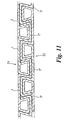
Figures 11 and12 , a flooring system assembled to provide both upwardly and downwardly facing, planar surfaces, is shown. In this arrangement, a plurality of upwardly facingmembers 1 interlocked together is releasably attached to a plurality of reversed, downwardly facingmembers 1" interlocked together. The complimentary shape of themembers female connector 2 of eachmember female connector 20 of an oppositely orientatedmember 1" or 1 respectively to attach themembers - Each further
female connector 20 of amember side wall 14 of another similarly orientatedmember female connector 3 of a oppositely orientatedmember female connector 3 and theside wall 14 is larger than the cross-section of the mouth of the furtherfemale connector 20. Accordingly, the rigidity of the thermoplastic material that forms themembers 1 prevents thefemale connector 3 andside wall 14 from coming out thefemale connector 20 during use of the flooring system. - The
surface 5 ofmembers 1 provides an upwardly facingplanar surface 21 andsurface 5 of reversedmembers 1" provide a downwardly facingsurface 22. A flooring system assembled in this manner is particularly suitable for use on soft ground as the loads supported on the flooring are distributed substantially evenly across the soft ground on which the flooring is assembled. A flooring system assembled according to this embodiment has increased strength over other embodiments without significantly increasing the total thickness of the flooring. This flooring system is suitable for supporting heavy loads, such as vehicles. It will be understood that downwardly facingmembers 1" can also be used in combination with a flooring system assembled according to any ofFigures 7 to 10 . - The flooring system is advantageous as the
male connector 2 can be inserted into thechannel 15 either throughopenings connectors male connector 2 intochannel 15 through theopening 16. This simplifies assembly of the flooring system by allowing themembers 1 to be attached together from above as well as from the ends. In this way, the flooring can be easily assembled in enclosed spaces where there may not be enough room to attach themembers 1 together by slide fitting. - Furthermore, movement of the assembled flooring system is minimised by the rigidity of the
members 1, which reduces flexing of themembers 1, and the non-circular complimentary shape of theconnector members 1, which minimises rotation of themale connector 2 in thechannel 15. - Moreover, only a single component having a uniform cross-section throughout its length is required for assembly of a flooring system according to the invention. As a result, manufacture of the
member 1 is simple reducing production costs. Also, a plurality ofmembers 1 can be stacked reducing the space required for storage and transportation providing further potential cost and logistical benefits. - Additionally, all the
members 1 are the same and anymember 1 can be attached to anyother member 1 so that assembly of the flooring system is simplified. In particular, special tools and skills are not required to assemble the flooring system and additional parts may also not be required providing further cost savings.. - A further advantage of the flooring system is that it can be assembled in a number of different arrangements. Accordingly, the flooring system can be adapted to many different uses. In particular, because the flooring system can be assembled to have a planar, downwardly facing surface the flooring system is suitable for use on soft ground.
- In an alternative embodiment shown in
Figure 13 , a flooring system comprises, twodifferent members 401, 401', onemember 401 having twofemale connectors 3 and the other member 401' having twomale connectors 2. Assembly of the male andfemale connectors - It will be apparent to those skilled in the art that the invention is not limited to the embodiments above-described and that various modifications can be made without departing from the concept or principle described in the dependent claims of a floor system comprising interlocking members releasably connected together by snap fit.
Claims (12)
- A flooring system comprising a plurality of elongate members (1) releasably attached together by co-operating male and female connector formations (2;3) extending along side edges of adjacent members (1), upper surfaces of the members (1) co-operating to provide a support surface (5), wherein the male connector formations (2) comprise a base (6) and two side walls (8,9), and the female connector formations (3) comprise a channel (15) opening to the upper surface for receiving the male connector formation (2), the channel (15) is of complementary shape to the male connector formation (2) the channel (15) has a base (12) and two side walls (13,14) that define an opening (16), and a side wall (14) of the channel (15) is capable of elastically deflecting so that the male connector formation (2) can be inserted into the channel (15) through the opening (16), and the side wall (14) returning towards its original position so that the male connector formation (2) is retained in the channel (15) by the co-operating shape of the connector formations (2;3) characterised in that the two side walls of the channel are relatively converging such that the opening is of reduced cross-section relative to the base (6) of the male connector formation (2).
- A flooring system according to claim 1 wherein, the male connector formation (2) comprises a downwardly extending rail that is inserted into the channel (15) of the female connector formation (3) in a direction perpendicular to the plane of the upper surface (5).
- A flooring system according to claim 2 wherein, the channel (15) of the female connector formation (3) and the rail of the male connector formation (2) are of complimentary non-circular cross-sections so that rotation of the rail in the channel (15) is prevented, for example the channel (15) is of dove-tail shape and the rail is of trapezium shape.
- A flooring system according to any preceding claim wherein the base (6) of the male connector formation (2) is joined to side walls (8,9) by radiused corners (10,11) that assist insertion of the male connector formation (2) into the channel (15) of the female connector formation (3).
- A flooring system according to any preceding claim wherein, when the members (1) are releasably attached together, the upper surfaces of the members that co-operate to form the support surface (5) are planar with each other and co-operate to provide a substantially continuous, planar support surface.
- A flooring system according to any preceding claim wherein, the members (1) are formed of plastics, for example thermoplastics selected from the group comprising polyethylene, high density polyethylene, polypropylene, deformable polyvinyl chloride and acetals, and are optionally fire resistant or treated to have an increased fire resistance.
- A flooring system according to any preceding claim wherein, each member (1) has a first side edge with a male connector formation (2) and a second side edge with a female connector formation (3).
- A flooring system according to any preceding claim wherein each member (1;1 ") has a pair of connector formations (2;3) extending along first and second side edges that define a further female connector formation (20) comprising a channel open to the underside of the member (1;1"), and the further female connector formation (20) can receive the female connector formation (3) on the side edge of another member (1;1") which has been inverted (reversed) so that, when connected, the members (1;1") provide upwardly and downwardly facing, planar support surfaces (21;22).
- A flooring system according to any preceding claim wherein the members (1) have walls of uniform thickness and are of uniform cross-section throughout their length.
- A flooring system according to any preceding claim wherein a plurality of members (1) are releasably connected together side-by-by side to form a rectangular panel (303), and a plurality of panels (303) are arranged end-to-end and/or side-by side with a connector strip (304) between the ends of adjoining panels (303a;303b) to provide an expansion gap such that any change in length of the members (1) due to thermal expansion/contraction can be accommodated.
- A method of assembling a flooring system according to any one of the preceding claims comprising the steps of releasably attaching two or more members (1) by inserting the male connector formation (2) of one member (1) into the channel (15) of the female connector (3) of another member (1), the direction of insertion being substantially perpendicular to the plane of the upper surface of the another member (1).
- A method according to claim 11 wherein, a first plurality of members (1) are assembled to have upwardly facing planar surfaces (21) and a second plurality of members (1") are reversed to have downwardly facing planar surfaces (22), the first and second plurality of members (1;1") being releasably attached to each other by co-operating connector formations (20;3) of the first and second plurality of members (1;1").
Applications Claiming Priority (3)
| Application Number | Priority Date | Filing Date | Title |
|---|---|---|---|
| GB0303136 | 2003-02-12 | ||
| GBGB0303136.6A GB0303136D0 (en) | 2003-02-12 | 2003-02-12 | Improvements in or relating to flooring systems |
| PCT/GB2004/000551 WO2004072406A1 (en) | 2003-02-12 | 2004-02-12 | Improvements in or relating to flooring systems |
Publications (2)
| Publication Number | Publication Date |
|---|---|
| EP1597445A1 EP1597445A1 (en) | 2005-11-23 |
| EP1597445B1 true EP1597445B1 (en) | 2012-06-27 |
Family
ID=9952837
Family Applications (1)
| Application Number | Title | Priority Date | Filing Date |
|---|---|---|---|
| EP04710435A Expired - Lifetime EP1597445B1 (en) | 2003-02-12 | 2004-02-12 | Flooring systems |
Country Status (6)
| Country | Link |
|---|---|
| US (1) | US7748176B2 (en) |
| EP (1) | EP1597445B1 (en) |
| AU (1) | AU2004211516B2 (en) |
| GB (1) | GB0303136D0 (en) |
| NZ (1) | NZ542257A (en) |
| WO (1) | WO2004072406A1 (en) |
Families Citing this family (39)
| Publication number | Priority date | Publication date | Assignee | Title |
|---|---|---|---|---|
| US7748177B2 (en) | 2004-02-25 | 2010-07-06 | Connor Sport Court International, Inc. | Modular tile with controlled deflection |
| US8407951B2 (en) | 2004-10-06 | 2013-04-02 | Connor Sport Court International, Llc | Modular synthetic floor tile configured for enhanced performance |
| US20090235605A1 (en) * | 2004-10-06 | 2009-09-24 | Thayne Haney | Method of Making A Modular Synthetic Floor Tile Configured For Enhanced Performance |
| US8397466B2 (en) | 2004-10-06 | 2013-03-19 | Connor Sport Court International, Llc | Tile with multiple-level surface |
| DK1936068T3 (en) | 2004-10-22 | 2012-03-19 | Vaelinge Innovation Ab | Method of providing floor panels with a mechanical locking system |
| US7841144B2 (en) | 2005-03-30 | 2010-11-30 | Valinge Innovation Ab | Mechanical locking system for panels and method of installing same |
| DE202004021674U1 (en) * | 2004-10-23 | 2010-06-10 | Kreusel, Ulrich | Cover for an area of balconies, floors, roofs or facades |
| USD656250S1 (en) | 2005-03-11 | 2012-03-20 | Connor Sport Court International, Llc | Tile with wide mouth coupling |
| US8061104B2 (en) | 2005-05-20 | 2011-11-22 | Valinge Innovation Ab | Mechanical locking system for floor panels |
| DE102006011887A1 (en) * | 2006-01-13 | 2007-07-19 | Akzenta Paneele + Profile Gmbh | Blocking element, panel with separate blocking element, method of installing a panel covering of panels with blocking elements, and method and device for pre-assembling a blocking element on a panel |
| US7490443B1 (en) * | 2006-03-01 | 2009-02-17 | Bike Track, Inc. | Modular flooring system |
| US7900416B1 (en) | 2006-03-30 | 2011-03-08 | Connor Sport Court International, Inc. | Floor tile with load bearing lattice |
| SE533410C2 (en) | 2006-07-11 | 2010-09-14 | Vaelinge Innovation Ab | Floor panels with mechanical locking systems with a flexible and slidable tongue as well as heavy therefore |
| US8025240B2 (en) * | 2006-10-19 | 2011-09-27 | Keller Komfort Radiant Systems, Inc. | Radiant heat flooring system |
| US8689512B2 (en) | 2006-11-15 | 2014-04-08 | Valinge Innovation Ab | Mechanical locking of floor panels with vertical folding |
| US11725394B2 (en) | 2006-11-15 | 2023-08-15 | Välinge Innovation AB | Mechanical locking of floor panels with vertical folding |
| SE531111C2 (en) | 2006-12-08 | 2008-12-23 | Vaelinge Innovation Ab | Mechanical locking of floor panels |
| US7992623B2 (en) | 2007-01-10 | 2011-08-09 | Keller Komfort Radiant Systems, Inc. | Radiant heat wall covering system |
| GB2468541A (en) * | 2009-03-13 | 2010-09-15 | David Vincent Byrne | Road hole cover |
| CN201411875Y (en) * | 2009-06-11 | 2010-02-24 | 李新发 | Keel with heat-transfer function |
| WO2011090499A1 (en) | 2010-01-22 | 2011-07-28 | Connor Sport Court International, Inc. | Modular sub-flooring system |
| US8881482B2 (en) | 2010-01-22 | 2014-11-11 | Connor Sport Court International, Llc | Modular flooring system |
| US8505256B2 (en) | 2010-01-29 | 2013-08-13 | Connor Sport Court International, Llc | Synthetic floor tile having partially-compliant support structure |
| US8806832B2 (en) | 2011-03-18 | 2014-08-19 | Inotec Global Limited | Vertical joint system and associated surface covering system |
| MY167150A (en) * | 2011-03-18 | 2018-08-13 | Inotec Int Pty Ltd | Vertical joint system and associated surface covering system |
| US9725912B2 (en) | 2011-07-11 | 2017-08-08 | Ceraloc Innovation Ab | Mechanical locking system for floor panels |
| US8650826B2 (en) * | 2011-07-19 | 2014-02-18 | Valinge Flooring Technology Ab | Mechanical locking system for floor panels |
| US8857126B2 (en) | 2011-08-15 | 2014-10-14 | Valinge Flooring Technology Ab | Mechanical locking system for floor panels |
| US9394698B2 (en) | 2012-02-23 | 2016-07-19 | Admiral Composite Technologies, Inc. | Deck system and components |
| US10760283B2 (en) | 2012-02-23 | 2020-09-01 | Admiral Composite Technologies, Inc. | Deck system and components |
| US9353533B2 (en) | 2012-02-23 | 2016-05-31 | Admiral Composite Technologies, Inc. | Deck system components |
| ES2759424T3 (en) | 2013-06-27 | 2020-05-11 | Vaelinge Innovation Ab | Construction panel with a mechanical locking system |
| EP3094670A1 (en) * | 2014-01-13 | 2016-11-23 | Greenfiber Tech, Lda. | Composite material and modular covering |
| US10246883B2 (en) | 2014-05-14 | 2019-04-02 | Valinge Innovation Ab | Building panel with a mechanical locking system |
| US10138636B2 (en) | 2014-11-27 | 2018-11-27 | Valinge Innovation Ab | Mechanical locking system for floor panels |
| US20180010344A1 (en) * | 2016-07-05 | 2018-01-11 | Matthew Thomas McClure | Modular extruded aluminum deck assembly |
| CA3125895A1 (en) | 2019-01-10 | 2020-07-16 | Valinge Innovation Ab | Set of panels that can be vertically unlocked, a method and a device therefore |
| CN110284394A (en) * | 2019-07-24 | 2019-09-27 | 山西省工业设备安装集团有限公司 | Coil assembled temporary road |
| US11819122B2 (en) * | 2019-12-13 | 2023-11-21 | James Tarpey | Load distributing deck insert |
Family Cites Families (18)
| Publication number | Priority date | Publication date | Assignee | Title |
|---|---|---|---|---|
| CH345451A (en) | 1956-06-27 | 1960-03-31 | Piodi Roberto | Rubber floor or similar material |
| US3110371A (en) * | 1959-09-03 | 1963-11-12 | Reynolds Metals Co | Metallic structural units |
| CH399702A (en) | 1962-11-16 | 1965-09-30 | Jansen & Co Ag | Prefabricated construction board |
| US3385182A (en) * | 1965-09-27 | 1968-05-28 | Harvey Aluminum Inc | Interlocking device for load bearing surfaces such as aircraft landing mats |
| US3959830A (en) * | 1975-04-28 | 1976-06-01 | Kdi Sylvan Pools, Inc. | Swimming pool |
| IL89005A (en) * | 1989-01-19 | 1991-11-21 | Polygal | Lightweight construction panels with interconnectable edges |
| CA2089025A1 (en) * | 1993-02-08 | 1994-08-09 | Vittorio De Zen | Molded cladding for building structures |
| USD366943S (en) * | 1994-09-21 | 1996-02-06 | Extrutech Plastics, Inc. | Extruded hollow panel |
| US5836128A (en) * | 1996-11-21 | 1998-11-17 | Crane Plastics Company Limited Partnership | Deck plank |
| US5797237A (en) * | 1997-02-28 | 1998-08-25 | Standard Plywoods, Incorporated | Flooring system |
| US6295778B1 (en) * | 1998-08-18 | 2001-10-02 | Crane Products Ltd. | Modular building structures comprised of extruded components |
| US6324796B1 (en) * | 2000-04-10 | 2001-12-04 | Homeland Vinyl Products, Inc. | Modular decking planks |
| US6729097B2 (en) * | 2000-10-12 | 2004-05-04 | Armstrong World Industries, Inc. | Hollow building panel having an angled support member and method of making same |
| US6637163B2 (en) * | 2001-07-25 | 2003-10-28 | Gt Plastics Inc. | Decking |
| US6931803B1 (en) * | 2002-03-08 | 2005-08-23 | Gary Davis | Modular building system |
| US6739106B2 (en) * | 2002-09-12 | 2004-05-25 | Royal Group Technologies Limited | Reversible plastic building board with different colored sides |
| USD485621S1 (en) * | 2003-02-24 | 2004-01-20 | Douglas O. Deel | Decking member |
| US7047697B1 (en) * | 2003-11-25 | 2006-05-23 | Homeland Vinyl Products, Inc. | Modular decking planks |
-
2003
- 2003-02-12 GB GBGB0303136.6A patent/GB0303136D0/en not_active Ceased
-
2004
- 2004-02-12 WO PCT/GB2004/000551 patent/WO2004072406A1/en active Application Filing
- 2004-02-12 AU AU2004211516A patent/AU2004211516B2/en not_active Ceased
- 2004-02-12 EP EP04710435A patent/EP1597445B1/en not_active Expired - Lifetime
- 2004-02-12 US US10/545,367 patent/US7748176B2/en not_active Expired - Fee Related
- 2004-02-12 NZ NZ542257A patent/NZ542257A/en not_active IP Right Cessation
Also Published As
| Publication number | Publication date |
|---|---|
| US7748176B2 (en) | 2010-07-06 |
| US20060080909A1 (en) | 2006-04-20 |
| GB0303136D0 (en) | 2003-03-19 |
| EP1597445A1 (en) | 2005-11-23 |
| AU2004211516B2 (en) | 2010-04-22 |
| WO2004072406A1 (en) | 2004-08-26 |
| AU2004211516A1 (en) | 2004-08-26 |
| NZ542257A (en) | 2007-01-26 |
Similar Documents
| Publication | Publication Date | Title |
|---|---|---|
| EP1597445B1 (en) | Flooring systems | |
| US6668514B2 (en) | Apparatus and method for connecting adjacent panels | |
| US5295341A (en) | Snap-together flooring system | |
| US5428933A (en) | Insulating construction panel or block | |
| US4907767A (en) | Stackable modular duct assemblies | |
| US5737893A (en) | Panel construction and connection system | |
| US5988599A (en) | Fence system | |
| US8322102B2 (en) | Wall panel system | |
| US7703248B2 (en) | Hollow interconnecting panels as lost formwork | |
| AU2007263407C1 (en) | Building structures and components therefor | |
| US7877936B2 (en) | Plastic utility shed roof system | |
| US20040036064A1 (en) | Extruded fence post and rail system | |
| US20060010804A1 (en) | Modular frame area floor covering | |
| US8132776B2 (en) | Sideform system | |
| US5542787A (en) | Extruded landscape timber modules | |
| US20020139070A1 (en) | Floor mats using rigid rails | |
| WO2005118273A1 (en) | Modular frame area floor covering | |
| EP0169697B1 (en) | Jointing system | |
| US5794922A (en) | Fence slats with locking portions | |
| US6026625A (en) | Angular interlocking floor tile | |
| EP3091140B1 (en) | Deck system and components | |
| EP0955412A3 (en) | Sectional modular elements for making non-permanent floors | |
| CA2111917C (en) | Modular panel for right angle interconnection | |
| EP0333463A1 (en) | Panel edge strips | |
| CA2188858C (en) | Panel construction and connection system |
Legal Events
| Date | Code | Title | Description |
|---|---|---|---|
| PUAI | Public reference made under article 153(3) epc to a published international application that has entered the european phase |
Free format text: ORIGINAL CODE: 0009012 |
|
| 17P | Request for examination filed |
Effective date: 20050902 |
|
| AK | Designated contracting states |
Kind code of ref document: A1 Designated state(s): AT BE BG CH CY CZ DE DK EE ES FI FR GB GR HU IE IT LI LU MC NL PT RO SE SI SK TR |
|
| AX | Request for extension of the european patent |
Extension state: AL LT LV MK |
|
| DAX | Request for extension of the european patent (deleted) | ||
| 17Q | First examination report despatched |
Effective date: 20080331 |
|
| GRAP | Despatch of communication of intention to grant a patent |
Free format text: ORIGINAL CODE: EPIDOSNIGR1 |
|
| RIC1 | Information provided on ipc code assigned before grant |
Ipc: E04F 15/10 20060101AFI20101026BHEP Ipc: E04F 19/06 20060101ALI20101026BHEP Ipc: E01C 9/08 20060101ALI20101026BHEP Ipc: E01C 5/20 20060101ALI20101026BHEP |
|
| RTI1 | Title (correction) |
Free format text: FLOORING SYSTEMS |
|
| GRAS | Grant fee paid |
Free format text: ORIGINAL CODE: EPIDOSNIGR3 |
|
| GRAA | (expected) grant |
Free format text: ORIGINAL CODE: 0009210 |
|
| AK | Designated contracting states |
Kind code of ref document: B1 Designated state(s): AT BE BG CH CY CZ DE DK EE ES FI FR GB GR HU IE IT LI LU MC NL PT RO SE SI SK TR |
|
| REG | Reference to a national code |
Ref country code: GB Ref legal event code: FG4D |
|
| REG | Reference to a national code |
Ref country code: CH Ref legal event code: EP |
|
| REG | Reference to a national code |
Ref country code: AT Ref legal event code: REF Ref document number: 564345 Country of ref document: AT Kind code of ref document: T Effective date: 20120715 |
|
| REG | Reference to a national code |
Ref country code: IE Ref legal event code: FG4D |
|
| REG | Reference to a national code |
Ref country code: DE Ref legal event code: R096 Ref document number: 602004038362 Country of ref document: DE Effective date: 20120823 |
|
| PG25 | Lapsed in a contracting state [announced via postgrant information from national office to epo] |
Ref country code: SE Free format text: LAPSE BECAUSE OF FAILURE TO SUBMIT A TRANSLATION OF THE DESCRIPTION OR TO PAY THE FEE WITHIN THE PRESCRIBED TIME-LIMIT Effective date: 20120627 Ref country code: FI Free format text: LAPSE BECAUSE OF FAILURE TO SUBMIT A TRANSLATION OF THE DESCRIPTION OR TO PAY THE FEE WITHIN THE PRESCRIBED TIME-LIMIT Effective date: 20120627 |
|
| REG | Reference to a national code |
Ref country code: NL Ref legal event code: VDEP Effective date: 20120627 |
|
| REG | Reference to a national code |
Ref country code: AT Ref legal event code: MK05 Ref document number: 564345 Country of ref document: AT Kind code of ref document: T Effective date: 20120627 |
|
| PG25 | Lapsed in a contracting state [announced via postgrant information from national office to epo] |
Ref country code: SI Free format text: LAPSE BECAUSE OF FAILURE TO SUBMIT A TRANSLATION OF THE DESCRIPTION OR TO PAY THE FEE WITHIN THE PRESCRIBED TIME-LIMIT Effective date: 20120627 Ref country code: GR Free format text: LAPSE BECAUSE OF FAILURE TO SUBMIT A TRANSLATION OF THE DESCRIPTION OR TO PAY THE FEE WITHIN THE PRESCRIBED TIME-LIMIT Effective date: 20120928 |
|
| PG25 | Lapsed in a contracting state [announced via postgrant information from national office to epo] |
Ref country code: BE Free format text: LAPSE BECAUSE OF FAILURE TO SUBMIT A TRANSLATION OF THE DESCRIPTION OR TO PAY THE FEE WITHIN THE PRESCRIBED TIME-LIMIT Effective date: 20120627 Ref country code: SK Free format text: LAPSE BECAUSE OF FAILURE TO SUBMIT A TRANSLATION OF THE DESCRIPTION OR TO PAY THE FEE WITHIN THE PRESCRIBED TIME-LIMIT Effective date: 20120627 Ref country code: CZ Free format text: LAPSE BECAUSE OF FAILURE TO SUBMIT A TRANSLATION OF THE DESCRIPTION OR TO PAY THE FEE WITHIN THE PRESCRIBED TIME-LIMIT Effective date: 20120627 Ref country code: EE Free format text: LAPSE BECAUSE OF FAILURE TO SUBMIT A TRANSLATION OF THE DESCRIPTION OR TO PAY THE FEE WITHIN THE PRESCRIBED TIME-LIMIT Effective date: 20120627 Ref country code: CY Free format text: LAPSE BECAUSE OF FAILURE TO SUBMIT A TRANSLATION OF THE DESCRIPTION OR TO PAY THE FEE WITHIN THE PRESCRIBED TIME-LIMIT Effective date: 20120627 Ref country code: RO Free format text: LAPSE BECAUSE OF FAILURE TO SUBMIT A TRANSLATION OF THE DESCRIPTION OR TO PAY THE FEE WITHIN THE PRESCRIBED TIME-LIMIT Effective date: 20120627 Ref country code: AT Free format text: LAPSE BECAUSE OF FAILURE TO SUBMIT A TRANSLATION OF THE DESCRIPTION OR TO PAY THE FEE WITHIN THE PRESCRIBED TIME-LIMIT Effective date: 20120627 |
|
| PG25 | Lapsed in a contracting state [announced via postgrant information from national office to epo] |
Ref country code: PT Free format text: LAPSE BECAUSE OF FAILURE TO SUBMIT A TRANSLATION OF THE DESCRIPTION OR TO PAY THE FEE WITHIN THE PRESCRIBED TIME-LIMIT Effective date: 20121029 Ref country code: IT Free format text: LAPSE BECAUSE OF FAILURE TO SUBMIT A TRANSLATION OF THE DESCRIPTION OR TO PAY THE FEE WITHIN THE PRESCRIBED TIME-LIMIT Effective date: 20120627 |
|
| PG25 | Lapsed in a contracting state [announced via postgrant information from national office to epo] |
Ref country code: NL Free format text: LAPSE BECAUSE OF FAILURE TO SUBMIT A TRANSLATION OF THE DESCRIPTION OR TO PAY THE FEE WITHIN THE PRESCRIBED TIME-LIMIT Effective date: 20120627 |
|
| PG25 | Lapsed in a contracting state [announced via postgrant information from national office to epo] |
Ref country code: ES Free format text: LAPSE BECAUSE OF FAILURE TO SUBMIT A TRANSLATION OF THE DESCRIPTION OR TO PAY THE FEE WITHIN THE PRESCRIBED TIME-LIMIT Effective date: 20121008 Ref country code: DK Free format text: LAPSE BECAUSE OF FAILURE TO SUBMIT A TRANSLATION OF THE DESCRIPTION OR TO PAY THE FEE WITHIN THE PRESCRIBED TIME-LIMIT Effective date: 20120627 |
|
| PLBE | No opposition filed within time limit |
Free format text: ORIGINAL CODE: 0009261 |
|
| STAA | Information on the status of an ep patent application or granted ep patent |
Free format text: STATUS: NO OPPOSITION FILED WITHIN TIME LIMIT |
|
| 26N | No opposition filed |
Effective date: 20130328 |
|
| REG | Reference to a national code |
Ref country code: DE Ref legal event code: R097 Ref document number: 602004038362 Country of ref document: DE Effective date: 20130328 |
|
| PG25 | Lapsed in a contracting state [announced via postgrant information from national office to epo] |
Ref country code: BG Free format text: LAPSE BECAUSE OF FAILURE TO SUBMIT A TRANSLATION OF THE DESCRIPTION OR TO PAY THE FEE WITHIN THE PRESCRIBED TIME-LIMIT Effective date: 20120927 |
|
| PG25 | Lapsed in a contracting state [announced via postgrant information from national office to epo] |
Ref country code: MC Free format text: LAPSE BECAUSE OF NON-PAYMENT OF DUE FEES Effective date: 20130228 |
|
| REG | Reference to a national code |
Ref country code: IE Ref legal event code: MM4A |
|
| PG25 | Lapsed in a contracting state [announced via postgrant information from national office to epo] |
Ref country code: IE Free format text: LAPSE BECAUSE OF NON-PAYMENT OF DUE FEES Effective date: 20130212 |
|
| PG25 | Lapsed in a contracting state [announced via postgrant information from national office to epo] |
Ref country code: TR Free format text: LAPSE BECAUSE OF FAILURE TO SUBMIT A TRANSLATION OF THE DESCRIPTION OR TO PAY THE FEE WITHIN THE PRESCRIBED TIME-LIMIT Effective date: 20120627 |
|
| PG25 | Lapsed in a contracting state [announced via postgrant information from national office to epo] |
Ref country code: LU Free format text: LAPSE BECAUSE OF NON-PAYMENT OF DUE FEES Effective date: 20130212 Ref country code: HU Free format text: LAPSE BECAUSE OF FAILURE TO SUBMIT A TRANSLATION OF THE DESCRIPTION OR TO PAY THE FEE WITHIN THE PRESCRIBED TIME-LIMIT; INVALID AB INITIO Effective date: 20040212 |
|
| REG | Reference to a national code |
Ref country code: FR Ref legal event code: PLFP Year of fee payment: 13 |
|
| REG | Reference to a national code |
Ref country code: FR Ref legal event code: PLFP Year of fee payment: 14 |
|
| REG | Reference to a national code |
Ref country code: FR Ref legal event code: PLFP Year of fee payment: 15 |
|
| PGFP | Annual fee paid to national office [announced via postgrant information from national office to epo] |
Ref country code: CH Payment date: 20180227 Year of fee payment: 15 Ref country code: DE Payment date: 20180201 Year of fee payment: 15 |
|
| PGFP | Annual fee paid to national office [announced via postgrant information from national office to epo] |
Ref country code: FR Payment date: 20180219 Year of fee payment: 15 |
|
| REG | Reference to a national code |
Ref country code: DE Ref legal event code: R119 Ref document number: 602004038362 Country of ref document: DE |
|
| REG | Reference to a national code |
Ref country code: CH Ref legal event code: PL |
|
| PG25 | Lapsed in a contracting state [announced via postgrant information from national office to epo] |
Ref country code: LI Free format text: LAPSE BECAUSE OF NON-PAYMENT OF DUE FEES Effective date: 20190228 Ref country code: CH Free format text: LAPSE BECAUSE OF NON-PAYMENT OF DUE FEES Effective date: 20190228 |
|
| PG25 | Lapsed in a contracting state [announced via postgrant information from national office to epo] |
Ref country code: DE Free format text: LAPSE BECAUSE OF NON-PAYMENT OF DUE FEES Effective date: 20190903 |
|
| PG25 | Lapsed in a contracting state [announced via postgrant information from national office to epo] |
Ref country code: FR Free format text: LAPSE BECAUSE OF NON-PAYMENT OF DUE FEES Effective date: 20190228 |
|
| PGFP | Annual fee paid to national office [announced via postgrant information from national office to epo] |
Ref country code: GB Payment date: 20200825 Year of fee payment: 17 |
|
| GBPC | Gb: european patent ceased through non-payment of renewal fee |
Effective date: 20210212 |
|
| PG25 | Lapsed in a contracting state [announced via postgrant information from national office to epo] |
Ref country code: GB Free format text: LAPSE BECAUSE OF NON-PAYMENT OF DUE FEES Effective date: 20210212 |