EP1597429B1 - Fluid distributor - Google Patents
Fluid distributor Download PDFInfo
- Publication number
- EP1597429B1 EP1597429B1 EP04708759A EP04708759A EP1597429B1 EP 1597429 B1 EP1597429 B1 EP 1597429B1 EP 04708759 A EP04708759 A EP 04708759A EP 04708759 A EP04708759 A EP 04708759A EP 1597429 B1 EP1597429 B1 EP 1597429B1
- Authority
- EP
- European Patent Office
- Prior art keywords
- steam
- web
- porous metal
- housing
- fluid
- Prior art date
- Legal status (The legal status is an assumption and is not a legal conclusion. Google has not performed a legal analysis and makes no representation as to the accuracy of the status listed.)
- Expired - Fee Related
Links
- 239000012530 fluid Substances 0.000 title claims description 23
- 239000002184 metal Substances 0.000 claims abstract description 60
- 238000004891 communication Methods 0.000 claims description 18
- 239000000843 powder Substances 0.000 claims description 3
- 239000000725 suspension Substances 0.000 claims description 3
- 238000009826 distribution Methods 0.000 description 12
- 230000008878 coupling Effects 0.000 description 8
- 238000010168 coupling process Methods 0.000 description 8
- 238000005859 coupling reaction Methods 0.000 description 8
- XLYOFNOQVPJJNP-UHFFFAOYSA-N water Substances O XLYOFNOQVPJJNP-UHFFFAOYSA-N 0.000 description 5
- 238000004519 manufacturing process Methods 0.000 description 4
- 238000000034 method Methods 0.000 description 3
- 239000002245 particle Substances 0.000 description 3
- 238000003825 pressing Methods 0.000 description 3
- 239000007921 spray Substances 0.000 description 2
- 238000003490 calendering Methods 0.000 description 1
- 238000009833 condensation Methods 0.000 description 1
- 230000005494 condensation Effects 0.000 description 1
- 230000000694 effects Effects 0.000 description 1
- 239000007788 liquid Substances 0.000 description 1
- 238000012423 maintenance Methods 0.000 description 1
- 239000000203 mixture Substances 0.000 description 1
- 238000003908 quality control method Methods 0.000 description 1
- 230000001105 regulatory effect Effects 0.000 description 1
- 238000007789 sealing Methods 0.000 description 1
- 238000005507 spraying Methods 0.000 description 1
Images


Classifications
-
- D—TEXTILES; PAPER
- D21—PAPER-MAKING; PRODUCTION OF CELLULOSE
- D21F—PAPER-MAKING MACHINES; METHODS OF PRODUCING PAPER THEREON
- D21F7/00—Other details of machines for making continuous webs of paper
- D21F7/008—Steam showers
Definitions
- This invention relates to efficiently distributing a fluid to a web of a paper machine, and more specifically, to a steam distributor that can be used in steam showers to deliver steam with a predetermined mass profile.
- FIG. 1 shows a papermaking machine and four possible mounting locations for the steam showers.
- Steam is usually added before the press nips to increase the production with the effect of increasing the temperature of all of the moisture in the web.
- the added temperature makes the water removal by pressing much more effective.
- the moisture removed by pressing is much greater than the added moisture resulting from steam condensation.
- the web leaves the press nips and enters the dryer. A web with higher dryness at the end of pressing allows the dryer to run at a higher speed and hence results in increased paper production.
- Profiling steam showers work by selectively delivering steam to segments (or zones) of the web in the cross-machine (CD) direction to compensate an unfavorable moisture distribution in that direction.
- Existing profiling steam showers are constructed with an array of steam distributors along the CD direction.
- a single steam distributor is also used for non-profiling applications that delivers a constant pattern of steam across the CD direction.
- the steam distributor usually consists of a screen plate that is mounted nearby and facing the surface of the web to be steam treated. Traditionally, the screen plate has a number of orifices with a constant spacing along the CD direction through which steam impinges upon the moving web.
- the amount of steam passing through each steam distributor is adjustable by changing the steam pressure feeding the screen plate.
- Positioning or regulator-type actuator valves controlled by pneumatic signals generated remotely off the machine are usually employed to manipulate the steam' pressure within each steam distributor for profiling purpose.
- One of the parameters is the mass (moisture or heat) distribution within a single zone and the other is the coupling between adjacent zones.
- a flat moisture profile at reel could be achieved if the mass distribution is a perfect square in shape within a single zone and the coupling is zero between neighboring zones, as long as the zone size is small enough.
- the velocity profile and the mass profile of a single orifice jet both have a bell-shaped distribution.
- a single steam distributor consisting of a number of such orifices produces a wavy mass profile on the surface of the sheet.
- the magnitude of the fluctuation of the mass distribution is a function of several parameters including single jet mass distribution, orifice spacing and the distance between the orifices and the paper surface. Theoretically the smaller the orifice spacing the flatter the resulting mass profile, and the less the coupling between adjacent zones as a result of reduced sheet distance. However, smaller orifice spacing results in more orifices required In a single zone as well as smaller orifice diameter to maintain the flow rate and consequently higher cost for the screen plate, and the steam distributor or the steam shower.
- EP 1 081 278 A discloses a steam box (10) having an elongated steam-distribution chamber (11) with adjacent regulator chambers (15).
- a perforated screen (20) covers a side of the regulator chambers (15).
- EP1081278 does not disclose the size of the holes in the perforated screen (20) and does not disclose any details about the composition of the perforated screen (20).
- the steam distributor of the present invention consists of a steam distributing plate made from porous metal.
- the width of the porous metal plate represents the zone size of the steam shower in the CD direction.
- the steam flow rate passing through a single porous metal plate with a fixed zone size is determined by the media grade of the porous metal, the thickness and the length in the machine direction of the plate as well as the steam pressure feeding the porous metal plate.
- the porous metal plate is typically manufactured by preparing metal powders with a precisely controlled particle size based on the media grades produced. Powders with constant particle size are then compressed into a plate before being sintered. This procedure produces porous metal plates with uniform porosity and required bonds between the particles. The low cost and ready availability of the porous metal plates with different media grades make the steam distributor of the present invention practical yet affordable.
- a steam distributor for use with a machine that produces a web.
- the steam distributor comprises a steam housing having a steam inlet in sealed communication with the housing; and one or more porous metal plates mounted in the housing in an orientation to face the web when the steam distributor is mounted at a predetermined location on the web producing machine, each of the one or more porous metal plates forming a plurality of steam outlets which are in sealed communication with the steam housing.
- An apparatus for distributing a fluid for use with a machine that produces a web comprises a housing for the fluid having a fluid inlet in sealed communication with the housing; and one or more porous metal plates mounted in the housing in an orientation to face the web when the fluid distributing apparatus is mounted at a predetermined location on the web producing machine, each of the on or more porous metal plates having a plurality of said fluid outlets which are in sealed communication with the housing.
- a steam shower for use with a machine that produces a web comprises two or more steam housings, each of the two or more steam housings separated from an adjacent one of the two or more housings and having a steam inlet in sealed communication with an associated one of the two or more housings; and one or more porous metal plates mounted in the housing in an orientation to face the web when the steam shower is mounted at a predetermined location on the web producing machine, each of the one or more porous metal plates having a plurality of steam outlets which are in sealed communication with an associated one of the two or more steam housings.
- a machine for producing a web and one or more steam showers each mounted at an associated one of one or more predetermined locations along the web producing machine, each of the one or more steam showers comprising:
- FIG. 2 there is shown a schematic section view through an embodiment of the steam distributor 1 according to the present invention for delivering steam to the web 2 of a papermaking machine.
- the steam distributor 1 is mounted close to the paper web 2 that is to be steam treated by supports (not shown).
- the arrow 7 shows the machine direction (MD), that is, the moving direction of the web 2.
- the steam distributor 1 comprises a steam housing 4 and a steam inlet 9 that is in sealed communication with the steam housing 4.
- One or several pieces of porous metal plates 3 facing the web 2 at the bottom of the steam distributor 1 form the steam outlets of the housing 4.
- the steam outlets on the porous metal plate 3 are also in sealed communication with the steam housing 4.
- the porous metal plate 3 is placed parallel to the web of the paper sheet.
- the porous metal plate 3 is flat if the steam distributor 1 is mounted above a flat web.
- the porous metal plate 3 can also be formed into a curved metal sheet to match the curvature of the web 2 if the steam distributor 1 is mounted to face a roll.
- Arrow 6 shows the straight streamlines of the steam flow passing through the porous metal plate 3.
- the width of the porous plate 3 in the cross-machine direction defines a band on the web surface that is affected by the steam. This band could cover the whole web surface if a non-profiling steam shower is to be used.
- the width of the band in the CD direction defines the zone size. The size of a single zone can be arbitrary, however 2 inches (about 5 cm) to 6 inches (about 15 cm) are typical for existing profiling steam showers.
- the steam flow rate passing through the steam distributor 1 is determined by several properties of the porous plate 3 as well as the steam pressure in the steam housing 4.
- the influencing properties of the porous metal plate 3 include the length of the porous plate 3 in the machine direction, the media grade and the thickness of the porous plate 3.
- the variety in the selection of the porous metal plate 3 allows the users of the steam distributor 1 to design a steam shower that gives the best fit to their specific application.
- the application could be in the wet end (Location #1 and #2 in Figure 1 ) or in the dry end (Location #3 in Figure 1 , for example), or even in a finishing calender (Location #4 in Figure 1 ) of a paper making machine.
- the steam distributor 1 can deliver controllable steam flow to the web 2 by manipulating the steam pressure in the steam housing 4.
- An actuator valve 8 located between the inlet 9 and the steam housing 4 can be used to provide the required steam pressure in the steam housing 4.
- the inlet 9 is in sealed communication with a pressurized steam source (not shown) that is located off the paper-machine and readily available in any paper mill.
- the web 2 will receive no steam from the steam distributor 1 if the steam pressure in the steam housing 4 is zero. Increasing the steam pressure inside the housing 4 increases the steam flow passing through the porous metal plate 3 and consequently increases the amount of steam received by the moving web 2.
- the porous metal plate 3 can be considered as a conventional screen plate having thousands of thousands of micro-orifices aligned in both the cross-machine direction and the machine direction with spacing in the range of microns. The result is a flat mass or moisture or heat profile within the span (or zone) of the steam distributor.
- the flat steam distribution of the steam distributor 1 benefits all steam shower applications.
- Another benefit of the steam distributor 1 is the minimum coupling between neighboring distributors of a steam shower.
- the minimum coupling is a direct result of the almost perfect square-shaped steam mass profile generated by a single steam distributor 1.
- the result is the highest resolution achievable by a steam shower with a fixed zone size.
- Yet another benefit associated with the minimum coupling of the steam distributor 1 is the insensitivity of the steam distributor's distance to the web or sheet 2.
- Sheet distance is a sensitive parameter for conventional steam showers that require time-consuming on machine fine-tuning at start up. Inappropriate sheet distance of conventional steam showers causes streaking on the surface of the paper.
- the collimated beams of steam delivered by the steam distributor 1 can potentially eliminate the streaking without fine-tuning the sheet distance.
- the pressure drops through a conventional screen plate are less than a couple of kPa (PSI) in unit. Increased pressure drop in the conventional screen plate results in excessive steam velocity and consequently over-spray of the steam.
- PSD kPa
- the porous metal plate 3 of the steam distributor 1 allows the pressure drop to be much larger than that through a conventional screen plate thanks to the added frictions through the micro orifices in the porous plate 3.
- the efficient mixing between environment air and micro steam jets at the porous metal plate 3 during the distribution of the steam may also benefit the increased pressure drop. Larger pressure drops in steam distributor 1 provide a wider control range, as the flow rate passing through the steam distributor 1 is regulated by adjusting the pressure feeding the screen plate or the porous metal plate 3.
- the steam distributor 1 is not limited to the configuration of one porous metal plate 3 per distributor. It is possible to construct a steam shower with steam distributing zones that share a single piece of porous metal plate across the CD direction.
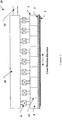
- FIG 3 shows a schematic steam shower 10 that is consisting of an array of the steam distributor 1 of the present invention across the machine direction.
- the steam housings 4 are separated by metal plate 12.
- Each steam distributor 1 has an actuator valve 8 that controls the steam pressure in the corresponding steam housing 4. All the steam distributors 1 share a common steam chamber 18, which is in sealed communication with a steam inlet 14.
- the steam inlet 14 is in sealed communication with a steam source (not shown) off the machine.
- the porous metal plate 3 in Figure 3 can be one single piece across the whole steam shower 10 to reduce the manufacturing and maintenance costs. In this case, sealing between adjacent steam housing 4 may be necessary.
- a porous metal plate 3 in Figure 3 with shapes other than a rectangle could be used to produce a desired mass profile in the CD direction.
- a single steam distributor 1 as shown in Figure 2 with a porous metal plate 3 cut into a special contour along the CD direction according to a measured profile of a selected paper property to be controlled could be used for profiling purposes.
- the measured profile can be a moisture profile, a gloss profile or any other profile that affects the quality of the paper products in the cross-machine direction. In this case, zone actuators and the conventional on-machine profiling are unnecessary. More importantly, a perfect flat moisture profile at the reel could be achieved as this custom designed steam distributor has infinite resolution.
- a variety of other arrangements can be devised which would operate on the same principles disclosed above.
- the steam distributor and the steam shower using the porous metal plate 3 are useful in many other applications.
- the present invention is appropriate where the need exists for a tailorable distribution of a fluid (steam, gas or liquid) to a surface of a medium.
- the distribution could be extremely uniform, or follow a predetermined profile as required.
- porous metal plate using the embodiment of Fig. 2 is a paper suspension device that supports the moving paper web without even touching the surface of the paper. This is especially useful for coated paper.
- element 9 is an inlet for compressed air. Air delivered through the porous metal plate forms a pressurized air cushion between the porous metal plate and the moving web. The air cushion serves as a medium for the contactless support to the moving web.
- FIG. 2 Yet another potential application of the porous metal plate using the embodiment of Fig. 2 is a highly efficient air curtain or air knife.
- Air curtains or air knifes are now widely used with water spray systems in papermaking machine to confine the spraying water droplets to the defined rewet area without causing problems to the papermaking process.
- Air curtains made of porous metal plates can be mounted very close to the moving web without interference to the process. Because the gap between the porous plates and the web sheet can be very small, the air that is required to curtain off water droplets is substantially reduced.
- element 9 is an inlet for compressed air.
Abstract
Description
- This invention relates to efficiently distributing a fluid to a web of a paper machine, and more specifically, to a steam distributor that can be used in steam showers to deliver steam with a predetermined mass profile.
- Steam showers are widely used in a papermaking machine for production gain and quality control.
Figure 1 shows a papermaking machine and four possible mounting locations for the steam showers. Steam is usually added before the press nips to increase the production with the effect of increasing the temperature of all of the moisture in the web. The added temperature makes the water removal by pressing much more effective. The moisture removed by pressing is much greater than the added moisture resulting from steam condensation. The web leaves the press nips and enters the dryer. A web with higher dryness at the end of pressing allows the dryer to run at a higher speed and hence results in increased paper production. - Steam is also added by using profiling steam showers to improve the paper quality such as moisture distribution across the paper. Profiling steam showers work by selectively delivering steam to segments (or zones) of the web in the cross-machine (CD) direction to compensate an unfavorable moisture distribution in that direction.
- It is well known that there are numerous influences on the paper machine that can cause a variation of the moisture content, especially in the CD direction. Wet edges and characteristic moisture profiles are common occurrences on paper machines. Profiling steam showers are also used for finishing purposes on calenders or supercalenders to improve paper smoothness, gloss and caliper etc.
- Existing profiling steam showers are constructed with an array of steam distributors along the CD direction. A single steam distributor is also used for non-profiling applications that delivers a constant pattern of steam across the CD direction. The steam distributor usually consists of a screen plate that is mounted nearby and facing the surface of the web to be steam treated. Traditionally, the screen plate has a number of orifices with a constant spacing along the CD direction through which steam impinges upon the moving web. The amount of steam passing through each steam distributor is adjustable by changing the steam pressure feeding the screen plate. Positioning or regulator-type actuator valves controlled by pneumatic signals generated remotely off the machine are usually employed to manipulate the steam' pressure within each steam distributor for profiling purpose.
- Uniformly distributing steam across the web of paper in a paper machine requires the steam distributing screen plate of a steam shower to have enough small orifices arranged tightly along the cross-machine (CD) direction. This is especially true for steam shower applications in the dryer end or finishing calendering where steam flow is very small. A wavy moisture profile in the CD direction of the paper resulting from steam treatment using conventional screen plates is a common phenomenon.
- There are two very important parameters for profiling steam showers. One of the parameters is the mass (moisture or heat) distribution within a single zone and the other is the coupling between adjacent zones.
- Ideally, a flat moisture profile at reel could be achieved if the mass distribution is a perfect square in shape within a single zone and the coupling is zero between neighboring zones, as long as the zone size is small enough. As is well known, the velocity profile and the mass profile of a single orifice jet both have a bell-shaped distribution. A single steam distributor consisting of a number of such orifices produces a wavy mass profile on the surface of the sheet. There is also a substantial coupling between adjacent distributors similar to the coupling between neighboring jets.
- The magnitude of the fluctuation of the mass distribution is a function of several parameters including single jet mass distribution, orifice spacing and the distance between the orifices and the paper surface. Theoretically the smaller the orifice spacing the flatter the resulting mass profile, and the less the coupling between adjacent zones as a result of reduced sheet distance. However, smaller orifice spacing results in more orifices required In a single zone as well as smaller orifice diameter to maintain the flow rate and consequently higher cost for the screen plate, and the steam distributor or the steam shower.
-
EP 1 081 278 AEP1081278 does not disclose the size of the holes in the perforated screen (20) and does not disclose any details about the composition of the perforated screen (20). - To overcome the shortcomings of conventional steam showers, a new steam distributing apparatus having the features of
claim 1 is disclosed. The steam distributor of the present invention consists of a steam distributing plate made from porous metal. The width of the porous metal plate represents the zone size of the steam shower in the CD direction. The steam flow rate passing through a single porous metal plate with a fixed zone size is determined by the media grade of the porous metal, the thickness and the length in the machine direction of the plate as well as the steam pressure feeding the porous metal plate. - The porous metal plate is typically manufactured by preparing metal powders with a precisely controlled particle size based on the media grades produced. Powders with constant particle size are then compressed into a plate before being sintered. This procedure produces porous metal plates with uniform porosity and required bonds between the particles. The low cost and ready availability of the porous metal plates with different media grades make the steam distributor of the present invention practical yet affordable.
- A steam distributor for use with a machine that produces a web. The steam distributor comprises a steam housing having a steam inlet in sealed communication with the housing; and one or more porous metal plates mounted in the housing in an orientation to face the web when the steam distributor is mounted at a predetermined location on the web producing machine, each of the one or more porous metal plates forming a plurality of steam outlets which are in sealed communication with the steam housing.
- An apparatus for distributing a fluid for use with a machine that produces a web. The apparatus comprises a housing for the fluid having a fluid inlet in sealed communication with the housing; and one or more porous metal plates mounted in the housing in an orientation to face the web when the fluid distributing apparatus is mounted at a predetermined location on the web producing machine, each of the on or more porous metal plates having a plurality of said fluid outlets which are in sealed communication with the housing.
- A steam shower for use with a machine that produces a web. The steam shower comprises two or more steam housings, each of the two or more steam housings separated from an adjacent one of the two or more housings and having a steam inlet in sealed communication with an associated one of the two or more housings; and one or more porous metal plates mounted in the housing in an orientation to face the web when the steam shower is mounted at a predetermined location on the web producing machine, each of the one or more porous metal plates having a plurality of steam outlets which are in sealed communication with an associated one of the two or more steam housings.
- In combination a machine for producing a web and one or more fluid distributors each mounted at an associated one of one or more predetermined locations along the web producing machine, each of the one or more fluid distributors comprising:
- a fluid housing having a fluid inlet in sealed communication with the housing; and
- one or more porous metal plates mounted in the housing in an orientation to face the web when each of the one or more fluid distributors is mounted at the associated one of the one or more predetermined locations, each of the one or more porous metal plates having a plurality of fluid outlets which are in sealed communication with the fluid housing.
- In combination a machine for producing a web and one or more steam showers each mounted at an associated one of one or more predetermined locations along the web producing machine, each of the one or more steam showers comprising:
- two or more steam housings, each of the two or more steam housings separated from an adjacent one of the two or more housings and having a steam inlet in sealed communication with an associated one of the two or more housings; and
- one or more porous metal plates mounted in the housing in an orientation to face the web when each of the one or more steam showers is mounted at the associated one of the one or more predetermined locations, each of the one or more porous metal plates having a plurality of steam outlets which are in sealed communication with an associated one of the two or more steam housings.
-
-
Fig. 1 shows a schematic for a papermaking machine and four well known locations for the steam showers of the present invention. -
Fig. 2 shows a schematic section view through an embodiment of the steam distributor of the present invention that can be used in steam showers. -
Fig. 3 shows a schematic view of an embodiment of the steam shower of the present invention. - Referring now to
Fig. 2 , there is shown a schematic section view through an embodiment of thesteam distributor 1 according to the present invention for delivering steam to theweb 2 of a papermaking machine. Thesteam distributor 1 is mounted close to thepaper web 2 that is to be steam treated by supports (not shown). Thearrow 7 shows the machine direction (MD), that is, the moving direction of theweb 2. - The
steam distributor 1 comprises asteam housing 4 and asteam inlet 9 that is in sealed communication with thesteam housing 4. One or several pieces ofporous metal plates 3 facing theweb 2 at the bottom of thesteam distributor 1 form the steam outlets of thehousing 4. The steam outlets on theporous metal plate 3 are also in sealed communication with thesteam housing 4. Preferably, theporous metal plate 3 is placed parallel to the web of the paper sheet. Theporous metal plate 3 is flat if thesteam distributor 1 is mounted above a flat web. Theporous metal plate 3 can also be formed into a curved metal sheet to match the curvature of theweb 2 if thesteam distributor 1 is mounted to face a roll.Arrow 6 shows the straight streamlines of the steam flow passing through theporous metal plate 3. - The width of the
porous plate 3 in the cross-machine direction defines a band on the web surface that is affected by the steam. This band could cover the whole web surface if a non-profiling steam shower is to be used. In the case of profiling steam showers, the width of the band in the CD direction defines the zone size. The size of a single zone can be arbitrary, however 2 inches (about 5 cm) to 6 inches (about 15 cm) are typical for existing profiling steam showers. - For a
steam distributor 1 with a fixed width of theporous metal plate 3, the steam flow rate passing through thesteam distributor 1 is determined by several properties of theporous plate 3 as well as the steam pressure in thesteam housing 4. The influencing properties of theporous metal plate 3 include the length of theporous plate 3 in the machine direction, the media grade and the thickness of theporous plate 3. The variety in the selection of theporous metal plate 3 allows the users of thesteam distributor 1 to design a steam shower that gives the best fit to their specific application. The application could be in the wet end (Location # 1 and #2 inFigure 1 ) or in the dry end (Location # 3 inFigure 1 , for example), or even in a finishing calender (Location # 4 inFigure 1 ) of a paper making machine. - After being mounted on the paper machine, the
steam distributor 1 can deliver controllable steam flow to theweb 2 by manipulating the steam pressure in thesteam housing 4. Anactuator valve 8 located between theinlet 9 and thesteam housing 4 can be used to provide the required steam pressure in thesteam housing 4. Theinlet 9 is in sealed communication with a pressurized steam source (not shown) that is located off the paper-machine and readily available in any paper mill. Theweb 2 will receive no steam from thesteam distributor 1 if the steam pressure in thesteam housing 4 is zero. Increasing the steam pressure inside thehousing 4 increases the steam flow passing through theporous metal plate 3 and consequently increases the amount of steam received by the movingweb 2. - One benefit of the
steam distributor 1 is that it delivers steam with extreme uniformity. Theporous metal plate 3 can be considered as a conventional screen plate having thousands of thousands of micro-orifices aligned in both the cross-machine direction and the machine direction with spacing in the range of microns. The result is a flat mass or moisture or heat profile within the span (or zone) of the steam distributor. The flat steam distribution of thesteam distributor 1 benefits all steam shower applications. - Another benefit of the
steam distributor 1 is the minimum coupling between neighboring distributors of a steam shower. The minimum coupling is a direct result of the almost perfect square-shaped steam mass profile generated by asingle steam distributor 1. The result is the highest resolution achievable by a steam shower with a fixed zone size. - Yet another benefit associated with the minimum coupling of the
steam distributor 1 is the insensitivity of the steam distributor's distance to the web orsheet 2. Sheet distance is a sensitive parameter for conventional steam showers that require time-consuming on machine fine-tuning at start up. Inappropriate sheet distance of conventional steam showers causes streaking on the surface of the paper. The collimated beams of steam delivered by thesteam distributor 1 can potentially eliminate the streaking without fine-tuning the sheet distance. - Yet another benefit of the
steam distributor 1 is its increased controllability. The pressure drops through a conventional screen plate are less than a couple of kPa (PSI) in unit. Increased pressure drop in the conventional screen plate results in excessive steam velocity and consequently over-spray of the steam. Theporous metal plate 3 of thesteam distributor 1 allows the pressure drop to be much larger than that through a conventional screen plate thanks to the added frictions through the micro orifices in theporous plate 3. The efficient mixing between environment air and micro steam jets at theporous metal plate 3 during the distribution of the steam may also benefit the increased pressure drop. Larger pressure drops insteam distributor 1 provide a wider control range, as the flow rate passing through thesteam distributor 1 is regulated by adjusting the pressure feeding the screen plate or theporous metal plate 3. - The
steam distributor 1 is not limited to the configuration of oneporous metal plate 3 per distributor. It is possible to construct a steam shower with steam distributing zones that share a single piece of porous metal plate across the CD direction. -
Figure 3 shows aschematic steam shower 10 that is consisting of an array of thesteam distributor 1 of the present invention across the machine direction. Thesteam housings 4 are separated bymetal plate 12. Eachsteam distributor 1 has anactuator valve 8 that controls the steam pressure in thecorresponding steam housing 4. All thesteam distributors 1 share acommon steam chamber 18, which is in sealed communication with asteam inlet 14. Thesteam inlet 14 is in sealed communication with a steam source (not shown) off the machine. - Pressurized steam from the steam source flows into the
common chamber 18 through theinlet 14. Based on the measured profile near the reel,steam actuators 8 manipulate the steam pressure in eachindividual steam housing 4, such that the steam flow through eachsteam distributor 1 is exactly the required amount to achieve a flat profile at the reel. - The
porous metal plate 3 inFigure 3 can be one single piece across thewhole steam shower 10 to reduce the manufacturing and maintenance costs. In this case, sealing betweenadjacent steam housing 4 may be necessary. - A
porous metal plate 3 inFigure 3 with shapes other than a rectangle could be used to produce a desired mass profile in the CD direction. Asingle steam distributor 1 as shown inFigure 2 with aporous metal plate 3 cut into a special contour along the CD direction according to a measured profile of a selected paper property to be controlled could be used for profiling purposes. The measured profile can be a moisture profile, a gloss profile or any other profile that affects the quality of the paper products in the cross-machine direction. In this case, zone actuators and the conventional on-machine profiling are unnecessary. More importantly, a perfect flat moisture profile at the reel could be achieved as this custom designed steam distributor has infinite resolution. A variety of other arrangements can be devised which would operate on the same principles disclosed above. - It will be clear to a person skilled in the art that the steam distributor and the steam shower using the
porous metal plate 3 are useful in many other applications. The present invention is appropriate where the need exists for a tailorable distribution of a fluid (steam, gas or liquid) to a surface of a medium. The distribution could be extremely uniform, or follow a predetermined profile as required. - Another potential use of the porous metal plate using the embodiment of
Fig. 2 is a paper suspension device that supports the moving paper web without even touching the surface of the paper. This is especially useful for coated paper. As can be appreciated when the embodiment ofFig. 2 is used for a paper suspension device,element 9 is an inlet for compressed air. Air delivered through the porous metal plate forms a pressurized air cushion between the porous metal plate and the moving web. The air cushion serves as a medium for the contactless support to the moving web. - Yet another potential application of the porous metal plate using the embodiment of
Fig. 2 is a highly efficient air curtain or air knife. Air curtains or air knifes are now widely used with water spray systems in papermaking machine to confine the spraying water droplets to the defined rewet area without causing problems to the papermaking process. Air curtains made of porous metal plates can be mounted very close to the moving web without interference to the process. Because the gap between the porous plates and the web sheet can be very small, the air that is required to curtain off water droplets is substantially reduced. By using a porous metal air curtain, it is possible to retain water droplets within the defined rewet area with sufficiently less air consumption. As can be appreciated when the embodiment ofFig. 2 is used for an air curtain or air knife,element 9 is an inlet for compressed air. - It is to be understood that the description of the preferred embodiment (s) is (are) intended to be only illustrative, rather than exhaustive, of the present invention.
Claims (11)
- An apparatus (1, 10) for distributing a fluid for use with a machine that produces a web (2) comprising:a housing (4);a fluid inlet (9, 18) in sealed communication with said housing (4); andone or more metal plates (3) mounted in said housing (4) in an orientation to face said web (2) when said fluid distributing apparatus (1,10) is mounted at a predetermined location on said web producing machine, each of said one or more metal plates (3) forming a plurality of fluid outlets which are in sealed communication with said housing (4); andcharacterized by each of said one or more metal plates (3) being formed from metal powder that is compressed and then sintered such that each of said one or more metal plates (3) is porous.
- The apparatus (1, 10) of claim 1 wherein said one or more porous metal plates (3) are oriented to be parallel to said web (2) when said apparatus (1,10) is mounted on said web producing machine.
- The apparatus (1, 10) of claim 1 wherein each of said one or more porous metal plates (3) have a profile that matches the profile of said web (2) at said predetermined location where said apparatus (1, 10) is to be mounted on said web producing machine.
- The apparatus (1, 10) of claim 1 wherein each of said one or more porous metal plates (3) is rectangular in shape.
- The apparatus (1, 10) of claim 1 wherein each of said one or more porous metal plates (3) is/are formed into curved metal sheet/s to match the curvature of said web (2) at a roll of a web producing machine on which said apparatus (1 10) is mounted.
- The apparatus (1, 10) of claim 1 further comprising an actuator valve (8) connected between said housing (4) and said fluid inlet (9, 18).
- A web suspension device comprising the apparatus (1, 10) of claim 1, wherein the fluid is air.
- An air knife comprising the apparatus (1, 10) of claim 1, wherein the fluid is air.
- A steam distributor comprising the apparatus (1, 10) of claim 1, wherein the fluid is steam.
- A steam shower (10) comprising an array of the apparatus (1) of claim 1.
- The steam shower (10) of claim 10, wherein a common steam chamber (18) is in sealed communication with a steam inlet (14).
Applications Claiming Priority (5)
| Application Number | Priority Date | Filing Date | Title |
|---|---|---|---|
| US44751803P | 2003-02-14 | 2003-02-14 | |
| US447518P | 2003-02-14 | ||
| US10/755,216 US7452447B2 (en) | 2003-02-14 | 2004-01-12 | Steam distributor for steam showers |
| US755216 | 2004-01-12 | ||
| PCT/EP2004/001100 WO2004072366A1 (en) | 2003-02-14 | 2004-02-06 | Steam distributor for steam showers |
Publications (2)
| Publication Number | Publication Date |
|---|---|
| EP1597429A1 EP1597429A1 (en) | 2005-11-23 |
| EP1597429B1 true EP1597429B1 (en) | 2012-05-02 |
Family
ID=32872034
Family Applications (1)
| Application Number | Title | Priority Date | Filing Date |
|---|---|---|---|
| EP04708759A Expired - Fee Related EP1597429B1 (en) | 2003-02-14 | 2004-02-06 | Fluid distributor |
Country Status (5)
| Country | Link |
|---|---|
| US (1) | US7452447B2 (en) |
| EP (1) | EP1597429B1 (en) |
| JP (1) | JP2007524005A (en) |
| CA (1) | CA2515549C (en) |
| WO (1) | WO2004072366A1 (en) |
Families Citing this family (23)
| Publication number | Priority date | Publication date | Assignee | Title |
|---|---|---|---|---|
| US7513975B2 (en) * | 2003-06-25 | 2009-04-07 | Honeywell International Inc. | Cross-direction actuator and control system with adaptive footprint |
| JP4622312B2 (en) | 2003-08-26 | 2011-02-02 | トヨタ自動車株式会社 | vehicle |
| US9481777B2 (en) | 2012-03-30 | 2016-11-01 | The Procter & Gamble Company | Method of dewatering in a continuous high internal phase emulsion foam forming process |
| US8968517B2 (en) | 2012-08-03 | 2015-03-03 | First Quality Tissue, Llc | Soft through air dried tissue |
| US11391000B2 (en) | 2014-05-16 | 2022-07-19 | First Quality Tissue, Llc | Flushable wipe and method of forming the same |
| CN104213456B (en) * | 2014-08-26 | 2016-05-04 | 华南理工大学 | A kind of method of steam chest and adjusting paper humiture |
| WO2016077594A1 (en) | 2014-11-12 | 2016-05-19 | First Quality Tissue, Llc | Cannabis fiber, absorbent cellulosic structures containing cannabis fiber and methods of making the same |
| CA2968311C (en) | 2014-11-24 | 2023-11-21 | First Quality Tissue, Llc | Soft tissue produced using a structured fabric and energy efficient pressing |
| WO2016090364A1 (en) | 2014-12-05 | 2016-06-09 | Structured I, Llc | Manufacturing process for papermaking belts using 3d printing technology |
| GB201514620D0 (en) * | 2015-08-17 | 2015-09-30 | Landa Labs 2012 Ltd | Air knife |
| MX2018004621A (en) | 2015-10-13 | 2019-08-12 | First Quality Tissue Llc | Disposable towel produced with large volume surface depressions. |
| US10538882B2 (en) | 2015-10-13 | 2020-01-21 | Structured I, Llc | Disposable towel produced with large volume surface depressions |
| US11220394B2 (en) | 2015-10-14 | 2022-01-11 | First Quality Tissue, Llc | Bundled product and system |
| AU2017218159A1 (en) | 2016-02-11 | 2018-08-30 | Structured I, Llc | Belt or fabric including polymeric layer for papermaking machine |
| US20170314206A1 (en) | 2016-04-27 | 2017-11-02 | First Quality Tissue, Llc | Soft, low lint, through air dried tissue and method of forming the same |
| CA3034674C (en) | 2016-08-26 | 2022-10-04 | Structured I, Llc | Method of producing absorbent structures with high wet strength, absorbency, and softness |
| CA3036821A1 (en) | 2016-09-12 | 2018-03-15 | Structured I, Llc | Former of water laid asset that utilizes a structured fabric as the outer wire |
| US11583489B2 (en) | 2016-11-18 | 2023-02-21 | First Quality Tissue, Llc | Flushable wipe and method of forming the same |
| CN106978760A (en) * | 2016-11-30 | 2017-07-25 | 佛山市兴华源机械设备有限公司 | A kind of spray equipment of Product processing |
| US10619309B2 (en) | 2017-08-23 | 2020-04-14 | Structured I, Llc | Tissue product made using laser engraved structuring belt |
| DE102018114748A1 (en) | 2018-06-20 | 2019-12-24 | Voith Patent Gmbh | Laminated paper machine clothing |
| US11738927B2 (en) | 2018-06-21 | 2023-08-29 | First Quality Tissue, Llc | Bundled product and system and method for forming the same |
| US11697538B2 (en) | 2018-06-21 | 2023-07-11 | First Quality Tissue, Llc | Bundled product and system and method for forming the same |
Family Cites Families (7)
| Publication number | Priority date | Publication date | Assignee | Title |
|---|---|---|---|---|
| JPS5449606A (en) * | 1977-09-27 | 1979-04-19 | Shimizu Construction Co Ltd | Underground tank with construction of protecting equipment contained |
| ES244837Y (en) | 1979-07-27 | 1980-05-16 | PERFECT STEAM BOX FOR HEATING A SHEET OF PAPER DURING ITS MANUFACTURING PROCESS | |
| JPS57171791A (en) * | 1981-04-15 | 1982-10-22 | Mitsubishi Heavy Ind Ltd | Steam supply apparatus |
| JPH09310290A (en) * | 1996-05-24 | 1997-12-02 | Kubota Corp | Top roll apparatus for paper making |
| FI4283U1 (en) | 1999-09-06 | 1999-12-31 | Neles Automation Oy | ANGLADA |
| FI110627B (en) | 2000-04-06 | 2003-02-28 | Metso Paper Automation Oy | A method for blowing steam against a paper web and a steam box for a paper machine |
| FI111092B (en) * | 2001-06-26 | 2003-05-30 | Metso Automation Oy | A method for blowing drying gas against a paper web and a paper machine blow dryer |
-
2004
- 2004-01-12 US US10/755,216 patent/US7452447B2/en not_active Expired - Fee Related
- 2004-02-06 EP EP04708759A patent/EP1597429B1/en not_active Expired - Fee Related
- 2004-02-06 JP JP2006501756A patent/JP2007524005A/en active Pending
- 2004-02-06 WO PCT/EP2004/001100 patent/WO2004072366A1/en active Application Filing
- 2004-02-06 CA CA2515549A patent/CA2515549C/en not_active Expired - Fee Related
Also Published As
| Publication number | Publication date |
|---|---|
| WO2004072366A1 (en) | 2004-08-26 |
| EP1597429A1 (en) | 2005-11-23 |
| US20040168784A1 (en) | 2004-09-02 |
| CA2515549A1 (en) | 2004-08-26 |
| US7452447B2 (en) | 2008-11-18 |
| CA2515549C (en) | 2010-05-18 |
| JP2007524005A (en) | 2007-08-23 |
Similar Documents
| Publication | Publication Date | Title |
|---|---|---|
| EP1597429B1 (en) | Fluid distributor | |
| US4786529A (en) | Cross directional gloss controller | |
| US6207020B1 (en) | Method for conditioning paper and paperboard webs | |
| CA2008733C (en) | Cross-directional smoothness controller and method of using same | |
| US6063450A (en) | Method and apparatus for directly or indirectly applying a liquid pasty application medium to one or both sides of a continuous surface | |
| EP3096887B1 (en) | Nozzle assembly with self-cleaning face | |
| EP1636419B1 (en) | System and method for controlling properties of a sheet under manufacture in a sheet-making machine | |
| US5045342A (en) | Independent heat moisture control system for gloss optimization | |
| US4763424A (en) | Apparatus and method for the control of web or web-production machine component surface temperatures or for applying a layer of moisture to web | |
| CA1278935C (en) | Evaporative-cooling apparatus and method for the control of web or web-production machine component surface temperatures | |
| JP5334993B2 (en) | Method and apparatus for making slit strip wrapping paper using moving orifice | |
| EP2792787B1 (en) | Method and apparatus for distributing steam | |
| CA2368330A1 (en) | Process for conditioning a circulating felt belt | |
| US7575639B2 (en) | Apparatus and method for processing sheet materials | |
| DE112011103033T5 (en) | Air bar assembly for drying tissue paper on a belt | |
| EP1554431B1 (en) | Steam water spray system | |
| MXPA00003887A (en) | Moisture application system for a paper web. | |
| US5798026A (en) | Dry end steam applicator | |
| US3359643A (en) | Production of paper | |
| JP2009520114A (en) | Paper machine having one or more valve devices | |
| FI81634B (en) | Method and arrangement for cooling the outer surface of rolls in a calender, especially a soft calender | |
| EP1826317A1 (en) | Machine for manufacturing a fibrous web |
Legal Events
| Date | Code | Title | Description |
|---|---|---|---|
| PUAI | Public reference made under article 153(3) epc to a published international application that has entered the european phase |
Free format text: ORIGINAL CODE: 0009012 |
|
| 17P | Request for examination filed |
Effective date: 20050914 |
|
| AK | Designated contracting states |
Kind code of ref document: A1 Designated state(s): AT BE BG CH CY CZ DE DK EE ES FI FR GB GR HU IE IT LI LU MC NL PT RO SE SI SK TR |
|
| AX | Request for extension of the european patent |
Extension state: AL LT LV MK |
|
| DAX | Request for extension of the european patent (deleted) | ||
| RBV | Designated contracting states (corrected) |
Designated state(s): DE FI FR SE |
|
| 17Q | First examination report despatched |
Effective date: 20100705 |
|
| GRAP | Despatch of communication of intention to grant a patent |
Free format text: ORIGINAL CODE: EPIDOSNIGR1 |
|
| RTI1 | Title (correction) |
Free format text: FLUID DISTRIBUTOR |
|
| GRAS | Grant fee paid |
Free format text: ORIGINAL CODE: EPIDOSNIGR3 |
|
| GRAA | (expected) grant |
Free format text: ORIGINAL CODE: 0009210 |
|
| AK | Designated contracting states |
Kind code of ref document: B1 Designated state(s): DE FI FR SE |
|
| REG | Reference to a national code |
Ref country code: DE Ref legal event code: R082 Ref document number: 602004037599 Country of ref document: DE Representative=s name: ABB PATENT GMBH, DE |
|
| REG | Reference to a national code |
Ref country code: DE Ref legal event code: R096 Ref document number: 602004037599 Country of ref document: DE Effective date: 20120705 |
|
| REG | Reference to a national code |
Ref country code: SE Ref legal event code: TRGR |
|
| PLBE | No opposition filed within time limit |
Free format text: ORIGINAL CODE: 0009261 |
|
| STAA | Information on the status of an ep patent application or granted ep patent |
Free format text: STATUS: NO OPPOSITION FILED WITHIN TIME LIMIT |
|
| 26N | No opposition filed |
Effective date: 20130205 |
|
| REG | Reference to a national code |
Ref country code: DE Ref legal event code: R097 Ref document number: 602004037599 Country of ref document: DE Effective date: 20130205 |
|
| REG | Reference to a national code |
Ref country code: SE Ref legal event code: EUG |
|
| PG25 | Lapsed in a contracting state [announced via postgrant information from national office to epo] |
Ref country code: FI Free format text: LAPSE BECAUSE OF NON-PAYMENT OF DUE FEES Effective date: 20130206 Ref country code: SE Free format text: LAPSE BECAUSE OF NON-PAYMENT OF DUE FEES Effective date: 20130207 |
|
| REG | Reference to a national code |
Ref country code: FR Ref legal event code: ST Effective date: 20131031 |
|
| REG | Reference to a national code |
Ref country code: DE Ref legal event code: R119 Ref document number: 602004037599 Country of ref document: DE Effective date: 20130903 |
|
| PG25 | Lapsed in a contracting state [announced via postgrant information from national office to epo] |
Ref country code: FR Free format text: LAPSE BECAUSE OF NON-PAYMENT OF DUE FEES Effective date: 20130228 Ref country code: DE Free format text: LAPSE BECAUSE OF NON-PAYMENT OF DUE FEES Effective date: 20130903 |