EP1597286B1 - Polyolefin production using high olefin concentration - Google Patents
Polyolefin production using high olefin concentration Download PDFInfo
- Publication number
- EP1597286B1 EP1597286B1 EP05707959A EP05707959A EP1597286B1 EP 1597286 B1 EP1597286 B1 EP 1597286B1 EP 05707959 A EP05707959 A EP 05707959A EP 05707959 A EP05707959 A EP 05707959A EP 1597286 B1 EP1597286 B1 EP 1597286B1
- Authority
- EP
- European Patent Office
- Prior art keywords
- reactor
- pressure
- pressure curve
- monomer
- concentration
- Prior art date
- Legal status (The legal status is an assumption and is not a legal conclusion. Google has not performed a legal analysis and makes no representation as to the accuracy of the status listed.)
- Expired - Lifetime
Links
- 150000001336 alkenes Chemical class 0.000 title claims abstract description 25
- JRZJOMJEPLMPRA-UHFFFAOYSA-N olefin Natural products CCCCCCCC=C JRZJOMJEPLMPRA-UHFFFAOYSA-N 0.000 title claims abstract description 23
- 238000004519 manufacturing process Methods 0.000 title description 6
- 229920000098 polyolefin Polymers 0.000 title description 6
- 239000000178 monomer Substances 0.000 claims abstract description 45
- 238000000034 method Methods 0.000 claims description 38
- 239000002904 solvent Substances 0.000 claims description 10
- VGGSQFUCUMXWEO-UHFFFAOYSA-N Ethene Chemical compound C=C VGGSQFUCUMXWEO-UHFFFAOYSA-N 0.000 claims description 6
- 239000005977 Ethylene Substances 0.000 claims description 6
- VLKZOEOYAKHREP-UHFFFAOYSA-N n-Hexane Chemical compound CCCCCC VLKZOEOYAKHREP-UHFFFAOYSA-N 0.000 claims description 6
- NNPPMTNAJDCUHE-UHFFFAOYSA-N isobutane Chemical compound CC(C)C NNPPMTNAJDCUHE-UHFFFAOYSA-N 0.000 claims description 4
- QQONPFPTGQHPMA-UHFFFAOYSA-N propylene Natural products CC=C QQONPFPTGQHPMA-UHFFFAOYSA-N 0.000 claims description 3
- 125000004805 propylene group Chemical group [H]C([H])([H])C([H])([*:1])C([H])([H])[*:2] 0.000 claims description 3
- 239000001273 butane Substances 0.000 claims description 2
- 239000001282 iso-butane Substances 0.000 claims description 2
- IJDNQMDRQITEOD-UHFFFAOYSA-N n-butane Chemical compound CCCC IJDNQMDRQITEOD-UHFFFAOYSA-N 0.000 claims description 2
- OFBQJSOFQDEBGM-UHFFFAOYSA-N n-pentane Natural products CCCCC OFBQJSOFQDEBGM-UHFFFAOYSA-N 0.000 claims description 2
- 239000000047 product Substances 0.000 description 12
- 238000006243 chemical reaction Methods 0.000 description 10
- 239000007789 gas Substances 0.000 description 10
- 239000000376 reactant Substances 0.000 description 8
- 238000005259 measurement Methods 0.000 description 6
- 239000003054 catalyst Substances 0.000 description 4
- 238000001816 cooling Methods 0.000 description 4
- 239000007788 liquid Substances 0.000 description 4
- 239000008188 pellet Substances 0.000 description 4
- 239000003085 diluting agent Substances 0.000 description 3
- 238000012544 monitoring process Methods 0.000 description 3
- -1 polyethylene Polymers 0.000 description 3
- 229920000642 polymer Polymers 0.000 description 3
- IJGRMHOSHXDMSA-UHFFFAOYSA-N Atomic nitrogen Chemical compound N#N IJGRMHOSHXDMSA-UHFFFAOYSA-N 0.000 description 2
- VQTUBCCKSQIDNK-UHFFFAOYSA-N Isobutene Chemical compound CC(C)=C VQTUBCCKSQIDNK-UHFFFAOYSA-N 0.000 description 2
- 239000004698 Polyethylene Substances 0.000 description 2
- 238000007872 degassing Methods 0.000 description 2
- 229920001903 high density polyethylene Polymers 0.000 description 2
- 239000004700 high-density polyethylene Substances 0.000 description 2
- 230000000977 initiatory effect Effects 0.000 description 2
- 229920000092 linear low density polyethylene Polymers 0.000 description 2
- 239000004707 linear low-density polyethylene Substances 0.000 description 2
- 229920000573 polyethylene Polymers 0.000 description 2
- 238000006116 polymerization reaction Methods 0.000 description 2
- 239000000843 powder Substances 0.000 description 2
- 238000010926 purge Methods 0.000 description 2
- 239000002002 slurry Substances 0.000 description 2
- XLYOFNOQVPJJNP-UHFFFAOYSA-N water Substances O XLYOFNOQVPJJNP-UHFFFAOYSA-N 0.000 description 2
- LIKMAJRDDDTEIG-UHFFFAOYSA-N 1-hexene Chemical compound CCCCC=C LIKMAJRDDDTEIG-UHFFFAOYSA-N 0.000 description 1
- VYZAMTAEIAYCRO-UHFFFAOYSA-N Chromium Chemical compound [Cr] VYZAMTAEIAYCRO-UHFFFAOYSA-N 0.000 description 1
- 239000004743 Polypropylene Substances 0.000 description 1
- 230000003213 activating effect Effects 0.000 description 1
- 239000000654 additive Substances 0.000 description 1
- 230000002902 bimodal effect Effects 0.000 description 1
- 238000009530 blood pressure measurement Methods 0.000 description 1
- 239000003795 chemical substances by application Substances 0.000 description 1
- 229910052804 chromium Inorganic materials 0.000 description 1
- 239000011651 chromium Substances 0.000 description 1
- 238000010924 continuous production Methods 0.000 description 1
- 238000010586 diagram Methods 0.000 description 1
- 238000001035 drying Methods 0.000 description 1
- 230000000694 effects Effects 0.000 description 1
- 238000005516 engineering process Methods 0.000 description 1
- 238000004880 explosion Methods 0.000 description 1
- 230000008713 feedback mechanism Effects 0.000 description 1
- 239000012467 final product Substances 0.000 description 1
- 238000000265 homogenisation Methods 0.000 description 1
- 229930195733 hydrocarbon Natural products 0.000 description 1
- 150000002430 hydrocarbons Chemical class 0.000 description 1
- 239000001257 hydrogen Substances 0.000 description 1
- 229910052739 hydrogen Inorganic materials 0.000 description 1
- 125000004435 hydrogen atom Chemical class [H]* 0.000 description 1
- 239000012535 impurity Substances 0.000 description 1
- 238000002347 injection Methods 0.000 description 1
- 239000007924 injection Substances 0.000 description 1
- 239000007791 liquid phase Substances 0.000 description 1
- 238000002156 mixing Methods 0.000 description 1
- 229910052757 nitrogen Inorganic materials 0.000 description 1
- 230000000737 periodic effect Effects 0.000 description 1
- 229920001155 polypropylene Polymers 0.000 description 1
- 229920005989 resin Polymers 0.000 description 1
- 239000011347 resin Substances 0.000 description 1
- 239000007787 solid Substances 0.000 description 1
- 239000000243 solution Substances 0.000 description 1
- 238000003860 storage Methods 0.000 description 1
- 239000000126 substance Substances 0.000 description 1
Images
Classifications
-
- C—CHEMISTRY; METALLURGY
- C08—ORGANIC MACROMOLECULAR COMPOUNDS; THEIR PREPARATION OR CHEMICAL WORKING-UP; COMPOSITIONS BASED THEREON
- C08F—MACROMOLECULAR COMPOUNDS OBTAINED BY REACTIONS ONLY INVOLVING CARBON-TO-CARBON UNSATURATED BONDS
- C08F2/00—Processes of polymerisation
- C08F2/01—Processes of polymerisation characterised by special features of the polymerisation apparatus used
-
- C—CHEMISTRY; METALLURGY
- C08—ORGANIC MACROMOLECULAR COMPOUNDS; THEIR PREPARATION OR CHEMICAL WORKING-UP; COMPOSITIONS BASED THEREON
- C08F—MACROMOLECULAR COMPOUNDS OBTAINED BY REACTIONS ONLY INVOLVING CARBON-TO-CARBON UNSATURATED BONDS
- C08F10/00—Homopolymers and copolymers of unsaturated aliphatic hydrocarbons having only one carbon-to-carbon double bond
-
- B—PERFORMING OPERATIONS; TRANSPORTING
- B01—PHYSICAL OR CHEMICAL PROCESSES OR APPARATUS IN GENERAL
- B01J—CHEMICAL OR PHYSICAL PROCESSES, e.g. CATALYSIS OR COLLOID CHEMISTRY; THEIR RELEVANT APPARATUS
- B01J19/00—Chemical, physical or physico-chemical processes in general; Their relevant apparatus
-
- C—CHEMISTRY; METALLURGY
- C08—ORGANIC MACROMOLECULAR COMPOUNDS; THEIR PREPARATION OR CHEMICAL WORKING-UP; COMPOSITIONS BASED THEREON
- C08F—MACROMOLECULAR COMPOUNDS OBTAINED BY REACTIONS ONLY INVOLVING CARBON-TO-CARBON UNSATURATED BONDS
- C08F2/00—Processes of polymerisation
-
- C—CHEMISTRY; METALLURGY
- C08—ORGANIC MACROMOLECULAR COMPOUNDS; THEIR PREPARATION OR CHEMICAL WORKING-UP; COMPOSITIONS BASED THEREON
- C08F—MACROMOLECULAR COMPOUNDS OBTAINED BY REACTIONS ONLY INVOLVING CARBON-TO-CARBON UNSATURATED BONDS
- C08F110/00—Homopolymers of unsaturated aliphatic hydrocarbons having only one carbon-to-carbon double bond
- C08F110/02—Ethene
-
- C—CHEMISTRY; METALLURGY
- C08—ORGANIC MACROMOLECULAR COMPOUNDS; THEIR PREPARATION OR CHEMICAL WORKING-UP; COMPOSITIONS BASED THEREON
- C08F—MACROMOLECULAR COMPOUNDS OBTAINED BY REACTIONS ONLY INVOLVING CARBON-TO-CARBON UNSATURATED BONDS
- C08F110/00—Homopolymers of unsaturated aliphatic hydrocarbons having only one carbon-to-carbon double bond
- C08F110/04—Monomers containing three or four carbon atoms
- C08F110/06—Propene
-
- C—CHEMISTRY; METALLURGY
- C08—ORGANIC MACROMOLECULAR COMPOUNDS; THEIR PREPARATION OR CHEMICAL WORKING-UP; COMPOSITIONS BASED THEREON
- C08F—MACROMOLECULAR COMPOUNDS OBTAINED BY REACTIONS ONLY INVOLVING CARBON-TO-CARBON UNSATURATED BONDS
- C08F210/00—Copolymers of unsaturated aliphatic hydrocarbons having only one carbon-to-carbon double bond
- C08F210/16—Copolymers of ethene with alpha-alkenes, e.g. EP rubbers
-
- C—CHEMISTRY; METALLURGY
- C08—ORGANIC MACROMOLECULAR COMPOUNDS; THEIR PREPARATION OR CHEMICAL WORKING-UP; COMPOSITIONS BASED THEREON
- C08F—MACROMOLECULAR COMPOUNDS OBTAINED BY REACTIONS ONLY INVOLVING CARBON-TO-CARBON UNSATURATED BONDS
- C08F2400/00—Characteristics for processes of polymerization
- C08F2400/02—Control or adjustment of polymerization parameters
Definitions
- the present invention concerns an improved method for polymerising olefins in order to prepare polyolefins, in particular for polymerising ethylene.
- the method is advantageous, since it allows control of the polymerisation reaction at higher olefin monomer concentration than in known processes, which in turn allows greater polyolefin production per unit volume of reactor.
- One method for increasing the quantity of product produced per unit volume of reactor is to increase the concentration of the monomer in the reactor.
- concentration of the monomer the greater the concentration of the final product in the reactor.
- problems associated with increasing the monomer concentration as discussed below.
- olefin polymerisation reactors have been carefully designed to control the surface area:volume ratio of the reactor. This ensures that there is sufficient surface area to the reaction vessel to allow heat exchange with the outer environment, thus reducing the temperature inside the reactor.
- Single or double loop reactors are common. These reactors consist of a long pipe, arranged in one or two loops, each loop being tens of meters high. The diameter of the pipes is typically around 60 cm. Such an arrangement has a large surface area:volume ratio as compared with a conventional flask or tank arrangement.
- the reactors are usually jacketed with a cooling system, such as with a water jacket. This serves to efficiently carry away heat from the surface of the reactor, to increase the efficiency of cooling.
- EP-A-0 039 451 discloses a method for controlling the polymerisation process of an olefin monomer comprising monitoring the filiing degree in a polymerisation reactor by measuring pressure change in the reactor upon release of a specific volume of liquid phase olefine monomers in the reactor. The filling degree is used for controlling the residence time of the reactants in the reactor.
- the present invention seeks to provide an improved method for polymerising olefins, and in particular for producing polyethylene or polypropylene.
- the present invention provides a method for polymerising an olefin, which method comprises the following steps:
- pressure curve means a pressure curve that is deliberately created by initiating a pressure drop. That may be effected by any means, but typically by exposing at least a small part of the reactor to the surroundings for a selected period of time. It is particularly preferred that the pressure drop is initiated by removing product from the reactor. Measurement thus involves recording the change in pressure in the reactor over a specific period of time. These measurements result in a pressure curve, showing the change in pressure over time. If a gas is present, this pressure curve will have a non-hydraulic characteristic. However, if no gas is present, this will be a hydraulic characteristic.
- the method of the present invention is particularly advantageous, since it allows larger quantities of polymer to be produced in the same reactor, without the need to limit the olefin concentration in the reactor in the restricted way in prior art methods. Typically up to double the olefin concentration can be achieved in the present methods, as compared with prior art methods. Polyolefins can be produced more efficiently by this method, at lower cost, leading to a significant market advantage.
- Such a process generally employs a turbulent flow reactor such as a continuous pipe reactor in the form of a loop.
- a turbulent flow reactor such as a continuous pipe reactor in the form of a loop.
- other types of reactors such as stirred reactors may be used.
- a so-called loop reactor is well known and is described in the Encyclopaedia of Chemical Technology, 3 rd edition, vol.16 page 390. This can produce LLDPE (linear low density polyethylene) and HDPE (high density polyethylene) resins in the same type of equipment
- LLDPE linear low density polyethylene
- HDPE high density polyethylene
- a loop reactor may be connected in parallel or in series to one or more further reactors, such as another loop reactor.
- a loop reactor that is connected in series or in parallel to another loop reactor may be referred to as a "double loop" reactor.
- a monomer e.g. ethylene polymerises in a liquid diluent (e.g. isobutene) in the presence of a comonomer (e.g. hexene), hydrogen, catalyst, and activating agent.
- the slurry is maintained in circulation by an axial pump consisting in a reactor essentially of vertical jacketed pipe sections connected by trough elbows.
- the polymerisation heat is extracted by a water cooling jacket.
- the reactor line includes two double loop reactors that can be used in parallel or in series. The approximate volume of the reactors may be about 100m 3 .
- Monomodal grades are produced with the parallel or series configuration and bimodal grades are produced with the series configuration.
- the product e.g. polyethylene
- the product is taken out of the reactor with some diluent through settling legs and discontinuous discharge valves. A small traction of the total circulating flow is withdrawn. It is moved to a polymer degassing section in which the solid content is increased.
- the slurry While being depressurised, the slurry is transferred through heated flash lines to a flash tank. In the flash tank, the product and diluent are separated. The degassing is completed in a purge column.
- a conveyor drying unit may be employed before the purge column in some instances
- the powder product is transported under nitrogen to fluff silos and extruded into pellets along with some specific additives.
- a pellet treatment unit comprising silos and hot and cool air flows allows the removal of residual components from the pellets.
- the pellets then are directed to homogenisation silos before final storage.
- This embodiment of the double loop reactor process is usable with chromium type, Ziegler-Natta-type and metallocene-type catalysts. Each catalyst type would have a specific injection system.
- the present invention relates to control of the polymerisation reaction in the production process.
- the pressure curve can be measured using a pressure meter of any standard type.
- the pressure meter may be connected to the reactor by any means, such as via a connection pipe comprising a valve. Preferably it is installed in the ethylene feed line at the entrance of the reactor. Alternatively, a Dynisco ® type transmitter can be placed in the reactor itself in order to better represent the pressure status inside the reactor.
- the valve may be opened or closed to initiate and end the pressure drop process which gives rise to the pressure curve.
- the valve is electronically controlled.
- the pressure is continuously measured; this allows the time between discharges through the discharge valves to be controlled in addition to providing the data necessary to identify the pressure drop after a discharge as hydraulic or non-hydraulic.
- the pressure drop is only initiated when the pressure in the reactor reaches a certain threshold pressure.
- This threshold pressure may be selected depending on the nature of the reactants, the temperature in the reactor, the monomer concentration, and other characteristics of the reaction system (e.g. choice of catalyst, choice of solvent). These factors all have an influence on the solubility of the reactants, which affects the desired pressure, and are well known in the art.
- the type of reactor employed may also influence this choice if desired. For instance, a reactor that is taller needs more pressure at the bottom, because the pressure at the top will be lower.
- a threshold pressure of 35-50 Bar is employed, more preferably from 38-45 Bar and most preferably from 40-43 Bar. A pressure of approximately 43 Bar is particularly preferred.
- 40 -43 bar is desirable in a preferred process, using isobutane as a solvent, but other pressures may be appropriate depending on reactants and solvent. Either in addition to this, or as an alternative, pressure drop measurements may be made at a desired time, or point in the process, or simply over regular time periods. The nature of the process and apparatus will determine the frequency and timing of pressure drop measurements.
- the pressure drop is initiated by opening a valve to remove product from the reactor. Since product must be removed from the reactor at periodic intervals (after it collects in the settling legs), and since there is inevitably a pressure drop at this time, then it is often most convenient to initiate the pressure drop by removing product, rather than introducing a separate pressure drop initiation.
- the valve opens intermittently with a frequency of from 4 to 7 seconds and for a length of time of less than 5 seconds, allowing for a pressure drop of from 0.5 to 1.5 bars, preferably, of about 1 bar.
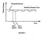
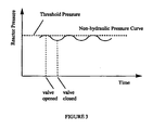
- the valve itself has a diameter of from 4 to 8 cm. (see Figures 2 and 3).
- a hydraulic pressure curve is characteristic of a liquid system wherein the liquid is non-compressible, whereas a non-hydraulic pressure curve is characteristic of a system containing at least some gas.
- the shapes of these curves are distinctive, and measuring a pressure curve for a pressure drop as defined above will allow the determination of whether the system comprises any gaseous products.
- the nature of hydraulic and non-hydraulic systems is well known in the art allowing ready identification of which system is present from the measured pressure curve.
- the shape of the pressure curve allows the distinction between hydraulic and non -hydraulic systems to be determined.
- the shape of the pressure curve is much smoother and there are less pressure variations when product discharge from the reactor occurs, since the gas that is present acts as a damper (see Figures 2 and 3). It will be clear from these Figures that the pressure curve is preferably identified as characteristic of a non-hydraulic system if the curve is not a saw-toothed type curve.
- the selected monomer concentration is higher than in known methods. Typically, the selected monomer concentration ranges from 7-15 wt.%. More preferably, the selected monomer concentration ranges from 10-12 wt.%, and most preferably from 11-12 wt.%.
- the concentration is maintained as high as possible using the present method.
- Monomer concentration may be selected initially at a desired level, and maintained at that level over the course of the reaction.
- the pressure curve is continuously monitored. However, in some embodiments the pressure curve may be measured after a certain time, and/or if the pressure reaches a certain threshold.
- the monomer concentration may be reduced, maintained or increased as desired, based upon the results of the pressure curve monitoring or measurement. If desired, a feedback mechanism may be employed to automate the control of the monomer concentration.
- the temperature employed in the reactor is not particularly limited, and may be selected depending upon the reactants employed, the reactor vessel and the monomer concentration, amongst other factors. Preferably, however, the temperature employed for polymerisation ranges from 70-120°C. More preferably the temperature employed ranges from 80-110°C.
- the solvent employed in the process is not especially limited, provided that it is suitable for polymerising the chosen monomer under the selected reaction conditions.
- the solvent comprises butane and/or hexane, especially for the polymerisation of ethylene or propylene.
- the temperature has an influence on the solubility of the reactants and in general solubility will be higher at lower temperatures. Thus the choice of temperature and solvent is typically taken in combination.
- the olefin monomer is selected from ethylene and propylene.
- the present invention is carried out in an apparatus for polymerising an olefin monomer, which apparatus comprises the following:
- the pressure measurement may be automated and may feed back to the means for controlling the monomer concentration
- the pressure curve is measured.
- the results of this measurement may be fed into an electronic system for controlling monomer concentration, which may prevent or slow the introduction of monomer into the reactor, or may increase the introduction, as desired.
- the means for measuring the presence of gas in the reactor comprises a pressure meter and a valve for releasing pressure in the reactor.
Landscapes
- Chemical & Material Sciences (AREA)
- Chemical Kinetics & Catalysis (AREA)
- Organic Chemistry (AREA)
- Health & Medical Sciences (AREA)
- Medicinal Chemistry (AREA)
- Polymers & Plastics (AREA)
- Polymerisation Methods In General (AREA)
- Addition Polymer Or Copolymer, Post-Treatments, Or Chemical Modifications (AREA)
Abstract
Description
- The present invention concerns an improved method for polymerising olefins in order to prepare polyolefins, in particular for polymerising ethylene. The method is advantageous, since it allows control of the polymerisation reaction at higher olefin monomer concentration than in known processes, which in turn allows greater polyolefin production per unit volume of reactor.
- For many years it has been desirable to increase the efficiency of polyolefin production. One goal has been to increase the quantity of polyolefin that can be produced in a given volume of reactor. The higher the quantity that can be produced, the lower the cost of product production, which provides clear market advantages.
- One method for increasing the quantity of product produced per unit volume of reactor is to increase the concentration of the monomer in the reactor. Clearly, the greater the concentration of the monomer, the greater the concentration of the final product in the reactor. However, there are a number of problems associated with increasing the monomer concentration, as discussed below.
- Generally, polymerisation of olefin monomers is an exothermic reaction. The reaction follows first order kinetics. Thus, the higher the monomer concentration, the faster the reaction proceeds, and the greater the quantity of heat that is released by the reaction process. This heat production may be extremely dangerous if it is not controlled. Clearly a build-up of heat in a reactor containing flammable hydrocarbons may lead to fires or explosions.
- In order to solve this problem and to use as high a monomer concentration as possible, typically two measures have been taken in the past. Firstly, olefin polymerisation reactors have been carefully designed to control the surface area:volume ratio of the reactor. This ensures that there is sufficient surface area to the reaction vessel to allow heat exchange with the outer environment, thus reducing the temperature inside the reactor. Single or double loop reactors are common. These reactors consist of a long pipe, arranged in one or two loops, each loop being tens of meters high. The diameter of the pipes is typically around 60 cm. Such an arrangement has a large surface area:volume ratio as compared with a conventional flask or tank arrangement. Secondly, the reactors are usually jacketed with a cooling system, such as with a water jacket. This serves to efficiently carry away heat from the surface of the reactor, to increase the efficiency of cooling.
- EP-A-0 039 451 discloses a method for controlling the polymerisation process of an olefin monomer comprising monitoring the filiing degree in a polymerisation reactor by measuring pressure change in the reactor upon release of a specific volume of liquid phase olefine monomers in the reactor. The filling degree is used for controlling the residence time of the reactants in the reactor.
- However, generally these methods have only been suitable for monomer concentrations of from 4-6.5 wt.%. This is because a further problem exists with increasing monomer concentration. Often the monomer is gaseous at the temperatures and pressures employed in the reaction. At elevated concentrations of the monomer, the monomer may pass out of solution and form pockets of gas in the reactor. This has clear disadvantages. The gas formed can lead to dangerous pressure build-up. In addition, the release of monomer from the solvent reduces the monomer available for reaction, unbalancing the carefully selected concentration of reactants and leading to undesirable products and impurities. This may have the effect of reducing the efficiency of the process rather than increasing it. Finally, the reactants are typically pumped around the reactor loop for efficient mixing and cooling, but the pumps are designed to pump liquids and will not function properly if gas is present
- It is an aim of the present invention to solve the problems associated with known methods, as discussed above. Thus, the present invention seeks to provide an improved method for polymerising olefins, and in particular for producing polyethylene or polypropylene.
- Accordingly, the present invention provides a method for polymerising an olefin, which method comprises the following steps:
- (a) polymerising an olefin monomer in a reactor, at a selected olefin monomer concentration in a solvent;
- (b) measuring a pressure curve in the reactor to determine whether the pressure curve is characteristic of a hydraulic system or a non-hydraulic system; and
- (c) if the pressure curve is characteristic of a non-hydraulic system, reducing the olefin monomer concentration in the reactor.
- In the context of the present invention, pressure curve means a pressure curve that is deliberately created by initiating a pressure drop. That may be effected by any means, but typically by exposing at least a small part of the reactor to the surroundings for a selected period of time. It is particularly preferred that the pressure drop is initiated by removing product from the reactor. Measurement thus involves recording the change in pressure in the reactor over a specific period of time. These measurements result in a pressure curve, showing the change in pressure over time. If a gas is present, this pressure curve will have a non-hydraulic characteristic. However, if no gas is present, this will be a hydraulic characteristic.
- The method of the present invention is particularly advantageous, since it allows larger quantities of polymer to be produced in the same reactor, without the need to limit the olefin concentration in the reactor in the restricted way in prior art methods. Typically up to double the olefin concentration can be achieved in the present methods, as compared with prior art methods. Polyolefins can be produced more efficiently by this method, at lower cost, leading to a significant market advantage.
- To put the present method in context, a typical process for producing the polymer powder will first be described. Such a process generally employs a turbulent flow reactor such as a continuous pipe reactor in the form of a loop. However, other types of reactors such as stirred reactors may be used.
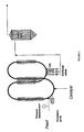
- Polymerisation is carried out in a loop reactor in a circulating turbulent flow. A so-called loop reactor is well known and is described in the Encyclopaedia of Chemical Technology, 3rd edition, vol.16 page 390. This can produce LLDPE (linear low density polyethylene) and HDPE (high density polyethylene) resins in the same type of equipment A loop reactor may be connected in parallel or in series to one or more further reactors, such as another loop reactor. A loop reactor that is connected in series or in parallel to another loop reactor may be referred to as a "double loop" reactor.
- In a double loop reactor the process is a continuous process. A monomer (e.g. ethylene polymerises in a liquid diluent (e.g. isobutene) in the presence of a comonomer (e.g. hexene), hydrogen, catalyst, and activating agent. The slurry is maintained in circulation by an axial pump consisting in a reactor essentially of vertical jacketed pipe sections connected by trough elbows. The polymerisation heat is extracted by a water cooling jacket. The reactor line includes two double loop reactors that can be used in parallel or in series. The approximate volume of the reactors may be about 100m3. Monomodal grades are produced with the parallel or series configuration and bimodal grades are produced with the series configuration.
- The product (e.g. polyethylene) is taken out of the reactor with some diluent through settling legs and discontinuous discharge valves. A small traction of the total circulating flow is withdrawn. It is moved to a polymer degassing section in which the solid content is increased.
- While being depressurised, the slurry is transferred through heated flash lines to a flash tank. In the flash tank, the product and diluent are separated. The degassing is completed in a purge column. A conveyor drying unit may be employed before the purge column in some instances
- The powder product is transported under nitrogen to fluff silos and extruded into pellets along with some specific additives. A pellet treatment unit comprising silos and hot and cool air flows allows the removal of residual components from the pellets. The pellets then are directed to homogenisation silos before final storage.
- This embodiment of the double loop reactor process is usable with chromium type, Ziegler-Natta-type and metallocene-type catalysts. Each catalyst type would have a specific injection system.
- It will be seen from the above that the present invention relates to control of the polymerisation reaction in the production process.
- The present invention will now be described in more detail by way of example only with reference to the following Figures, in which:
- Figure 1 shows a diagram of a double loop reactor with a pressure monitoring means attached;
- Figure 2 shows an example of a hydraulic pressure curve; and
- Figure 3 shows an example of a non-hydraulic pressure curve.
- The pressure curve can be measured using a pressure meter of any standard type. The pressure meter may be connected to the reactor by any means, such as via a connection pipe comprising a valve. Preferably it is installed in the ethylene feed line at the entrance of the reactor. Alternatively, a Dynisco® type transmitter can be placed in the reactor itself in order to better represent the pressure status inside the reactor. The valve may be opened or closed to initiate and end the pressure drop process which gives rise to the pressure curve. Preferably the valve is electronically controlled. Typically, the pressure is continuously measured; this allows the time between discharges through the discharge valves to be controlled in addition to providing the data necessary to identify the pressure drop after a discharge as hydraulic or non-hydraulic.
- In a preferred embodiment, the pressure drop is only initiated when the pressure in the reactor reaches a certain threshold pressure. This threshold pressure may be selected depending on the nature of the reactants, the temperature in the reactor, the monomer concentration, and other characteristics of the reaction system (e.g. choice of catalyst, choice of solvent). These factors all have an influence on the solubility of the reactants, which affects the desired pressure, and are well known in the art. The type of reactor employed may also influence this choice if desired. For instance, a reactor that is taller needs more pressure at the bottom, because the pressure at the top will be lower. Typically a threshold pressure of 35-50 Bar is employed, more preferably from 38-45 Bar and most preferably from 40-43 Bar. A pressure of approximately 43 Bar is particularly preferred. 40 -43 bar, is desirable in a preferred process, using isobutane as a solvent, but other pressures may be appropriate depending on reactants and solvent. Either in addition to this, or as an alternative, pressure drop measurements may be made at a desired time, or point in the process, or simply over regular time periods. The nature of the process and apparatus will determine the frequency and timing of pressure drop measurements.
- Generally the pressure drop is initiated by opening a valve to remove product from the reactor. Since product must be removed from the reactor at periodic intervals (after it collects in the settling legs), and since there is inevitably a pressure drop at this time, then it is often most convenient to initiate the pressure drop by removing product, rather than introducing a separate pressure drop initiation. In a typical embodiment according to the present invention, the valve opens intermittently with a frequency of from 4 to 7 seconds and for a length of time of less than 5 seconds, allowing for a pressure drop of from 0.5 to 1.5 bars, preferably, of about 1 bar. The valve itself has a diameter of from 4 to 8 cm. (see Figures 2 and 3).
- In the present invention, it is important to distinguish between a hydraulic pressure curve and a non hydraulic pressure curve. A hydraulic pressure curve is characteristic of a liquid system wherein the liquid is non-compressible, whereas a non-hydraulic pressure curve is characteristic of a system containing at least some gas. The shapes of these curves are distinctive, and measuring a pressure curve for a pressure drop as defined above will allow the determination of whether the system comprises any gaseous products. The nature of hydraulic and non-hydraulic systems is well known in the art allowing ready identification of which system is present from the measured pressure curve. The shape of the pressure curve allows the distinction between hydraulic and non -hydraulic systems to be determined. Thus, in a non-hydraulic system the shape of the pressure curve is much smoother and there are less pressure variations when product discharge from the reactor occurs, since the gas that is present acts as a damper (see Figures 2 and 3). It will be clear from these Figures that the pressure curve is preferably identified as characteristic of a non-hydraulic system if the curve is not a saw-toothed type curve.
- In the present invention the selected monomer concentration is higher than in known methods. Typically, the selected monomer concentration ranges from 7-15 wt.%. More preferably, the selected monomer concentration ranges from 10-12 wt.%, and most preferably from 11-12 wt.%. The concentration is maintained as high as possible using the present method. Monomer concentration may be selected initially at a desired level, and maintained at that level over the course of the reaction. Preferably, the pressure curve is continuously monitored. However, in some embodiments the pressure curve may be measured after a certain time, and/or if the pressure reaches a certain threshold. The monomer concentration may be reduced, maintained or increased as desired, based upon the results of the pressure curve monitoring or measurement. If desired, a feedback mechanism may be employed to automate the control of the monomer concentration.
- The temperature employed in the reactor is not particularly limited, and may be selected depending upon the reactants employed, the reactor vessel and the monomer concentration, amongst other factors. Preferably, however, the temperature employed for polymerisation ranges from 70-120°C. More preferably the temperature employed ranges from 80-110°C.
- The solvent employed in the process is not especially limited, provided that it is suitable for polymerising the chosen monomer under the selected reaction conditions. Preferably the solvent comprises butane and/or hexane, especially for the polymerisation of ethylene or propylene. The temperature has an influence on the solubility of the reactants and in general solubility will be higher at lower temperatures. Thus the choice of temperature and solvent is typically taken in combination.
- In a particularly preferred embodiment of the invention, the olefin monomer is selected from ethylene and propylene.
- The present invention is carried out in an apparatus for polymerising an olefin monomer, which apparatus comprises the following:
- (a) a reactor for polymerising the olefin monomer;
- (b) a means for measuring the presence of gas in the reactor; and
- (c) a means for controlling the concentration of olefin monomer in the reactor,
- As mentioned above, the pressure measurement may be automated and may feed back to the means for controlling the monomer concentration Thus, after a certain period of time, or at a threshold pressure in the reactor, the pressure curve is measured. The results of this measurement may be fed into an electronic system for controlling monomer concentration, which may prevent or slow the introduction of monomer into the reactor, or may increase the introduction, as desired.
- Preferably, the means for measuring the presence of gas in the reactor comprises a pressure meter and a valve for releasing pressure in the reactor.
Claims (8)
- A method for polymerising an olefin in a loop reactor, which method comprises the following steps:(a) polymerising an olefin monomer in a reactor, in a solvent, at a selected olefin monomer concentration;(b) measuring a pressure curve in the reactor to determine whether the pressure curve is characteristic of a hydraulic system or a non-hydraulic system; and(c) if the pressure curve is characteristic of a non-hydraulic system, reducing the olefin monomer concentration in the reactor.
- A method according to claim 1, wherein the pressure curve is identified as characteristic of a non-hydraulic system if the curve is not a saw-toothed type curve.
- A method according to claim 1 or claim 2, wherein the selected monomer concentration is from 7-15 wt.%
- A method according to claim 3, wherein the selected monomer concentration is from 10-12 wt%
- A method according to any preceding claim, wherein the temperature employed in the reactor is from 70-120°C.
- A method according to claim 5, wherein the temperature employed in the reactor is from 80-110°C.
- A method according to any preceding claim, wherein the solvent employed in the reactor comprises butane, isobutane, and/or hexane.
- A method according to any preceding claim, wherein the olefin monomer is selected from ethylene and propylene.
Priority Applications (1)
| Application Number | Priority Date | Filing Date | Title |
|---|---|---|---|
| EP05707959A EP1597286B1 (en) | 2004-02-13 | 2005-02-08 | Polyolefin production using high olefin concentration |
Applications Claiming Priority (4)
| Application Number | Priority Date | Filing Date | Title |
|---|---|---|---|
| EP04100575 | 2004-02-13 | ||
| EP04100575A EP1564222A1 (en) | 2004-02-13 | 2004-02-13 | Polyolefin production using high olefin concentration |
| EP05707959A EP1597286B1 (en) | 2004-02-13 | 2005-02-08 | Polyolefin production using high olefin concentration |
| PCT/EP2005/050521 WO2005080440A1 (en) | 2004-02-13 | 2005-02-08 | Polyolefin production using high olefin concentration |
Publications (2)
| Publication Number | Publication Date |
|---|---|
| EP1597286A1 EP1597286A1 (en) | 2005-11-23 |
| EP1597286B1 true EP1597286B1 (en) | 2007-05-16 |
Family
ID=34684747
Family Applications (2)
| Application Number | Title | Priority Date | Filing Date |
|---|---|---|---|
| EP04100575A Withdrawn EP1564222A1 (en) | 2004-02-13 | 2004-02-13 | Polyolefin production using high olefin concentration |
| EP05707959A Expired - Lifetime EP1597286B1 (en) | 2004-02-13 | 2005-02-08 | Polyolefin production using high olefin concentration |
Family Applications Before (1)
| Application Number | Title | Priority Date | Filing Date |
|---|---|---|---|
| EP04100575A Withdrawn EP1564222A1 (en) | 2004-02-13 | 2004-02-13 | Polyolefin production using high olefin concentration |
Country Status (12)
| Country | Link |
|---|---|
| US (2) | US20070060723A1 (en) |
| EP (2) | EP1564222A1 (en) |
| JP (1) | JP5307336B2 (en) |
| KR (1) | KR101149620B1 (en) |
| CN (1) | CN100432110C (en) |
| AT (1) | ATE362492T1 (en) |
| DE (1) | DE602005001133T2 (en) |
| DK (1) | DK1597286T3 (en) |
| EA (1) | EA009423B1 (en) |
| ES (1) | ES2285681T3 (en) |
| PT (1) | PT1597286E (en) |
| WO (1) | WO2005080440A1 (en) |
Families Citing this family (4)
| Publication number | Priority date | Publication date | Assignee | Title |
|---|---|---|---|---|
| EP1564222A1 (en) * | 2004-02-13 | 2005-08-17 | Total Petrochemicals Research Feluy | Polyolefin production using high olefin concentration |
| EP2030993A1 (en) * | 2007-09-03 | 2009-03-04 | INEOS Manufacturing Belgium NV | Slurry phase polymerisation process |
| US8202949B2 (en) * | 2008-08-26 | 2012-06-19 | Chevron Phillips Chemical Company Lp | System and method for measuring pressure and flow in a loop reactor |
| KR102462535B1 (en) * | 2019-10-17 | 2022-11-01 | 주식회사 엘지화학 | Apparatus for preparing |
Family Cites Families (12)
| Publication number | Priority date | Publication date | Assignee | Title |
|---|---|---|---|---|
| US2917465A (en) * | 1956-04-27 | 1959-12-15 | Phillips Petroleum Co | Polymerization catalyst feed control |
| US3257362A (en) | 1960-11-21 | 1966-06-21 | Phillips Petroleum Co | Control of olefin polymerization reactions |
| US3293000A (en) * | 1962-10-05 | 1966-12-20 | Phillips Petroleum Co | Withdrawal of solids from a flowing stream comprising a slurry of same |
| DE3016873A1 (en) * | 1980-05-02 | 1981-11-05 | Bayer Ag, 5090 Leverkusen | METHOD FOR THE CONTINUOUS PRODUCTION OF POLYMER DISPERSIONS UNDER PRESSURE |
| JPS58111808A (en) * | 1981-12-25 | 1983-07-04 | Mitsubishi Chem Ind Ltd | Method and apparatus for production of polyolefin |
| FR2594548B1 (en) * | 1986-02-19 | 1989-05-19 | Bp Chimie Sa | METHOD AND DEVICE FOR DETECTING ABNORMALITIES IN A FLUIDIZED BED AND APPLICATION TO REACTORS WITH A FLUIDIZED BED FOR POLYMERIZING ALPHAOLEFINS IN THE GASEOUS PHASE |
| EP0891381B2 (en) * | 1996-04-01 | 2006-05-24 | The Dow Chemical Company | Olefin solution polymerization |
| BR9803848A (en) * | 1998-10-08 | 2000-10-31 | Opp Petroquimica S A | Inline system for inference of physical and chemical properties, inline system for inference of process variables, and inline control system |
| US6301546B1 (en) * | 1999-01-22 | 2001-10-09 | Exxon Research And Engineering Company | Process for detecting and monitoring changes in properties of fluidized bed solids by pressure difference fluctuation measurement |
| US6916892B2 (en) * | 2001-12-03 | 2005-07-12 | Fina Technology, Inc. | Method for transitioning between Ziegler-Natta and metallocene catalysts in a bulk loop reactor for the production of polypropylene |
| US20050272891A1 (en) * | 2004-02-13 | 2005-12-08 | Atofina Research S.A. | Double loop technology |
| EP1564222A1 (en) * | 2004-02-13 | 2005-08-17 | Total Petrochemicals Research Feluy | Polyolefin production using high olefin concentration |
-
2004
- 2004-02-13 EP EP04100575A patent/EP1564222A1/en not_active Withdrawn
-
2005
- 2005-02-08 AT AT05707959T patent/ATE362492T1/en not_active IP Right Cessation
- 2005-02-08 ES ES05707959T patent/ES2285681T3/en not_active Expired - Lifetime
- 2005-02-08 PT PT05707959T patent/PT1597286E/en unknown
- 2005-02-08 EP EP05707959A patent/EP1597286B1/en not_active Expired - Lifetime
- 2005-02-08 DE DE602005001133T patent/DE602005001133T2/en not_active Expired - Lifetime
- 2005-02-08 WO PCT/EP2005/050521 patent/WO2005080440A1/en not_active Ceased
- 2005-02-08 EA EA200601481A patent/EA009423B1/en not_active IP Right Cessation
- 2005-02-08 KR KR1020067018041A patent/KR101149620B1/en not_active Expired - Fee Related
- 2005-02-08 DK DK05707959T patent/DK1597286T3/en active
- 2005-02-08 JP JP2006552605A patent/JP5307336B2/en not_active Expired - Fee Related
- 2005-02-08 CN CNB200580004374XA patent/CN100432110C/en not_active Expired - Fee Related
-
2006
- 2006-08-01 US US11/499,042 patent/US20070060723A1/en not_active Abandoned
-
2009
- 2009-10-26 US US12/605,614 patent/US7902306B2/en not_active Expired - Fee Related
Non-Patent Citations (1)
| Title |
|---|
| None * |
Also Published As
| Publication number | Publication date |
|---|---|
| US20070060723A1 (en) | 2007-03-15 |
| CN1918183A (en) | 2007-02-21 |
| DE602005001133D1 (en) | 2007-06-28 |
| JP2007522304A (en) | 2007-08-09 |
| ATE362492T1 (en) | 2007-06-15 |
| EA200601481A1 (en) | 2007-02-27 |
| US20100144982A1 (en) | 2010-06-10 |
| EA009423B1 (en) | 2007-12-28 |
| EP1564222A1 (en) | 2005-08-17 |
| US7902306B2 (en) | 2011-03-08 |
| DE602005001133T2 (en) | 2008-01-10 |
| ES2285681T3 (en) | 2007-11-16 |
| KR20070004690A (en) | 2007-01-09 |
| JP5307336B2 (en) | 2013-10-02 |
| KR101149620B1 (en) | 2012-07-04 |
| WO2005080440A1 (en) | 2005-09-01 |
| PT1597286E (en) | 2007-06-14 |
| EP1597286A1 (en) | 2005-11-23 |
| CN100432110C (en) | 2008-11-12 |
| DK1597286T3 (en) | 2007-09-24 |
Similar Documents
| Publication | Publication Date | Title |
|---|---|---|
| US8475720B2 (en) | Method for improving a polymerization reaction by taking out and analysing a sample | |
| US9273162B2 (en) | Process for monitoring the polymerization of ethylene or ethylene and comonomers in a tubular-reactor at high-pressures | |
| CN107223137B (en) | The high pressure polymerization process of ethylenically unsaturated monomer | |
| CN102282180B (en) | Process for the polymerization of ethylene in a reduced output tubular reactor | |
| US7902307B2 (en) | Olefin polymerization process with optimized product discharge | |
| RU2674968C1 (en) | Separator with integrated bursting discs for separation of components of reaction mixture obtained by high-pressure polymerisation of ethylenically unsaturated monomers | |
| US8940239B2 (en) | Catalyst feed control during catalyst transition periods | |
| US9931608B2 (en) | Process for separating components of a polymer-monomer mixture obtained by high-pressure polymerization of ethylenically unsaturated monomers | |
| WO2015082565A1 (en) | Process for separating components of a reaction mixture obtained by high-pressure polymerization of ethylenically unsaturated monomers | |
| US7902306B2 (en) | Polyolefin production using high olefin concentration | |
| EP3898708B1 (en) | High-pressure polymerization process of ethylenically unsaturated monomers in a polymerization reactor | |
| US12540205B2 (en) | Cooling of reaction mixture obtained by high-pressure polymerization process of ethylenically unsaturated monomers | |
| EP3845572A1 (en) | Process for the polymerization of olefins in solution with controlled activity of catalyst in reactor outlet stream | |
| CN118788239B (en) | Method for monitoring the state of discharge material in high-pressure free radical polymerization | |
| RU2793547C1 (en) | Cooling of the reaction mixture produced by the method of polymerization of ethylene-unsaturated monomers under high pressure | |
| BR112022008822B1 (en) | PROCESS FOR PREPARING ETHYLENE POLYMERS |
Legal Events
| Date | Code | Title | Description |
|---|---|---|---|
| PUAI | Public reference made under article 153(3) epc to a published international application that has entered the european phase |
Free format text: ORIGINAL CODE: 0009012 |
|
| 17P | Request for examination filed |
Effective date: 20050512 |
|
| AK | Designated contracting states |
Kind code of ref document: A1 Designated state(s): AT BE BG CH CY CZ DE DK EE ES FI FR GB GR HU IE IS IT LI LT LU MC NL PL PT RO SE SI SK TR |
|
| AX | Request for extension of the european patent |
Extension state: AL BA HR LV MK YU |
|
| GRAP | Despatch of communication of intention to grant a patent |
Free format text: ORIGINAL CODE: EPIDOSNIGR1 |
|
| RBV | Designated contracting states (corrected) |
Designated state(s): AT BE BG CH CY CZ DE DK EE ES FI FR GB GR HU IE IS IT LI LT LU MC NL PL PT RO SE SI SK TR |
|
| GRAS | Grant fee paid |
Free format text: ORIGINAL CODE: EPIDOSNIGR3 |
|
| GRAA | (expected) grant |
Free format text: ORIGINAL CODE: 0009210 |
|
| AK | Designated contracting states |
Kind code of ref document: B1 Designated state(s): AT BE BG CH CY CZ DE DK EE ES FI FR GB GR HU IE IS IT LI LT LU MC NL PL PT RO SE SI SK TR |
|
| PG25 | Lapsed in a contracting state [announced via postgrant information from national office to epo] |
Ref country code: CH Free format text: LAPSE BECAUSE OF FAILURE TO SUBMIT A TRANSLATION OF THE DESCRIPTION OR TO PAY THE FEE WITHIN THE PRESCRIBED TIME-LIMIT Effective date: 20070516 Ref country code: LI Free format text: LAPSE BECAUSE OF FAILURE TO SUBMIT A TRANSLATION OF THE DESCRIPTION OR TO PAY THE FEE WITHIN THE PRESCRIBED TIME-LIMIT Effective date: 20070516 |
|
| REG | Reference to a national code |
Ref country code: GB Ref legal event code: FG4D |
|
| REG | Reference to a national code |
Ref country code: PT Ref legal event code: SC4A Free format text: AVAILABILITY OF NATIONAL TRANSLATION Effective date: 20070531 |
|
| REG | Reference to a national code |
Ref country code: CH Ref legal event code: EP |
|
| REG | Reference to a national code |
Ref country code: IE Ref legal event code: FG4D |
|
| REF | Corresponds to: |
Ref document number: 602005001133 Country of ref document: DE Date of ref document: 20070628 Kind code of ref document: P |
|
| ET | Fr: translation filed | ||
| REG | Reference to a national code |
Ref country code: SE Ref legal event code: TRGR |
|
| PG25 | Lapsed in a contracting state [announced via postgrant information from national office to epo] |
Ref country code: IS Free format text: LAPSE BECAUSE OF FAILURE TO SUBMIT A TRANSLATION OF THE DESCRIPTION OR TO PAY THE FEE WITHIN THE PRESCRIBED TIME-LIMIT Effective date: 20070916 |
|
| REG | Reference to a national code |
Ref country code: ES Ref legal event code: FG2A Ref document number: 2285681 Country of ref document: ES Kind code of ref document: T3 |
|
| PG25 | Lapsed in a contracting state [announced via postgrant information from national office to epo] |
Ref country code: PL Free format text: LAPSE BECAUSE OF FAILURE TO SUBMIT A TRANSLATION OF THE DESCRIPTION OR TO PAY THE FEE WITHIN THE PRESCRIBED TIME-LIMIT Effective date: 20070516 Ref country code: AT Free format text: LAPSE BECAUSE OF FAILURE TO SUBMIT A TRANSLATION OF THE DESCRIPTION OR TO PAY THE FEE WITHIN THE PRESCRIBED TIME-LIMIT Effective date: 20070516 |
|
| REG | Reference to a national code |
Ref country code: CH Ref legal event code: PL |
|
| PG25 | Lapsed in a contracting state [announced via postgrant information from national office to epo] |
Ref country code: BG Free format text: LAPSE BECAUSE OF FAILURE TO SUBMIT A TRANSLATION OF THE DESCRIPTION OR TO PAY THE FEE WITHIN THE PRESCRIBED TIME-LIMIT Effective date: 20070816 Ref country code: SI Free format text: LAPSE BECAUSE OF FAILURE TO SUBMIT A TRANSLATION OF THE DESCRIPTION OR TO PAY THE FEE WITHIN THE PRESCRIBED TIME-LIMIT Effective date: 20070516 Ref country code: CZ Free format text: LAPSE BECAUSE OF FAILURE TO SUBMIT A TRANSLATION OF THE DESCRIPTION OR TO PAY THE FEE WITHIN THE PRESCRIBED TIME-LIMIT Effective date: 20070516 |
|
| PG25 | Lapsed in a contracting state [announced via postgrant information from national office to epo] |
Ref country code: LT Free format text: LAPSE BECAUSE OF FAILURE TO SUBMIT A TRANSLATION OF THE DESCRIPTION OR TO PAY THE FEE WITHIN THE PRESCRIBED TIME-LIMIT Effective date: 20070516 Ref country code: SK Free format text: LAPSE BECAUSE OF FAILURE TO SUBMIT A TRANSLATION OF THE DESCRIPTION OR TO PAY THE FEE WITHIN THE PRESCRIBED TIME-LIMIT Effective date: 20070516 |
|
| PLBE | No opposition filed within time limit |
Free format text: ORIGINAL CODE: 0009261 |
|
| STAA | Information on the status of an ep patent application or granted ep patent |
Free format text: STATUS: NO OPPOSITION FILED WITHIN TIME LIMIT |
|
| 26N | No opposition filed |
Effective date: 20080219 |
|
| PG25 | Lapsed in a contracting state [announced via postgrant information from national office to epo] |
Ref country code: GR Free format text: LAPSE BECAUSE OF FAILURE TO SUBMIT A TRANSLATION OF THE DESCRIPTION OR TO PAY THE FEE WITHIN THE PRESCRIBED TIME-LIMIT Effective date: 20070817 |
|
| PG25 | Lapsed in a contracting state [announced via postgrant information from national office to epo] |
Ref country code: RO Free format text: LAPSE BECAUSE OF FAILURE TO SUBMIT A TRANSLATION OF THE DESCRIPTION OR TO PAY THE FEE WITHIN THE PRESCRIBED TIME-LIMIT Effective date: 20070516 |
|
| PG25 | Lapsed in a contracting state [announced via postgrant information from national office to epo] |
Ref country code: MC Free format text: LAPSE BECAUSE OF NON-PAYMENT OF DUE FEES Effective date: 20080228 |
|
| PG25 | Lapsed in a contracting state [announced via postgrant information from national office to epo] |
Ref country code: IE Free format text: LAPSE BECAUSE OF NON-PAYMENT OF DUE FEES Effective date: 20080208 Ref country code: EE Free format text: LAPSE BECAUSE OF FAILURE TO SUBMIT A TRANSLATION OF THE DESCRIPTION OR TO PAY THE FEE WITHIN THE PRESCRIBED TIME-LIMIT Effective date: 20070516 |
|
| PG25 | Lapsed in a contracting state [announced via postgrant information from national office to epo] |
Ref country code: CY Free format text: LAPSE BECAUSE OF FAILURE TO SUBMIT A TRANSLATION OF THE DESCRIPTION OR TO PAY THE FEE WITHIN THE PRESCRIBED TIME-LIMIT Effective date: 20070516 |
|
| PG25 | Lapsed in a contracting state [announced via postgrant information from national office to epo] |
Ref country code: LU Free format text: LAPSE BECAUSE OF NON-PAYMENT OF DUE FEES Effective date: 20080208 Ref country code: HU Free format text: LAPSE BECAUSE OF FAILURE TO SUBMIT A TRANSLATION OF THE DESCRIPTION OR TO PAY THE FEE WITHIN THE PRESCRIBED TIME-LIMIT Effective date: 20071117 |
|
| PGFP | Annual fee paid to national office [announced via postgrant information from national office to epo] |
Ref country code: TR Payment date: 20120208 Year of fee payment: 8 |
|
| PGFP | Annual fee paid to national office [announced via postgrant information from national office to epo] |
Ref country code: IT Payment date: 20120221 Year of fee payment: 8 |
|
| PGFP | Annual fee paid to national office [announced via postgrant information from national office to epo] |
Ref country code: FI Payment date: 20130213 Year of fee payment: 9 Ref country code: SE Payment date: 20130219 Year of fee payment: 9 Ref country code: FR Payment date: 20130301 Year of fee payment: 9 Ref country code: DK Payment date: 20130218 Year of fee payment: 9 Ref country code: GB Payment date: 20130218 Year of fee payment: 9 Ref country code: DE Payment date: 20130219 Year of fee payment: 9 Ref country code: ES Payment date: 20130227 Year of fee payment: 9 |
|
| PGFP | Annual fee paid to national office [announced via postgrant information from national office to epo] |
Ref country code: NL Payment date: 20130219 Year of fee payment: 9 Ref country code: BE Payment date: 20130220 Year of fee payment: 9 |
|
| PGFP | Annual fee paid to national office [announced via postgrant information from national office to epo] |
Ref country code: PT Payment date: 20130204 Year of fee payment: 9 |
|
| REG | Reference to a national code |
Ref country code: PT Ref legal event code: MM4A Free format text: LAPSE DUE TO NON-PAYMENT OF FEES Effective date: 20140808 |
|
| BERE | Be: lapsed |
Owner name: TOTAL PETROCHEMICALS RESEARCH FELUY Effective date: 20140228 |
|
| REG | Reference to a national code |
Ref country code: DE Ref legal event code: R119 Ref document number: 602005001133 Country of ref document: DE |
|
| REG | Reference to a national code |
Ref country code: NL Ref legal event code: V1 Effective date: 20140901 |
|
| REG | Reference to a national code |
Ref country code: DK Ref legal event code: EBP Effective date: 20140228 |
|
| REG | Reference to a national code |
Ref country code: SE Ref legal event code: EUG |
|
| GBPC | Gb: european patent ceased through non-payment of renewal fee |
Effective date: 20140208 |
|
| PG25 | Lapsed in a contracting state [announced via postgrant information from national office to epo] |
Ref country code: FI Free format text: LAPSE BECAUSE OF NON-PAYMENT OF DUE FEES Effective date: 20140208 Ref country code: NL Free format text: LAPSE BECAUSE OF NON-PAYMENT OF DUE FEES Effective date: 20140901 |
|
| REG | Reference to a national code |
Ref country code: FR Ref legal event code: ST Effective date: 20141031 |
|
| REG | Reference to a national code |
Ref country code: DE Ref legal event code: R119 Ref document number: 602005001133 Country of ref document: DE Effective date: 20140902 |
|
| PG25 | Lapsed in a contracting state [announced via postgrant information from national office to epo] |
Ref country code: SE Free format text: LAPSE BECAUSE OF NON-PAYMENT OF DUE FEES Effective date: 20140209 |
|
| PG25 | Lapsed in a contracting state [announced via postgrant information from national office to epo] |
Ref country code: PT Free format text: LAPSE BECAUSE OF NON-PAYMENT OF DUE FEES Effective date: 20140808 |
|
| PG25 | Lapsed in a contracting state [announced via postgrant information from national office to epo] |
Ref country code: DE Free format text: LAPSE BECAUSE OF NON-PAYMENT OF DUE FEES Effective date: 20140902 Ref country code: GB Free format text: LAPSE BECAUSE OF NON-PAYMENT OF DUE FEES Effective date: 20140208 Ref country code: DK Free format text: LAPSE BECAUSE OF NON-PAYMENT OF DUE FEES Effective date: 20140228 Ref country code: BE Free format text: LAPSE BECAUSE OF NON-PAYMENT OF DUE FEES Effective date: 20140228 Ref country code: FR Free format text: LAPSE BECAUSE OF NON-PAYMENT OF DUE FEES Effective date: 20140228 |
|
| REG | Reference to a national code |
Ref country code: ES Ref legal event code: FD2A Effective date: 20150429 |
|
| PG25 | Lapsed in a contracting state [announced via postgrant information from national office to epo] |
Ref country code: ES Free format text: LAPSE BECAUSE OF NON-PAYMENT OF DUE FEES Effective date: 20140209 |
|
| PG25 | Lapsed in a contracting state [announced via postgrant information from national office to epo] |
Ref country code: IT Free format text: LAPSE BECAUSE OF NON-PAYMENT OF DUE FEES Effective date: 20140208 |
|
| PG25 | Lapsed in a contracting state [announced via postgrant information from national office to epo] |
Ref country code: TR Free format text: LAPSE BECAUSE OF NON-PAYMENT OF DUE FEES Effective date: 20140208 |