EP1597134B1 - Semi-trailer chassis and wheel suspension - Google Patents
Semi-trailer chassis and wheel suspension Download PDFInfo
- Publication number
- EP1597134B1 EP1597134B1 EP04714245A EP04714245A EP1597134B1 EP 1597134 B1 EP1597134 B1 EP 1597134B1 EP 04714245 A EP04714245 A EP 04714245A EP 04714245 A EP04714245 A EP 04714245A EP 1597134 B1 EP1597134 B1 EP 1597134B1
- Authority
- EP
- European Patent Office
- Prior art keywords
- semi
- chassis
- trailer
- mentioned
- trailer according
- Prior art date
- Legal status (The legal status is an assumption and is not a legal conclusion. Google has not performed a legal analysis and makes no representation as to the accuracy of the status listed.)
- Expired - Lifetime
Links
- 239000000725 suspension Substances 0.000 title description 5
- 238000010276 construction Methods 0.000 claims description 14
- 230000008878 coupling Effects 0.000 claims description 5
- 238000010168 coupling process Methods 0.000 claims description 5
- 238000005859 coupling reaction Methods 0.000 claims description 5
- 230000002787 reinforcement Effects 0.000 claims description 4
- 230000005484 gravity Effects 0.000 description 4
- 238000005452 bending Methods 0.000 description 2
- 230000001955 cumulated effect Effects 0.000 description 1
- 239000007788 liquid Substances 0.000 description 1
- 239000002184 metal Substances 0.000 description 1
- 230000000630 rising effect Effects 0.000 description 1
Images


Classifications
-
- B—PERFORMING OPERATIONS; TRANSPORTING
- B60—VEHICLES IN GENERAL
- B60G—VEHICLE SUSPENSION ARRANGEMENTS
- B60G3/00—Resilient suspensions for a single wheel
- B60G3/18—Resilient suspensions for a single wheel with two or more pivoted arms, e.g. parallelogram
- B60G3/20—Resilient suspensions for a single wheel with two or more pivoted arms, e.g. parallelogram all arms being rigid
-
- B—PERFORMING OPERATIONS; TRANSPORTING
- B60—VEHICLES IN GENERAL
- B60G—VEHICLE SUSPENSION ARRANGEMENTS
- B60G3/00—Resilient suspensions for a single wheel
- B60G3/18—Resilient suspensions for a single wheel with two or more pivoted arms, e.g. parallelogram
-
- B—PERFORMING OPERATIONS; TRANSPORTING
- B60—VEHICLES IN GENERAL
- B60G—VEHICLE SUSPENSION ARRANGEMENTS
- B60G7/00—Pivoted suspension arms; Accessories thereof
- B60G7/02—Attaching arms to sprung part of vehicle
-
- B—PERFORMING OPERATIONS; TRANSPORTING
- B62—LAND VEHICLES FOR TRAVELLING OTHERWISE THAN ON RAILS
- B62D—MOTOR VEHICLES; TRAILERS
- B62D53/00—Tractor-trailer combinations; Road trains
- B62D53/04—Tractor-trailer combinations; Road trains comprising a vehicle carrying an essential part of the other vehicle's load by having supporting means for the front or rear part of the other vehicle
- B62D53/06—Semi-trailers
- B62D53/061—Semi-trailers of flat bed or low loader type or fitted with swan necks
-
- B—PERFORMING OPERATIONS; TRANSPORTING
- B60—VEHICLES IN GENERAL
- B60G—VEHICLE SUSPENSION ARRANGEMENTS
- B60G2200/00—Indexing codes relating to suspension types
- B60G2200/10—Independent suspensions
- B60G2200/14—Independent suspensions with lateral arms
- B60G2200/144—Independent suspensions with lateral arms with two lateral arms forming a parallelogram
-
- B—PERFORMING OPERATIONS; TRANSPORTING
- B60—VEHICLES IN GENERAL
- B60G—VEHICLE SUSPENSION ARRANGEMENTS
- B60G2200/00—Indexing codes relating to suspension types
- B60G2200/10—Independent suspensions
- B60G2200/18—Multilink suspensions, e.g. elastokinematic arrangements
-
- B—PERFORMING OPERATIONS; TRANSPORTING
- B60—VEHICLES IN GENERAL
- B60G—VEHICLE SUSPENSION ARRANGEMENTS
- B60G2202/00—Indexing codes relating to the type of spring, damper or actuator
- B60G2202/10—Type of spring
- B60G2202/15—Fluid spring
- B60G2202/152—Pneumatic spring
-
- B—PERFORMING OPERATIONS; TRANSPORTING
- B60—VEHICLES IN GENERAL
- B60G—VEHICLE SUSPENSION ARRANGEMENTS
- B60G2204/00—Indexing codes related to suspensions per se or to auxiliary parts
- B60G2204/10—Mounting of suspension elements
- B60G2204/12—Mounting of springs or dampers
- B60G2204/126—Mounting of pneumatic springs
-
- B—PERFORMING OPERATIONS; TRANSPORTING
- B60—VEHICLES IN GENERAL
- B60G—VEHICLE SUSPENSION ARRANGEMENTS
- B60G2204/00—Indexing codes related to suspensions per se or to auxiliary parts
- B60G2204/10—Mounting of suspension elements
- B60G2204/14—Mounting of suspension arms
- B60G2204/143—Mounting of suspension arms on the vehicle body or chassis
-
- B—PERFORMING OPERATIONS; TRANSPORTING
- B60—VEHICLES IN GENERAL
- B60G—VEHICLE SUSPENSION ARRANGEMENTS
- B60G2204/00—Indexing codes related to suspensions per se or to auxiliary parts
- B60G2204/40—Auxiliary suspension parts; Adjustment of suspensions
- B60G2204/416—Ball or spherical joints
-
- B—PERFORMING OPERATIONS; TRANSPORTING
- B60—VEHICLES IN GENERAL
- B60G—VEHICLE SUSPENSION ARRANGEMENTS
- B60G2204/00—Indexing codes related to suspensions per se or to auxiliary parts
- B60G2204/40—Auxiliary suspension parts; Adjustment of suspensions
- B60G2204/44—Centering or positioning means
- B60G2204/4404—Retainers for holding a fixing element, e.g. bushing, nut, bolt etc., until it is tightly fixed in position
-
- B—PERFORMING OPERATIONS; TRANSPORTING
- B60—VEHICLES IN GENERAL
- B60G—VEHICLE SUSPENSION ARRANGEMENTS
- B60G2206/00—Indexing codes related to the manufacturing of suspensions: constructional features, the materials used, procedures or tools
- B60G2206/01—Constructional features of suspension elements, e.g. arms, dampers, springs
- B60G2206/60—Subframe construction
-
- B—PERFORMING OPERATIONS; TRANSPORTING
- B60—VEHICLES IN GENERAL
- B60G—VEHICLE SUSPENSION ARRANGEMENTS
- B60G2300/00—Indexing codes relating to the type of vehicle
- B60G2300/04—Trailers
- B60G2300/042—Semi-trailers
Definitions
- the present invention concerns an improved semi-trailer.
- a conventional semi-trailer mainly consists of a chassis, consisting of two parallel, supporting, longitudinal runners which are connected to each other by means of cross beams, and of one or several rigid wheel axles with single or double wheels upon which the chassis is provided by means of springs provided between the longitudinal runners and the wheel axles.
- such a semi-trailer is equipped with a loading floor, provided between two edge profiles on the side edges of the chassis, whereby these edge profiles can be used to apply a superstructure in the shape of a tilt construction, sidewalls or the like, or which can be used to lash down loads or the like.
- a disadvantage of the known semi-trailers, as i.e. disclosed in DE 100 35 273 (which also discloses the preamble to claim 1) is that they have a relatively large empty weight, among others due to the relatively large own weight of the longitudinal runners, edge profiles and wheel axles.
- Another disadvantage is that the entire loading floor is always situated above the wheel level, so that the centre of gravity of the load is always situated relatively far from the ground, which is disadvantageous to the stability.
- the present invention aims to remedy the above-mentioned and other disadvantages by providing an improved semi-trailer which is considerably lighter than the known semi-trailers and which moreover is much more stable during transport, so that the risk of tilting in bends or on bad roads is drastically reduced.
- the invention concerns an improved semi-trailer which mainly consists of a chassis with at least two supporting longitudinal runners, connected to each other by means of cross connections, and two or several single or double wheels carrying the chassis, whereby the longitudinal runners are situated on the side edges of the chassis at a distance from each other which is larger than the distance between the wheels, and whereby every wheel is fixed independently of the other wheels on the chassis by means of two parallel supporting arms which are provided in pairs on the chassis (14), on top of each other and at a distance from each other, and which supporting arms (32-33) are hinge-mounted on a central longitudinal directed support (24) which is part of the chassis (14).
- An advantage of an improved semi-trailer according to the invention is that, since the longitudinal runners are situated on the side edges of the chassis, these longitudinal runners can also serve as edge profiles, such that the edge profiles can be omitted in this case, which allows for a considerable weight saving in the order of magnitude of 350 kg.
- Another advantage is that, by replacing the rigid wheel axles by independently spring-mounted wheel suspensions with hinged supporting arms, an additional weight saving of some 80 to 100 kg per axle becomes possible, such that, for example for a semi-trailer with three axles, some 300 kg can be easily saved.
- An additional advantage, related to the use of independently spring-mounted wheels, is that the semi-trailer's stability is improved as the wheels keep better contact with the road, which is particularly important on bad grounds.
- Each of the above-mentioned supporting longitudinal runners is preferably formed of a profile provided with a reinforcement in the shape of a box-like construction in a central part of the longitudinal runner over a certain length, in particular in the part of the longitudinal runner situated between the wheels and the journal of the semi-trailer and which, as is known, is loaded the most.
- a profile can be used for the construction of the longitudinal runners which is considerably lighter than the usual I-profiles which have been used until now to form the longitudinal runners in the known semi-trailers, such that this allows for a considerable additional weight saving.
- one or several of the above-mentioned cross connections have a concave form, such that the chassis, in the places where these cross beams are situated, will so to say have a recessed part in relation to the level of the longitudinal runners, such that the load can be placed lower in this recessed part than with the known semi-trailers, and the centre of gravity of the load will be situated lower as a result, which is reflected in an improved stability.
- Figures 1 and 2 represent a semi-trailer 1 of a known type by way of example, with a chassis 2 which in this case is suspended at the back on three rigid axles 3 with some wheels 4 and which is provided with ground props 5 in front with which the semi-trailer 1, as represented in figure 1, as separate from a lorry, can be erected in a parking place or the like, and which is equipped with a coupling element 7 on the journal 6 of the semi-trailer 1 with which the semi-trailer 1 can be coupled to a lorry in a hingeable manner.
- the chassis 2 of this known semi-trailer is formed of two parallel longitudinal runners 8 in the shape of two heavy I-profiles which are provided on the rigid axles 3 by means of springs 9 and which are connected to each other by means of cross profiles 10 extending on either side of the chassis 2 and onto which are fixed two edge profiles 11 on the side edges of the chassis 2 in between which is provided a loading floor 12.
- the above-mentioned I-profiles in this case have a constant section, save in the front part forming the journal 6 of the chassis, where the I-profile is less high.
- Figures 3 to 6 represent an improved semi-trailer 13 according to the invention with comparable dimensions and the same number of wheel axles as the above-described known conventional semi-trailer 1, but in this case with independently suspended wheels 4.
- the chassis 14 of this semi-trailer 13 is in this case also formed of two parallel longitudinal runners 15 which are connected to each other by means of cross connections 16-17-18, whereby these longitudinal runners 15 are not provided between the wheels 4 according to the invention, but on the side edges of the chassis 14, at a distance which is larger than the lateral clearance between the wheels, and whereby these longitudinal runners 15 also form edge profiles onto which can be fixed a non-represented loading floor and/or a superstructure, and upon which can also be provided points of attachment for lashing down loads or the like.
- Every longitudinal runner 15 is formed of a profile 19 according to the invention, for example a C-profile or a welded I-profile as represented, and of a reinforcement in the shape of a flat box-like construction 20 extending over a certain length in a central part of the longitudinal runner 15, which part is mainly situated between the wheels 4 and the journal 21, where the bending moments caused by the loads are the largest.
- the box-like construction 20 extends downward as of the I-profile 19 and is formed of the I-profile 19 itself and a profile 22 running parallel to it which is connected to the I-profile 19 by means of profiles 23.
- every longitudinal runner 15 can be made much lighter than a corresponding longitudinal runner 8 of the above-described known semi-trailer 1, such that the chassis 14 as a whole, partly thanks to the fact that no extra edge profiles 11 are required in this case, can be made considerably lighter than the chassis 2 of a comparable known semi-trailer 1.
- a central support 24 which in this case is formed of two central longitudinal profiles 25 and 26 situated on top of each other, which are each attached to the two longitudinal runners 15 by means of two slantingly rising profiles, 27-28 and 29-30 respectively, of the cross connections 18.
- the cross connections 18 on either side of each wheel 4 are formed of V-shaped box-like constructions which mainly consist of the above-mentioned profiles 27-28-29-30 which are connected to each other by means of profiles 31.
- Every wheel 4 is independently suspended onto the chassis 14 by means of two parallel supporting arms, 32 and 33 respectively, which are hinge-mounted between the above-mentioned longitudinal profiles 25-26 and a supporting plate 34 for the wheel 4 concerned, in particular a supporting plate 34 in which the wheel stub is provided.
- Every supporting arm 32-33 is mainly formed of two hinge joints 35 which, as is represented in figures 7 and 8, are fixed on supports 38 on one of either longitudinal profiles 25-26 with their hinge pin 37, as well as by means of a third hinge joint 39 which is connected to the above-said hinge joints 35 by means of two rods 40 in a triangular bracing and whose hinge pin 41, as represented in figures 9 and 10, is fixed to the above-mentioned supporting plate 34 by means of bolts 42, which is provided with a forked part with two legs 43 at the top and at the bottom to this end, in between which the hinge joint 39 concerned of a lower supporting arm 32 or of a top supporting arm 33 is provided.
- hinge joints 35 have coaxial axes, it is not excluded for the hinge joints 35 to be mounted at an angle in relation to each other.
- a suspension 44 for example in the shape of a known pneumatic or hydraulic suspension.
- the vertical distance between the hinge joints on one and the same supporting plate 34 is preferably equal to the vertical distance between the hinge joints 35 on the supports formed of the lower and the top longitudinal profile 25-26, such that the supporting arms 25-26 always remain parallel to each other, and the wheel 4 attached to it stays mainly parallel to itself.
- Figure 11 represents a variant of a semi-trailer 13 according to the invention which in this case is embodied with a bucket 45 whose bottom 46 is made trough-shaped, and whereby this bottom 46 is mainly provided between the longitudinal runners 15.
- the cross connections 17-18 must have a concave form over a certain length of the semi-trailer 13, so that a bed is formed so to say in which the bucket 45 fits.
- Figure 12 represents another variant of a semi-trailer 13 according to the invention, in particular a semi-trailer 13 for a tank 50 for the transport of liquids or bulk goods.
- the cross connections 17-18 are formed of two profiles 47 with which a longitudinal profile 48 is fixed to the longitudinal runners 15, and whereby a cross connection 49 is provided between the profiles 47.
- the longitudinal profile 48 and the cross connection 49 in this case form the above-mentioned central support 24 upon which the supporting arms 32-33 are fixed with their hinge joints 35.
- the centre of gravity of the tank 50 is situated considerably lower than that of a tank of a comparable known semi-trailer 1 represented by means of a dashed line.
- Figure 13 represents another variant whereby the semi-trailer 13 is provided with a crane 51 provided on a vehicle 52 whose wheels 53 can move on the longitudinal runners 15.
- Figure 14 represents a semi-trailer 13 for the transport of coils 54 of paper, metal or the like, which in this case also can be provided lower to the ground than in the case of the known semi-trailers, as represented by means of a dashed line.
- the cross connections 17-18 are in this case formed of predominantly sickle-shaped I-profiles 55 with a predominantly sickle-shaped invert plate 56 in which are provided holes 57 in order to save weight. Also a I-profile bent in the shape of a U could be used to this end.
- Figures 15 and 16 represent a variant for an application as a semi-trailer 13 for a container, whereby what are called twist-lock couplings 58 are in this case provided on the longitudinal runners 15 for fastening a container.
- Figure 17 represents a variant whereby the box-like constructions 20 are used as a frame in this case for applying plates or the like to mark out storage rooms to store empty pallets 59, tools, a spare wheel or the like in, and whereby these compartments can be either or not provided with a lockable access hatch 60 or the like.
- Figure 18 represents a final variant whereby the box-like construction is made with a bent I-profile 61.
- the wheels 4 are tracking wheels, it is not excluded for a semi-trailer 13 according to the invention to be equipped with driven wheels by replacing the above-mentioned wheel hubs 34 by hinge-mounted stub axles which are connected to hydraulic, pneumatic or other controls by means of rods.
Landscapes
- Engineering & Computer Science (AREA)
- Mechanical Engineering (AREA)
- Chemical & Material Sciences (AREA)
- Combustion & Propulsion (AREA)
- Transportation (AREA)
- Body Structure For Vehicles (AREA)
- Vehicle Body Suspensions (AREA)
Description
- The present invention concerns an improved semi-trailer.
- It is known that a conventional semi-trailer mainly consists of a chassis, consisting of two parallel, supporting, longitudinal runners which are connected to each other by means of cross beams, and of one or several rigid wheel axles with single or double wheels upon which the chassis is provided by means of springs provided between the longitudinal runners and the wheel axles.
- It is also known that with such conventional semi-trailers, the above-mentioned longitudinal runners extend between the wheels of the wheel axles at some sixty centimetres from the side edges of the chassis.
- Usually, such a semi-trailer is equipped with a loading floor, provided between two edge profiles on the side edges of the chassis, whereby these edge profiles can be used to apply a superstructure in the shape of a tilt construction, sidewalls or the like, or which can be used to lash down loads or the like.
- A disadvantage of the known semi-trailers, as i.e. disclosed in DE 100 35 273 (which also discloses the preamble to claim 1) is that they have a relatively large empty weight, among others due to the relatively large own weight of the longitudinal runners, edge profiles and wheel axles.
- A disadvantage linked thereto is that the loading capacity of these known semi-trailers is relatively limited, since this loading capacity depends on the difference between the maximum permissible weight on the road and the above-mentioned empty weight.
- Another disadvantage is that the entire loading floor is always situated above the wheel level, so that the centre of gravity of the load is always situated relatively far from the ground, which is disadvantageous to the stability.
- The present invention aims to remedy the above-mentioned and other disadvantages by providing an improved semi-trailer which is considerably lighter than the known semi-trailers and which moreover is much more stable during transport, so that the risk of tilting in bends or on bad roads is drastically reduced.
- To this end, the invention concerns an improved semi-trailer which mainly consists of a chassis with at least two supporting longitudinal runners, connected to each other by means of cross connections, and two or several single or double wheels carrying the chassis, whereby the longitudinal runners are situated on the side edges of the chassis at a distance from each other which is larger than the distance between the wheels, and whereby every wheel is fixed independently of the other wheels on the chassis by means of two parallel supporting arms which are provided in pairs on the chassis (14), on top of each other and at a distance from each other, and which supporting arms (32-33) are hinge-mounted on a central longitudinal directed support (24) which is part of the chassis (14).
- An advantage of an improved semi-trailer according to the invention is that, since the longitudinal runners are situated on the side edges of the chassis, these longitudinal runners can also serve as edge profiles, such that the edge profiles can be omitted in this case, which allows for a considerable weight saving in the order of magnitude of 350 kg.
- Another advantage is that, by replacing the rigid wheel axles by independently spring-mounted wheel suspensions with hinged supporting arms, an additional weight saving of some 80 to 100 kg per axle becomes possible, such that, for example for a semi-trailer with three axles, some 300 kg can be easily saved.
- An additional advantage, related to the use of independently spring-mounted wheels, is that the semi-trailer's stability is improved as the wheels keep better contact with the road, which is particularly important on bad grounds.
- Also the wear of the tyres is considerably less when independently spring-mounted wheels are used.
- Each of the above-mentioned supporting longitudinal runners is preferably formed of a profile provided with a reinforcement in the shape of a box-like construction in a central part of the longitudinal runner over a certain length, in particular in the part of the longitudinal runner situated between the wheels and the journal of the semi-trailer and which, as is known, is loaded the most.
- Thanks to the above-mentioned reinforcement, a profile can be used for the construction of the longitudinal runners which is considerably lighter than the usual I-profiles which have been used until now to form the longitudinal runners in the known semi-trailers, such that this allows for a considerable additional weight saving.
- Summing up, we can say that, for a semi-platform trailer having a length of 13 meters, a total cumulated weight saving of some 750 kg can be realised, which implies that an extra load of the same weight can be carried.
- According to a preferred embodiment, one or several of the above-mentioned cross connections have a concave form, such that the chassis, in the places where these cross beams are situated, will so to say have a recessed part in relation to the level of the longitudinal runners, such that the load can be placed lower in this recessed part than with the known semi-trailers, and the centre of gravity of the load will be situated lower as a result, which is reflected in an improved stability.
- In order to better explain the characteristics of the invention, the following preferred embodiments of an improved semi-trailer according to the invention are described as an example only without being limitative in any way, with reference to the accompanying drawings, in which:
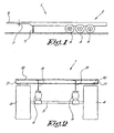
- figure 1 schematically represents a side view of a known semi-trailer;
- figure 2 represents a rear view of the semi-trailer according to figure 1 to a larger scale;
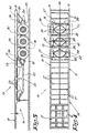
- figure 3 schematically represents a side view of an improved semi-trailer according to the invention;
- figure 4 represents a top view of the improved semi-trailer according to figure 3;
- figure 5 represents the part indicated by F5 in figure 4 to a larger scale;
- figure 6 is a section according to line VI-VI in figure 5;
- figure 7 represents a section according to line VII-VII in figure 5 to a larger scale;
- figure 8 represents a view in perspective of the part indicated by F8 in figure 7;
- figure 9 represents a section according to line IX-IX in figure 5 to a larger scale;
- figure 10 represents a section according to line X-X in figure 9;
- figures 11 to 14 schematically represent some variants of figure 6;
- figure 15 represents a view as in figure 3 to a smaller scale, but for a semi-trailer for containers;
- figure 16 represents a top view of the semi-trailer from figure 15;
- figures 17 and 18 represent variants of the semi-trailer according to figure 15.
- Figures 1 and 2 represent a semi-trailer 1 of a known type by way of example, with a chassis 2 which in this case is suspended at the back on three rigid axles 3 with some
wheels 4 and which is provided with ground props 5 in front with which the semi-trailer 1, as represented in figure 1, as separate from a lorry, can be erected in a parking place or the like, and which is equipped with acoupling element 7 on the journal 6 of thesemi-trailer 1 with which thesemi-trailer 1 can be coupled to a lorry in a hingeable manner. - The chassis 2 of this known semi-trailer, as is usual, is formed of two parallel
longitudinal runners 8 in the shape of two heavy I-profiles which are provided on the rigid axles 3 by means ofsprings 9 and which are connected to each other by means ofcross profiles 10 extending on either side of the chassis 2 and onto which are fixed two edge profiles 11 on the side edges of the chassis 2 in between which is provided aloading floor 12. - The above-mentioned I-profiles in this case have a constant section, save in the front part forming the journal 6 of the chassis, where the I-profile is less high.
- Figures 3 to 6 represent an improved
semi-trailer 13 according to the invention with comparable dimensions and the same number of wheel axles as the above-described knownconventional semi-trailer 1, but in this case with independently suspendedwheels 4. - The
chassis 14 of this semi-trailer 13 is in this case also formed of two parallellongitudinal runners 15 which are connected to each other by means of cross connections 16-17-18, whereby theselongitudinal runners 15 are not provided between thewheels 4 according to the invention, but on the side edges of thechassis 14, at a distance which is larger than the lateral clearance between the wheels, and whereby theselongitudinal runners 15 also form edge profiles onto which can be fixed a non-represented loading floor and/or a superstructure, and upon which can also be provided points of attachment for lashing down loads or the like. - Every
longitudinal runner 15 is formed of aprofile 19 according to the invention, for example a C-profile or a welded I-profile as represented, and of a reinforcement in the shape of a flat box-like construction 20 extending over a certain length in a central part of thelongitudinal runner 15, which part is mainly situated between thewheels 4 and thejournal 21, where the bending moments caused by the loads are the largest. - Thanks to said box-like construction, the moment of inertia of the longitudinal runner is locally enlarged, such that a larger resistance against bending is obtained.
- The box-
like construction 20 extends downward as of the I-profile 19 and is formed of the I-profile 19 itself and aprofile 22 running parallel to it which is connected to the I-profile 19 by means ofprofiles 23. - In this configuration, every
longitudinal runner 15 can be made much lighter than a correspondinglongitudinal runner 8 of the above-described knownsemi-trailer 1, such that thechassis 14 as a whole, partly thanks to the fact that no extra edge profiles 11 are required in this case, can be made considerably lighter than the chassis 2 of a comparable knownsemi-trailer 1. - In the middle of the
chassis 14, between thewheels 4, is provided acentral support 24 which in this case is formed of two centrallongitudinal profiles longitudinal runners 15 by means of two slantingly rising profiles, 27-28 and 29-30 respectively, of thecross connections 18. - In the given example, the
cross connections 18 on either side of eachwheel 4 are formed of V-shaped box-like constructions which mainly consist of the above-mentioned profiles 27-28-29-30 which are connected to each other by means ofprofiles 31. - Every
wheel 4 is independently suspended onto thechassis 14 by means of two parallel supporting arms, 32 and 33 respectively, which are hinge-mounted between the above-mentioned longitudinal profiles 25-26 and a supportingplate 34 for thewheel 4 concerned, in particular a supportingplate 34 in which the wheel stub is provided. - Every supporting arm 32-33 is mainly formed of two
hinge joints 35 which, as is represented in figures 7 and 8, are fixed onsupports 38 on one of either longitudinal profiles 25-26 with theirhinge pin 37, as well as by means of athird hinge joint 39 which is connected to the above-saidhinge joints 35 by means of tworods 40 in a triangular bracing and whosehinge pin 41, as represented in figures 9 and 10, is fixed to the above-mentioned supportingplate 34 by means ofbolts 42, which is provided with a forked part with twolegs 43 at the top and at the bottom to this end, in between which thehinge joint 39 concerned of a lower supportingarm 32 or of a top supportingarm 33 is provided. - Although, in the figures, the
hinge joints 35 have coaxial axes, it is not excluded for thehinge joints 35 to be mounted at an angle in relation to each other. - Between the moving supporting arms 32-33 and the
chassis 14 is provided asuspension 44, for example in the shape of a known pneumatic or hydraulic suspension. - The vertical distance between the hinge joints on one and the same supporting
plate 34 is preferably equal to the vertical distance between thehinge joints 35 on the supports formed of the lower and the top longitudinal profile 25-26, such that the supporting arms 25-26 always remain parallel to each other, and thewheel 4 attached to it stays mainly parallel to itself. - Thanks to the independent suspension of the
wheels 4 in the shape of parallel supporting arms 32-33, a major additional weight saving can be obtained in relation to the above-mentioned known semi-trailer 1 with rigid wheel axles 3, and the semi-trailer 13 will moreover be more stable as thewheels 4 keep better contact with the ground. - It is clear that on the
longitudinal profiles 15 can be provided a loading floor, not represented in the figures, which rests for example on the cross connections 16-17. - Figure 11 represents a variant of a
semi-trailer 13 according to the invention which in this case is embodied with abucket 45 whosebottom 46 is made trough-shaped, and whereby thisbottom 46 is mainly provided between thelongitudinal runners 15. - It is clear from figure 11 that, in this case, the
bucket 45 can be brought considerably closer to the ground than in the case of aconventional semi-trailer 1 whereby the bucket is provided directly on thelongitudinal runners 8, as is schematically represented by means of a dashed line. - As a result, the centre of gravity of the
bucket 45 is pulled down compared to a conventional tipping trailer, as a result of which a tipping trailer according to the invention will behave in a more stable manner during transport. - It is clear that, in this case, the cross connections 17-18 must have a concave form over a certain length of the semi-trailer 13, so that a bed is formed so to say in which the
bucket 45 fits. - Figure 12 represents another variant of a
semi-trailer 13 according to the invention, in particular asemi-trailer 13 for a tank 50 for the transport of liquids or bulk goods. - In this case, the cross connections 17-18 are formed of two profiles 47 with which a
longitudinal profile 48 is fixed to thelongitudinal runners 15, and whereby across connection 49 is provided between the profiles 47. - The
longitudinal profile 48 and thecross connection 49 in this case form the above-mentionedcentral support 24 upon which the supporting arms 32-33 are fixed with theirhinge joints 35. - As appears from the figure, the centre of gravity of the tank 50 is situated considerably lower than that of a tank of a comparable known
semi-trailer 1 represented by means of a dashed line. - Figure 13 represents another variant whereby the
semi-trailer 13 is provided with acrane 51 provided on a vehicle 52 whosewheels 53 can move on thelongitudinal runners 15. - In this case also, a considerable weight saving is obtained since no special rails must be provided as is the case with the known
semi-trailers 13. - Figure 14 represents a
semi-trailer 13 for the transport ofcoils 54 of paper, metal or the like, which in this case also can be provided lower to the ground than in the case of the known semi-trailers, as represented by means of a dashed line. - The cross connections 17-18 are in this case formed of predominantly sickle-shaped I-profiles 55 with a predominantly sickle-shaped
invert plate 56 in which are providedholes 57 in order to save weight. Also a I-profile bent in the shape of a U could be used to this end. - Figures 15 and 16 represent a variant for an application as a
semi-trailer 13 for a container, whereby what are called twist-lock couplings 58 are in this case provided on thelongitudinal runners 15 for fastening a container. - In this case, no extra heavy cross profiles 11 must be provided for fastening the above-mentioned
couplings 58, which implies an extra weight saving and which considerably simplifies the construction of such a container trailer. - Figure 17 represents a variant whereby the box-
like constructions 20 are used as a frame in this case for applying plates or the like to mark out storage rooms to store empty pallets 59, tools, a spare wheel or the like in, and whereby these compartments can be either or not provided with alockable access hatch 60 or the like. - Figure 18 represents a final variant whereby the box-like construction is made with a bent I-profile 61.
- Although in the figures, the
wheels 4 are tracking wheels, it is not excluded for asemi-trailer 13 according to the invention to be equipped with driven wheels by replacing the above-mentionedwheel hubs 34 by hinge-mounted stub axles which are connected to hydraulic, pneumatic or other controls by means of rods. - The invention is by no means limited to the above-described embodiments given as an example and represented in the accompanying drawings; on the contrary, such an improved semi-trailer according to the invention can be made in all sorts of shapes and dimensions while still remaining within the scope of the invention as defined by the accompanying claims.
Claims (12)
- Semi-trailer which mainly consists of a chassis (14) with at least two supporting longitudinal runners (15), connected to each other by means of cross connections (16-17-18), and two or several single or double wheels (4) carrying the chassis (14) such that wheels (4) are located on either side of the chassis defining a lateral clearance therebetween, whereby the longitudinal runners (15) are situated on the side edges of the chassis (14) at a distance from each other which is larger than the lateral clearance between the wheels (4), characterized in that every wheel (4) is fixed independently of the other wheels (4) on the chassis (14) by means of two parallel supporting arms (32-33) which are provided in pairs on the chassis (14), on top of each other and at a vertical distance from each other and which supporting arms (32-33) are hinge-mounted at their far ends on a central longitudinal directed support (24) which is part of the chassis (14).
- Semi-trailer according to claim 1, characterised in that each above-mentioned longitudinal runner (15) on the side edge of the chassis (14) is formed of an I-profile (19) which is provided with a reinforcement in the shape of a box-like construction (20) over a certain length.
- Semi-trailer according to claim 2, characterised in that the above-mentioned box-like construction (20) mainly extends between the wheels (4) and the journal (21) of the semi-trailer (13).
- Semi-trailer according to claim 3, characterised in that the above-mentioned box-like construction (20) extends downward in relation to the above-mentioned I-profile (19).
- Semi-trailer according to claim 1, characterised in that the above-mentioned support is formed of two longitudinal profiles (25-26) situated at different heights, fixed on the above-mentioned cross connections (18).
- Semi-trailer according to claim 1 or 5, characterised in that every supporting arm (32-33) is mainly formed of three hinge joints (35-39) which are connected to each other by means of two rods (40) in a triangular bracing.
- Semi-trailer according to claim 5,
characterised in that one or several of the above-mentioned cross connections (17-18) have a concave shape. - Semi-trailer according to claim 7, characterised in that the above-mentioned cross connections (17-18) are formed of a box-like construction.
- Semi-trailer according to claim 7, characterised in that the above-mentioned cross connections (17-18) are formed of a predominantly sickle-shaped I-profile (55).
- Semi-trailer according to claim 1, characterised in that in the case of semi-trailers (13) with several axles, a cross connection (18) is provided at least between each pair of adjacent wheel axles upon which the above-mentioned central support for the supporting arms (32-33) is fixed.
- Semi-trailer according to claim 1, characterised in that it is provided with a loading floor whose edge profiles are formed of the above-mentioned longitudinal runners (15) on the side edges of the chassis (14).
- Semi-trailer according to claim 1, characterised in that it is provided with what are called twist-lock couplings (58) for fastening a container, which couplings (58) are provided on the supporting longitudinal runners (15) on the side edges of the chassis (14).
Applications Claiming Priority (3)
| Application Number | Priority Date | Filing Date | Title |
|---|---|---|---|
| BE200300130 | 2003-02-27 | ||
| BE2003/0130A BE1015391A3 (en) | 2003-02-27 | 2003-02-27 | Improved trailer. |
| PCT/BE2004/000025 WO2004076263A1 (en) | 2003-02-27 | 2004-02-25 | Semi-trailer chassis and wheel suspension |
Publications (2)
| Publication Number | Publication Date |
|---|---|
| EP1597134A1 EP1597134A1 (en) | 2005-11-23 |
| EP1597134B1 true EP1597134B1 (en) | 2007-01-17 |
Family
ID=32913552
Family Applications (1)
| Application Number | Title | Priority Date | Filing Date |
|---|---|---|---|
| EP04714245A Expired - Lifetime EP1597134B1 (en) | 2003-02-27 | 2004-02-25 | Semi-trailer chassis and wheel suspension |
Country Status (7)
| Country | Link |
|---|---|
| US (1) | US20060055141A1 (en) |
| EP (1) | EP1597134B1 (en) |
| CN (1) | CN100431899C (en) |
| BE (1) | BE1015391A3 (en) |
| DE (1) | DE602004004373T2 (en) |
| ES (1) | ES2280946T3 (en) |
| WO (1) | WO2004076263A1 (en) |
Cited By (2)
| Publication number | Priority date | Publication date | Assignee | Title |
|---|---|---|---|---|
| EP1985474A3 (en) * | 2007-04-25 | 2010-02-10 | Doll Fahrzeugbau AG | Semi-trailer |
| RU168306U1 (en) * | 2016-08-30 | 2017-01-30 | Общество с ограниченной ответственностью "ПромТранспортСервис" | SEMITRAILER |
Families Citing this family (17)
| Publication number | Priority date | Publication date | Assignee | Title |
|---|---|---|---|---|
| JP4893429B2 (en) * | 2007-04-04 | 2012-03-07 | 日産自動車株式会社 | Suspension device |
| US20090058133A1 (en) * | 2007-09-05 | 2009-03-05 | Great Dane Limited Partnership | Method of undercoating a suspension and undercarriage area |
| CN101269616B (en) * | 2007-09-21 | 2010-05-26 | 上汽通用五菱汽车股份有限公司 | Integration type arm swing support device and assembly method thereof |
| RU2376186C1 (en) * | 2008-04-04 | 2009-12-20 | Открытое акционерное общество "КАМАЗ" | Vehicle frame |
| NL2006484C2 (en) * | 2011-03-29 | 2012-10-02 | Transp Industry Dev Ct Bv | TRAILER FOR A TRUCK COMBINATION, AND WHEEL SUSPENSION FOR SUCH TRAILER. |
| CN102975772B (en) * | 2012-11-16 | 2015-05-13 | 中国煤炭科工集团太原研究院 | Underground coal mine four-wheel double-hinge-point swing type hinged frame structure |
| US9022402B1 (en) | 2014-02-04 | 2015-05-05 | Atieva, Inc. | Compact rear suspension damper-spring assembly |
| US9022401B1 (en) | 2014-02-04 | 2015-05-05 | Atieva, Inc. | Compact rear suspension damper-spring assembly |
| US9073397B1 (en) | 2014-02-04 | 2015-07-07 | Atieva, Inc. | Compact rear suspension damper-spring assembly |
| US8905416B1 (en) * | 2014-02-04 | 2014-12-09 | Atieva, Inc. | Compact rear suspension damper-spring assembly |
| DE102015113973B4 (en) * | 2015-08-24 | 2020-06-18 | Saf-Holland Gmbh | Frame arrangement |
| DE202016101503U1 (en) * | 2016-03-18 | 2017-06-20 | August Alborn Gmbh & Co. Kg | Construction crane and body crane system |
| CN109906156A (en) * | 2016-08-22 | 2019-06-18 | 斯太姆科产品公司 | Double yoke independence trailer suspensions |
| JP2018127069A (en) * | 2017-02-07 | 2018-08-16 | 日鉄住金物流鹿島株式会社 | Trailer |
| ES2786565T3 (en) * | 2017-06-07 | 2020-10-13 | August Alborn Gmbh & Co Kg | Construction crane and construction crane system |
| CN110065576A (en) * | 2019-04-25 | 2019-07-30 | 潍坊红石星机械加工有限公司 | Electro-tricycle suspension fork mechanism |
| DE102019127946B4 (en) | 2019-10-16 | 2023-02-02 | Saf-Holland Gmbh | Axle alignment system |
Family Cites Families (24)
| Publication number | Priority date | Publication date | Assignee | Title |
|---|---|---|---|---|
| US1731962A (en) * | 1927-12-08 | 1929-10-15 | James A Wright | Rear-axle assembly |
| US2846263A (en) * | 1955-07-08 | 1958-08-05 | Kaiser Aluminium Chem Corp | Vehicle |
| US3012795A (en) * | 1958-11-26 | 1961-12-12 | Carl F Doerfier | Vertically adjustable pneumatic suspension for boat trailer |
| US3179439A (en) * | 1961-08-15 | 1965-04-20 | Robert N Janeway | Trailer suspension |
| US3356386A (en) * | 1965-10-20 | 1967-12-05 | Taylor Ralph Wendell | Underslung wheel suspension systems |
| US3788683A (en) * | 1972-07-10 | 1974-01-29 | J Rumell | Transport vehicle with portable cargo container |
| US4050709A (en) * | 1976-01-19 | 1977-09-27 | Leboeuf Eugene A | Trailer deflector ramp |
| DE2627847C3 (en) * | 1976-06-22 | 1982-11-25 | Dr.Ing.H.C. F. Porsche Ag, 7000 Stuttgart | Front suspension for automobiles |
| US4129395A (en) * | 1977-07-05 | 1978-12-12 | Theurer Atlantic Incorporated | Container lock assembly |
| US4930809A (en) * | 1988-01-11 | 1990-06-05 | Lindsay Industries, Inc. | Towable unified floor frame assembly |
| US4863189A (en) * | 1988-01-11 | 1989-09-05 | Lindsay Industries, Inc. | Unified floor frame assembly for modular mobile home |
| US4971355A (en) * | 1989-08-25 | 1990-11-20 | Continental Conveyor & Equipment Co., Inc. | Mobile home chassis |
| US5242185A (en) * | 1992-03-09 | 1993-09-07 | Fruehauf Trailer Corporation | Shallow nose platform trailer |
| US5820150A (en) * | 1993-04-14 | 1998-10-13 | Oshkosh Truck Corporation | Independent suspensions for lowering height of vehicle frame |
| DE9306171U1 (en) * | 1993-04-23 | 1993-06-09 | MAN Nutzfahrzeuge AG, 8000 München | Floor frame cross member in a bus |
| US5401050A (en) * | 1993-06-04 | 1995-03-28 | Baker; James H. | Machinery transport trailer |
| CN1037948C (en) * | 1993-09-11 | 1998-04-08 | 兹普林车辆系统公司 | truck |
| CN2223232Y (en) * | 1995-03-13 | 1996-03-27 | 中汽专用汽车烟台绍宇汽车股份有限公司 | Micro-frame for vehicle |
| DE19638465C2 (en) * | 1996-09-19 | 2000-05-25 | Orthaus Fahrzeugwerk | Innenlader trucks for container transport |
| US6109684A (en) * | 1998-03-16 | 2000-08-29 | Reitnouer; Miles A. | Unitized flatbed trailer structure and container truck floor structure |
| DE10004227A1 (en) * | 2000-02-01 | 2001-08-02 | Bpw Bergische Achsen Kg | Wheel suspension for vehicles, in particular commercial vehicle trailers |
| EP1127749A3 (en) * | 2000-02-24 | 2005-12-14 | SCHIMMELPFENNIG, Karl-Heinz | Protection frame for road vehicles |
| DE10035273C1 (en) * | 2000-05-22 | 2001-10-18 | Schimmelpfennig Karl Heinz | Protective frame arrangement for support frame, for vehicle, has horizontal bars to cover wheels, which are arranged with individual wheel suspensions, where steerable wheels have curved wheel supports |
| ATE340750T1 (en) * | 2000-10-02 | 2006-10-15 | Philip Tomkins | TRANSPORT BACKING FRAME |
-
2003
- 2003-02-27 BE BE2003/0130A patent/BE1015391A3/en not_active IP Right Cessation
-
2004
- 2004-02-25 EP EP04714245A patent/EP1597134B1/en not_active Expired - Lifetime
- 2004-02-25 CN CNB2004800052458A patent/CN100431899C/en not_active Expired - Fee Related
- 2004-02-25 WO PCT/BE2004/000025 patent/WO2004076263A1/en not_active Ceased
- 2004-02-25 US US10/544,130 patent/US20060055141A1/en not_active Abandoned
- 2004-02-25 DE DE602004004373T patent/DE602004004373T2/en not_active Expired - Lifetime
- 2004-02-25 ES ES04714245T patent/ES2280946T3/en not_active Expired - Lifetime
Cited By (3)
| Publication number | Priority date | Publication date | Assignee | Title |
|---|---|---|---|---|
| EP1985474A3 (en) * | 2007-04-25 | 2010-02-10 | Doll Fahrzeugbau AG | Semi-trailer |
| DE202008017914U1 (en) | 2007-04-25 | 2010-10-28 | Doll Fahrzeugbau Ag | semitrailer |
| RU168306U1 (en) * | 2016-08-30 | 2017-01-30 | Общество с ограниченной ответственностью "ПромТранспортСервис" | SEMITRAILER |
Also Published As
| Publication number | Publication date |
|---|---|
| CN1753806A (en) | 2006-03-29 |
| CN100431899C (en) | 2008-11-12 |
| BE1015391A3 (en) | 2005-03-01 |
| DE602004004373T2 (en) | 2007-10-18 |
| WO2004076263B1 (en) | 2004-11-04 |
| US20060055141A1 (en) | 2006-03-16 |
| WO2004076263A1 (en) | 2004-09-10 |
| DE602004004373D1 (en) | 2007-03-08 |
| ES2280946T3 (en) | 2007-09-16 |
| WO2004076263A8 (en) | 2005-04-14 |
| EP1597134A1 (en) | 2005-11-23 |
Similar Documents
| Publication | Publication Date | Title |
|---|---|---|
| EP1597134B1 (en) | Semi-trailer chassis and wheel suspension | |
| US5476285A (en) | Suspension system and body for large dump trucks | |
| US5611570A (en) | Unibeam trailer chassis | |
| US5482356A (en) | Rear dump trailer | |
| US20040036245A1 (en) | Suspension system and body for large dump trucks | |
| US5039124A (en) | Motor vehicle frame and suspension assembly | |
| US8235403B2 (en) | Suspension assembly | |
| CA2457004C (en) | Front loading trailer and method of use | |
| US5951032A (en) | Air suspension system | |
| US3214047A (en) | Trailer | |
| EP1577159B1 (en) | Trailer having pivoted axles and a central recess | |
| CA2044127C (en) | Dumping semi-trailer | |
| US9381846B2 (en) | Haul bodies and related apparatus | |
| US2239442A (en) | Vehicle tank | |
| CA2058661A1 (en) | Road vehicle having a rear dump box | |
| GB1601320A (en) | Delivery vehicles | |
| SU1703512A1 (en) | Dump truck | |
| CN221541725U (en) | Novel chassis frame structure of semitrailer | |
| GB2251827A (en) | Foldable trailers | |
| EP1053930A1 (en) | Vehicle | |
| AU2013201290B2 (en) | Improvements to haul bodies | |
| AU670445B2 (en) | Road vehicle trailer | |
| SU1562209A1 (en) | Three-unit semitrailer for road train | |
| EP0096437A2 (en) | Suspension system for vehicles | |
| WO2019053587A1 (en) | An improved semi-trailer |
Legal Events
| Date | Code | Title | Description |
|---|---|---|---|
| PUAI | Public reference made under article 153(3) epc to a published international application that has entered the european phase |
Free format text: ORIGINAL CODE: 0009012 |
|
| 17P | Request for examination filed |
Effective date: 20050801 |
|
| AK | Designated contracting states |
Kind code of ref document: A1 Designated state(s): AT BE BG CH CY CZ DE DK EE ES FI FR GB GR HU IE IT LI LU MC NL PT RO SE SI SK TR |
|
| AX | Request for extension of the european patent |
Extension state: AL LT LV MK |
|
| DAX | Request for extension of the european patent (deleted) | ||
| GRAP | Despatch of communication of intention to grant a patent |
Free format text: ORIGINAL CODE: EPIDOSNIGR1 |
|
| GRAS | Grant fee paid |
Free format text: ORIGINAL CODE: EPIDOSNIGR3 |
|
| GRAA | (expected) grant |
Free format text: ORIGINAL CODE: 0009210 |
|
| AK | Designated contracting states |
Kind code of ref document: B1 Designated state(s): AT BE BG CH CY CZ DE DK EE ES FI FR GB GR HU IE IT LI LU MC NL PT RO SE SI SK TR |
|
| PG25 | Lapsed in a contracting state [announced via postgrant information from national office to epo] |
Ref country code: AT Free format text: LAPSE BECAUSE OF FAILURE TO SUBMIT A TRANSLATION OF THE DESCRIPTION OR TO PAY THE FEE WITHIN THE PRESCRIBED TIME-LIMIT Effective date: 20070117 Ref country code: LI Free format text: LAPSE BECAUSE OF FAILURE TO SUBMIT A TRANSLATION OF THE DESCRIPTION OR TO PAY THE FEE WITHIN THE PRESCRIBED TIME-LIMIT Effective date: 20070117 Ref country code: DK Free format text: LAPSE BECAUSE OF FAILURE TO SUBMIT A TRANSLATION OF THE DESCRIPTION OR TO PAY THE FEE WITHIN THE PRESCRIBED TIME-LIMIT Effective date: 20070117 Ref country code: CH Free format text: LAPSE BECAUSE OF FAILURE TO SUBMIT A TRANSLATION OF THE DESCRIPTION OR TO PAY THE FEE WITHIN THE PRESCRIBED TIME-LIMIT Effective date: 20070117 Ref country code: SI Free format text: LAPSE BECAUSE OF FAILURE TO SUBMIT A TRANSLATION OF THE DESCRIPTION OR TO PAY THE FEE WITHIN THE PRESCRIBED TIME-LIMIT Effective date: 20070117 Ref country code: FI Free format text: LAPSE BECAUSE OF FAILURE TO SUBMIT A TRANSLATION OF THE DESCRIPTION OR TO PAY THE FEE WITHIN THE PRESCRIBED TIME-LIMIT Effective date: 20070117 |
|
| REG | Reference to a national code |
Ref country code: GB Ref legal event code: FG4D |
|
| REG | Reference to a national code |
Ref country code: CH Ref legal event code: EP |
|
| PG25 | Lapsed in a contracting state [announced via postgrant information from national office to epo] |
Ref country code: MC Free format text: LAPSE BECAUSE OF NON-PAYMENT OF DUE FEES Effective date: 20070228 |
|
| REG | Reference to a national code |
Ref country code: IE Ref legal event code: FG4D |
|
| REF | Corresponds to: |
Ref document number: 602004004373 Country of ref document: DE Date of ref document: 20070308 Kind code of ref document: P |
|
| PG25 | Lapsed in a contracting state [announced via postgrant information from national office to epo] |
Ref country code: BG Free format text: LAPSE BECAUSE OF FAILURE TO SUBMIT A TRANSLATION OF THE DESCRIPTION OR TO PAY THE FEE WITHIN THE PRESCRIBED TIME-LIMIT Effective date: 20070417 |
|
| REG | Reference to a national code |
Ref country code: SE Ref legal event code: TRGR |
|
| PG25 | Lapsed in a contracting state [announced via postgrant information from national office to epo] |
Ref country code: PT Free format text: LAPSE BECAUSE OF FAILURE TO SUBMIT A TRANSLATION OF THE DESCRIPTION OR TO PAY THE FEE WITHIN THE PRESCRIBED TIME-LIMIT Effective date: 20070618 |
|
| ET | Fr: translation filed | ||
| REG | Reference to a national code |
Ref country code: CH Ref legal event code: PL |
|
| REG | Reference to a national code |
Ref country code: ES Ref legal event code: FG2A Ref document number: 2280946 Country of ref document: ES Kind code of ref document: T3 |
|
| PLBE | No opposition filed within time limit |
Free format text: ORIGINAL CODE: 0009261 |
|
| STAA | Information on the status of an ep patent application or granted ep patent |
Free format text: STATUS: NO OPPOSITION FILED WITHIN TIME LIMIT |
|
| PG25 | Lapsed in a contracting state [announced via postgrant information from national office to epo] |
Ref country code: SK Free format text: LAPSE BECAUSE OF FAILURE TO SUBMIT A TRANSLATION OF THE DESCRIPTION OR TO PAY THE FEE WITHIN THE PRESCRIBED TIME-LIMIT Effective date: 20070117 |
|
| 26N | No opposition filed |
Effective date: 20071018 |
|
| PG25 | Lapsed in a contracting state [announced via postgrant information from national office to epo] |
Ref country code: CZ Free format text: LAPSE BECAUSE OF FAILURE TO SUBMIT A TRANSLATION OF THE DESCRIPTION OR TO PAY THE FEE WITHIN THE PRESCRIBED TIME-LIMIT Effective date: 20070117 Ref country code: RO Free format text: LAPSE BECAUSE OF FAILURE TO SUBMIT A TRANSLATION OF THE DESCRIPTION OR TO PAY THE FEE WITHIN THE PRESCRIBED TIME-LIMIT Effective date: 20070117 |
|
| PG25 | Lapsed in a contracting state [announced via postgrant information from national office to epo] |
Ref country code: IE Free format text: LAPSE BECAUSE OF NON-PAYMENT OF DUE FEES Effective date: 20070226 |
|
| PG25 | Lapsed in a contracting state [announced via postgrant information from national office to epo] |
Ref country code: GR Free format text: LAPSE BECAUSE OF FAILURE TO SUBMIT A TRANSLATION OF THE DESCRIPTION OR TO PAY THE FEE WITHIN THE PRESCRIBED TIME-LIMIT Effective date: 20070418 |
|
| PG25 | Lapsed in a contracting state [announced via postgrant information from national office to epo] |
Ref country code: EE Free format text: LAPSE BECAUSE OF FAILURE TO SUBMIT A TRANSLATION OF THE DESCRIPTION OR TO PAY THE FEE WITHIN THE PRESCRIBED TIME-LIMIT Effective date: 20070117 |
|
| PGFP | Annual fee paid to national office [announced via postgrant information from national office to epo] |
Ref country code: ES Payment date: 20090206 Year of fee payment: 6 |
|
| PGFP | Annual fee paid to national office [announced via postgrant information from national office to epo] |
Ref country code: NL Payment date: 20090227 Year of fee payment: 6 |
|
| PGFP | Annual fee paid to national office [announced via postgrant information from national office to epo] |
Ref country code: GB Payment date: 20090217 Year of fee payment: 6 |
|
| PG25 | Lapsed in a contracting state [announced via postgrant information from national office to epo] |
Ref country code: CY Free format text: LAPSE BECAUSE OF FAILURE TO SUBMIT A TRANSLATION OF THE DESCRIPTION OR TO PAY THE FEE WITHIN THE PRESCRIBED TIME-LIMIT Effective date: 20070117 |
|
| PGFP | Annual fee paid to national office [announced via postgrant information from national office to epo] |
Ref country code: BE Payment date: 20090129 Year of fee payment: 6 |
|
| PG25 | Lapsed in a contracting state [announced via postgrant information from national office to epo] |
Ref country code: LU Free format text: LAPSE BECAUSE OF NON-PAYMENT OF DUE FEES Effective date: 20070225 |
|
| PGFP | Annual fee paid to national office [announced via postgrant information from national office to epo] |
Ref country code: IT Payment date: 20090226 Year of fee payment: 6 Ref country code: SE Payment date: 20090225 Year of fee payment: 6 Ref country code: TR Payment date: 20090225 Year of fee payment: 6 |
|
| PG25 | Lapsed in a contracting state [announced via postgrant information from national office to epo] |
Ref country code: HU Free format text: LAPSE BECAUSE OF FAILURE TO SUBMIT A TRANSLATION OF THE DESCRIPTION OR TO PAY THE FEE WITHIN THE PRESCRIBED TIME-LIMIT Effective date: 20070718 |
|
| PGFP | Annual fee paid to national office [announced via postgrant information from national office to epo] |
Ref country code: FR Payment date: 20090202 Year of fee payment: 6 |
|
| REG | Reference to a national code |
Ref country code: GB Ref legal event code: S117 Free format text: REQUEST FILED; REQUEST FOR CORRECTION UNDER SECTION 117 FILED ON 5 NOVEMBER 2009 |
|
| REG | Reference to a national code |
Ref country code: GB Ref legal event code: S117 Free format text: CORRECTIONS ALLOWED |
|
| BERE | Be: lapsed |
Owner name: TG CONSULTING, B.V. MET BEPERKTE AANSPRAKELIJKHEI Effective date: 20100228 |
|
| REG | Reference to a national code |
Ref country code: NL Ref legal event code: V1 Effective date: 20100901 |
|
| EUG | Se: european patent has lapsed | ||
| GBPC | Gb: european patent ceased through non-payment of renewal fee |
Effective date: 20100225 |
|
| REG | Reference to a national code |
Ref country code: FR Ref legal event code: ST Effective date: 20101029 |
|
| PG25 | Lapsed in a contracting state [announced via postgrant information from national office to epo] |
Ref country code: FR Free format text: LAPSE BECAUSE OF NON-PAYMENT OF DUE FEES Effective date: 20100301 Ref country code: NL Free format text: LAPSE BECAUSE OF NON-PAYMENT OF DUE FEES Effective date: 20100901 |
|
| PG25 | Lapsed in a contracting state [announced via postgrant information from national office to epo] |
Ref country code: BE Free format text: LAPSE BECAUSE OF NON-PAYMENT OF DUE FEES Effective date: 20100228 |
|
| REG | Reference to a national code |
Ref country code: ES Ref legal event code: FD2A Effective date: 20110325 |
|
| PG25 | Lapsed in a contracting state [announced via postgrant information from national office to epo] |
Ref country code: IT Free format text: LAPSE BECAUSE OF NON-PAYMENT OF DUE FEES Effective date: 20100225 Ref country code: GB Free format text: LAPSE BECAUSE OF NON-PAYMENT OF DUE FEES Effective date: 20100225 |
|
| PG25 | Lapsed in a contracting state [announced via postgrant information from national office to epo] |
Ref country code: ES Free format text: LAPSE BECAUSE OF NON-PAYMENT OF DUE FEES Effective date: 20110314 |
|
| PGFP | Annual fee paid to national office [announced via postgrant information from national office to epo] |
Ref country code: DE Payment date: 20110423 Year of fee payment: 8 |
|
| PG25 | Lapsed in a contracting state [announced via postgrant information from national office to epo] |
Ref country code: ES Free format text: LAPSE BECAUSE OF NON-PAYMENT OF DUE FEES Effective date: 20100226 |
|
| PG25 | Lapsed in a contracting state [announced via postgrant information from national office to epo] |
Ref country code: SE Free format text: LAPSE BECAUSE OF NON-PAYMENT OF DUE FEES Effective date: 20100226 |
|
| REG | Reference to a national code |
Ref country code: DE Ref legal event code: R119 Ref document number: 602004004373 Country of ref document: DE Effective date: 20120901 |
|
| PG25 | Lapsed in a contracting state [announced via postgrant information from national office to epo] |
Ref country code: TR Free format text: LAPSE BECAUSE OF NON-PAYMENT OF DUE FEES Effective date: 20100225 |
|
| PG25 | Lapsed in a contracting state [announced via postgrant information from national office to epo] |
Ref country code: DE Free format text: LAPSE BECAUSE OF NON-PAYMENT OF DUE FEES Effective date: 20120901 |