EP1597016B1 - Safety mechanism for materials handling system - Google Patents
Safety mechanism for materials handling system Download PDFInfo
- Publication number
- EP1597016B1 EP1597016B1 EP04712424A EP04712424A EP1597016B1 EP 1597016 B1 EP1597016 B1 EP 1597016B1 EP 04712424 A EP04712424 A EP 04712424A EP 04712424 A EP04712424 A EP 04712424A EP 1597016 B1 EP1597016 B1 EP 1597016B1
- Authority
- EP
- European Patent Office
- Prior art keywords
- lock
- lock shaft
- shaft
- coupling
- collar
- Prior art date
- Legal status (The legal status is an assumption and is not a legal conclusion. Google has not performed a legal analysis and makes no representation as to the accuracy of the status listed.)
- Expired - Lifetime
Links
- 230000007246 mechanism Effects 0.000 title description 10
- 238000005007 materials handling Methods 0.000 title description 8
- 230000008878 coupling Effects 0.000 claims abstract description 93
- 238000010168 coupling process Methods 0.000 claims abstract description 93
- 238000005859 coupling reaction Methods 0.000 claims abstract description 93
- 238000012360 testing method Methods 0.000 claims description 37
- 238000000034 method Methods 0.000 claims description 8
- 230000006835 compression Effects 0.000 description 8
- 238000007906 compression Methods 0.000 description 8
- 230000002093 peripheral effect Effects 0.000 description 6
- 230000002265 prevention Effects 0.000 description 3
- 230000000694 effects Effects 0.000 description 2
- 230000003993 interaction Effects 0.000 description 2
- 230000015556 catabolic process Effects 0.000 description 1
- 238000006731 degradation reaction Methods 0.000 description 1
- 238000004519 manufacturing process Methods 0.000 description 1
- 238000003032 molecular docking Methods 0.000 description 1
Images





Classifications
-
- F—MECHANICAL ENGINEERING; LIGHTING; HEATING; WEAPONS; BLASTING
- F16—ENGINEERING ELEMENTS AND UNITS; GENERAL MEASURES FOR PRODUCING AND MAINTAINING EFFECTIVE FUNCTIONING OF MACHINES OR INSTALLATIONS; THERMAL INSULATION IN GENERAL
- F16C—SHAFTS; FLEXIBLE SHAFTS; ELEMENTS OR CRANKSHAFT MECHANISMS; ROTARY BODIES OTHER THAN GEARING ELEMENTS; BEARINGS
- F16C29/00—Bearings for parts moving only linearly
- F16C29/02—Sliding-contact bearings
-
- B—PERFORMING OPERATIONS; TRANSPORTING
- B23—MACHINE TOOLS; METAL-WORKING NOT OTHERWISE PROVIDED FOR
- B23Q—DETAILS, COMPONENTS, OR ACCESSORIES FOR MACHINE TOOLS, e.g. ARRANGEMENTS FOR COPYING OR CONTROLLING; MACHINE TOOLS IN GENERAL CHARACTERISED BY THE CONSTRUCTION OF PARTICULAR DETAILS OR COMPONENTS; COMBINATIONS OR ASSOCIATIONS OF METAL-WORKING MACHINES, NOT DIRECTED TO A PARTICULAR RESULT
- B23Q1/00—Members which are comprised in the general build-up of a form of machine, particularly relatively large fixed members
- B23Q1/25—Movable or adjustable work or tool supports
- B23Q1/26—Movable or adjustable work or tool supports characterised by constructional features relating to the co-operation of relatively movable members; Means for preventing relative movement of such members
- B23Q1/28—Means for securing sliding members in any desired position
-
- B—PERFORMING OPERATIONS; TRANSPORTING
- B23—MACHINE TOOLS; METAL-WORKING NOT OTHERWISE PROVIDED FOR
- B23Q—DETAILS, COMPONENTS, OR ACCESSORIES FOR MACHINE TOOLS, e.g. ARRANGEMENTS FOR COPYING OR CONTROLLING; MACHINE TOOLS IN GENERAL CHARACTERISED BY THE CONSTRUCTION OF PARTICULAR DETAILS OR COMPONENTS; COMBINATIONS OR ASSOCIATIONS OF METAL-WORKING MACHINES, NOT DIRECTED TO A PARTICULAR RESULT
- B23Q1/00—Members which are comprised in the general build-up of a form of machine, particularly relatively large fixed members
- B23Q1/25—Movable or adjustable work or tool supports
- B23Q1/26—Movable or adjustable work or tool supports characterised by constructional features relating to the co-operation of relatively movable members; Means for preventing relative movement of such members
- B23Q1/28—Means for securing sliding members in any desired position
- B23Q1/285—Means for securing sliding members in any desired position for securing two or more members simultaneously or selectively
-
- B—PERFORMING OPERATIONS; TRANSPORTING
- B23—MACHINE TOOLS; METAL-WORKING NOT OTHERWISE PROVIDED FOR
- B23Q—DETAILS, COMPONENTS, OR ACCESSORIES FOR MACHINE TOOLS, e.g. ARRANGEMENTS FOR COPYING OR CONTROLLING; MACHINE TOOLS IN GENERAL CHARACTERISED BY THE CONSTRUCTION OF PARTICULAR DETAILS OR COMPONENTS; COMBINATIONS OR ASSOCIATIONS OF METAL-WORKING MACHINES, NOT DIRECTED TO A PARTICULAR RESULT
- B23Q5/00—Driving or feeding mechanisms; Control arrangements therefor
- B23Q5/54—Arrangements or details not restricted to group B23Q5/02 or group B23Q5/22 respectively, e.g. control handles
- B23Q5/58—Safety devices
- B23Q5/585—Preventing the misuse of accessories, e.g. chuck keys
-
- F—MECHANICAL ENGINEERING; LIGHTING; HEATING; WEAPONS; BLASTING
- F16—ENGINEERING ELEMENTS AND UNITS; GENERAL MEASURES FOR PRODUCING AND MAINTAINING EFFECTIVE FUNCTIONING OF MACHINES OR INSTALLATIONS; THERMAL INSULATION IN GENERAL
- F16C—SHAFTS; FLEXIBLE SHAFTS; ELEMENTS OR CRANKSHAFT MECHANISMS; ROTARY BODIES OTHER THAN GEARING ELEMENTS; BEARINGS
- F16C29/00—Bearings for parts moving only linearly
- F16C29/10—Arrangements for locking the bearings
-
- F—MECHANICAL ENGINEERING; LIGHTING; HEATING; WEAPONS; BLASTING
- F16—ENGINEERING ELEMENTS AND UNITS; GENERAL MEASURES FOR PRODUCING AND MAINTAINING EFFECTIVE FUNCTIONING OF MACHINES OR INSTALLATIONS; THERMAL INSULATION IN GENERAL
- F16C—SHAFTS; FLEXIBLE SHAFTS; ELEMENTS OR CRANKSHAFT MECHANISMS; ROTARY BODIES OTHER THAN GEARING ELEMENTS; BEARINGS
- F16C2322/00—Apparatus used in shaping articles
- F16C2322/39—General buildup of machine tools, e.g. spindles, slides, actuators
-
- Y—GENERAL TAGGING OF NEW TECHNOLOGICAL DEVELOPMENTS; GENERAL TAGGING OF CROSS-SECTIONAL TECHNOLOGIES SPANNING OVER SEVERAL SECTIONS OF THE IPC; TECHNICAL SUBJECTS COVERED BY FORMER USPC CROSS-REFERENCE ART COLLECTIONS [XRACs] AND DIGESTS
- Y10—TECHNICAL SUBJECTS COVERED BY FORMER USPC
- Y10T—TECHNICAL SUBJECTS COVERED BY FORMER US CLASSIFICATION
- Y10T70/00—Locks
- Y10T70/50—Special application
- Y10T70/5009—For portable articles
Definitions
- the present invention relates, in general, to supporting a load and, in particular, to a safety mechanism used with a load. More specifically, a safety mechanism is disclosed which prevents sudden motion of a counterbalanced main arm when the main arm ceases to be in a counterbalanced state.
- testing with automatic test equipment is performed at one or more stages of the overall process.
- a special handling apparatus is used to place the device under test (“DUT") into position for testing. In some cases, the special handling apparatus may also bring the DUT to the proper temperature and/or maintain it at the proper temperature to be tested.
- the special handling apparatus is of various types including "probers” for testing unpackaged devices on a wafer and “device handlers” for testing packaged parts; herein, “peripheral” or “peripherals” will be used to refer to all types of such apparatus.
- the electronic testing itself is provided by a large and expensive ATE system.
- test electronics within the ATE, which are used to test the DUT, are typically located in a test head, which must be positioned as close as possible to the DUT.
- the test head is extremely heavy; the size and weight of test heads have grown over the years from a few hundred pounds to as much as three to four thousand pounds.
- test head positioning system may be used to position the test head with respect to the peripheral and may be designed to facilitate flexible docking and undocking of a test head with a variety of peripherals.
- a test head positioning system may also be referred to as a test head positioner or test head manipulator. Test head positioning systems have been described in numerous patents.
- a counterbalanced arm brings and holds the test head into a desired position. Once the test head is in the desired position, the arm may be locked in place. With such systems, if the balance condition is lost while the arm is locked in place and this fact is unknown to the operator of the positioning system, upon release of the locking mechanism moveable parts of the positioning system will move in a rapid and uncontrolled manner.
- the risk of imbalance normally comes in the installing, removing or changing of test heads. If the positioner system is locked and then one removes the test head from the arm but forgets to remove the source of the counterbalance (e.g. weights) before unlocking the main arm, then the main arm would fly up. Conversely, if the positioner system is locked and one removes the weights without removing the test head before the lock is released, then the test head falls.
- the source of the counterbalance e.g. weights
- U.S. Patent No. 4,715,574 provides a safety lock system for a materials handling system such as a test head positioning system. That safety lock system operates in a manner so that if a balance condition is lost while the system is locked, the system cannot be unlocked. More specifically, that system has a safety lock that moves with the main arm. A handle is used for locking the main arm in place. The safety lock prevents rotation of the handle upon a preselected movement of the arm caused by a loss of the balanced condition. If the handle cannot be rotated, then the lock cannot be released.
- a safety lock comprises a locking member which engages a support.
- a handle having an inner lock shaft that actuates the locking member, the inner lock shaft having a first coupling face at one end thereof.
- An outer lock shaft has a second coupling face which engages the first coupling face when the inner lock shaft and the outer lock shaft are in respective engagement positions relative to each other.
- a coupling structure moves to prevent engagement of said first coupling face with said second coupling face.
- the present invention relates to a new and improved materials handling system. Furthermore, a safety mechanism is disclosed for a materials handling system for a load such as a test head (or other electronic testing device). Thus, if a balanced condition is lost while the system is locked, the system cannot be unlocked and the load cannot be moved.
- a first embodiment of a materials handling system constructed in accordance with the present invention, includes a support, identified generally by reference numeral 10, which includes a vertical support shaft 12.
- Support 10 may also include a column 14, in the form of an H-shaped beam (not shown), which extends upward from a base plate (not shown). Additional details about support 10, the H-shaped beam, and the base plate can be obtained by reference to U.S. Patent No. 4,527,942 and U.S. Patent No. 4,715,574.
- Load carrying unit 16 is adapted to receive a load which is to be positioned at a desired height along shaft 12.
- Load carrying unit 16 includes an I-beam (not shown) which is mounted for movement along shaft 12 by means of a pair of bearing blocks (not shown). Additional details about load carrying unit 16 and the manner in which the load carrying unit receives a load for positioning along shaft 12 can be obtained by reference to U.S. Patent No. 4,527,942 and U.S. Patent No. 4,715,574.
- the materials handling system illustrated in Figures 1 and 2 further includes counterbalancing means coupled to load carrying unit 16 for placing the load carrying unit and the load in substantially weightless condition. Only cable 21 of the counterbalancing means is shown in Figure 1.
- Wedge 26 has a threaded bore 26a.
- Wedge 28 has a bore 28a that is not threaded.
- Wedges 26 and 28 have angled faces 26b and 28b, respectively, each of which may be tangential to bore 25 and to shaft 12.
- Lock collar 24 has a bore 24a which receives wedges 26 and 28 and the inner lock shaft 30a of a handle 30.
- a threaded end 30f of inner lock shaft 30a engages the threaded bore 26a in wedge 26.
- Wedge 28 is mounted on inner lock shaft 30a by means of a needle bearing 32 and rotates freely about the inner lock shaft. The interplay between the threads on inner lock shaft 30a and the threaded bore during rotation of inner lock shaft 30a actuates movement of wedge 26.
- Clockwise rotation of Inner lock shaft 30a moves wedge 26 toward wedge 28. When wedges 26 and 28 are held tightly together, they lock the lock collar 24 to shaft 12.
- Rotating inner lock shaft 30a counter clockwise moves wedge 26 away from wedge 28.
- lock collar 24 is no longer locked to shaft 12 allowing the lock collar to move vertically along the shaft.
- the end of inner lock shaft 30a away from threads 30f has a coupling face 35a with jaw-teeth thereon.
- a second part of handle 30 is an outer lock shaft 30b.
- One end 30c of outer lock shaft 30b has a handle 40 which may be used to turn outer lock shaft 30b.
- the other end of outer lock shaft 30b has a coupling face 35b with jaw teeth thereon.
- a coupling structure 18 is connected to load carrying unit 16 and to friction block 34 by means of four bolts which extend from the coupling structure into the friction block 34. Some of the bolts are shown in Figures 1-4.
- Coupling structure 18 has a first face 18a and a second face 18b.
- An elongated bore 18c is located within face 18a.
- the diameter of bore 18d is smaller than the diameter of bore 18e.
- the depth of bore 18e within coupling structure 18 is less than the depth of bore 18d. Bore 18d extends from the inside of bore 18e until it meets bore 18c.
- Jaw-tooth couplings 35a and 35b may be located within bore 18c of coupling structure 18. Bore 18c is large enough to hold jaw-tooth couplings 35a and 35b. Bore 18d is large enough to allow entry and rotation of outer lock shaft 30b.
- Outer lock shaft 30b is a single piece that is machined into two separate sections 30c and 30d, the diameter of section 30d being less than the diameter of section 30c.
- the junction of sections 30c and 30d forms a lip.
- a compression spring 31 is located between the annular wall of bore 18e within coupling structure 18 and the lip formed by the junction of sections 30c and 30d.
- Compression spring 31 applies a horizontal force against outer handle section 30b to force it away from face 18b, thereby tending to force jaw-tooth couplings 35a and 35b apart. Therefore, even when inner lock shaft 30a and outer lock shaft 30b are aligned, jaw-tooth couplings 35a and 35b may not be engaged because of the outward force exerted by compression spring 31 on outer lock shaft 30b. Jaw-tooth couplings 35a and 35b may be engaged when an operator forces outer lock shaft 30b in toward inner lock shaft 30a against the compression force of spring 31.
- load carrying unit 16 and the load (not shown) carried by the load carrying unit are counterbalanced to permit easy movement along shaft 12 to position the load at a desired height.
- lock collar 24 is locked in place along shaft 12 by turning handle 30 clockwise to cause wedges 26 and 28 to engage the shaft.
- handle 30 is turned counterclockwise to disengage wedges 26 and 28 from shaft 12.
- the present invention includes a prevention mechanism that prevents jaw-tooth couplings 35a and 35b from engaging upon a preselected movement of the load carrying unit relative to lock collar 24.
- the prevention mechanism includes friction block 34 and its relationship to coupling structure 18 and outer lock shaft 30b. Friction block 34 bears against and is secured to the I-beam and to lock collar 24. As shown in Figure 5A, friction block 34 has a bore 38 through which inner lock shaft 30a may extend. A series of holes 36 permit bolts such as bolts 19, 20, and 21 to connect friction block 34 to coupling structure 18.
- the coupling of friction block 34 to lock collar 24 and outer lock shaft 30b reacts to the relationship between the weight and counterweight to cause either an alignment or a non-alignment of inner lock shaft 30a and outer lock shaft 30b.
- the two shafts are aligned when the load is substantially weightless. If the load loses too much of its weightless characteristic, a preselected amount of relative movement between the load and the counterweight causes the inner lock shaft and the outer lock shaft to become misaligned, thereby preventing the outer shaft from rotating the inner lock shaft 30a and preventing movement of wedge 26.
- the determination of such relative movement is accomplished, in part, by a plurality of socket head screws 44 having the undersides of their heads slip fit against the bottoms of a corresponding number of elongated counterbores 46 provided in that face of friction block 34.
- the screws 44 extend through bores 47 in friction block 34 into lock collar 24.
- the opposite face of friction block 34 bears against lock collar 24.
- Bores 47 are elongated and sized relative to the diameters of screws 44 to permit a preselected vertical movement of load carrying unit 16 relative to lock collar 24 while the lock collar is locked to shaft 12.
- the clearance for the screws 44 to move vertically within bores 47 is shown in Figure 5A.
- the friction block 34 may slide relative to lock collar 24 for vertical movement of load carrying unit 16 while the lock collar is locked to shaft 12.
- Figures 3, 4, 5A, 5B, 6A, and 6B show how the apparatus may be used to detect relative movement between load carrying unit 16 and lock collar 24 when there is an imbalance from the substantially weightless condition.
- leaf springs are all attached to the lock collar.
- Leaf springs 50 and 52 are attached to the top of the lock collar 24 via plate 66 and fasteners 60 and 62.
- Leaf springs 54 and 56 are similarly attached to the bottom of the lock collar. As shown in Figure 3, when the tops of lock collar 24 and friction block 34 are at substantially the same level, leaf springs 50 and 52 extend from the top of the lock collar and bear against the top of friction block 34 during the substantially weightless condition of load carrying unit 16.
- leaf springs 54 and 56 extend from the bottom of the lock collar and bear against the bottom of friction block 34 during the substantially weightless condition of the load carrying unit. Until the resistance of leaf springs 50 and 52 against upward movement of friction block 34 is exceeded or until the resistance of leaf springs 54 and 56 against downward movement of the friction block 34 is exceeded, the friction block 34 remains in place and the teeth of the jaw-tooth couplings may be engaged.
- FIG. 7A face 18a of coupling structure 18 is shown. Holes 37 are adapted to receive bolts such as bolts 19, 20, and 21 which connect the coupling box to load carrying unit 16, lock collar 24, and friction block 34.
- Figure 3 also shows the teeth of jaw-tooth coupling 35b inside bore 18e.
- Figure 7B shows the side of jaw-tooth coupling 35a that is coupled to inner lock shaft 30a. Because the load carrying unit is substantially weightless, jaw-tooth coupling 35a is aligned with jaw-tooth coupling 35b, thereby preventing jaw-tooth coupling 35b from being seen in Figure 7A.
- FIGS 3, 5A and 6A When the load carrying unit is substantially weightless, the relative positions of other parts of the apparatus are shown in Figures 3, 5A and 6A.
- bolts 19, 20 and 21 are all substantially parallel to inner lock shaft 30a. Since the inner and outer lock shafts are aligned, bolts 19, 20 and 21 and also all substantially parallel to outer lock shaft 30b.
- screws 44 are centered within bores 47.
- leaf springs 52 and 56 extend in a flat manner from lock collar 24 to and against the top of friction block 34. This orientation of the leaf springs with the lock collar and the friction block 34 means that the friction block has not moved relative to the lock collar. Consequently, jaw-tooth couplings 35a and 35b are aligned and may be engaged. Because of the alignment of jaw-tooth couplings 35a and 35b, handle 30 may be turned to release wedges 26 and 28 from shaft 12.
- Figures 4, 5B, 6B and 7C show the orientation of the elements of the invention when the load carrying unit is not substantially weightless. Under that circumstance, when the resistance of leaf springs 50 and 52 against upward movement of the friction block 34 is exceeded, friction block 34 moves upward forcing leaf springs 50 and 52 upward. The effect of the upward movement of coupling structure 18 is shown in Figures 7B and 7C.
- a comparison between Figures 5A and 5B shows that the relative positions of screws 44 and bores 46 has changed. In Figure 5A, screws 44 are in the center of bores 47, the tops of the bolts in upper holes 36 are substantially level with the tops of upper screws 44, and the bottoms of the bolts in lower holes 36 are below the bottoms of lower screws 44.
- outer lock shaft 30b is located tightly within a small bore in coupling structure 18, outer lock shaft 30b is misaligned relative to inner lock shaft 30a thereby preventing engagement of jaw-tooth couplings 35a and 35b and further preventing rotation of handle 10 from opening wedges 26 and 28.
- the relationship between jaw-tooth couplings 35a and 35b during misalignment of the inner and outer lock shafts is also shown in Figure 7C wherein jaw-tooth coupling 35b is above, and not aligned or engaged with, jaw-tooth coupling 35a.
- FIGS 8-10 show a second exemplary embodiment of the invention.
- a second embodiment of a materials handling system constructed in accordance with the present invention, includes a support identified generally by reference numeral 110, which includes a vertical support rail 112.
- Support 110 may also include a column 114 which extends from a base plate 115.
- Load carrying unit 116 is adapted to receive a load which is to be positioned at a desired height along rail 112.
- Load carrying unit 116 is mounted for movement along rail 112.
- the materials handling system illustrated in Figures 8-10 further includes counterbalancing means coupled to load carrying unit 116 for placing the load carrying unit and the load in substantially weightless condition.
- Caliper 126 has a threaded hole 126a. Caliper 128 is not threaded.
- a threaded end 130f of inner lock shaft 130a engages the threads on caliper 126.
- Caliper 128 is also mounted on inner shaft 130a by means of a needle bearing (not shown) and rotates freely about the inner lock shaft.
- the interplay between the threads on inner lock shaft 130a and the threads on caliper 126 during rotation of inner lock shaft 130a actuates movement of caliper 126.
- Clockwise rotation of inner lock shaft 130a moves caliper 126 toward caliper 128.
- calipers 126 and 128 are placed tightly against rail 112, they lock the lock collar 124 to rail 112. Rotating inner lock shaft 130a counter clockwise moves caliper 126 away from caliper 128.
- lock collar 124 is no longer locked to rail 112 allowing the lock collar to move vertically along the rail.
- the end of inner lock shaft 130a away from threads 130f has a coupling face 135a with jaw-teeth thereon.
- a friction block 134 bears against and is secured to lock collar 124.
- a second part of handle 130 is an outer lock shaft 130b.
- One end of outer lock shaft 130b has a handle 140 which may be used to turn outer lock shaft 130b.
- the diameter of handle 140 is greater than the diameter of outer lock shaft 130b.
- the junction of handle 140 and outer lock shaft 130b forms a lip.
- a compression spring 131 is located between face 134a of friction block 134 and the lip formed by the junction of handle 140 and outer lock shaft 130b.
- the other end of outer lock shaft 130b has a coupling face 135b with jaw teeth thereon. Outer lock shaft 130b and coupling face 135b are located within a bore in friction block 134.
- jaw-tooth coupling 135a may be located within lock collar 124 and jaw-tooth coupling 135b may be located within friction block 134.
- Compression spring 131 applies a horizontal force against handle 140 and, consequently, against outer lock shaft 130b. This force pushes outer lock shaft 130b away from inner lock shaft 130a, thereby tending to push jaw-tooth couplings 135a and 135b apart. Therefore, even when inner lock shaft 130a and outer lock shaft 130b are aligned, jaw-tooth couplings 135a and 135b may not be engaged because of the outward force exerted by compression spring 131 on outer lock shaft 130b. Jaw-tooth couplings 135a and 135b may be engaged when an operator forces outer lock shaft 130b in toward inner lock shaft 130a against the compression force of spring 131.
- the second exemplary embodiment of the invention prevents jaw-tooth couplings 135a and 135b from engaging upon a preselected movement of the load carrying unit relative to lock collar 124.
- the prevention mechanism includes friction block 134 and its relationship to lock collar 124.
- the second embodiment shown in Figures 8 and 9 have the same mechanisms as shown in Figure 5A for sensing misalignment between the load and the counterweight. These mechanisms are shown generally as bores 147 in Figures 8 and 9.
- Leaf springs 150 and 152 are attached to the top of the friction block 134 via clamp 166. Two additional leaf springs (not shown) are similarly attached to the bottom of friction block 134. When the tops of lock collar 124 and friction block 134 are at substantially the same level, leaf springs 150 and 152 extend from the top of friction block 134 and bear against the top of lock collar 124 during the substantially weightless condition of load carrying unit 116. Similarly, the leaf springs (not shown) clamped to the bottom of friction block 134 extend from the bottom of the lock collar and bear against the bottom of the friction block 134 during the substantially weightless condition of the load carrying unit.
- inner lock shaft 130a When the load carrying unit is substantially weightless, inner lock shaft 130a is aligned with outer lock shaft 130b and jaw-tooth couplings 135a and 135b may be engaged. Because of the engagement of jaw-tooth couplings 135a and 135b, handle 130 may be turned to release calipers 126 and 128 from rail 112.
Landscapes
- Engineering & Computer Science (AREA)
- Mechanical Engineering (AREA)
- General Engineering & Computer Science (AREA)
- Accommodation For Nursing Or Treatment Tables (AREA)
- Forklifts And Lifting Vehicles (AREA)
- Clamps And Clips (AREA)
- Bending Of Plates, Rods, And Pipes (AREA)
- Manipulator (AREA)
- Threshing Machine Elements (AREA)
- Braking Arrangements (AREA)
- Testing Of Individual Semiconductor Devices (AREA)
Abstract
Description
- The present invention relates, in general, to supporting a load and, in particular, to a safety mechanism used with a load. More specifically, a safety mechanism is disclosed which prevents sudden motion of a counterbalanced main arm when the main arm ceases to be in a counterbalanced state.
- In the manufacture of integrated circuits (ICs) and other electronic devices, testing with automatic test equipment (ATE) is performed at one or more stages of the overall process. A special handling apparatus is used to place the device under test ("DUT") into position for testing. In some cases, the special handling apparatus may also bring the DUT to the proper temperature and/or maintain it at the proper temperature to be tested. The special handling apparatus is of various types including "probers" for testing unpackaged devices on a wafer and "device handlers" for testing packaged parts; herein, "peripheral" or "peripherals" will be used to refer to all types of such apparatus. The electronic testing itself is provided by a large and expensive ATE system. The DUT requires precision, high-speed signals for effective testing; accordingly, the "test electronics" within the ATE, which are used to test the DUT, are typically located in a test head, which must be positioned as close as possible to the DUT. The test head is extremely heavy; the size and weight of test heads have grown over the years from a few hundred pounds to as much as three to four thousand pounds.
- In order to use a test head to test integrated circuits, the test head is typically "docked" to a peripheral. When docked, the test head must be located as close as possible to the peripheral's test site in order to minimize signal degradation. A test head positioning system may be used to position the test head with respect to the peripheral and may be designed to facilitate flexible docking and undocking of a test head with a variety of peripherals. A test head positioning system may also be referred to as a test head positioner or test head manipulator. Test head positioning systems have been described in numerous patents.
- In the ordinary operation of a test head positioning system, a counterbalanced arm brings and holds the test head into a desired position. Once the test head is in the desired position, the arm may be locked in place. With such systems, if the balance condition is lost while the arm is locked in place and this fact is unknown to the operator of the positioning system, upon release of the locking mechanism moveable parts of the positioning system will move in a rapid and uncontrolled manner.
- The risk of imbalance normally comes in the installing, removing or changing of test heads. If the positioner system is locked and then one removes the test head from the arm but forgets to remove the source of the counterbalance (e.g. weights) before unlocking the main arm, then the main arm would fly up. Conversely, if the positioner system is locked and one removes the weights without removing the test head before the lock is released, then the test head falls.
- If one adds or removes too many weights prior to unlocking the arm, then there is an imbalance which can cause the test head to fly upwards or downwards after the lock is released.
- Finally, while breakage of the cable that couples the arm to the counterbalanced system is unlikely, such breakage is not impossible.
- U.S. Patent No. 4,715,574 provides a safety lock system for a materials handling system such as a test head positioning system. That safety lock system operates in a manner so that if a balance condition is lost while the system is locked, the system cannot be unlocked. More specifically, that system has a safety lock that moves with the main arm. A handle is used for locking the main arm in place. The safety lock prevents rotation of the handle upon a preselected movement of the arm caused by a loss of the balanced condition. If the handle cannot be rotated, then the lock cannot be released.
- A safety lock comprises a locking member which engages a support. A handle having an inner lock shaft that actuates the locking member, the inner lock shaft having a first coupling face at one end thereof. An outer lock shaft has a second coupling face which engages the first coupling face when the inner lock shaft and the outer lock shaft are in respective engagement positions relative to each other. A coupling structure moves to prevent engagement of said first coupling face with said second coupling face.
-
- Figure 1 is a perspective view of a first exemplary embodiment of the present invention.
- Figure 2 is a top section view of a first exemplary embodiment of the present invention.
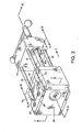
- Figure 3 is a perspective view of an in-balance condition of a lock collar, a friction block, and a coupling box when the unit being positioned is held in a substantially weightless condition by the counterbalances.
- Figure 4 is a perspective view of an out-of-balance condition of the lock block, the panel block, and the coupling box when the unit being positioned is In an unbalanced condition.
- Figure 5A is a vertical section taken along line 5A-5A of Figure 3.
- Figure 5B is a vertical section taken along line 5B-5B of Figure 4.
- Figure 6A is a vertical section taken along
line 6A-6A of Figure 3. - Figure 6B is a vertical section taken along
line 6B-6B of Figure 4. - Figure 7A is a side view of the coupling box.
- Figure 7B is a vertical section taken along
line 7B - 7B of Figure 3. - Figure 7C is a vertical section taken along line 7C - 7C of Figure 4.
- Figure 8 is a first perspective view of a second embodiment of the invention showing the load carrying unit.
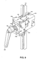
- Figure 9 is a second perspective view of a second embodiment of the invention without the load carrying unit.
- Figure 10 is a top section view of Figure 8.
- Referring again to the safety lock disclosed in U.S. Patent No. 4,715,574, upon a preselected movement of the arm caused by a loss of counterbalance to the arm, the safety lock prevented rotation of the handle that released the lock. It was known to the inventors, however, that certain users of the safety lock forgot its purpose. Thus, when those users couldn't turn the handle by hand, they would force the handle, thus breaking internal teeth which were preventing the lock from being released.
- Accordingly, the present invention relates to a new and improved materials handling system. Furthermore, a safety mechanism is disclosed for a materials handling system for a load such as a test head (or other electronic testing device). Thus, if a balanced condition is lost while the system is locked, the system cannot be unlocked and the load cannot be moved.
- Referring to Figures 1 and 2, a first embodiment of a materials handling system, constructed in accordance with the present invention, includes a support, identified generally by
reference numeral 10, which includes avertical support shaft 12.Support 10 may also include acolumn 14, in the form of an H-shaped beam (not shown), which extends upward from a base plate (not shown). Additional details aboutsupport 10, the H-shaped beam, and the base plate can be obtained by reference to U.S. Patent No. 4,527,942 and U.S. Patent No. 4,715,574. Load carrying unit 16 is adapted to receive a load which is to be positioned at a desired height alongshaft 12. Load carrying unit 16 includes an I-beam (not shown) which is mounted for movement alongshaft 12 by means of a pair of bearing blocks (not shown). Additional details about load carrying unit 16 and the manner in which the load carrying unit receives a load for positioning alongshaft 12 can be obtained by reference to U.S. Patent No. 4,527,942 and U.S. Patent No. 4,715,574. - The materials handling system illustrated in Figures 1 and 2 further includes counterbalancing means coupled to load carrying unit 16 for placing the load carrying unit and the load in substantially weightless condition. Only
cable 21 of the counterbalancing means is shown in Figure 1. - A
lock collar 24 having a bore 25, through whichshaft 12 extends, is movable along theshaft 12. A locking member system withinlock collar 24 having two locking members (e.g. wedges) 26 and 28 project through the wall of the bore 25 inlock collar 24 and engageshaft 12 to lock thelock collar 24 against vertical movement alongshaft 12. This is accomplished by arotatable handle 30 coupled towedges Wedge 26 has a threadedbore 26a.Wedge 28 has a bore 28a that is not threaded.Wedges shaft 12. -
Lock collar 24 has a bore 24a which receiveswedges inner lock shaft 30a of ahandle 30. A threadedend 30f ofinner lock shaft 30a engages the threadedbore 26a inwedge 26.Wedge 28 is mounted oninner lock shaft 30a by means of aneedle bearing 32 and rotates freely about the inner lock shaft. The interplay between the threads oninner lock shaft 30a and the threaded bore during rotation ofinner lock shaft 30a actuates movement ofwedge 26. Clockwise rotation ofInner lock shaft 30a moveswedge 26 towardwedge 28. Whenwedges lock collar 24 toshaft 12. Rotatinginner lock shaft 30a counter clockwise moveswedge 26 away fromwedge 28. Whenwedge 26 is a sufficient distance fromwedge 28,lock collar 24 is no longer locked toshaft 12 allowing the lock collar to move vertically along the shaft. The end ofinner lock shaft 30a away fromthreads 30f has acoupling face 35a with jaw-teeth thereon. - A second part of
handle 30 is anouter lock shaft 30b. Oneend 30c ofouter lock shaft 30b has ahandle 40 which may be used to turnouter lock shaft 30b. The other end ofouter lock shaft 30b has acoupling face 35b with jaw teeth thereon. When jaw-tooth couplings handle 30 in one direction causeswedges shaft 12 and to fix the position oflock collar 24 onshaft 12. Otherwise, rotation ofhandle 30 in an opposite direction causeswedges shaft 12, thereby permittinglock collar 24 to be moved along the shaft. - When
inner lock shaft 30a andouter lock shaft 30b are aligned, the jaw teeth on coupling faces 35a and 35b may be engaged with each other. When the two jaw-tooth couplings are engaged, rotation ofouter lock shaft 30b causesinner lock shaft 30a to similarly rotate, which actuateswedge 26. - A
coupling structure 18 is connected to load carrying unit 16 and to friction block 34 by means of four bolts which extend from the coupling structure into thefriction block 34. Some of the bolts are shown in Figures 1-4.Coupling structure 18 has afirst face 18a and asecond face 18b. Anelongated bore 18c is located withinface 18a. There are twoconcentric bores face 18b. The diameter ofbore 18d is smaller than the diameter ofbore 18e. The depth ofbore 18e withincoupling structure 18 is less than the depth ofbore 18d.Bore 18d extends from the inside ofbore 18e until it meets bore 18c. - Jaw-
tooth couplings bore 18c ofcoupling structure 18.Bore 18c is large enough to hold jaw-tooth couplings Bore 18d is large enough to allow entry and rotation ofouter lock shaft 30b. -
Outer lock shaft 30b is a single piece that is machined into twoseparate sections section 30d being less than the diameter ofsection 30c. The junction ofsections compression spring 31 is located between the annular wall ofbore 18e withincoupling structure 18 and the lip formed by the junction ofsections Compression spring 31 applies a horizontal force againstouter handle section 30b to force it away fromface 18b, thereby tending to force jaw-tooth couplings inner lock shaft 30a andouter lock shaft 30b are aligned, jaw-tooth couplings compression spring 31 onouter lock shaft 30b. Jaw-tooth couplings outer lock shaft 30b in towardinner lock shaft 30a against the compression force ofspring 31. - In normal operation, load carrying unit 16 and the load (not shown) carried by the load carrying unit are counterbalanced to permit easy movement along
shaft 12 to position the load at a desired height. Next,lock collar 24 is locked in place alongshaft 12 by turninghandle 30 clockwise to causewedges wedges shaft 12. - If the balanced system becomes unbalanced while
lock collar 24 is locked toshaft 12 and this fact is unknown to the individual unlocking the lock collar from the shaft, an undesirable condition exists. A loss in the counterweights causes load carrying unit 16 and its load to move downward suddenly, while removal of the load will cause unit 16 to move upward suddenly. - Accordingly, the present invention includes a prevention mechanism that prevents jaw-
tooth couplings collar 24. The prevention mechanism includesfriction block 34 and its relationship tocoupling structure 18 andouter lock shaft 30b.Friction block 34 bears against and is secured to the I-beam and to lockcollar 24. As shown in Figure 5A,friction block 34 has abore 38 through whichinner lock shaft 30a may extend. A series ofholes 36 permit bolts such asbolts friction block 34 tocoupling structure 18. - The coupling of
friction block 34 to lockcollar 24 andouter lock shaft 30b reacts to the relationship between the weight and counterweight to cause either an alignment or a non-alignment ofinner lock shaft 30a andouter lock shaft 30b. The two shafts are aligned when the load is substantially weightless. If the load loses too much of its weightless characteristic, a preselected amount of relative movement between the load and the counterweight causes the inner lock shaft and the outer lock shaft to become misaligned, thereby preventing the outer shaft from rotating theinner lock shaft 30a and preventing movement ofwedge 26. - Referring to Figure 5A, the determination of such relative movement is accomplished, in part, by a plurality of socket head screws 44 having the undersides of their heads slip fit against the bottoms of a corresponding number of
elongated counterbores 46 provided in that face offriction block 34. Thescrews 44 extend throughbores 47 infriction block 34 intolock collar 24. The opposite face offriction block 34 bears againstlock collar 24. -
Bores 47 are elongated and sized relative to the diameters ofscrews 44 to permit a preselected vertical movement of load carrying unit 16 relative to lockcollar 24 while the lock collar is locked toshaft 12. The clearance for thescrews 44 to move vertically within bores 47 is shown in Figure 5A. Thefriction block 34 may slide relative to lockcollar 24 for vertical movement of load carrying unit 16 while the lock collar is locked toshaft 12. - Figures 3, 4, 5A, 5B, 6A, and 6B show how the apparatus may be used to detect relative movement between load carrying unit 16 and
lock collar 24 when there is an imbalance from the substantially weightless condition. Four leaf springs are all attached to the lock collar. Leaf springs 50 and 52 are attached to the top of thelock collar 24 viaplate 66 andfasteners lock collar 24 andfriction block 34 are at substantially the same level,leaf springs friction block 34 during the substantially weightless condition of load carrying unit 16. Similarly,leaf springs friction block 34 during the substantially weightless condition of the load carrying unit. Until the resistance ofleaf springs friction block 34 is exceeded or until the resistance ofleaf springs friction block 34 is exceeded, thefriction block 34 remains in place and the teeth of the jaw-tooth couplings may be engaged. - Referring to Figure 7A,
face 18a ofcoupling structure 18 is shown.Holes 37 are adapted to receive bolts such asbolts lock collar 24, andfriction block 34. Figure 3 also shows the teeth of jaw-tooth coupling 35b insidebore 18e. Figure 7B shows the side of jaw-tooth coupling 35a that is coupled toinner lock shaft 30a. Because the load carrying unit is substantially weightless, jaw-tooth coupling 35a is aligned with jaw-tooth coupling 35b, thereby preventing jaw-tooth coupling 35b from being seen in Figure 7A. - When the load carrying unit is substantially weightless, the relative positions of other parts of the apparatus are shown in Figures 3, 5A and 6A. As shown in Figure 3,
bolts inner lock shaft 30a. Since the inner and outer lock shafts are aligned,bolts outer lock shaft 30b. As shown in Figure 5A, screws 44 are centered within bores 47. As shown in Figure 6A,leaf springs lock collar 24 to and against the top offriction block 34. This orientation of the leaf springs with the lock collar and thefriction block 34 means that the friction block has not moved relative to the lock collar. Consequently, jaw-tooth couplings tooth couplings wedges shaft 12. - Figures 4, 5B, 6B and 7C show the orientation of the elements of the invention when the load carrying unit is not substantially weightless. Under that circumstance, when the resistance of
leaf springs friction block 34 is exceeded,friction block 34 moves upward forcingleaf springs coupling structure 18 is shown in Figures 7B and 7C. A comparison between Figures 5A and 5B shows that the relative positions ofscrews 44 and bores 46 has changed. In Figure 5A, screws 44 are in the center ofbores 47, the tops of the bolts inupper holes 36 are substantially level with the tops ofupper screws 44, and the bottoms of the bolts inlower holes 36 are below the bottoms of lower screws 44. In Figure 5B, bores 47 have moved upward along withfriction block 34 resulting inscrews 44 being located at the bottom ofbores 47. As a result, the tops of the bolts inupper holes 36 are no longer substantially level with the tops ofupper screws 44. Instead, the tops ofupper screws 44 are below the tops of the bolts inupper holes 36. Similarly, the bottoms of the bolts inlower holes 36 are now substantially level with the bottoms of lower screws 44. - The effect of the relative movement between
lock collar 24 andfriction block 34 is shown in Figures 6B and 7C. Referring to Figure 6B, whenfriction block 34 moves upward, it causes the four bolts, includingbolts bolt 21 shown in Figure 4, will also move upward.Inner lock shaft 30a does not move relative to lockcollar 24 becauseinner lock shaft 30a is coupled to wedge 28 and no part ofwedge 28 is insidefriction block 34. Therefore,inner lock shaft 30a remains stationary whenfriction block 34 moves. As shown in Figures 5B, 6B and 7A,bolts coupling structure 18 viaholes 37. As shown in Figure 6B, upward movement ofbolts causes coupling structure 18 to also move upward. Becauseouter lock shaft 30b is located tightly within a small bore incoupling structure 18,outer lock shaft 30b is misaligned relative toinner lock shaft 30a thereby preventing engagement of jaw-tooth couplings handle 10 from openingwedges tooth couplings tooth coupling 35b is above, and not aligned or engaged with, jaw-tooth coupling 35a. - Figures 8-10 show a second exemplary embodiment of the invention. Referring to Figures 8 and 9, a second embodiment of a materials handling system, constructed in accordance with the present invention, includes a support identified generally by
reference numeral 110, which includes avertical support rail 112.Support 110 may also include acolumn 114 which extends from abase plate 115.Load carrying unit 116 is adapted to receive a load which is to be positioned at a desired height alongrail 112.Load carrying unit 116 is mounted for movement alongrail 112. - The materials handling system illustrated in Figures 8-10 further includes counterbalancing means coupled to load carrying
unit 116 for placing the load carrying unit and the load in substantially weightless condition. - A
lock collar 124 having anopening 125, through which rail 112 extends, is movable along therail 112. A caliper lock system withinlock collar 124 having twocalipers opening 125 inlock collar 124 and engagerail 112 to lock the lock collar against vertical movement along the shaft. This is accomplished by arotatable handle 130 coupled tocalipers Caliper 126 has a threadedhole 126a.Caliper 128 is not threaded. - A threaded
end 130f ofinner lock shaft 130a engages the threads oncaliper 126.Caliper 128 is also mounted oninner shaft 130a by means of a needle bearing (not shown) and rotates freely about the inner lock shaft. The interplay between the threads oninner lock shaft 130a and the threads oncaliper 126 during rotation ofinner lock shaft 130a actuates movement ofcaliper 126. Clockwise rotation ofinner lock shaft 130a movescaliper 126 towardcaliper 128. Whencalipers rail 112, they lock thelock collar 124 torail 112. Rotatinginner lock shaft 130a counter clockwise movescaliper 126 away fromcaliper 128. Whencaliper 126 is a sufficient distance fromcaliper 128,lock collar 124 is no longer locked to rail 112 allowing the lock collar to move vertically along the rail. The end ofinner lock shaft 130a away fromthreads 130f has acoupling face 135a with jaw-teeth thereon. - A
friction block 134 bears against and is secured to lockcollar 124. - A second part of
handle 130 is anouter lock shaft 130b. One end ofouter lock shaft 130b has ahandle 140 which may be used to turnouter lock shaft 130b. The diameter ofhandle 140 is greater than the diameter ofouter lock shaft 130b. The junction ofhandle 140 andouter lock shaft 130b forms a lip. Acompression spring 131 is located betweenface 134a offriction block 134 and the lip formed by the junction ofhandle 140 andouter lock shaft 130b. The other end ofouter lock shaft 130b has acoupling face 135b with jaw teeth thereon.Outer lock shaft 130b andcoupling face 135b are located within a bore infriction block 134. When jaw-tooth couplings handle 130 in one direction causescalipers rail 112 and to fix the position oflock collar 124 onrail 112. Otherwise, rotation ofhandle 130 in an opposite direction causescalipers rail 112, thereby permittinglock collar 124 to be moved along the rail. - When
inner lock shaft 130a andouter lock shaft 130b are aligned, the jaw teeth on coupling faces 135a and 135b may be engaged with each other. When the two jaw-tooth couplings are engaged, rotation ofouter lock shaft 130b causesinner lock shaft 130a to similarly rotate, which actuatescaliper 126. - As described above, jaw-
tooth coupling 135a may be located withinlock collar 124 and jaw-tooth coupling 135b may be located withinfriction block 134.Compression spring 131 applies a horizontal force againsthandle 140 and, consequently, againstouter lock shaft 130b. This force pushesouter lock shaft 130b away frominner lock shaft 130a, thereby tending to push jaw-tooth couplings inner lock shaft 130a andouter lock shaft 130b are aligned, jaw-tooth couplings compression spring 131 onouter lock shaft 130b. Jaw-tooth couplings outer lock shaft 130b in towardinner lock shaft 130a against the compression force ofspring 131. - The second exemplary embodiment of the invention prevents jaw-
tooth couplings collar 124. The prevention mechanism includesfriction block 134 and its relationship to lockcollar 124. The second embodiment shown in Figures 8 and 9 have the same mechanisms as shown in Figure 5A for sensing misalignment between the load and the counterweight. These mechanisms are shown generally asbores 147 in Figures 8 and 9. - Leaf springs 150 and 152 are attached to the top of the
friction block 134 viaclamp 166. Two additional leaf springs (not shown) are similarly attached to the bottom offriction block 134. When the tops oflock collar 124 and friction block 134 are at substantially the same level,leaf springs friction block 134 and bear against the top oflock collar 124 during the substantially weightless condition ofload carrying unit 116. Similarly, the leaf springs (not shown) clamped to the bottom offriction block 134 extend from the bottom of the lock collar and bear against the bottom of thefriction block 134 during the substantially weightless condition of the load carrying unit. Until the resistance ofleaf springs friction block 134 is exceeded or until the resistance of the leaf springs clamped to the bottom of thefriction block 134 is exceeded, thefriction block 134 remains in place and the teeth of the jaw-tooth couplings may be engaged. - When the load carrying unit is substantially weightless,
inner lock shaft 130a is aligned withouter lock shaft 130b and jaw-tooth couplings tooth couplings calipers rail 112. - When the load carrying unit is not substantially weightless, and when the resistance of
leaf springs friction block 134 is exceeded, friction block 134 moves upward forcingleaf springs lock collar 124 andfriction block 134,inner lock shaft 130a remains stationary because it is located withinlock collar 124. Becauseouter lock shaft 130b is located tightly within a small bore infriction block 134,outer lock shaft 130b is misaligned relative toinner lock shaft 130a. The misalignment of the two lock shafts prevents engagement of jaw-tooth couplings caliper 126.
Claims (15)
- A safety lock comprising:a locking member which engages a support (10; 110);a handle (30), having an inner lock shaft (30a; 130a) for actuating said locking member and an outer lock shaft (30b; 130b), characterized in thatsaid inner lock shaft (30a; 130a) having a first coupling face (35a; 135a) at one end thereof; andsaid outer lock shaft (30b; 130b) having a second coupling face (35b; 135b) which engages said first coupling face (35a; 135a) when said inner lock shaft (30a; 130a) and said outer lock shaft (30b; 130b) are in respective engagement positions relative to each other; wherein the safety lock further comprisesa coupling structure (18) which moves to prevent engagement of said first coupling face (35a; 135a) with said second coupling face (35b; 135b).
- The safety lock according to claim 1, wherein said locking member is a wedge (26; 28) or a caliper (126; 128).
- The safety lock according to claim 1, further comprising a lock collar (24; 124) in which said locking member is situated, wherein actuation of said locking member prevents movement of said lock collar (24; 124) along said support (10; 110).
- The safety lock according to claim 3, further comprising a coupling box secured to said lock collar (24; 124) and moveable thereto, said inner lock shaft (30a; 130a) held by said lock collar (24; 124), said outer lock shaft (30b; 130b) held by said coupling box.
- The safety lock according to claim 3, wherein a counterbalanced load is coupled to said lock collar (24; 124).
- The safety lock according to claim 4, wherein flexible members secure said coupling box to said lock collar (24; 124).
- The safety lock according to claim 5, wherein said coupling box is secured to said lock collar (24; 124) via a friction block (34) which is rigidly attached to said coupling box, said load situated between said friction block (34) and said coupling box.
- The safety lock according to claim 1, further comprising a spring loaded handle coupled to said outer lock shaft (30b; 130b), said spring urging said first coupling face (35a; 135a) and said second coupling face (35b; 135b) apart.
- The safety lock according to claim 4, wherein said outer lock shaft (30b; 130b) is linearly stationary relative to said coupling box.
- The safety lock according to claim 5, wherein said load is a test head.
- A method of locking a load, said method comprising the step of:operating a handle (30) having an inner lock shaft (30a; 130a) and an outer lock shaft (30b; 130b), characterized in that said method further comprises the steps of:operating the outer lock shaft (30b; 130b) and thus causing the inner lock shaft (30a; 130a) to cause a locking member to engage a support (10; 110) when respective first and second coupling faces (35a; 135a; 35b; 135b) of said inner lock shaft (30a; 130a) and said outer lock shaft (30b; 130b) are positioned for engagement with each other; andoperating said outer lock shaft (30b; 130b) without causing said inner lock shaft (30a; 130a) to disengage said locking member from said support (10; 110) when said respective first and second coupling faces (35a; 135a; 35b; 135b) of said inner lock shaft (30a; 130a) and said outer lock shaft (30b; 130b) are positioned away from engagement with each other.
- The method of locking a load according to claim 11, wherein said locking member is a wedge (26; 28) or a caliper (126; 128) which engages said support (10; 110).
- The method of locking a load according to claim 11, wherein said locking member is situated in a lock collar (24; 124), a coupling box is secured to said lock collar (24; 124) and is movable thereto, said inner lock shaft (30a; 130a) is held by said lock collar (24; 124), and said outer lock shaft (30b; 130b) is held by said coupling box, said inner lock shaft (30a; 130a) and said outer lock shaft (30b; 130b) shaft are away from engagement with each other when said coupling box moves relative to said lock collar (24; 124).
- The method of locking a load according to claim 13, wherein said coupling box moves relative to said lock collar (24; 124) when counterbalancing of a load coupled to said coupling box changes.
- The method of locking a load according to claim 11, wherein a spring urges said first coupling face (35a; 135a) and said second coupling face (35b; 135b) apart.
Applications Claiming Priority (3)
| Application Number | Priority Date | Filing Date | Title |
|---|---|---|---|
| US44838203P | 2003-02-18 | 2003-02-18 | |
| US448382P | 2003-02-18 | ||
| PCT/US2004/004936 WO2004073920A1 (en) | 2003-02-18 | 2004-02-18 | Safety mechanism for materials handling system |
Publications (2)
| Publication Number | Publication Date |
|---|---|
| EP1597016A1 EP1597016A1 (en) | 2005-11-23 |
| EP1597016B1 true EP1597016B1 (en) | 2007-04-04 |
Family
ID=32908581
Family Applications (1)
| Application Number | Title | Priority Date | Filing Date |
|---|---|---|---|
| EP04712424A Expired - Lifetime EP1597016B1 (en) | 2003-02-18 | 2004-02-18 | Safety mechanism for materials handling system |
Country Status (8)
| Country | Link |
|---|---|
| US (1) | US7845607B2 (en) |
| EP (1) | EP1597016B1 (en) |
| JP (1) | JP2006523299A (en) |
| KR (1) | KR20050102648A (en) |
| CN (1) | CN1750903A (en) |
| AT (1) | ATE358549T1 (en) |
| DE (1) | DE602004005676T2 (en) |
| WO (1) | WO2004073920A1 (en) |
Families Citing this family (6)
| Publication number | Priority date | Publication date | Assignee | Title |
|---|---|---|---|---|
| DE102006062295B4 (en) * | 2005-06-24 | 2008-09-04 | Zimmer, Günther | Clamping device with at least one encompassing clamping element |
| WO2012097779A1 (en) * | 2010-12-30 | 2012-07-26 | Gartner Steel And Glass Gmbh | Holding device for flat elements |
| US9585470B2 (en) * | 2014-02-19 | 2017-03-07 | JORO Manufacturing Company Ltd. | Position-adjustable support assembly |
| JP6298694B2 (en) * | 2014-04-11 | 2018-03-20 | キヤノンファインテックニスカ株式会社 | Operation handle mechanism and load support mechanism |
| US9718177B1 (en) * | 2014-06-26 | 2017-08-01 | Charles Bell | Gasket removal and insertion tools for refrigeration hoses |
| US10179392B2 (en) * | 2015-01-23 | 2019-01-15 | Chris Taylor | Multi_station fixture vise |
Family Cites Families (9)
| Publication number | Priority date | Publication date | Assignee | Title |
|---|---|---|---|---|
| US214907A (en) * | 1879-04-29 | Improvement in bench-vises | ||
| US2603325A (en) * | 1952-07-15 | -socket wrench head | ||
| US2261055A (en) * | 1940-07-30 | 1941-10-28 | Ira J Dulaney | Watch movement holder |
| US4448406A (en) * | 1982-03-31 | 1984-05-15 | The United States Of America As Represented By The Administrator Of The National Aeronautics And Space Administration | Workpiece positioning vise |
| US4715574A (en) | 1985-11-12 | 1987-12-29 | Intest Corporation | Safety lock for materials handling system |
| DE3831375A1 (en) * | 1988-09-15 | 1990-03-22 | Bessey & Sohn | CLAMPING DEVICE |
| US5092572A (en) * | 1990-10-05 | 1992-03-03 | Anstat, Inc. | Allograft vise |
| US5501440A (en) * | 1994-07-08 | 1996-03-26 | Blise; Bernard G. | Vise |
| GB2364348B (en) * | 2000-06-15 | 2004-11-24 | Austral Lock Ind Pty Ltd | Padlocks |
-
2004
- 2004-02-18 CN CNA2004800044216A patent/CN1750903A/en active Pending
- 2004-02-18 JP JP2006503715A patent/JP2006523299A/en active Pending
- 2004-02-18 US US10/545,537 patent/US7845607B2/en not_active Expired - Fee Related
- 2004-02-18 WO PCT/US2004/004936 patent/WO2004073920A1/en not_active Ceased
- 2004-02-18 DE DE602004005676T patent/DE602004005676T2/en not_active Expired - Lifetime
- 2004-02-18 EP EP04712424A patent/EP1597016B1/en not_active Expired - Lifetime
- 2004-02-18 AT AT04712424T patent/ATE358549T1/en not_active IP Right Cessation
- 2004-02-18 KR KR1020057015127A patent/KR20050102648A/en not_active Withdrawn
Also Published As
| Publication number | Publication date |
|---|---|
| WO2004073920A1 (en) | 2004-09-02 |
| DE602004005676D1 (en) | 2007-05-16 |
| KR20050102648A (en) | 2005-10-26 |
| US7845607B2 (en) | 2010-12-07 |
| US20060207300A1 (en) | 2006-09-21 |
| EP1597016A1 (en) | 2005-11-23 |
| DE602004005676T2 (en) | 2007-08-02 |
| CN1750903A (en) | 2006-03-22 |
| ATE358549T1 (en) | 2007-04-15 |
| JP2006523299A (en) | 2006-10-12 |
Similar Documents
| Publication | Publication Date | Title |
|---|---|---|
| US6911816B2 (en) | Safety lock system for test head mount | |
| US7554321B2 (en) | Counter balanced vertical docking motion in a driven vertical axis test head manipulator | |
| US7235964B2 (en) | Test head positioning system and method | |
| KR100240476B1 (en) | Test head manipulator | |
| EP0811167B1 (en) | Manipulator for automatic test equipment test head | |
| US5506512A (en) | Transfer apparatus having an elevator and prober using the same | |
| US9134387B1 (en) | Test head positioner system | |
| US6448797B1 (en) | Method and apparatus automated docking of a test head to a device handler | |
| CN101788643A (en) | Manipulator for a test head with active compliance | |
| US7845607B2 (en) | Safety mechanism for materials handling system | |
| KR20190007640A (en) | Test equipment for bolts and nuts | |
| NO801246L (en) | DEVICE FOR AA SAFETY A RUBBING ELEMENT E.L. AGAINST AXIAL ROTATION, AND PROCEDURE FOR TURNING MEASUREMENT | |
| US4715574A (en) | Safety lock for materials handling system | |
| US20220219269A1 (en) | Tool assembly for tensioning tower bolts of a wind turbine tower | |
| US20100045323A1 (en) | Test head positioning system and method | |
| EP1145018B1 (en) | Test head manipulator | |
| CN100582786C (en) | Manipulator for a test head with active compliance | |
| US5641260A (en) | Shaft coupling device and locking mechanism | |
| JPH07147306A (en) | Device under test | |
| KR102769034B1 (en) | Leveling control system for acceleration tester | |
| HK1086222A (en) | Safety mechanism for materials handling system | |
| US20030230155A1 (en) | Manipulator apparatus with low-cost compliance | |
| JP4969406B2 (en) | Slide vertical adjustment mechanism | |
| EP1712923B1 (en) | Apparatus and method for balancing and for providing a compliant range to a test head | |
| JP7759084B2 (en) | Length measuring device |
Legal Events
| Date | Code | Title | Description |
|---|---|---|---|
| PUAI | Public reference made under article 153(3) epc to a published international application that has entered the european phase |
Free format text: ORIGINAL CODE: 0009012 |
|
| 17P | Request for examination filed |
Effective date: 20050803 |
|
| AK | Designated contracting states |
Kind code of ref document: A1 Designated state(s): AT BE BG CH CY CZ DE DK EE ES FI FR GB GR HU IE IT LI LU MC NL PT RO SE SI SK TR |
|
| AX | Request for extension of the european patent |
Extension state: AL LT LV MK |
|
| RAP1 | Party data changed (applicant data changed or rights of an application transferred) |
Owner name: INTEST CORPORATION |
|
| DAX | Request for extension of the european patent (deleted) | ||
| GRAP | Despatch of communication of intention to grant a patent |
Free format text: ORIGINAL CODE: EPIDOSNIGR1 |
|
| GRAS | Grant fee paid |
Free format text: ORIGINAL CODE: EPIDOSNIGR3 |
|
| GRAA | (expected) grant |
Free format text: ORIGINAL CODE: 0009210 |
|
| AK | Designated contracting states |
Kind code of ref document: B1 Designated state(s): AT BE BG CH CY CZ DE DK EE ES FI FR GB GR HU IE IT LI LU MC NL PT RO SE SI SK TR |
|
| PG25 | Lapsed in a contracting state [announced via postgrant information from national office to epo] |
Ref country code: FI Free format text: LAPSE BECAUSE OF FAILURE TO SUBMIT A TRANSLATION OF THE DESCRIPTION OR TO PAY THE FEE WITHIN THE PRESCRIBED TIME-LIMIT Effective date: 20070404 Ref country code: CH Free format text: LAPSE BECAUSE OF FAILURE TO SUBMIT A TRANSLATION OF THE DESCRIPTION OR TO PAY THE FEE WITHIN THE PRESCRIBED TIME-LIMIT Effective date: 20070404 Ref country code: LI Free format text: LAPSE BECAUSE OF FAILURE TO SUBMIT A TRANSLATION OF THE DESCRIPTION OR TO PAY THE FEE WITHIN THE PRESCRIBED TIME-LIMIT Effective date: 20070404 Ref country code: SI Free format text: LAPSE BECAUSE OF FAILURE TO SUBMIT A TRANSLATION OF THE DESCRIPTION OR TO PAY THE FEE WITHIN THE PRESCRIBED TIME-LIMIT Effective date: 20070404 |
|
| REG | Reference to a national code |
Ref country code: GB Ref legal event code: FG4D |
|
| REG | Reference to a national code |
Ref country code: CH Ref legal event code: EP |
|
| REF | Corresponds to: |
Ref document number: 602004005676 Country of ref document: DE Date of ref document: 20070516 Kind code of ref document: P |
|
| REG | Reference to a national code |
Ref country code: IE Ref legal event code: FG4D |
|
| PG25 | Lapsed in a contracting state [announced via postgrant information from national office to epo] |
Ref country code: SE Free format text: LAPSE BECAUSE OF FAILURE TO SUBMIT A TRANSLATION OF THE DESCRIPTION OR TO PAY THE FEE WITHIN THE PRESCRIBED TIME-LIMIT Effective date: 20070704 |
|
| PG25 | Lapsed in a contracting state [announced via postgrant information from national office to epo] |
Ref country code: ES Free format text: LAPSE BECAUSE OF FAILURE TO SUBMIT A TRANSLATION OF THE DESCRIPTION OR TO PAY THE FEE WITHIN THE PRESCRIBED TIME-LIMIT Effective date: 20070715 |
|
| PG25 | Lapsed in a contracting state [announced via postgrant information from national office to epo] |
Ref country code: PT Free format text: LAPSE BECAUSE OF FAILURE TO SUBMIT A TRANSLATION OF THE DESCRIPTION OR TO PAY THE FEE WITHIN THE PRESCRIBED TIME-LIMIT Effective date: 20070904 |
|
| NLV1 | Nl: lapsed or annulled due to failure to fulfill the requirements of art. 29p and 29m of the patents act | ||
| REG | Reference to a national code |
Ref country code: CH Ref legal event code: PL |
|
| PG25 | Lapsed in a contracting state [announced via postgrant information from national office to epo] |
Ref country code: AT Free format text: LAPSE BECAUSE OF FAILURE TO SUBMIT A TRANSLATION OF THE DESCRIPTION OR TO PAY THE FEE WITHIN THE PRESCRIBED TIME-LIMIT Effective date: 20070404 |
|
| EN | Fr: translation not filed | ||
| PG25 | Lapsed in a contracting state [announced via postgrant information from national office to epo] |
Ref country code: BE Free format text: LAPSE BECAUSE OF FAILURE TO SUBMIT A TRANSLATION OF THE DESCRIPTION OR TO PAY THE FEE WITHIN THE PRESCRIBED TIME-LIMIT Effective date: 20070404 |
|
| PG25 | Lapsed in a contracting state [announced via postgrant information from national office to epo] |
Ref country code: DK Free format text: LAPSE BECAUSE OF FAILURE TO SUBMIT A TRANSLATION OF THE DESCRIPTION OR TO PAY THE FEE WITHIN THE PRESCRIBED TIME-LIMIT Effective date: 20070404 Ref country code: CZ Free format text: LAPSE BECAUSE OF FAILURE TO SUBMIT A TRANSLATION OF THE DESCRIPTION OR TO PAY THE FEE WITHIN THE PRESCRIBED TIME-LIMIT Effective date: 20070404 Ref country code: NL Free format text: LAPSE BECAUSE OF FAILURE TO SUBMIT A TRANSLATION OF THE DESCRIPTION OR TO PAY THE FEE WITHIN THE PRESCRIBED TIME-LIMIT Effective date: 20070404 Ref country code: BG Free format text: LAPSE BECAUSE OF FAILURE TO SUBMIT A TRANSLATION OF THE DESCRIPTION OR TO PAY THE FEE WITHIN THE PRESCRIBED TIME-LIMIT Effective date: 20070704 |
|
| PLBE | No opposition filed within time limit |
Free format text: ORIGINAL CODE: 0009261 |
|
| STAA | Information on the status of an ep patent application or granted ep patent |
Free format text: STATUS: NO OPPOSITION FILED WITHIN TIME LIMIT |
|
| PG25 | Lapsed in a contracting state [announced via postgrant information from national office to epo] |
Ref country code: SK Free format text: LAPSE BECAUSE OF FAILURE TO SUBMIT A TRANSLATION OF THE DESCRIPTION OR TO PAY THE FEE WITHIN THE PRESCRIBED TIME-LIMIT Effective date: 20070404 |
|
| 26N | No opposition filed |
Effective date: 20080107 |
|
| PG25 | Lapsed in a contracting state [announced via postgrant information from national office to epo] |
Ref country code: GR Free format text: LAPSE BECAUSE OF FAILURE TO SUBMIT A TRANSLATION OF THE DESCRIPTION OR TO PAY THE FEE WITHIN THE PRESCRIBED TIME-LIMIT Effective date: 20070705 Ref country code: IT Free format text: LAPSE BECAUSE OF FAILURE TO SUBMIT A TRANSLATION OF THE DESCRIPTION OR TO PAY THE FEE WITHIN THE PRESCRIBED TIME-LIMIT Effective date: 20070404 Ref country code: FR Free format text: LAPSE BECAUSE OF FAILURE TO SUBMIT A TRANSLATION OF THE DESCRIPTION OR TO PAY THE FEE WITHIN THE PRESCRIBED TIME-LIMIT Effective date: 20071130 |
|
| PG25 | Lapsed in a contracting state [announced via postgrant information from national office to epo] |
Ref country code: RO Free format text: LAPSE BECAUSE OF FAILURE TO SUBMIT A TRANSLATION OF THE DESCRIPTION OR TO PAY THE FEE WITHIN THE PRESCRIBED TIME-LIMIT Effective date: 20070404 |
|
| GBPC | Gb: european patent ceased through non-payment of renewal fee |
Effective date: 20080218 |
|
| PG25 | Lapsed in a contracting state [announced via postgrant information from national office to epo] |
Ref country code: MC Free format text: LAPSE BECAUSE OF NON-PAYMENT OF DUE FEES Effective date: 20080228 |
|
| PG25 | Lapsed in a contracting state [announced via postgrant information from national office to epo] |
Ref country code: FR Free format text: LAPSE BECAUSE OF FAILURE TO SUBMIT A TRANSLATION OF THE DESCRIPTION OR TO PAY THE FEE WITHIN THE PRESCRIBED TIME-LIMIT Effective date: 20070404 |
|
| PG25 | Lapsed in a contracting state [announced via postgrant information from national office to epo] |
Ref country code: EE Free format text: LAPSE BECAUSE OF FAILURE TO SUBMIT A TRANSLATION OF THE DESCRIPTION OR TO PAY THE FEE WITHIN THE PRESCRIBED TIME-LIMIT Effective date: 20070404 Ref country code: IE Free format text: LAPSE BECAUSE OF NON-PAYMENT OF DUE FEES Effective date: 20080218 |
|
| PG25 | Lapsed in a contracting state [announced via postgrant information from national office to epo] |
Ref country code: GB Free format text: LAPSE BECAUSE OF NON-PAYMENT OF DUE FEES Effective date: 20080218 |
|
| PG25 | Lapsed in a contracting state [announced via postgrant information from national office to epo] |
Ref country code: CY Free format text: LAPSE BECAUSE OF FAILURE TO SUBMIT A TRANSLATION OF THE DESCRIPTION OR TO PAY THE FEE WITHIN THE PRESCRIBED TIME-LIMIT Effective date: 20070404 |
|
| PG25 | Lapsed in a contracting state [announced via postgrant information from national office to epo] |
Ref country code: HU Free format text: LAPSE BECAUSE OF FAILURE TO SUBMIT A TRANSLATION OF THE DESCRIPTION OR TO PAY THE FEE WITHIN THE PRESCRIBED TIME-LIMIT Effective date: 20071005 Ref country code: LU Free format text: LAPSE BECAUSE OF NON-PAYMENT OF DUE FEES Effective date: 20080218 |
|
| PG25 | Lapsed in a contracting state [announced via postgrant information from national office to epo] |
Ref country code: TR Free format text: LAPSE BECAUSE OF FAILURE TO SUBMIT A TRANSLATION OF THE DESCRIPTION OR TO PAY THE FEE WITHIN THE PRESCRIBED TIME-LIMIT Effective date: 20070404 |
|
| PGFP | Annual fee paid to national office [announced via postgrant information from national office to epo] |
Ref country code: DE Payment date: 20120229 Year of fee payment: 9 |
|
| REG | Reference to a national code |
Ref country code: DE Ref legal event code: R119 Ref document number: 602004005676 Country of ref document: DE Effective date: 20130903 |
|
| PG25 | Lapsed in a contracting state [announced via postgrant information from national office to epo] |
Ref country code: DE Free format text: LAPSE BECAUSE OF NON-PAYMENT OF DUE FEES Effective date: 20130903 |