EP1597010B1 - Precision cemented carbide threading tap - Google Patents
Precision cemented carbide threading tap Download PDFInfo
- Publication number
- EP1597010B1 EP1597010B1 EP04712301A EP04712301A EP1597010B1 EP 1597010 B1 EP1597010 B1 EP 1597010B1 EP 04712301 A EP04712301 A EP 04712301A EP 04712301 A EP04712301 A EP 04712301A EP 1597010 B1 EP1597010 B1 EP 1597010B1
- Authority
- EP
- European Patent Office
- Prior art keywords
- tap
- precision
- carbide
- outer layer
- cemented carbide
- Prior art date
- Legal status (The legal status is an assumption and is not a legal conclusion. Google has not performed a legal analysis and makes no representation as to the accuracy of the status listed.)
- Expired - Lifetime
Links
- 238000005520 cutting process Methods 0.000 claims abstract description 29
- 239000010410 layer Substances 0.000 claims description 18
- 229910052723 transition metal Inorganic materials 0.000 claims description 9
- OKTJSMMVPCPJKN-UHFFFAOYSA-N Carbon Chemical compound [C] OKTJSMMVPCPJKN-UHFFFAOYSA-N 0.000 claims description 7
- 229910052799 carbon Inorganic materials 0.000 claims description 7
- 229910052751 metal Inorganic materials 0.000 claims description 7
- 239000002184 metal Substances 0.000 claims description 7
- 150000003624 transition metals Chemical class 0.000 claims description 6
- CWQXQMHSOZUFJS-UHFFFAOYSA-N molybdenum disulfide Chemical compound S=[Mo]=S CWQXQMHSOZUFJS-UHFFFAOYSA-N 0.000 claims description 4
- 239000002356 single layer Substances 0.000 claims description 3
- -1 transition metal carbides Chemical class 0.000 claims description 3
- 229910052782 aluminium Inorganic materials 0.000 claims description 2
- XAGFODPZIPBFFR-UHFFFAOYSA-N aluminium Chemical compound [Al] XAGFODPZIPBFFR-UHFFFAOYSA-N 0.000 claims description 2
- 150000004767 nitrides Chemical class 0.000 claims description 2
- JMANVNJQNLATNU-UHFFFAOYSA-N oxalonitrile Chemical compound N#CC#N JMANVNJQNLATNU-UHFFFAOYSA-N 0.000 claims description 2
- 230000000737 periodic effect Effects 0.000 claims description 2
- 229910052710 silicon Inorganic materials 0.000 claims description 2
- 239000010703 silicon Substances 0.000 claims description 2
- 238000010079 rubber tapping Methods 0.000 abstract description 19
- 230000001360 synchronised effect Effects 0.000 abstract description 4
- 238000000034 method Methods 0.000 description 14
- 230000008569 process Effects 0.000 description 6
- 229910000831 Steel Inorganic materials 0.000 description 5
- 239000010959 steel Substances 0.000 description 5
- 238000005229 chemical vapour deposition Methods 0.000 description 4
- 239000000463 material Substances 0.000 description 4
- 239000000758 substrate Substances 0.000 description 4
- UONOETXJSWQNOL-UHFFFAOYSA-N tungsten carbide Chemical compound [W+]#[C-] UONOETXJSWQNOL-UHFFFAOYSA-N 0.000 description 4
- 238000005516 engineering process Methods 0.000 description 3
- 238000004519 manufacturing process Methods 0.000 description 3
- 229910001315 Tool steel Inorganic materials 0.000 description 2
- 150000001247 metal acetylides Chemical class 0.000 description 2
- 238000005240 physical vapour deposition Methods 0.000 description 2
- 229910000997 High-speed steel Inorganic materials 0.000 description 1
- ATJFFYVFTNAWJD-UHFFFAOYSA-N Tin Chemical compound [Sn] ATJFFYVFTNAWJD-UHFFFAOYSA-N 0.000 description 1
- 238000000429 assembly Methods 0.000 description 1
- 230000000712 assembly Effects 0.000 description 1
- 238000000576 coating method Methods 0.000 description 1
- 239000010941 cobalt Substances 0.000 description 1
- 229910017052 cobalt Inorganic materials 0.000 description 1
- GUTLYIVDDKVIGB-UHFFFAOYSA-N cobalt atom Chemical compound [Co] GUTLYIVDDKVIGB-UHFFFAOYSA-N 0.000 description 1
- 239000000470 constituent Substances 0.000 description 1
- 238000001816 cooling Methods 0.000 description 1
- 229910003460 diamond Inorganic materials 0.000 description 1
- 239000010432 diamond Substances 0.000 description 1
- 230000008020 evaporation Effects 0.000 description 1
- 238000001704 evaporation Methods 0.000 description 1
- 238000004050 hot filament vapor deposition Methods 0.000 description 1
- 230000006872 improvement Effects 0.000 description 1
- 239000012535 impurity Substances 0.000 description 1
- 238000007733 ion plating Methods 0.000 description 1
- 150000002500 ions Chemical class 0.000 description 1
- 238000003754 machining Methods 0.000 description 1
- 238000001755 magnetron sputter deposition Methods 0.000 description 1
- 230000007246 mechanism Effects 0.000 description 1
- 239000007769 metal material Substances 0.000 description 1
- UNASZPQZIFZUSI-UHFFFAOYSA-N methylidyneniobium Chemical compound [Nb]#C UNASZPQZIFZUSI-UHFFFAOYSA-N 0.000 description 1
- NFFIWVVINABMKP-UHFFFAOYSA-N methylidynetantalum Chemical compound [Ta]#C NFFIWVVINABMKP-UHFFFAOYSA-N 0.000 description 1
- 238000009877 rendering Methods 0.000 description 1
- 229910003468 tantalcarbide Inorganic materials 0.000 description 1
- MTPVUVINMAGMJL-UHFFFAOYSA-N trimethyl(1,1,2,2,2-pentafluoroethyl)silane Chemical compound C[Si](C)(C)C(F)(F)C(F)(F)F MTPVUVINMAGMJL-UHFFFAOYSA-N 0.000 description 1
- 238000007740 vapor deposition Methods 0.000 description 1
Images
Classifications
-
- B—PERFORMING OPERATIONS; TRANSPORTING
- B23—MACHINE TOOLS; METAL-WORKING NOT OTHERWISE PROVIDED FOR
- B23G—THREAD CUTTING; WORKING OF SCREWS, BOLT HEADS, OR NUTS, IN CONJUNCTION THEREWITH
- B23G5/00—Thread-cutting tools; Die-heads
- B23G5/02—Thread-cutting tools; Die-heads without means for adjustment
- B23G5/06—Taps
-
- B—PERFORMING OPERATIONS; TRANSPORTING
- B23—MACHINE TOOLS; METAL-WORKING NOT OTHERWISE PROVIDED FOR
- B23G—THREAD CUTTING; WORKING OF SCREWS, BOLT HEADS, OR NUTS, IN CONJUNCTION THEREWITH
- B23G2225/00—Materials of threading tools, workpieces or other structural elements
- B23G2225/28—Hard metal, i.e. cemented carbides
-
- Y—GENERAL TAGGING OF NEW TECHNOLOGICAL DEVELOPMENTS; GENERAL TAGGING OF CROSS-SECTIONAL TECHNOLOGIES SPANNING OVER SEVERAL SECTIONS OF THE IPC; TECHNICAL SUBJECTS COVERED BY FORMER USPC CROSS-REFERENCE ART COLLECTIONS [XRACs] AND DIGESTS
- Y10—TECHNICAL SUBJECTS COVERED BY FORMER USPC
- Y10T—TECHNICAL SUBJECTS COVERED BY FORMER US CLASSIFICATION
- Y10T408/00—Cutting by use of rotating axially moving tool
- Y10T408/78—Tool of specific diverse material
-
- Y—GENERAL TAGGING OF NEW TECHNOLOGICAL DEVELOPMENTS; GENERAL TAGGING OF CROSS-SECTIONAL TECHNOLOGIES SPANNING OVER SEVERAL SECTIONS OF THE IPC; TECHNICAL SUBJECTS COVERED BY FORMER USPC CROSS-REFERENCE ART COLLECTIONS [XRACs] AND DIGESTS
- Y10—TECHNICAL SUBJECTS COVERED BY FORMER USPC
- Y10T—TECHNICAL SUBJECTS COVERED BY FORMER US CLASSIFICATION
- Y10T408/00—Cutting by use of rotating axially moving tool
- Y10T408/89—Tool or Tool with support
- Y10T408/904—Tool or Tool with support with pitch-stabilizing ridge
- Y10T408/9048—Extending outwardly from tool-axis
Definitions
- This invention relates to cutting tools. More particularly, this invention relates to a precision cemented carbide tap for creating internal screw threads in machinable metallic and non-metallic materials.
- screw threads as fastener components dominates over all other means to join parts into assemblies.
- taps are the favored means to generate the internal screw thread.
- the dominant tapping method is by cutting and removing material from the walls of a hole to produce a helical V-shaped screw thread.
- internal screw threads can be created by displacing material to form an internal screw thread.
- the dimensional accuracy of the shape and size of the internal screw thread controls the precision and fit of the screw thread assembly. Additionally, the speed of tapping controls the cost to produce an internal screw thread.
- taps have been historically driven by drill presses or machine tools equipped with flexible tapping heads that allow the tap to rotate and feed at a rate that approximates the desired lead of the internal screw thread. Because the machine's feed is only approximate, the generated screw thread lead is controlled by the tap's lead, with the difference between the machine's feed and the tap lead accommodated by the flexible tapping head. Not only is accuracy affected by flexible tapping heads, but also the rate at which they can rotate is limited. Additionally, tapping heads allow the tap to run out radially during cutting, further limiting the accuracy of the screw thread as it is generated.
- the Japanese Patent Application JP 04 348813 A discloses a tap as per the preamble of claim 1 for small screws made of cemented carbide.
- the tap has a shank with a rounded portion and a portion with flats for securement to a holding device.
- An axial forward end includes a threaded portion and a chamfered edge.
- Taps have been recently been redesigned and constructed to allow use of shrink fit and hydraulic holders in the same manner as other rotating shank type tools, such as drills and end mills. Designed for use in these tool holders, taps are now available with fully cylindrical shanks without the aid of squares as with older designs, nor with other flats or other notches. However, taps are not currently manufactured with a cylindrical shank of sufficient accuracy (diameter and roundness) to allow the full use of shrink fit and hydraulic holders. Reference can be made to American National Standard, A.S.M.E. B94.9-1999 for design and tolerance of currently known taps.
- the tolerance of the shank diameter is + 0.0000, -0.0015 inch (38 micrometers).
- the requirement is the eccentricity must be no more than 0.0008 inch (20 micrometers) for the shank and major diameter, and 0.0015 inch (38 micrometers) for the chamfered cutting edges, respectively, when these features are measured to the centers on which the tap is held during manufacturing.
- the diameter of the shank must be to h6 of DIN standard 7160 which requires, for example, the shank of a 12 mm tap to have a diameter tolerance of +0, -11 micrometers (+0, - 0.0004 inch) of the nominal diameter and the roundness be 3 microns (0.00012 inch) or less.
- Runout is defined as the radial variation from a true circle that lies in a diametric plane and is concentric with the tool axis. In practice, runout is typically measured with a device such as a dial indicator, mounted at right angles to the axis of a cylinder, and expressed as total indicator variation (tiv). Eccentricity is defined as one-half the runout or total indicator variation. Because taps are held by the shank during use, the runout of the threaded cutting portions of the tap can be most effectively measured by precisely holding the tap by the shank and measuring the runout as the tap is rotated.
- Cemented tungsten carbide is favored as a material for manufacturing cutting tools over tool steels such as high-speed steel owing to properties such as higher hardness and high temperature stability including the ability to retain hardness at high temperatures.
- cutting tools manufactured from cemented carbide can be used a cutting speeds that are at least three times higher than tools manufactured from "high-speed" steel and the life of the tool is longer.
- cemented tungsten carbide has lower fracture toughness and strength than tool steel and this limits its use to machining operations where the cutting tool can be stiffly held.
- taps manufactured from cemented carbide only have very limited use, even with the aid of shrink fit and hydraulic holders. When carbide taps of current concentricity are used, cutting edges can chip or fracture easily rendering the tool useless. Additionally, the speed with which such taps can be used will be limited because the runout of the taps will increase as the rotational speed of the taps increases.
- a precision cemented carbide tap as defined in claim 1.
- the tap includes a fully cylindrical shank and whose threaded body and cutting chamfer is concentric to the shank within 10 microns, thereby improving the accuracy and speed by which internal screw threads are produced.
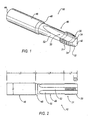
- Figure 1 is a perspective view of the a precision cemented carbide threading tap according to an embodiment of the invention.
- Figure 2 is a side view of the precision cemented carbide threading tap of Figure 1 .
- the tap 10 is manufactured from a cylindrical sintered tungsten carbide blank, frequently referred to as a substrate.
- the blank has a diameter that is sized larger than the finished dimensions of the tap 10 and is cut to length on surfaces 42 and 44.
- a typical material for the substrate is metal carbide(s) cemented with cobalt.
- the main carbide constituent is tungsten carbide, other carbides may be used such as tantalum carbide, titanium carbide and niobium carbide.
- small amount of transition metal carbides may be added to restrain grain growth, and the substrate may also contain small amount of inevitable impurities.
- the first step in processing the substrate is to grind the blank to precision cylindrical tolerances by methods such as cylindrical traverse grinding on centers or by centerless infeed grinding methods.
- a cylindrical shank 46 is ground to size at the axially rearward end of the tap 10 without squares, flats or other notches, and the major diameter of a threaded body portion 31 is formed at the axially forward end of the tap 10.
- the surface of the cylindrical shank 46 is ground to the diameter tolerances h6 stated in Deutsche Normen DIN 7160 and with roundness of 3 microns or less.
- an optional neck portion 49 may be created with a cylindrical surface 52, and a bevel 48 between the cylindrical shank 46 and the neck portion 49.
- an optional bevel 24 may be ground by cylindrical grinding.
- the shank diameter, D is approximately equal to the nominal thread diameter, but the shank diameter may be smaller than the nominal thread diameter for large diameter taps, and alternatively larger for small diameter taps.
- the blank is then held by the cylindrical shank 46 by precision hydraulic holders during grinding in order to insure that a threaded body portion 31 and a threaded cutting chamfer portion 30 are concentric to the cylindrical shank 46 within a runout of 10 microns.
- one or more flutes 50 are ground so as to provide cutting edges, in combination with the chamfer 30, and a means for evacuating chips that form when the tap is used.
- the flutes 50 are straight and generally oriented parallel to the axis of the tap 10. It should be realized that other flute orientations are possible.
- short flutes may be ground at a 5 to 20 degree angle to the longitudinal axis of the tap 10 at the entry section of the tap in order to force the chip ahead of the motion of the tap during use.
- the flutes 50 may be helical, the helical rotation selected according to whether it is desirable to pull chips out of the hole or push chips ahead of the motion of the tap during use.
- the threaded body portion 31 is ground to form V-shaped thread flank surfaces, along with minor and major diameters, on a helix.
- the shape of a threaded cutting chamfer portion 30 is formed by grinding.
- the V-shaped thread flank surfaces and major diameter replicate the internal screw thread that is generated during tapping.
- the threaded cutting chamfer portion 30 is tapered so as to allow entry in the hole to be tapped.
- the tap 10 is coated with a wear resistant layer (not shown) of metal nitrides, carbides or carbonitrides optionally, borides and/or oxides, wherein the metal is chosen from one or more of the following: aluminum, silicon and the transition metals from Groups IVa, Va, and VIa of the Periodic Chart.
- This layer is deposited as a single monolayer or in multiple, including alternating, layers.
- the wear resistant layer may be coated with a second outer friction reducing layer (not shown) comprised of molybdenum disulphide; molybdenum disulphide and transition metals carbon; carbon and transition metal carbides; carbon and a transition metal; carbon; and carbon nitride.
- the outer layer is deposited as a single monolayer or in multiple layers, including alternating layers.
- Both the wear resistant layer and the outer friction reducing layer may be applied by use of a vapor deposition technique such as one of the well known physical vapor deposition (PVD) techniques, for example, any high ion density process such as, ion plating, magnetron sputtering, arc evaporation, or the like, or a chemical vapor deposition (CVD) technique by use of a variety of CVD processes that would achieve a satisfactory CVD layer.
- PVD physical vapor deposition
- CVD chemical vapor deposition
- a hot filament CVD process may be used to apply diamond coatings.
- the precision cemented carbide threading tap 10 is represented as a side view in Figure 2 . Shown at the left in Figure 2 is the shank 46 having a diameter, D, and length LS. Shown at the right in Figure 2 is the threaded body portion 31 having a length, LT, and including the tapered cutting chamfer portion 30 having a length, LC.
- An optional characteristic of the tap 10 is that it may contain the neck portion 49 of reduced diameter over the length, LN. During tapping, the tap 10 enters the hole to be threaded by the tapered cutting chamfer portion 30.
- the threaded body portion 31 and the threaded cutting chamfer portion 30 are concentric to the cylindrical shank 46 within a runout of 10 microns, such that when the tap 10 is held by precision tap holders (not shown) during use, the threaded body portion 31 and the threaded cutting chamfer portion 30 of the tap 10 may be rotated by synchronous tapping machines (not shown) with combined runout that is so minimal that the runout does not affect the accuracy of the threaded hole nor the speed by which the tap 10 may be used.
- Tests were conducted to prove the cutting effectiveness of the precision cemented carbide threading tap 10.
- a M12 x 1.25 mm pitch precision cemented carbide threading tap was tested by tapping 33 HRC AISI 4340 steel at 91 m/min at (300 feet/minute) on a synchronous tapping machine.
- the precision tap tapped 1686 holes of acceptable gauging quality with little wear, whereas a TiN coated HSS tap manufactured to A.S.M.E. B94.9-1999 could only produce 158 holes of acceptable quality. Only at a reduced speed of 15 m/min (50 feet/minute) could the conventional tap produce a comparable number of threaded holes.
- the precision tap of the invention has numerous advantages over existing tap technology by improving the accuracy and speed by which internal screw threads can be produced.
- the precision tap of the invention with a cylindrical shank produced to an improved diameter tolerance allows the effective use of precision shrink fit and hydraulic holders on CNC machine tools with tapping spindles that synchronize the rotation and feed accurately to the tap's lead.
- the accuracy of internal screw threads is improved when the invented tap is used with these precision holders.
- a tap manufactured from cemented carbide taps with low small amounts of runout between the cutting body and the shank may be used with dramatically improved cutting speeds.
Landscapes
- Engineering & Computer Science (AREA)
- Mechanical Engineering (AREA)
- Milling Processes (AREA)
- Carbon And Carbon Compounds (AREA)
- Compositions Of Oxide Ceramics (AREA)
- Inorganic Fibers (AREA)
- Pens And Brushes (AREA)
- Cutting Tools, Boring Holders, And Turrets (AREA)
Abstract
Description
- This invention relates to cutting tools. More particularly, this invention relates to a precision cemented carbide tap for creating internal screw threads in machinable metallic and non-metallic materials.
- Mechanisms and machine components requiring screw threads have a long history in technology. Specifically, the application of screw threads as fastener components dominates over all other means to join parts into assemblies. Although there are many ways to generate screw threads both internal as well as external, experience has shown that taps are the favored means to generate the internal screw thread. There currently exist two tapping methods to generate internal screw threads. The dominant tapping method is by cutting and removing material from the walls of a hole to produce a helical V-shaped screw thread. Alternatively, internal screw threads can be created by displacing material to form an internal screw thread.
- The dimensional accuracy of the shape and size of the internal screw thread controls the precision and fit of the screw thread assembly. Additionally, the speed of tapping controls the cost to produce an internal screw thread. During the manufacturing of threaded holes, taps have been historically driven by drill presses or machine tools equipped with flexible tapping heads that allow the tap to rotate and feed at a rate that approximates the desired lead of the internal screw thread. Because the machine's feed is only approximate, the generated screw thread lead is controlled by the tap's lead, with the difference between the machine's feed and the tap lead accommodated by the flexible tapping head. Not only is accuracy affected by flexible tapping heads, but also the rate at which they can rotate is limited. Additionally, tapping heads allow the tap to run out radially during cutting, further limiting the accuracy of the screw thread as it is generated.
- Recently machine tools have been improved by CNC controls such that the rotation and feed of the spindle holding the tap could be accurately synchronized (for example
U.S. Patent 4,879,660 ), thereby eliminating the need for flexible tapping heads. Additionally, the means of holding other rotating shank type tools, such as drills and end mills, has been improved by holders that can be first thermally expanded then shrunk by cooling to fit the tools shank. Alternatively, holders have been developed that hold the tool's shrank by hydraulic pressure. Both shrink fit and hydraulic holders allow the tool to be rotated with far less radial run out than is possible by tapping heads; for example the holder can be rotated concentrically within 3 micrometers or less. Further, these methods can hold a cylindrical shank with much higher gripping force and rigidity. Reduced radial run out and greater rigidity enable the use of carbide cylindrical cutting tools that can be used at far greater cutting speeds than similar tools manufactured from tool steel. - The Japanese Patent Application
JP 04 348813 A - Taps have been recently been redesigned and constructed to allow use of shrink fit and hydraulic holders in the same manner as other rotating shank type tools, such as drills and end mills. Designed for use in these tool holders, taps are now available with fully cylindrical shanks without the aid of squares as with older designs, nor with other flats or other notches. However, taps are not currently manufactured with a cylindrical shank of sufficient accuracy (diameter and roundness) to allow the full use of shrink fit and hydraulic holders. Reference can be made to American National Standard, A.S.M.E. B94.9-1999 for design and tolerance of currently known taps. Considering, for example a 12 mm tap manufactured to B94.9, the tolerance of the shank diameter is + 0.0000, -0.0015 inch (38 micrometers). No limits are given by B94.9 for the roundness of the shank, the requirement is the eccentricity must be no more than 0.0008 inch (20 micrometers) for the shank and major diameter, and 0.0015 inch (38 micrometers) for the chamfered cutting edges, respectively, when these features are measured to the centers on which the tap is held during manufacturing. There is no direct relationship of the concentricity of the thread diameter and the chamfered cutting edges to the tap's shank. In order to allow effective use of shrink fit and hydraulic holders for taps, the diameter of the shank must be to h6 of DIN standard 7160 which requires, for example, the shank of a 12 mm tap to have a diameter tolerance of +0, -11 micrometers (+0, - 0.0004 inch) of the nominal diameter and the roundness be 3 microns (0.00012 inch) or less.
- Runout is defined as the radial variation from a true circle that lies in a diametric plane and is concentric with the tool axis. In practice, runout is typically measured with a device such as a dial indicator, mounted at right angles to the axis of a cylinder, and expressed as total indicator variation (tiv). Eccentricity is defined as one-half the runout or total indicator variation. Because taps are held by the shank during use, the runout of the threaded cutting portions of the tap can be most effectively measured by precisely holding the tap by the shank and measuring the runout as the tap is rotated.
- Cemented tungsten carbide is favored as a material for manufacturing cutting tools over tool steels such as high-speed steel owing to properties such as higher hardness and high temperature stability including the ability to retain hardness at high temperatures. Typically, cutting tools manufactured from cemented carbide can be used a cutting speeds that are at least three times higher than tools manufactured from "high-speed" steel and the life of the tool is longer. However, cemented tungsten carbide has lower fracture toughness and strength than tool steel and this limits its use to machining operations where the cutting tool can be stiffly held. Without an improvement in concentricity of the tap of current technology, taps manufactured from cemented carbide only have very limited use, even with the aid of shrink fit and hydraulic holders. When carbide taps of current concentricity are used, cutting edges can chip or fracture easily rendering the tool useless. Additionally, the speed with which such taps can be used will be limited because the runout of the taps will increase as the rotational speed of the taps increases.
- According to this invention, there is provided a precision cemented carbide tap as defined in claim 1. The tap includes a fully cylindrical shank and whose threaded body and cutting chamfer is concentric to the shank within 10 microns, thereby improving the accuracy and speed by which internal screw threads are produced.
- Further advantages of the present invention will become clear from the following detailed description made with reference to the drawings in which:
-
Figure 1 is a perspective view of the a precision cemented carbide threading tap according to an embodiment of the invention; and -
Figure 2 is a side view of the precision cemented carbide threading tap ofFigure 1 . - Referring now to
Figures 1 and 2 , a precision cemented carbide threading tap, shown generally at 10, is illustrated according to an embodiment of the invention. Thetap 10 is manufactured from a cylindrical sintered tungsten carbide blank, frequently referred to as a substrate. The blank has a diameter that is sized larger than the finished dimensions of thetap 10 and is cut to length onsurfaces - A typical material for the substrate is metal carbide(s) cemented with cobalt. Although the main carbide constituent is tungsten carbide, other carbides may be used such as tantalum carbide, titanium carbide and niobium carbide. In addition, small amount of transition metal carbides may be added to restrain grain growth, and the substrate may also contain small amount of inevitable impurities.
- The first step in processing the substrate is to grind the blank to precision cylindrical tolerances by methods such as cylindrical traverse grinding on centers or by centerless infeed grinding methods. During this step, a
cylindrical shank 46 is ground to size at the axially rearward end of thetap 10 without squares, flats or other notches, and the major diameter of a threadedbody portion 31 is formed at the axially forward end of thetap 10. The surface of thecylindrical shank 46 is ground to the diameter tolerances h6 stated in Deutsche Normen DIN 7160 and with roundness of 3 microns or less. Additionally during this process, or as a consequence of an additional process, anoptional neck portion 49 may be created with acylindrical surface 52, and abevel 48 between thecylindrical shank 46 and theneck portion 49. Additionally, anoptional bevel 24 may be ground by cylindrical grinding. In general, the shank diameter, D, is approximately equal to the nominal thread diameter, but the shank diameter may be smaller than the nominal thread diameter for large diameter taps, and alternatively larger for small diameter taps. - According to the invention the blank is then held by the
cylindrical shank 46 by precision hydraulic holders during grinding in order to insure that a threadedbody portion 31 and a threadedcutting chamfer portion 30 are concentric to thecylindrical shank 46 within a runout of 10 microns. - In the next step, one or
more flutes 50 are ground so as to provide cutting edges, in combination with thechamfer 30, and a means for evacuating chips that form when the tap is used. As illustrated inFigure 1 , theflutes 50 are straight and generally oriented parallel to the axis of thetap 10. It should be realized that other flute orientations are possible. For example, short flutes may be ground at a 5 to 20 degree angle to the longitudinal axis of thetap 10 at the entry section of the tap in order to force the chip ahead of the motion of the tap during use. Alternatively, theflutes 50 may be helical, the helical rotation selected according to whether it is desirable to pull chips out of the hole or push chips ahead of the motion of the tap during use. - In the next step, the threaded
body portion 31 is ground to form V-shaped thread flank surfaces, along with minor and major diameters, on a helix. Subsequently, the shape of a threadedcutting chamfer portion 30 is formed by grinding. The V-shaped thread flank surfaces and major diameter replicate the internal screw thread that is generated during tapping. The threadedcutting chamfer portion 30 is tapered so as to allow entry in the hole to be tapped. - As a final step in the process, the
tap 10 is coated with a wear resistant layer (not shown) of metal nitrides, carbides or carbonitrides optionally, borides and/or oxides, wherein the metal is chosen from one or more of the following: aluminum, silicon and the transition metals from Groups IVa, Va, and VIa of the Periodic Chart. This layer is deposited as a single monolayer or in multiple, including alternating, layers. - As an option, the wear resistant layer may be coated with a second outer friction reducing layer (not shown) comprised of molybdenum disulphide; molybdenum disulphide and transition metals carbon; carbon and transition metal carbides; carbon and a transition metal; carbon; and carbon nitride. The outer layer is deposited as a single monolayer or in multiple layers, including alternating layers.
- Both the wear resistant layer and the outer friction reducing layer may be applied by use of a vapor deposition technique such as one of the well known physical vapor deposition (PVD) techniques, for example, any high ion density process such as, ion plating, magnetron sputtering, arc evaporation, or the like, or a chemical vapor deposition (CVD) technique by use of a variety of CVD processes that would achieve a satisfactory CVD layer. A hot filament CVD process may be used to apply diamond coatings.
- The precision cemented
carbide threading tap 10 is represented as a side view inFigure 2 . Shown at the left inFigure 2 is theshank 46 having a diameter, D, and length LS. Shown at the right inFigure 2 is the threadedbody portion 31 having a length, LT, and including the taperedcutting chamfer portion 30 having a length, LC. An optional characteristic of thetap 10 is that it may contain theneck portion 49 of reduced diameter over the length, LN. During tapping, thetap 10 enters the hole to be threaded by the taperedcutting chamfer portion 30. - The above description characterizes the processing to arrive at the precision cemented
carbide tap 10 ofFigure 1 in a certain number of basic steps. However, it should be appreciated that the processing may take any number of suitable steps. The use of the above-described basic steps is for ease of description. - In the
precision tap 10 of the invention the threadedbody portion 31 and the threadedcutting chamfer portion 30 are concentric to thecylindrical shank 46 within a runout of 10 microns, such that when thetap 10 is held by precision tap holders (not shown) during use, the threadedbody portion 31 and the threadedcutting chamfer portion 30 of thetap 10 may be rotated by synchronous tapping machines (not shown) with combined runout that is so minimal that the runout does not affect the accuracy of the threaded hole nor the speed by which thetap 10 may be used. - Tests were conducted to prove the cutting effectiveness of the precision cemented
carbide threading tap 10. In one test, a M12 x 1.25 mm pitch precision cemented carbide threading tap was tested by tapping 33 HRC AISI 4340 steel at 91 m/min at (300 feet/minute) on a synchronous tapping machine. The precision tap tapped 1686 holes of acceptable gauging quality with little wear, whereas a TiN coated HSS tap manufactured to A.S.M.E. B94.9-1999 could only produce 158 holes of acceptable quality. Only at a reduced speed of 15 m/min (50 feet/minute) could the conventional tap produce a comparable number of threaded holes. - In another test of the M12 x 1.25 precision cemented carbide threading tap , we found that the precision tap could be used at 80 meters/minute, when tapping JIS SCM440 steel. With conventional taps, tapping JIS SCM440 steel is recommended at only 14 meters/minute. In both tests, we found the quality of internal screw threads generated by the invented tap could be maintained even at these high tapping speeds.
- The results of the tests indicate that the precision tap of the invention has numerous advantages over existing tap technology by improving the accuracy and speed by which internal screw threads can be produced. In addition, the precision tap of the invention with a cylindrical shank produced to an improved diameter tolerance allows the effective use of precision shrink fit and hydraulic holders on CNC machine tools with tapping spindles that synchronize the rotation and feed accurately to the tap's lead. The accuracy of internal screw threads is improved when the invented tap is used with these precision holders. Further, a tap manufactured from cemented carbide taps with low small amounts of runout between the cutting body and the shank may be used with dramatically improved cutting speeds.
- While the invention has been specifically described in connection with various embodiments thereof, it is to be understood that this is by way of illustration and not of limitation.
Claims (7)
- A precision cemented carbide tap, comprising:an axially rearward end including a cylindrical shank (46); andan axially forward end including a threaded body portion (31) and a threaded cutting chamfer portion (30),characterized in thatsaid precision cemented carbide tap is coated with a first, wear resistant layer of at least one of a metal nitride, a metal carbide, and a metal carbonitride, the metal being chosen from one or more of the following: aluminum, silicon and the transition metals from Groups IVa, Va, and VIa of the Periodic Chart,wherein, when the cylindrical shank (46) is held by precision hydraulic holders during grinding, the threaded body portion (31) and the threaded cutting chamfer portion (30) are concentric to the cylindrical shank (46) within a runout of 10 microns.
- The carbide tap coated according to Claim 1, further comprising a second, outer layer applied to the first wear resistant layer for reducing friction.
- The carbide coated tap according to Claim 2, wherein the second, outer layer is comprised of molybdenum disulphide; molybdenum disulphide and transition metals, or any combination thereof.
- The carbide coated tap according to Claim 2, wherein the second, outer layer is comprised of carbon; carbon and transition metal carbides, or any combination thereof.
- The carbide coated tap according to Claim 2, wherein the second, outer layer is comprised of carbon and a transition metal, or any combination thereof.
- The carbide coated tap according to Claim 2, wherein the second, outer layer is comprised of carbon nitride.
- The carbide coated tap according to Claim 2, wherein the second, outer layer is deposited as a single layer or in multiple layers.
Applications Claiming Priority (3)
| Application Number | Priority Date | Filing Date | Title |
|---|---|---|---|
| US10/375,730 US7147413B2 (en) | 2003-02-27 | 2003-02-27 | Precision cemented carbide threading tap |
| US375730 | 2003-02-27 | ||
| PCT/US2004/004657 WO2004076108A2 (en) | 2003-02-27 | 2004-02-18 | Precision cemented carbide threading tap |
Publications (3)
| Publication Number | Publication Date |
|---|---|
| EP1597010A2 EP1597010A2 (en) | 2005-11-23 |
| EP1597010A4 EP1597010A4 (en) | 2008-04-16 |
| EP1597010B1 true EP1597010B1 (en) | 2010-12-29 |
Family
ID=32907862
Family Applications (1)
| Application Number | Title | Priority Date | Filing Date |
|---|---|---|---|
| EP04712301A Expired - Lifetime EP1597010B1 (en) | 2003-02-27 | 2004-02-18 | Precision cemented carbide threading tap |
Country Status (7)
| Country | Link |
|---|---|
| US (2) | US7147413B2 (en) |
| EP (1) | EP1597010B1 (en) |
| JP (1) | JP4444278B2 (en) |
| CN (1) | CN1753751A (en) |
| AT (1) | ATE493221T1 (en) |
| DE (1) | DE602004030763D1 (en) |
| WO (1) | WO2004076108A2 (en) |
Families Citing this family (46)
| Publication number | Priority date | Publication date | Assignee | Title |
|---|---|---|---|---|
| SE522125C2 (en) * | 2001-05-22 | 2004-01-13 | Sandvik Ab | Threaded tool with annular comb |
| JP3834544B2 (en) * | 2002-11-29 | 2006-10-18 | オーエスジー株式会社 | Tap and manufacturing method thereof |
| JP3787124B2 (en) * | 2003-03-14 | 2006-06-21 | 株式会社彌満和製作所 | Tap for high speed machining |
| DE10316116A1 (en) * | 2003-04-04 | 2004-10-14 | Tbt Tiefbohrtechnik Gmbh + Co | Single-lip drill and method for its production |
| JP2006150572A (en) * | 2004-12-01 | 2006-06-15 | Osg Corp | Boron doped diamond coating film, and diamond coated cutting tool |
| JP4553251B2 (en) * | 2005-04-13 | 2010-09-29 | オーエスジー株式会社 | Threading cutter |
| US8637127B2 (en) | 2005-06-27 | 2014-01-28 | Kennametal Inc. | Composite article with coolant channels and tool fabrication method |
| US7687156B2 (en) | 2005-08-18 | 2010-03-30 | Tdy Industries, Inc. | Composite cutting inserts and methods of making the same |
| JP3927589B1 (en) * | 2006-01-17 | 2007-06-13 | 酒井精工株式会社 | Rotary cutting tool and method of manufacturing rotary cutting tool |
| US7927221B2 (en) * | 2006-03-14 | 2011-04-19 | Emuge-Werk Richard Glimpel Gmbh & Co. | Tool and method for the production of a thread |
| MX2008012771A (en) | 2006-04-27 | 2008-11-28 | Tdy Ind Inc | Modular fixed cutter earth-boring bits, modular fixed cutter earth-boring bit bodies, and related methods. |
| US7665934B2 (en) * | 2006-10-18 | 2010-02-23 | Kennametal Inc. | Cutting tap and method of making a cutting tap |
| US7950880B2 (en) | 2006-10-18 | 2011-05-31 | Kennametal Inc. | Spiral flute tap |
| BRPI0717332A2 (en) | 2006-10-25 | 2013-10-29 | Tdy Ind Inc | ARTICLES HAVING ENHANCED RESISTANCE TO THERMAL CRACK |
| US7846551B2 (en) | 2007-03-16 | 2010-12-07 | Tdy Industries, Inc. | Composite articles |
| US8186915B2 (en) * | 2007-04-26 | 2012-05-29 | Osg Corporation | Spiral tap |
| DE102007044087A1 (en) * | 2007-09-14 | 2009-10-29 | Sandvik Intellectual Property Ab | thread Mill |
| US9079260B2 (en) * | 2007-11-01 | 2015-07-14 | GM Global Technology Operations LLC | Polycrystalline diamond cutting tool with coated body |
| US9033624B2 (en) * | 2007-12-12 | 2015-05-19 | EMUGE-Werk Richard Glimpel GmbH & Co. KG, Fabrik für Präzisionswerkzeuge | Screw tap and method for the production of a screw tap |
| JP2011523681A (en) | 2008-06-02 | 2011-08-18 | ティーディーワイ・インダストリーズ・インコーポレーテッド | Cemented carbide-metal alloy composite |
| US8790439B2 (en) | 2008-06-02 | 2014-07-29 | Kennametal Inc. | Composite sintered powder metal articles |
| US8025112B2 (en) | 2008-08-22 | 2011-09-27 | Tdy Industries, Inc. | Earth-boring bits and other parts including cemented carbide |
| US8322465B2 (en) | 2008-08-22 | 2012-12-04 | TDY Industries, LLC | Earth-boring bit parts including hybrid cemented carbides and methods of making the same |
| US8210779B2 (en) * | 2008-10-14 | 2012-07-03 | Kennametal Inc. | Cutting tap and method of making same |
| US20110200404A1 (en) * | 2008-10-27 | 2011-08-18 | Osg Corporation | Spiral tap |
| US8272816B2 (en) | 2009-05-12 | 2012-09-25 | TDY Industries, LLC | Composite cemented carbide rotary cutting tools and rotary cutting tool blanks |
| US8308096B2 (en) | 2009-07-14 | 2012-11-13 | TDY Industries, LLC | Reinforced roll and method of making same |
| DE202009010330U1 (en) | 2009-07-20 | 2009-10-01 | Vargus Ltd. | Solid carbide thread mills |
| US9643236B2 (en) | 2009-11-11 | 2017-05-09 | Landis Solutions Llc | Thread rolling die and method of making same |
| PL2504118T3 (en) * | 2009-11-23 | 2021-06-28 | Oerlikon Surface Solutions Ag, Pfäffikon | Reconditioning method for a deep hole drill |
| JP2011148044A (en) * | 2010-01-22 | 2011-08-04 | Miyagi Tanoi:Kk | Thread forming tap for thin material |
| US20120269599A1 (en) * | 2011-04-20 | 2012-10-25 | Shayan Malek | Threaded structures with solder management features |
| US8800848B2 (en) | 2011-08-31 | 2014-08-12 | Kennametal Inc. | Methods of forming wear resistant layers on metallic surfaces |
| US9016406B2 (en) | 2011-09-22 | 2015-04-28 | Kennametal Inc. | Cutting inserts for earth-boring bits |
| FR2985445B1 (en) * | 2012-01-05 | 2014-09-26 | Snecma | TOOL FOR THE MACHINING OF A WALL OF A WORKPIECE, IN PARTICULAR IN COMPOSITE MATERIAL. |
| WO2014013549A1 (en) * | 2012-07-17 | 2014-01-23 | オーエスジー株式会社 | Spiral tap and manufacturing method therefor |
| CN103394918B (en) * | 2013-08-08 | 2016-05-18 | 沈凯辉 | A kind of tapping chamfering sychronisation |
| USD769684S1 (en) | 2015-04-30 | 2016-10-25 | A & E Incorporated | Thread restorer tool |
| CN106563855A (en) * | 2016-11-11 | 2017-04-19 | 丹阳宝联五金制品有限公司 | Screw tap with high machining efficiency |
| US10766083B2 (en) * | 2017-05-31 | 2020-09-08 | Kennametal Inc. | Spiral flute tap with continuously increasing helix angle |
| CA3028116C (en) * | 2018-05-31 | 2020-09-29 | KYOOKA Co., Ltd. | Sleeve-component extracting jig |
| DE102018119928A1 (en) * | 2018-08-16 | 2020-02-20 | Hartmetall-Werkzeugfabrik Paul Horn Gmbh | thread milling |
| US11618092B2 (en) * | 2020-01-27 | 2023-04-04 | Devin Corbit | Bottoming tap and chaser and method of use |
| USD921722S1 (en) * | 2020-05-26 | 2021-06-08 | Devin Corbit | Fluted tap |
| CN112959071A (en) * | 2021-02-04 | 2021-06-15 | 缙云县鑫合盛机械设备有限公司 | Linear multi-station building threaded steel sleeve drilling, chamfering and tapping integrated equipment |
| US12544844B2 (en) * | 2022-11-12 | 2026-02-10 | Rtx Corporation | Thread repair tool |
Family Cites Families (23)
| Publication number | Priority date | Publication date | Assignee | Title |
|---|---|---|---|---|
| USRE22243E (en) * | 1941-10-22 | 1943-01-05 | Self-locking ntt | |
| US2574016A (en) * | 1946-11-12 | 1951-11-06 | Fred G Burg | Flexible toolholder |
| US4028763A (en) * | 1974-09-20 | 1977-06-14 | Al Jenner | Tap holder |
| KR930001093B1 (en) | 1987-03-31 | 1993-02-15 | 부라더 고교 가부시키가이샤 | Thread processing equipment |
| JPH04348813A (en) * | 1991-05-22 | 1992-12-03 | Yamawa Seisakusho:Kk | Tap for small screw |
| HU214896B (en) * | 1993-02-11 | 1998-07-28 | László Vilmányi | Threading cutting tool |
| SE505742C2 (en) * | 1993-09-07 | 1997-10-06 | Sandvik Ab | Threaded taps |
| US5664915A (en) * | 1996-03-22 | 1997-09-09 | Hawke; Terrence C. | Tap and method of making a tap with selected size limits |
| US5701578A (en) * | 1996-11-20 | 1997-12-23 | Kennametal Inc. | Method for making a diamond-coated member |
| US6022175A (en) * | 1997-08-27 | 2000-02-08 | Kennametal Inc. | Elongate rotary tool comprising a cermet having a Co-Ni-Fe binder |
| JPH11221716A (en) * | 1998-02-06 | 1999-08-17 | Nikon Corp | Tap and screw hole processing method |
| JP3457178B2 (en) * | 1998-04-30 | 2003-10-14 | 株式会社田野井製作所 | Cutting tap |
| DE19825572A1 (en) * | 1998-06-08 | 1999-12-09 | Widia Gmbh | Hard metal, cermet, ceramic or steel tool especially a throwaway cutter tip for machining metal |
| WO2000023219A1 (en) * | 1998-10-19 | 2000-04-27 | Osg Corporation | Taper tap for pipe of material of high hardness |
| US6338879B1 (en) * | 1998-12-09 | 2002-01-15 | Nachi-Fujikoshi Corp. | Solid lubricant film for coated cutting tool and method for manufacturing same |
| KR100303526B1 (en) * | 1999-03-13 | 2001-09-24 | 정태일 | Screw tap of taping made use of micro grain carbides |
| US6293740B1 (en) * | 1999-09-01 | 2001-09-25 | Northern Tool Sales And Service Company | Threading tool |
| JP3457248B2 (en) * | 2000-03-09 | 2003-10-14 | 株式会社田野井製作所 | Forming tap and screw processing method |
| AU2001269812A1 (en) * | 2000-06-16 | 2002-01-02 | Tayos Llc | Rotary drilling and cutting tools for manufacturing printed circuit boards |
| JP3477162B2 (en) * | 2000-06-29 | 2003-12-10 | オーエスジー株式会社 | Diamond coated tool and method of manufacturing the same |
| US6881475B2 (en) * | 2001-06-13 | 2005-04-19 | Sumitomo Electric Industries, Ltd | Amorphous carbon coated tool and fabrication method thereof |
| US6660133B2 (en) * | 2002-03-14 | 2003-12-09 | Kennametal Inc. | Nanolayered coated cutting tool and method for making the same |
| US6858333B2 (en) * | 2002-10-09 | 2005-02-22 | Kennametal Inc. | Tool with wear resistant low friction coating and method of making the same |
-
2003
- 2003-02-27 US US10/375,730 patent/US7147413B2/en not_active Expired - Lifetime
-
2004
- 2004-02-18 JP JP2006503638A patent/JP4444278B2/en not_active Expired - Lifetime
- 2004-02-18 CN CN200480005244.3A patent/CN1753751A/en active Pending
- 2004-02-18 WO PCT/US2004/004657 patent/WO2004076108A2/en not_active Ceased
- 2004-02-18 DE DE602004030763T patent/DE602004030763D1/en not_active Expired - Lifetime
- 2004-02-18 EP EP04712301A patent/EP1597010B1/en not_active Expired - Lifetime
- 2004-02-18 AT AT04712301T patent/ATE493221T1/en not_active IP Right Cessation
-
2005
- 2005-04-18 US US11/108,405 patent/US7207867B2/en not_active Expired - Lifetime
Also Published As
| Publication number | Publication date |
|---|---|
| ATE493221T1 (en) | 2011-01-15 |
| US20050187026A1 (en) | 2005-08-25 |
| US7207867B2 (en) | 2007-04-24 |
| US7147413B2 (en) | 2006-12-12 |
| EP1597010A4 (en) | 2008-04-16 |
| EP1597010A2 (en) | 2005-11-23 |
| US20040170482A1 (en) | 2004-09-02 |
| JP4444278B2 (en) | 2010-03-31 |
| CN1753751A (en) | 2006-03-29 |
| WO2004076108A2 (en) | 2004-09-10 |
| WO2004076108A3 (en) | 2005-05-12 |
| JP2006519113A (en) | 2006-08-24 |
| DE602004030763D1 (en) | 2011-02-10 |
Similar Documents
| Publication | Publication Date | Title |
|---|---|---|
| EP1597010B1 (en) | Precision cemented carbide threading tap | |
| US7147939B2 (en) | Coated carbide tap | |
| EP2073950B1 (en) | Spiral flute tap | |
| EP1926567B1 (en) | Twist drill | |
| US9079260B2 (en) | Polycrystalline diamond cutting tool with coated body | |
| US8708618B2 (en) | Reamer | |
| US20040105730A1 (en) | Rotary cutting tool having main body partially coated with hard coating | |
| US9011050B2 (en) | Chip-resistant cutting tap | |
| EP3616813A1 (en) | Rotary tool and method for manufacturing cut workpiece | |
| US7468001B2 (en) | High-speed forming tap | |
| CN212371323U (en) | High-precision reamer capable of bidirectionally adjusting diameter | |
| CN114888368B (en) | Method for improving machining precision of stainless steel CG internal thread | |
| US10265782B2 (en) | Cutting tool for cutting and countersinking holes | |
| Brookes | Setting the scene for 2012's tooling shows |
Legal Events
| Date | Code | Title | Description |
|---|---|---|---|
| PUAI | Public reference made under article 153(3) epc to a published international application that has entered the european phase |
Free format text: ORIGINAL CODE: 0009012 |
|
| AK | Designated contracting states |
Kind code of ref document: A2 Designated state(s): AT BE BG CH CY CZ DE DK EE ES FI FR GB GR HU IE IT LI LU MC NL PT RO SE SI SK TR |
|
| AX | Request for extension of the european patent |
Extension state: AL LT LV MK |
|
| 17P | Request for examination filed |
Effective date: 20050825 |
|
| DAX | Request for extension of the european patent (deleted) | ||
| A4 | Supplementary search report drawn up and despatched |
Effective date: 20080314 |
|
| 17Q | First examination report despatched |
Effective date: 20090113 |
|
| GRAP | Despatch of communication of intention to grant a patent |
Free format text: ORIGINAL CODE: EPIDOSNIGR1 |
|
| RTI1 | Title (correction) |
Free format text: PRECISION CEMENTED CARBIDE THREADING TAP |
|
| GRAS | Grant fee paid |
Free format text: ORIGINAL CODE: EPIDOSNIGR3 |
|
| GRAA | (expected) grant |
Free format text: ORIGINAL CODE: 0009210 |
|
| AK | Designated contracting states |
Kind code of ref document: B1 Designated state(s): AT BE BG CH CY CZ DE DK EE ES FI FR GB GR HU IE IT LI LU MC NL PT RO SE SI SK TR |
|
| REG | Reference to a national code |
Ref country code: GB Ref legal event code: FG4D |
|
| REG | Reference to a national code |
Ref country code: CH Ref legal event code: EP |
|
| REG | Reference to a national code |
Ref country code: IE Ref legal event code: FG4D |
|
| REF | Corresponds to: |
Ref document number: 602004030763 Country of ref document: DE Date of ref document: 20110210 Kind code of ref document: P |
|
| REG | Reference to a national code |
Ref country code: DE Ref legal event code: R096 Ref document number: 602004030763 Country of ref document: DE Effective date: 20110210 |
|
| REG | Reference to a national code |
Ref country code: NL Ref legal event code: VDEP Effective date: 20101229 |
|
| PG25 | Lapsed in a contracting state [announced via postgrant information from national office to epo] |
Ref country code: AT Free format text: LAPSE BECAUSE OF FAILURE TO SUBMIT A TRANSLATION OF THE DESCRIPTION OR TO PAY THE FEE WITHIN THE PRESCRIBED TIME-LIMIT Effective date: 20101229 Ref country code: SI Free format text: LAPSE BECAUSE OF FAILURE TO SUBMIT A TRANSLATION OF THE DESCRIPTION OR TO PAY THE FEE WITHIN THE PRESCRIBED TIME-LIMIT Effective date: 20101229 Ref country code: SE Free format text: LAPSE BECAUSE OF FAILURE TO SUBMIT A TRANSLATION OF THE DESCRIPTION OR TO PAY THE FEE WITHIN THE PRESCRIBED TIME-LIMIT Effective date: 20101229 Ref country code: CY Free format text: LAPSE BECAUSE OF FAILURE TO SUBMIT A TRANSLATION OF THE DESCRIPTION OR TO PAY THE FEE WITHIN THE PRESCRIBED TIME-LIMIT Effective date: 20101229 Ref country code: FI Free format text: LAPSE BECAUSE OF FAILURE TO SUBMIT A TRANSLATION OF THE DESCRIPTION OR TO PAY THE FEE WITHIN THE PRESCRIBED TIME-LIMIT Effective date: 20101229 Ref country code: BG Free format text: LAPSE BECAUSE OF FAILURE TO SUBMIT A TRANSLATION OF THE DESCRIPTION OR TO PAY THE FEE WITHIN THE PRESCRIBED TIME-LIMIT Effective date: 20110329 |
|
| PG25 | Lapsed in a contracting state [announced via postgrant information from national office to epo] |
Ref country code: GR Free format text: LAPSE BECAUSE OF FAILURE TO SUBMIT A TRANSLATION OF THE DESCRIPTION OR TO PAY THE FEE WITHIN THE PRESCRIBED TIME-LIMIT Effective date: 20110330 Ref country code: BE Free format text: LAPSE BECAUSE OF FAILURE TO SUBMIT A TRANSLATION OF THE DESCRIPTION OR TO PAY THE FEE WITHIN THE PRESCRIBED TIME-LIMIT Effective date: 20101229 Ref country code: ES Free format text: LAPSE BECAUSE OF FAILURE TO SUBMIT A TRANSLATION OF THE DESCRIPTION OR TO PAY THE FEE WITHIN THE PRESCRIBED TIME-LIMIT Effective date: 20110409 Ref country code: EE Free format text: LAPSE BECAUSE OF FAILURE TO SUBMIT A TRANSLATION OF THE DESCRIPTION OR TO PAY THE FEE WITHIN THE PRESCRIBED TIME-LIMIT Effective date: 20101229 Ref country code: PT Free format text: LAPSE BECAUSE OF FAILURE TO SUBMIT A TRANSLATION OF THE DESCRIPTION OR TO PAY THE FEE WITHIN THE PRESCRIBED TIME-LIMIT Effective date: 20110429 Ref country code: CZ Free format text: LAPSE BECAUSE OF FAILURE TO SUBMIT A TRANSLATION OF THE DESCRIPTION OR TO PAY THE FEE WITHIN THE PRESCRIBED TIME-LIMIT Effective date: 20101229 |
|
| PG25 | Lapsed in a contracting state [announced via postgrant information from national office to epo] |
Ref country code: RO Free format text: LAPSE BECAUSE OF FAILURE TO SUBMIT A TRANSLATION OF THE DESCRIPTION OR TO PAY THE FEE WITHIN THE PRESCRIBED TIME-LIMIT Effective date: 20101229 Ref country code: SK Free format text: LAPSE BECAUSE OF FAILURE TO SUBMIT A TRANSLATION OF THE DESCRIPTION OR TO PAY THE FEE WITHIN THE PRESCRIBED TIME-LIMIT Effective date: 20101229 Ref country code: NL Free format text: LAPSE BECAUSE OF FAILURE TO SUBMIT A TRANSLATION OF THE DESCRIPTION OR TO PAY THE FEE WITHIN THE PRESCRIBED TIME-LIMIT Effective date: 20101229 |
|
| PG25 | Lapsed in a contracting state [announced via postgrant information from national office to epo] |
Ref country code: MC Free format text: LAPSE BECAUSE OF NON-PAYMENT OF DUE FEES Effective date: 20110228 |
|
| REG | Reference to a national code |
Ref country code: CH Ref legal event code: PL |
|
| PG25 | Lapsed in a contracting state [announced via postgrant information from national office to epo] |
Ref country code: CH Free format text: LAPSE BECAUSE OF NON-PAYMENT OF DUE FEES Effective date: 20110228 Ref country code: DK Free format text: LAPSE BECAUSE OF FAILURE TO SUBMIT A TRANSLATION OF THE DESCRIPTION OR TO PAY THE FEE WITHIN THE PRESCRIBED TIME-LIMIT Effective date: 20101229 Ref country code: LI Free format text: LAPSE BECAUSE OF NON-PAYMENT OF DUE FEES Effective date: 20110228 |
|
| PLBE | No opposition filed within time limit |
Free format text: ORIGINAL CODE: 0009261 |
|
| STAA | Information on the status of an ep patent application or granted ep patent |
Free format text: STATUS: NO OPPOSITION FILED WITHIN TIME LIMIT |
|
| REG | Reference to a national code |
Ref country code: IE Ref legal event code: MM4A |
|
| 26N | No opposition filed |
Effective date: 20110930 |
|
| REG | Reference to a national code |
Ref country code: DE Ref legal event code: R097 Ref document number: 602004030763 Country of ref document: DE Effective date: 20110930 |
|
| PG25 | Lapsed in a contracting state [announced via postgrant information from national office to epo] |
Ref country code: IE Free format text: LAPSE BECAUSE OF NON-PAYMENT OF DUE FEES Effective date: 20110218 |
|
| PG25 | Lapsed in a contracting state [announced via postgrant information from national office to epo] |
Ref country code: LU Free format text: LAPSE BECAUSE OF NON-PAYMENT OF DUE FEES Effective date: 20110218 |
|
| PG25 | Lapsed in a contracting state [announced via postgrant information from national office to epo] |
Ref country code: TR Free format text: LAPSE BECAUSE OF FAILURE TO SUBMIT A TRANSLATION OF THE DESCRIPTION OR TO PAY THE FEE WITHIN THE PRESCRIBED TIME-LIMIT Effective date: 20101229 |
|
| PG25 | Lapsed in a contracting state [announced via postgrant information from national office to epo] |
Ref country code: HU Free format text: LAPSE BECAUSE OF FAILURE TO SUBMIT A TRANSLATION OF THE DESCRIPTION OR TO PAY THE FEE WITHIN THE PRESCRIBED TIME-LIMIT Effective date: 20101229 |
|
| PGFP | Annual fee paid to national office [announced via postgrant information from national office to epo] |
Ref country code: IT Payment date: 20140626 Year of fee payment: 11 |
|
| PGFP | Annual fee paid to national office [announced via postgrant information from national office to epo] |
Ref country code: FR Payment date: 20140623 Year of fee payment: 11 |
|
| REG | Reference to a national code |
Ref country code: FR Ref legal event code: ST Effective date: 20151030 |
|
| PG25 | Lapsed in a contracting state [announced via postgrant information from national office to epo] |
Ref country code: IT Free format text: LAPSE BECAUSE OF NON-PAYMENT OF DUE FEES Effective date: 20150218 |
|
| PG25 | Lapsed in a contracting state [announced via postgrant information from national office to epo] |
Ref country code: FR Free format text: LAPSE BECAUSE OF NON-PAYMENT OF DUE FEES Effective date: 20150302 |
|
| PGFP | Annual fee paid to national office [announced via postgrant information from national office to epo] |
Ref country code: GB Payment date: 20230227 Year of fee payment: 20 Ref country code: DE Payment date: 20230223 Year of fee payment: 20 |
|
| REG | Reference to a national code |
Ref country code: DE Ref legal event code: R071 Ref document number: 602004030763 Country of ref document: DE |
|
| REG | Reference to a national code |
Ref country code: GB Ref legal event code: PE20 Expiry date: 20240217 |
|
| PG25 | Lapsed in a contracting state [announced via postgrant information from national office to epo] |
Ref country code: GB Free format text: LAPSE BECAUSE OF EXPIRATION OF PROTECTION Effective date: 20240217 |