EP1596776B1 - Intervertebral prosthesis - Google Patents
Intervertebral prosthesis Download PDFInfo
- Publication number
- EP1596776B1 EP1596776B1 EP04710890A EP04710890A EP1596776B1 EP 1596776 B1 EP1596776 B1 EP 1596776B1 EP 04710890 A EP04710890 A EP 04710890A EP 04710890 A EP04710890 A EP 04710890A EP 1596776 B1 EP1596776 B1 EP 1596776B1
- Authority
- EP
- European Patent Office
- Prior art keywords
- intervertebral prosthesis
- core
- prosthesis
- plates
- faces
- Prior art date
- Legal status (The legal status is an assumption and is not a legal conclusion. Google has not performed a legal analysis and makes no representation as to the accuracy of the status listed.)
- Expired - Lifetime
Links
- 239000012528 membrane Substances 0.000 claims description 6
- 239000012530 fluid Substances 0.000 claims description 5
- 229920001971 elastomer Polymers 0.000 claims description 3
- 239000000806 elastomer Substances 0.000 claims description 3
- 239000007788 liquid Substances 0.000 claims description 2
- 239000007787 solid Substances 0.000 claims description 2
- 238000005452 bending Methods 0.000 description 7
- 238000006073 displacement reaction Methods 0.000 description 7
- 239000000463 material Substances 0.000 description 5
- 210000000988 bone and bone Anatomy 0.000 description 3
- 238000013016 damping Methods 0.000 description 3
- 230000035939 shock Effects 0.000 description 3
- 238000010521 absorption reaction Methods 0.000 description 2
- 239000012620 biological material Substances 0.000 description 2
- 230000000295 complement effect Effects 0.000 description 2
- 230000002093 peripheral effect Effects 0.000 description 2
- 239000004372 Polyvinyl alcohol Substances 0.000 description 1
- 230000006835 compression Effects 0.000 description 1
- 238000007906 compression Methods 0.000 description 1
- 239000000470 constituent Substances 0.000 description 1
- 230000002950 deficient Effects 0.000 description 1
- 239000013013 elastic material Substances 0.000 description 1
- 229920005570 flexible polymer Polymers 0.000 description 1
- 230000005484 gravity Effects 0.000 description 1
- 239000011796 hollow space material Substances 0.000 description 1
- 239000007943 implant Substances 0.000 description 1
- 238000002347 injection Methods 0.000 description 1
- 239000007924 injection Substances 0.000 description 1
- 239000002184 metal Substances 0.000 description 1
- 229910001092 metal group alloy Inorganic materials 0.000 description 1
- 238000012856 packing Methods 0.000 description 1
- 229920000515 polycarbonate Polymers 0.000 description 1
- 239000004417 polycarbonate Substances 0.000 description 1
- 229920002635 polyurethane Polymers 0.000 description 1
- 239000004814 polyurethane Substances 0.000 description 1
- 229920002451 polyvinyl alcohol Polymers 0.000 description 1
- 238000007789 sealing Methods 0.000 description 1
- 210000002517 zygapophyseal joint Anatomy 0.000 description 1
Images


Classifications
-
- A—HUMAN NECESSITIES
- A61—MEDICAL OR VETERINARY SCIENCE; HYGIENE
- A61F—FILTERS IMPLANTABLE INTO BLOOD VESSELS; PROSTHESES; DEVICES PROVIDING PATENCY TO, OR PREVENTING COLLAPSING OF, TUBULAR STRUCTURES OF THE BODY, e.g. STENTS; ORTHOPAEDIC, NURSING OR CONTRACEPTIVE DEVICES; FOMENTATION; TREATMENT OR PROTECTION OF EYES OR EARS; BANDAGES, DRESSINGS OR ABSORBENT PADS; FIRST-AID KITS
- A61F2/00—Filters implantable into blood vessels; Prostheses, i.e. artificial substitutes or replacements for parts of the body; Appliances for connecting them with the body; Devices providing patency to, or preventing collapsing of, tubular structures of the body, e.g. stents
- A61F2/02—Prostheses implantable into the body
- A61F2/30—Joints
- A61F2/44—Joints for the spine, e.g. vertebrae, spinal discs
- A61F2/442—Intervertebral or spinal discs, e.g. resilient
- A61F2/4425—Intervertebral or spinal discs, e.g. resilient made of articulated components
-
- A—HUMAN NECESSITIES
- A61—MEDICAL OR VETERINARY SCIENCE; HYGIENE
- A61F—FILTERS IMPLANTABLE INTO BLOOD VESSELS; PROSTHESES; DEVICES PROVIDING PATENCY TO, OR PREVENTING COLLAPSING OF, TUBULAR STRUCTURES OF THE BODY, e.g. STENTS; ORTHOPAEDIC, NURSING OR CONTRACEPTIVE DEVICES; FOMENTATION; TREATMENT OR PROTECTION OF EYES OR EARS; BANDAGES, DRESSINGS OR ABSORBENT PADS; FIRST-AID KITS
- A61F2/00—Filters implantable into blood vessels; Prostheses, i.e. artificial substitutes or replacements for parts of the body; Appliances for connecting them with the body; Devices providing patency to, or preventing collapsing of, tubular structures of the body, e.g. stents
- A61F2/02—Prostheses implantable into the body
- A61F2/30—Joints
- A61F2/44—Joints for the spine, e.g. vertebrae, spinal discs
-
- A—HUMAN NECESSITIES
- A61—MEDICAL OR VETERINARY SCIENCE; HYGIENE
- A61F—FILTERS IMPLANTABLE INTO BLOOD VESSELS; PROSTHESES; DEVICES PROVIDING PATENCY TO, OR PREVENTING COLLAPSING OF, TUBULAR STRUCTURES OF THE BODY, e.g. STENTS; ORTHOPAEDIC, NURSING OR CONTRACEPTIVE DEVICES; FOMENTATION; TREATMENT OR PROTECTION OF EYES OR EARS; BANDAGES, DRESSINGS OR ABSORBENT PADS; FIRST-AID KITS
- A61F2/00—Filters implantable into blood vessels; Prostheses, i.e. artificial substitutes or replacements for parts of the body; Appliances for connecting them with the body; Devices providing patency to, or preventing collapsing of, tubular structures of the body, e.g. stents
- A61F2/02—Prostheses implantable into the body
- A61F2/30—Joints
- A61F2/30721—Accessories
- A61F2/30742—Bellows or hose-like seals; Sealing membranes
-
- A—HUMAN NECESSITIES
- A61—MEDICAL OR VETERINARY SCIENCE; HYGIENE
- A61F—FILTERS IMPLANTABLE INTO BLOOD VESSELS; PROSTHESES; DEVICES PROVIDING PATENCY TO, OR PREVENTING COLLAPSING OF, TUBULAR STRUCTURES OF THE BODY, e.g. STENTS; ORTHOPAEDIC, NURSING OR CONTRACEPTIVE DEVICES; FOMENTATION; TREATMENT OR PROTECTION OF EYES OR EARS; BANDAGES, DRESSINGS OR ABSORBENT PADS; FIRST-AID KITS
- A61F2/00—Filters implantable into blood vessels; Prostheses, i.e. artificial substitutes or replacements for parts of the body; Appliances for connecting them with the body; Devices providing patency to, or preventing collapsing of, tubular structures of the body, e.g. stents
- A61F2/02—Prostheses implantable into the body
- A61F2/30—Joints
- A61F2002/30001—Additional features of subject-matter classified in A61F2/28, A61F2/30 and subgroups thereof
- A61F2002/30108—Shapes
- A61F2002/30199—Three-dimensional shapes
- A61F2002/30289—Three-dimensional shapes helically-coiled
-
- A—HUMAN NECESSITIES
- A61—MEDICAL OR VETERINARY SCIENCE; HYGIENE
- A61F—FILTERS IMPLANTABLE INTO BLOOD VESSELS; PROSTHESES; DEVICES PROVIDING PATENCY TO, OR PREVENTING COLLAPSING OF, TUBULAR STRUCTURES OF THE BODY, e.g. STENTS; ORTHOPAEDIC, NURSING OR CONTRACEPTIVE DEVICES; FOMENTATION; TREATMENT OR PROTECTION OF EYES OR EARS; BANDAGES, DRESSINGS OR ABSORBENT PADS; FIRST-AID KITS
- A61F2/00—Filters implantable into blood vessels; Prostheses, i.e. artificial substitutes or replacements for parts of the body; Appliances for connecting them with the body; Devices providing patency to, or preventing collapsing of, tubular structures of the body, e.g. stents
- A61F2/02—Prostheses implantable into the body
- A61F2/30—Joints
- A61F2002/30001—Additional features of subject-matter classified in A61F2/28, A61F2/30 and subgroups thereof
- A61F2002/30316—The prosthesis having different structural features at different locations within the same prosthesis; Connections between prosthetic parts; Special structural features of bone or joint prostheses not otherwise provided for
- A61F2002/30329—Connections or couplings between prosthetic parts, e.g. between modular parts; Connecting elements
- A61F2002/30331—Connections or couplings between prosthetic parts, e.g. between modular parts; Connecting elements made by longitudinally pushing a protrusion into a complementarily-shaped recess, e.g. held by friction fit
- A61F2002/30362—Connections or couplings between prosthetic parts, e.g. between modular parts; Connecting elements made by longitudinally pushing a protrusion into a complementarily-shaped recess, e.g. held by friction fit with possibility of relative movement between the protrusion and the recess
- A61F2002/30369—Limited lateral translation of the protrusion within a larger recess
-
- A—HUMAN NECESSITIES
- A61—MEDICAL OR VETERINARY SCIENCE; HYGIENE
- A61F—FILTERS IMPLANTABLE INTO BLOOD VESSELS; PROSTHESES; DEVICES PROVIDING PATENCY TO, OR PREVENTING COLLAPSING OF, TUBULAR STRUCTURES OF THE BODY, e.g. STENTS; ORTHOPAEDIC, NURSING OR CONTRACEPTIVE DEVICES; FOMENTATION; TREATMENT OR PROTECTION OF EYES OR EARS; BANDAGES, DRESSINGS OR ABSORBENT PADS; FIRST-AID KITS
- A61F2/00—Filters implantable into blood vessels; Prostheses, i.e. artificial substitutes or replacements for parts of the body; Appliances for connecting them with the body; Devices providing patency to, or preventing collapsing of, tubular structures of the body, e.g. stents
- A61F2/02—Prostheses implantable into the body
- A61F2/30—Joints
- A61F2002/30001—Additional features of subject-matter classified in A61F2/28, A61F2/30 and subgroups thereof
- A61F2002/30316—The prosthesis having different structural features at different locations within the same prosthesis; Connections between prosthetic parts; Special structural features of bone or joint prostheses not otherwise provided for
- A61F2002/30329—Connections or couplings between prosthetic parts, e.g. between modular parts; Connecting elements
- A61F2002/30331—Connections or couplings between prosthetic parts, e.g. between modular parts; Connecting elements made by longitudinally pushing a protrusion into a complementarily-shaped recess, e.g. held by friction fit
- A61F2002/30378—Spherically-shaped protrusion and recess
-
- A—HUMAN NECESSITIES
- A61—MEDICAL OR VETERINARY SCIENCE; HYGIENE
- A61F—FILTERS IMPLANTABLE INTO BLOOD VESSELS; PROSTHESES; DEVICES PROVIDING PATENCY TO, OR PREVENTING COLLAPSING OF, TUBULAR STRUCTURES OF THE BODY, e.g. STENTS; ORTHOPAEDIC, NURSING OR CONTRACEPTIVE DEVICES; FOMENTATION; TREATMENT OR PROTECTION OF EYES OR EARS; BANDAGES, DRESSINGS OR ABSORBENT PADS; FIRST-AID KITS
- A61F2/00—Filters implantable into blood vessels; Prostheses, i.e. artificial substitutes or replacements for parts of the body; Appliances for connecting them with the body; Devices providing patency to, or preventing collapsing of, tubular structures of the body, e.g. stents
- A61F2/02—Prostheses implantable into the body
- A61F2/30—Joints
- A61F2002/30001—Additional features of subject-matter classified in A61F2/28, A61F2/30 and subgroups thereof
- A61F2002/30316—The prosthesis having different structural features at different locations within the same prosthesis; Connections between prosthetic parts; Special structural features of bone or joint prostheses not otherwise provided for
- A61F2002/30329—Connections or couplings between prosthetic parts, e.g. between modular parts; Connecting elements
- A61F2002/30518—Connections or couplings between prosthetic parts, e.g. between modular parts; Connecting elements with possibility of relative movement between the prosthetic parts
- A61F2002/30528—Means for limiting said movement
-
- A—HUMAN NECESSITIES
- A61—MEDICAL OR VETERINARY SCIENCE; HYGIENE
- A61F—FILTERS IMPLANTABLE INTO BLOOD VESSELS; PROSTHESES; DEVICES PROVIDING PATENCY TO, OR PREVENTING COLLAPSING OF, TUBULAR STRUCTURES OF THE BODY, e.g. STENTS; ORTHOPAEDIC, NURSING OR CONTRACEPTIVE DEVICES; FOMENTATION; TREATMENT OR PROTECTION OF EYES OR EARS; BANDAGES, DRESSINGS OR ABSORBENT PADS; FIRST-AID KITS
- A61F2/00—Filters implantable into blood vessels; Prostheses, i.e. artificial substitutes or replacements for parts of the body; Appliances for connecting them with the body; Devices providing patency to, or preventing collapsing of, tubular structures of the body, e.g. stents
- A61F2/02—Prostheses implantable into the body
- A61F2/30—Joints
- A61F2002/30001—Additional features of subject-matter classified in A61F2/28, A61F2/30 and subgroups thereof
- A61F2002/30316—The prosthesis having different structural features at different locations within the same prosthesis; Connections between prosthetic parts; Special structural features of bone or joint prostheses not otherwise provided for
- A61F2002/30535—Special structural features of bone or joint prostheses not otherwise provided for
- A61F2002/30563—Special structural features of bone or joint prostheses not otherwise provided for having elastic means or damping means, different from springs, e.g. including an elastomeric core or shock absorbers
-
- A—HUMAN NECESSITIES
- A61—MEDICAL OR VETERINARY SCIENCE; HYGIENE
- A61F—FILTERS IMPLANTABLE INTO BLOOD VESSELS; PROSTHESES; DEVICES PROVIDING PATENCY TO, OR PREVENTING COLLAPSING OF, TUBULAR STRUCTURES OF THE BODY, e.g. STENTS; ORTHOPAEDIC, NURSING OR CONTRACEPTIVE DEVICES; FOMENTATION; TREATMENT OR PROTECTION OF EYES OR EARS; BANDAGES, DRESSINGS OR ABSORBENT PADS; FIRST-AID KITS
- A61F2/00—Filters implantable into blood vessels; Prostheses, i.e. artificial substitutes or replacements for parts of the body; Appliances for connecting them with the body; Devices providing patency to, or preventing collapsing of, tubular structures of the body, e.g. stents
- A61F2/02—Prostheses implantable into the body
- A61F2/30—Joints
- A61F2002/30001—Additional features of subject-matter classified in A61F2/28, A61F2/30 and subgroups thereof
- A61F2002/30316—The prosthesis having different structural features at different locations within the same prosthesis; Connections between prosthetic parts; Special structural features of bone or joint prostheses not otherwise provided for
- A61F2002/30535—Special structural features of bone or joint prostheses not otherwise provided for
- A61F2002/30604—Special structural features of bone or joint prostheses not otherwise provided for modular
-
- A—HUMAN NECESSITIES
- A61—MEDICAL OR VETERINARY SCIENCE; HYGIENE
- A61F—FILTERS IMPLANTABLE INTO BLOOD VESSELS; PROSTHESES; DEVICES PROVIDING PATENCY TO, OR PREVENTING COLLAPSING OF, TUBULAR STRUCTURES OF THE BODY, e.g. STENTS; ORTHOPAEDIC, NURSING OR CONTRACEPTIVE DEVICES; FOMENTATION; TREATMENT OR PROTECTION OF EYES OR EARS; BANDAGES, DRESSINGS OR ABSORBENT PADS; FIRST-AID KITS
- A61F2/00—Filters implantable into blood vessels; Prostheses, i.e. artificial substitutes or replacements for parts of the body; Appliances for connecting them with the body; Devices providing patency to, or preventing collapsing of, tubular structures of the body, e.g. stents
- A61F2/02—Prostheses implantable into the body
- A61F2/30—Joints
- A61F2002/30001—Additional features of subject-matter classified in A61F2/28, A61F2/30 and subgroups thereof
- A61F2002/30621—Features concerning the anatomical functioning or articulation of the prosthetic joint
- A61F2002/30649—Ball-and-socket joints
- A61F2002/30662—Ball-and-socket joints with rotation-limiting means
-
- A—HUMAN NECESSITIES
- A61—MEDICAL OR VETERINARY SCIENCE; HYGIENE
- A61F—FILTERS IMPLANTABLE INTO BLOOD VESSELS; PROSTHESES; DEVICES PROVIDING PATENCY TO, OR PREVENTING COLLAPSING OF, TUBULAR STRUCTURES OF THE BODY, e.g. STENTS; ORTHOPAEDIC, NURSING OR CONTRACEPTIVE DEVICES; FOMENTATION; TREATMENT OR PROTECTION OF EYES OR EARS; BANDAGES, DRESSINGS OR ABSORBENT PADS; FIRST-AID KITS
- A61F2/00—Filters implantable into blood vessels; Prostheses, i.e. artificial substitutes or replacements for parts of the body; Appliances for connecting them with the body; Devices providing patency to, or preventing collapsing of, tubular structures of the body, e.g. stents
- A61F2/02—Prostheses implantable into the body
- A61F2/30—Joints
- A61F2/30721—Accessories
- A61F2/30734—Modular inserts, sleeves or augments, e.g. placed on proximal part of stem for fixation purposes or wedges for bridging a bone defect
- A61F2002/30738—Sleeves
-
- A—HUMAN NECESSITIES
- A61—MEDICAL OR VETERINARY SCIENCE; HYGIENE
- A61F—FILTERS IMPLANTABLE INTO BLOOD VESSELS; PROSTHESES; DEVICES PROVIDING PATENCY TO, OR PREVENTING COLLAPSING OF, TUBULAR STRUCTURES OF THE BODY, e.g. STENTS; ORTHOPAEDIC, NURSING OR CONTRACEPTIVE DEVICES; FOMENTATION; TREATMENT OR PROTECTION OF EYES OR EARS; BANDAGES, DRESSINGS OR ABSORBENT PADS; FIRST-AID KITS
- A61F2/00—Filters implantable into blood vessels; Prostheses, i.e. artificial substitutes or replacements for parts of the body; Appliances for connecting them with the body; Devices providing patency to, or preventing collapsing of, tubular structures of the body, e.g. stents
- A61F2/02—Prostheses implantable into the body
- A61F2/30—Joints
- A61F2/30767—Special external or bone-contacting surface, e.g. coating for improving bone ingrowth
- A61F2/30771—Special external or bone-contacting surface, e.g. coating for improving bone ingrowth applied in original prostheses, e.g. holes or grooves
- A61F2002/30878—Special external or bone-contacting surface, e.g. coating for improving bone ingrowth applied in original prostheses, e.g. holes or grooves with non-sharp protrusions, for instance contacting the bone for anchoring, e.g. keels, pegs, pins, posts, shanks, stems, struts
- A61F2002/30884—Fins or wings, e.g. longitudinal wings for preventing rotation within the bone cavity
-
- A—HUMAN NECESSITIES
- A61—MEDICAL OR VETERINARY SCIENCE; HYGIENE
- A61F—FILTERS IMPLANTABLE INTO BLOOD VESSELS; PROSTHESES; DEVICES PROVIDING PATENCY TO, OR PREVENTING COLLAPSING OF, TUBULAR STRUCTURES OF THE BODY, e.g. STENTS; ORTHOPAEDIC, NURSING OR CONTRACEPTIVE DEVICES; FOMENTATION; TREATMENT OR PROTECTION OF EYES OR EARS; BANDAGES, DRESSINGS OR ABSORBENT PADS; FIRST-AID KITS
- A61F2/00—Filters implantable into blood vessels; Prostheses, i.e. artificial substitutes or replacements for parts of the body; Appliances for connecting them with the body; Devices providing patency to, or preventing collapsing of, tubular structures of the body, e.g. stents
- A61F2/02—Prostheses implantable into the body
- A61F2/30—Joints
- A61F2/30767—Special external or bone-contacting surface, e.g. coating for improving bone ingrowth
- A61F2002/30934—Special articulating surfaces
-
- A—HUMAN NECESSITIES
- A61—MEDICAL OR VETERINARY SCIENCE; HYGIENE
- A61F—FILTERS IMPLANTABLE INTO BLOOD VESSELS; PROSTHESES; DEVICES PROVIDING PATENCY TO, OR PREVENTING COLLAPSING OF, TUBULAR STRUCTURES OF THE BODY, e.g. STENTS; ORTHOPAEDIC, NURSING OR CONTRACEPTIVE DEVICES; FOMENTATION; TREATMENT OR PROTECTION OF EYES OR EARS; BANDAGES, DRESSINGS OR ABSORBENT PADS; FIRST-AID KITS
- A61F2/00—Filters implantable into blood vessels; Prostheses, i.e. artificial substitutes or replacements for parts of the body; Appliances for connecting them with the body; Devices providing patency to, or preventing collapsing of, tubular structures of the body, e.g. stents
- A61F2/02—Prostheses implantable into the body
- A61F2/30—Joints
- A61F2/44—Joints for the spine, e.g. vertebrae, spinal discs
- A61F2/442—Intervertebral or spinal discs, e.g. resilient
- A61F2/4425—Intervertebral or spinal discs, e.g. resilient made of articulated components
- A61F2002/443—Intervertebral or spinal discs, e.g. resilient made of articulated components having two transversal endplates and at least one intermediate component
-
- A—HUMAN NECESSITIES
- A61—MEDICAL OR VETERINARY SCIENCE; HYGIENE
- A61F—FILTERS IMPLANTABLE INTO BLOOD VESSELS; PROSTHESES; DEVICES PROVIDING PATENCY TO, OR PREVENTING COLLAPSING OF, TUBULAR STRUCTURES OF THE BODY, e.g. STENTS; ORTHOPAEDIC, NURSING OR CONTRACEPTIVE DEVICES; FOMENTATION; TREATMENT OR PROTECTION OF EYES OR EARS; BANDAGES, DRESSINGS OR ABSORBENT PADS; FIRST-AID KITS
- A61F2220/00—Fixations or connections for prostheses classified in groups A61F2/00 - A61F2/26 or A61F2/82 or A61F9/00 or A61F11/00 or subgroups thereof
- A61F2220/0025—Connections or couplings between prosthetic parts, e.g. between modular parts; Connecting elements
- A61F2220/0033—Connections or couplings between prosthetic parts, e.g. between modular parts; Connecting elements made by longitudinally pushing a protrusion into a complementary-shaped recess, e.g. held by friction fit
-
- A—HUMAN NECESSITIES
- A61—MEDICAL OR VETERINARY SCIENCE; HYGIENE
- A61F—FILTERS IMPLANTABLE INTO BLOOD VESSELS; PROSTHESES; DEVICES PROVIDING PATENCY TO, OR PREVENTING COLLAPSING OF, TUBULAR STRUCTURES OF THE BODY, e.g. STENTS; ORTHOPAEDIC, NURSING OR CONTRACEPTIVE DEVICES; FOMENTATION; TREATMENT OR PROTECTION OF EYES OR EARS; BANDAGES, DRESSINGS OR ABSORBENT PADS; FIRST-AID KITS
- A61F2230/00—Geometry of prostheses classified in groups A61F2/00 - A61F2/26 or A61F2/82 or A61F9/00 or A61F11/00 or subgroups thereof
- A61F2230/0063—Three-dimensional shapes
- A61F2230/0091—Three-dimensional shapes helically-coiled or spirally-coiled, i.e. having a 2-D spiral cross-section
Definitions
- the present invention relates to the field of intervertebral disc prostheses.
- the present invention relates more particularly to an intervertebral prosthesis of the type consisting of at least one core positioned between an upper plate and a lower plate, said prosthesis further comprising at least one outer casing.
- a spinal disc endoprosthesis comprising a core, preferably an elastic core, rigid elements having concave internal surfaces surrounding at least part of the core.
- the stent also includes a sealing member formed of flexible material attached to the rigid members and surrounding the core.
- the disk spinal endoprosthesis (18) has a flexible core (20, 24), rigid concave-convex plates (30, 32, 34) disposed above and below the core, a relatively peripheral ring (22). rigid surrounding the core (20, 24), and a joint member (110) made of a flexible material, attached to the concave-convex plates and surrounding the core and the packing ring.
- Each concave-convex plate is of relatively constant cross-sectional thickness and has on the one hand an external convex surface for engaging in the adjacent bone structure which has been previously milled and on the other hand a corresponding inner concave surface for retain the resilient body of the nucleus.
- the shape of the inner faces of the trays is identical to the shape of the adjacent nucleus and the core is thus strictly immobile.
- Prostheses of the prior art are unsatisfactory because they do not guide and cushion the movements of the underlying and overlying vertebrae, as the bottom anatomical discs.
- the present invention intends to overcome the drawbacks of the prior art by providing a prosthesis that both guides and damps the movements of flexion / extension forward / backward and left / right inclination of the underlying and overlying vertebrae.
- the present invention is as defined by claim 1 and is remarkable, in its broadest sense, in that said trays respectively comprise inner faces which allow movement of the core within said prosthesis.
- Said core is preferably laterally surrounded by a flexible inner envelope, said inner envelope having preferred directions of flexibility, preferably two in number and oriented perpendicularly.
- Said outer envelope is preferably flexible.
- At least one inner face is, respectively of said upper and / or lower trays and even more preferably the two inner faces of the trays, has (s) displacement guiding means of said core.
- Said guide means are preferably oriented in two perpendicular directions and preferably in the same directions as the preferred directions of flexibility of the inner envelope.
- Said guide means are preferably constituted by inclined planes whose outer edges are oriented towards the core.
- At least one inner face, respectively of said upper and / or lower trays, preferably has an appendage and said core preferably comprises, in addition, respectively on its upper face and / or lower two grooves oriented in two directions. perpendicular.
- said grooves are preferably oriented in the same directions as the preferred directions of flexibility of the inner envelope.
- At least one inner face, respectively of said upper and / or lower trays, and preferably the two inner faces of the trays, is or are flat (s).
- Said core preferably has a substantially parallelepipedal shape.
- the upper and lower faces of said core are preferably rounded according to the preferred directions of flexibility of the inner envelope.
- Said core preferably has rounded edges.
- Said inner casing has, preferably, in horizontal section a form of cross consisting of four horizontal arms oriented perpendicularly.
- Said arms preferably each have a hole opening on the upper and lower faces of said inner envelope.
- centripetal faces of said arms are preferably straight and the centrifugal faces of said arms are preferably rounded.
- Said outer casing preferably has inner fins for holding the arms horizontal of the inner envelope, at the angle between the arms of the cross-shaped.
- the inner envelope and the outer envelope are made of material.
- Said outer envelope is preferably perforated on its upper and / or lower walls, for the passage of the outer faces, respectively of the upper and lower trays.
- said at least one upper and / or lower plate (s) has (s) an annular cavity adjacent to the outer face and said one or more walls (s) respectively upper and / or lower has (s) a centripetal rim. intended to cooperate with said annular cavity.
- said one or more upper and / or lower platen (s) is or are flexible (s).
- said one or more upper and / or lower platen (s) has (s) on its or on their outer face (s) a fixing rail.
- the prosthesis furthermore preferably comprises fastening means for fastening the upper and / or lower plate (s) respectively.
- the intervertebral prosthesis comprises two cores.
- the inner envelope has a longitudinal median membrane separating the nuclei.
- the membrane of said inner casing is flexible.
- At least one of the trays has a through orifice to allow the passage of a fluid in said inner casing.
- the through orifice is extended by a threaded tubular zone intended to cooperate with a complementary threaded zone of a contact element intended to be brought into contact with one of the vertebrae.
- said prosthesis formed of the core or cores, the inner casing, the outer casing and the trays is overmolded with a flexible elastomer.
- said core (s) is (are) solid (s) or liquid (s).
- the present invention makes it possible to restore the natural movements of the underlying and overlying vertebrae, or, if necessary, to limit certain movement capacities in one direction or another.
- the present invention allows good shock absorption.
- the prosthesis according to the present invention illustrated in its basic version in FIG. 1, is an intervertebral prosthesis (1) of the type consisting of at least one core (2) positioned between an upper plate (3) and a lower plate ( 4).
- the trays (3, 4) are rigid.
- This prosthesis is intended to be positioned between two vertebrae, instead of a disk, when it is faulty and causes pain.
- the upper (3) and lower (4) plates respectively have an inner face (31, 41).
- the upper plate (3) has an outer face (32) intended to cooperate with the lower face of the vertebra located above the prosthesis and the lower plate (4) has an outer face (42) intended to cooperate with the face. vertebrae below the prosthesis.
- the outer faces (32, 42) are substantially horizontal.
- the purpose of the prosthesis according to the invention is to completely replace the painful disc and to allow again the movements of the vertebrae located above and below, relative to each other, as when the disc was not defective .
- said core (2) is movable inside the prosthesis, between the inner faces (31, 41) of the plates (3, 4).
- the mobility of the core (2) is essentially horizontal and causes a change in the center of gravity of the prosthesis.
- the shape of the inner faces (31, 41) is complementary to the shape of the adjacent core, without being completely identical, so as to allow the displacement of the core (2) relative to the trays.
- the core (2) is laterally surrounded by an inner envelope (5).
- This inner envelope (5) is flexible and has preferred directions of flexibility.
- Said prosthesis (1) further comprises an outer envelope (6) also flexible.
- This outer envelope (6) contains the inner envelope (5), which itself contains the core (2), as can be seen in Figures 2 to 5.
- Said internal envelope (5) has two privileged directions of flexibility oriented perpendicularly, to allow restoring on the one hand the left / right lateral inclination movements and on the other hand the bending / extension movements, the rotational movements being restored in particular at the intersection of the two privileged directions respectively authorizing left / right inclinations and flexion / extension movements.
- the flexible elements of the prosthesis according to the invention may consist of elements made of bio-material (polyurethane, polycarbonate, polyvinyl alcohol, etc.) and the rigid elements may consist of elements made of bio-material or metal or metal alloy.
- the outer shell (6) has a generally parallelepipedal shape and has upper (61), lower (62) and lateral (68) and sagittal (69) walls.
- the front side walls (68) are substantially rounded in a vertical arc of a circle, as can be seen in FIG. 3, while the sagittal side walls (69) are rounded at a time in a horizontal arc and in a vertical arc of a circle, as can be seen in Figures 5 to 7.
- the upper walls (61) and lower (62) are substantially flat.
- angles between the walls of the outer envelope (6) are rounded to a small radius of curvature.
- the outer casing (6) has an inner cavity (60) cross-shaped in horizontal section, as can be seen in Figure 5, in which is positioned the inner casing (5).
- the outer casing (6) has a hole (67) on its upper (61) and lower (62) walls, as can be seen in Figure 6, for the passage of the outer faces (32, 42), respectively upper (3) and lower (4) trays.
- the front (68) and sagittal (69) side walls have a substantially constant thickness.
- Said upper (61) or lower (62) wall, and preferably both upper (61) and lower (62) walls, respectively, have a centripetal rim (63, 63 '), arranged inward, on which / which comes / rest the outer surface (s) (32, 42) of the upper (3) and / or lower (4) plate (s), as can be seen on the figure 3.
- said outer casing (6) has horizontal inner fins (64) positioned in the portion bottom and top of the inner wall of the casing and facing inwards.
- the inner cavity (60) thus has both a cross shape in horizontal section and a cross shape in vertical section, as can be seen in Figure 7.
- the flexibility and flexibility of the outer casing (6) maintain all the components of the prosthesis and participate in the vertical damping, that is to say, the compressive strength.
- This flexibility and flexibility of the outer casing (6) also allow damping and a return to the central position during rotational movements, to provide a limitation in these movements.
- the two inner faces (31, 41) have means for guiding the displacement of said core (2), said guide means being oriented in two perpendicular directions.
- These guide means are oriented in the same directions as the preferred directions of flexibility of the inner envelope (5).
- Said guide means are constituted, for the upper plate (3) by inclined planes (33, 33 ', 34, 34') whose outer edges are lowered towards the core (2), that is to say towards at the bottom, and by a horizontal bottom plane (38) and for the lower plate (4) by inclined planes (43, 43 ', 44, 44') whose outer edges are raised towards the core (2), c that is to say upwards, and by a horizontal bottom plane (48).
- the upper (3) and lower (4) plates each further comprise a rectangular rim (37, 47), horizontal, situated between the inner face (31, 41) and the outer face (32, 42), larger than the inner face (31, 41) and smaller than the face outside (32, 42).
- These flanges (37, 47) are intended to be inserted into the holes (67) formed in the upper (61) and lower (62) walls of the outer casing (6).
- a plate and preferably the two upper (3) and lower (4) plates, is or are flexible (s).
- This variant is advantageously associated with the variant of the invention with a rigid core.
- the flexibility of the trays promotes vertical damping and increases the ability of the trays to conform to the configuration of the adjacent bone walls.
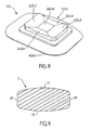
- the core (2) illustrated in Figures 9 and 10, has a substantially parallelepiped shape and has upper (21), lower (22) and lateral (28) and sagittal (29) walls.
- the frontal (28) and sagittal (29) lateral walls are substantially straight, as can be seen in FIGS. 2 and 9.
- the upper (21) and lower (22) walls are rounded in two vertical perpendicular arcuate circles, as shown in FIGS. we can see it on these same figures.
- the upper (21) and lower (22) faces of said core (2) are rounded according to the preferred directions of flexibility of the inner envelope (5).
- angles or edges between the walls of the core (2) are rounded to a small radius of curvature.
- the inner casing (5) has a central cavity (50) in which the core (2) is positioned.
- said core (2) is rigid.
- This cavity (50) has a parallelepipedal shape right, so that in the basic version, empty spaces are formed at the upper and lower end ends, and at the upper and lower sagittal ends of this cavity, between the wall of this cavity and the outer wall of the core (2), as can be seen in Figure 3.
- the inner casing (5) has in horizontal section a cross shape consisting of four horizontal arms (53, 54, 55, 56) oriented perpendicularly.
- These arms extend along the preferred directions of flexibility of the inner envelope (5).
- the arms (53, 54, 55, 56) form a single whole, that is to say that the inner envelope (5) constitutes a single piece.
- the arms (53, 54, 55, 56) each have a hole (57) opening on the upper (51) and lower (52) faces of said inner casing (5), as can be seen in FIGS. and 11, to increase the flexibility of the arms.
- These holes are empty or filled with a fluid or an elastic material.
- centripetal faces (58) of said arms (53, 54, 55, 56) delimiting the cavity (50) are straight.
- centrifugal faces (59) of said arms (53, 54, 55, 56) are rounded to fit the inner faces of the front (68) and sagittal (69) walls of the outer shell (6).
- the inner fins (64) of said outer shell (6) are thus intended to maintain the horizontal arms (53, 54, 55, 56) of the inner shell (5), so as to create additional rigidity in the directions which are not the preferred directions of flexibility of the inner envelope (5).
- the general flexibility of the prosthesis in the basic version is important in the frontal and sagittal planes. Indeed, during the bending of the spine for example forward, as shown in Figure 12, there is displacement of the core (2) in the inner casing (5), towards the rear of the cavity (50 ) and a deformation of the centripetal face (58) rear of the inner casing (5).
- the average axis of the column A at the level of the prosthesis which has moved from the vertical position to the inclined position A 'towards the front, has been rotated relative to the vertical and a translation towards the rear.
- the upper face (21) of the core (2) slides on the inclined planes (33 ', 34') and the lower face (22) of the core (2) slides on the inclined planes (43 ', 44').
- centripetal face (58) of the arm (52) deforms to allow movement of the relatively rigid core (2) and provides an opposing resistance force which is a function of the flexibility of the material used for the inner shell (5).
- the upper plate (3) or the lower plate (4), and preferably the two upper (3) and lower (4) plates (4) have (s) an annular cavity ( 35, 45) adjacent to the outer face (32, 42).
- This annular cavity (35, 45), substantially rectangular, is intended to cooperate with the centripetal rim (63, 63 ') of the outer casing (6).
- the core (2) has a substantially parallelepipedal shape.
- the upper (21), lower (22) walls are therefore substantially horizontal and have no curvature; However, the edges of the walls are still rounded.
- the core (2) is more flexible than in the basic version.
- the general flexibility of the prosthesis is reduced compared to that of the prosthesis according to the basic version. Indeed, during bending forward, as shown in Figure 19, there is no significant displacement of the core (2) in the inner casing (5), as with the base version (see figure 12). The average axis of the column A which has passed from the vertical position to the inclined position A '' has substantially undergone only one rotation relative to the vertical.
- At least one inner face (31, 41), respectively of said upper (3) and / or lower (4) trays, has an appendage (30, 40) constituted, for example, by a half -sphere positioned in the center of the bottom plane (38, 48) of the inner face (31, 41) of the plate and oriented towards the inside of the prosthesis.
- this variant is compatible with the following two variants: the variant in which the inner faces of the plates are flat and the variant in which the outer centrifugal edges of the inner faces of the plates are raised towards the core (2).
- said core (2) comprises respectively on its upper face (21) and / or lower (22) two grooves (23/23 ', 24/24') oriented in two perpendicular directions and intended to cooperate respectively with the appendix (30, 40).
- These grooves have in cross section a semicircular shape having a radius substantially identical to the radius of the semi-spherical shape of the appendix (30, 40).
- Said grooves (23/23 ', 24/24') are oriented in the same directions as the privileged directions of flexibility of the inner envelope (5), that is to say, on the one hand in the direction d left / right lateral inclination for the grooves (23, 24) and secondly in the direction of flexion / extension for the grooves (23 ', 24').
- each groove is adapted according to the desired amplitude for each lateral inclination or flexion / extension movement.
- the ends of the grooves are rounded to the same radius as the radius of the transverse semicircular shape and the intersection point (25, 26) respectively of the two grooves (23, 23 ') on the upper face (21) and the grooves (24, 24 ') on the lower face (22) is arranged to allow the appendix (30, 40) to move in any preferred direction formed by the grooves from this point of intersection.
- the arms (53, 54, 55, 56) each form a single whole, that is to say that the inner envelope (5) consists of four parts: the four arms, as one can see it in Figure 20.
- the horizontal cross shape of the inner casing (5) is thus maintained by the peripheral outer casing (6).
- the arms do not all have the same flexibility. It is, for example, possible to realize the rear arms (54) and front (56) more flexible than the left arm (53) and right (55). Thus, the flexibility of the prosthesis is greater in flexion / extension movements than in lateral inclination movements.
- the inner envelope (5) and the outer envelope (6) form a single piece, possibly having non-uniform intrinsic characteristics.
- said one or more upper (3) and / or lower (4) plates have (s) on its or their outer face (s) (32, 42) a fixing rail (36, 46).
- This fixing rail is oriented substantially in the sagittal direction of flexion / extension. It consists of a longitudinal bridge connected to the outer face (32, 42) of the plate (3, 4) by at least one pillar (39, 49), and preferably three pillars (39, 49). Between each pillar, a light is arranged, to allow to pass a fastening means (7, 8).
- each upper (7) and lower (8) fastening means consists of an intersomatic cage of the type disclosed in the patent application.
- French N ° FR 02/01654 comprising a central hollow space delimited by a helical structure (71, 81) composed of helical turns not axially joined and comprising, at one axial end, a gripping means.
- the upper (7) and lower (8) fixing means thus make it possible respectively to fix the plates (3, 4) to the overlying and underlying bone walls of the vertebral column.
- the helical spiral can be inserted by screwing it on the one hand into the vertebrae and on the other hand into the lights arranged between the pillars of the rail.
- the intervertebral prosthesis (1) advantageously consists of two cores (200, 210) having cross-shaped grooves so as to confer the anatomical directions.
- the inner casing (5) has a longitudinal flexible membrane (500) extending in a median plane so as to form two cavities for respectively receiving said cores (200, 210).
- the membrane (500) of said inner casing (5) is made of flexible polymer.
- the upper and lower trays (3, 4) respectively have a through hole (310, 410).
- the through hole (310, 410) is extended by a threaded tubular zone (300, 400) to allow screwing on each of said plates (3, 4) of a contact element (7, 8).
- These contact elements (7, 8) are intended to be in contact respectively with the overlying and underlying vertebrae.
- the opening on either side of the trays (3, 4) thus allows the injection of a fluid into the two cavities of the inner casing (5).
- the fluid injected into each of the cavities of the inner envelope (5) through respectively each of said plates (3, 4) constitutes the two cores (200, 210) of the intervertebral prosthesis (1).
- the latter are advantageously overmoulded, prior to screwing the contact elements on the plates (3, 4), with a flexible elastomer (9).
Landscapes
- Health & Medical Sciences (AREA)
- Engineering & Computer Science (AREA)
- Biomedical Technology (AREA)
- Orthopedic Medicine & Surgery (AREA)
- Neurology (AREA)
- Heart & Thoracic Surgery (AREA)
- General Health & Medical Sciences (AREA)
- Transplantation (AREA)
- Cardiology (AREA)
- Vascular Medicine (AREA)
- Life Sciences & Earth Sciences (AREA)
- Animal Behavior & Ethology (AREA)
- Oral & Maxillofacial Surgery (AREA)
- Public Health (AREA)
- Veterinary Medicine (AREA)
- Prostheses (AREA)
- Medicines That Contain Protein Lipid Enzymes And Other Medicines (AREA)
- Medicines Containing Material From Animals Or Micro-Organisms (AREA)
- Ultra Sonic Daignosis Equipment (AREA)
Abstract
Description
La présente invention se rapporte au domaine des prothèses de disques intervertébraux.The present invention relates to the field of intervertebral disc prostheses.
La présente invention se rapporte plus particulièrement à une prothèse intervertébrale du type constituée au moins d'un noyau positionné entre un plateau supérieur et un plateau inférieur, ladite prothèse comportant en outre au moins une enveloppe externe.The present invention relates more particularly to an intervertebral prosthesis of the type consisting of at least one core positioned between an upper plate and a lower plate, said prosthesis further comprising at least one outer casing.
Le document
L'art antérieur connaît déjà des prothèses intervertébrales de ce type.The prior art already knows intervertebral prostheses of this type.
Il est ainsi proposé dans le brevet américain N° 5 674 296, une endoprothèse de disque vertébral comprenant un noyau, de préférence un noyau élastique, des éléments rigides ayant des surfaces internes concaves entourant au moins en partie le noyau. L'endoprothèse comprend aussi un élément d'étanchéité formé de matériau flexible, fixé aux éléments rigides et entourant le noyau.It is thus proposed in US Pat. No. 5,674,296, a spinal disc endoprosthesis comprising a core, preferably an elastic core, rigid elements having concave internal surfaces surrounding at least part of the core. The stent also includes a sealing member formed of flexible material attached to the rigid members and surrounding the core.
Cette endoprothèse vertébrale de disque (18) comporte un noyau flexible (20, 24), des plateaux concaves-convexes rigides (30, 32, 34) disposés au-dessus et en dessous du noyau, un anneau de garniture périphérique (22) relativement rigide entourant le noyau (20, 24), et un membre de joint (110) constitué d'un matériau flexible, attaché aux plateaux concaves-convexes et entourant le noyau et l'anneau de garniture.The disk spinal endoprosthesis (18) has a flexible core (20, 24), rigid concave-convex plates (30, 32, 34) disposed above and below the core, a relatively peripheral ring (22). rigid surrounding the core (20, 24), and a joint member (110) made of a flexible material, attached to the concave-convex plates and surrounding the core and the packing ring.
Chaque plateau concave-convexe est d'épaisseur en coupe relativement constante et présente d'une part une surface convexe externe pour s'engager dans la structure adjacente d'os qui a été préalablement fraisée et d'autre part une surface concave intérieure correspondante pour retenir le corps résilient du noyau.Each concave-convex plate is of relatively constant cross-sectional thickness and has on the one hand an external convex surface for engaging in the adjacent bone structure which has been previously milled and on the other hand a corresponding inner concave surface for retain the resilient body of the nucleus.
Dans cette prothèse, la forme des faces intérieures des plateaux est identique à la forme du noyau adjacent et le noyau est ainsi strictement immobile.In this prosthesis, the shape of the inner faces of the trays is identical to the shape of the adjacent nucleus and the core is thus strictly immobile.
Les prothèses de l'art antérieur ne donnent pas satisfaction car elles ne permettent pas de guider et d'amortir les déplacements des vertèbres sous-jacentes et sus-jacentes, comme le fond les disques anatomiques.Prostheses of the prior art are unsatisfactory because they do not guide and cushion the movements of the underlying and overlying vertebrae, as the bottom anatomical discs.
La présente invention entend remédier aux inconvénients de l'art antérieur en proposant une prothèse qui à la fois guide et amorti les mouvements de flexion/extension avant/arrière et d'inclinaison gauche/droite des vertèbres sous-jacentes et sus-jacentes.The present invention intends to overcome the drawbacks of the prior art by providing a prosthesis that both guides and damps the movements of flexion / extension forward / backward and left / right inclination of the underlying and overlying vertebrae.
Pour ce faire, la présente invention est comme définie par le revendication 1 et elle est remarquable, dans son acception la plus large, en ce que lesdits plateaux comportent respectivement des faces intérieures qui permettent un mouvement du noyau à l'intérieur de ladite prothèse.To do this, the present invention is as defined by
Ledit noyau est, de préférence, entouré latéralement d'une enveloppe interne souple, ladite enveloppe interne présentant des directions privilégiées de flexibilité, de préférence au nombre de deux et orientées perpendiculairement.Said core is preferably laterally surrounded by a flexible inner envelope, said inner envelope having preferred directions of flexibility, preferably two in number and oriented perpendicularly.
Ladite enveloppe externe est, de préférence, souple.Said outer envelope is preferably flexible.
De préférence au moins une face intérieure, respectivement desdits plateaux supérieur et/ou inférieur et de manière encore plus préférée les deux faces intérieures des plateaux, présente(nt) des moyens de guidage de déplacement dudit noyau.Preferably at least one inner face, respectively of said upper and / or lower trays and even more preferably the two inner faces of the trays, has (s) displacement guiding means of said core.
Lesdits moyens de guidage sont, de préférence, orientés selon deux directions perpendiculaires et de préférence dans les mêmes directions que les directions privilégiées de flexibilité de l'enveloppe interne.Said guide means are preferably oriented in two perpendicular directions and preferably in the same directions as the preferred directions of flexibility of the inner envelope.
Lesdits moyens de guidages sont, de préférence, constitués par des plans inclinés dont les bords extérieurs sont orientés vers le noyau.Said guide means are preferably constituted by inclined planes whose outer edges are oriented towards the core.
Dans une variante, au moins une face intérieure, respectivement desdits plateaux supérieur et/ou inférieur présente, de préférence, un appendice et ledit noyau comporte, de préférence, en outre respectivement sur sa face supérieure et/ou inférieure deux rainures orientées selon deux directions perpendiculaires.In a variant, at least one inner face, respectively of said upper and / or lower trays, preferably has an appendage and said core preferably comprises, in addition, respectively on its upper face and / or lower two grooves oriented in two directions. perpendicular.
Dans cette variante, lesdites rainures sont, de préférence, orientées dans les mêmes directions que les directions privilégiées de flexibilité de l'enveloppe interne.In this variant, said grooves are preferably oriented in the same directions as the preferred directions of flexibility of the inner envelope.
Dans une variante, au moins une face intérieure, respectivement desdits plateaux supérieur et/ou inférieur, et de préférence les deux faces intérieures des plateaux, est ou sont plate(s).In a variant, at least one inner face, respectively of said upper and / or lower trays, and preferably the two inner faces of the trays, is or are flat (s).
Ledit noyau présente, de préférence, une forme sensiblement parallélépipédique.Said core preferably has a substantially parallelepipedal shape.
Les faces supérieure et inférieure dudit noyau sont, de préférence, arrondies selon les directions privilégiées de flexibilité de l'enveloppe interne.The upper and lower faces of said core are preferably rounded according to the preferred directions of flexibility of the inner envelope.
Ledit noyau présente, de préférence, des bords arrondis.Said core preferably has rounded edges.
Ladite enveloppe interne présente, de préférence, en coupe horizontale une forme de croix constituée de quatre bras horizontaux orientés perpendiculairement.Said inner casing has, preferably, in horizontal section a form of cross consisting of four horizontal arms oriented perpendicularly.
Lesdits bras présentent, de préférence, chacun un trou débouchant sur les faces supérieure et inférieure de ladite enveloppe interne.Said arms preferably each have a hole opening on the upper and lower faces of said inner envelope.
Les faces centripètes desdits bras sont, de préférence, droites et les faces centrifuges desdits bras sont, de préférence, arrondies.The centripetal faces of said arms are preferably straight and the centrifugal faces of said arms are preferably rounded.
Ladite enveloppe externe présente, de préférence, des ailettes intérieures destinées à maintenir les bras horizontaux de l'enveloppe interne, à l'angle entre les bras de la forme en croix.Said outer casing preferably has inner fins for holding the arms horizontal of the inner envelope, at the angle between the arms of the cross-shaped.
Dans une variante, l'enveloppe interne et l'enveloppe externe sont venues de matière.In a variant, the inner envelope and the outer envelope are made of material.
Ladite enveloppe externe est, de préférence, ajourée sur ses parois supérieure et/ou inférieure, pour le passage des faces extérieures, respectivement des plateaux supérieur et inférieur.Said outer envelope is preferably perforated on its upper and / or lower walls, for the passage of the outer faces, respectively of the upper and lower trays.
Dans une autre variante, ledit ou lesdits plateau(x) supérieur et/ou inférieur présente(nt) une cavité annulaire adjacente à la face extérieure et ladite ou lesdites paroi(s) respectivement supérieure et/ou inférieure présente(nt) un rebord centripète destiné à coopérer avec ladite cavité annulaire.In another variant, said at least one upper and / or lower plate (s) has (s) an annular cavity adjacent to the outer face and said one or more walls (s) respectively upper and / or lower has (s) a centripetal rim. intended to cooperate with said annular cavity.
Dans une autre variante, ledit ou lesdits plateau(x) supérieur et/ou inférieur est ou sont souple(s).In another variant, said one or more upper and / or lower platen (s) is or are flexible (s).
Dans une autre variante, ledit ou lesdits plateau(x) supérieur et/ou inférieur présente(nt) sur sa ou sur leurs face(s) extérieure(s) un rail de fixation.In another variant, said one or more upper and / or lower platen (s) has (s) on its or on their outer face (s) a fixing rail.
La prothèse comporte en outre, de préférence, des moyens de fixation pour la fixation respectivement du ou des plateau(x) supérieur et/ou inférieur.The prosthesis furthermore preferably comprises fastening means for fastening the upper and / or lower plate (s) respectively.
Dans un mode de réalisation avantageux de l'invention, la prothèse intervertébrale comporte deux noyaux.In an advantageous embodiment of the invention, the intervertebral prosthesis comprises two cores.
De préférence, l'enveloppe interne présente une membrane médiane longitudinale séparant les noyaux.Preferably, the inner envelope has a longitudinal median membrane separating the nuclei.
Avantageusement, la membrane de ladite enveloppe interne est flexible.Advantageously, the membrane of said inner casing is flexible.
Avantageusement, un des plateaux au moins comporte un orifice traversant pour permettre le passage d'un fluide dans ladite enveloppe interne.Advantageously, at least one of the trays has a through orifice to allow the passage of a fluid in said inner casing.
Avantageusement, l'orifice traversant est prolongé par une zone tubulaire filetée destinée à coopérer avec une zone filetée complémentaire d'un élément de contact destinée à être mis au contact avec une des vertèbres.Advantageously, the through orifice is extended by a threaded tubular zone intended to cooperate with a complementary threaded zone of a contact element intended to be brought into contact with one of the vertebrae.
Avantageusement, ladite prothèse formée du ou des noyaux, de l'enveloppe interne, de l'enveloppe externe et des plateaux est surmoulé avec un élastomère souple.Advantageously, said prosthesis formed of the core or cores, the inner casing, the outer casing and the trays is overmolded with a flexible elastomer.
Avantageusement, le(s)dit(s) noyau(x) est (sont) solide(s) ou liquide(s).Advantageously, said core (s) is (are) solid (s) or liquid (s).
Avantageusement, la présente invention permet de restaurer les mouvements naturels des vertèbres sous-jacentes et sus-jacentes, ou, au besoin, limiter certaines capacités de mouvement dans une direction ou une autre.Advantageously, the present invention makes it possible to restore the natural movements of the underlying and overlying vertebrae, or, if necessary, to limit certain movement capacities in one direction or another.
Avantageusement également, il est possible de choisir des matériaux constitutifs en fonction des résistances croissantes au mouvement souhaitées et en fonction des directions privilégiées de flexibilité souhaitées pour chacune des pièces :
- le plateau supérieur et/ou inférieur, et/ou
- le noyau, et/ou
- l'enveloppe interne, et/ou
- l'enveloppe externe.
- the top and / or bottom plate, and / or
- the kernel, and / or
- the inner envelope, and / or
- the outer envelope.
Avantageusement également, la présente invention permet une bonne absorption des chocs.Advantageously also, the present invention allows good shock absorption.
Elle permet en outre de préserver les facettes articulaires.It also makes it possible to preserve the facet joints.
Elle présente une grande fiabilité dans le temps.It has a high reliability over time.
Elle est en outre simple à implanter.It is also easy to implant.
On comprendra mieux l'invention à l'aide de la description, faite ci-après à titre purement explicatif, d'un mode de réalisation de l'invention, en référence aux figures annexées :
- la figure 1 illustre une vue en perspective de la version de base de la prothèse selon l'invention ;
- la figure 2 illustre une vue éclatée de la version de base de la prothèse selon l'invention;
- la figure 3 illustre une vue en coupe verticale selon AA de la figure 1 ;
- la figure 4 illustre une vue en perspective de la coupe horizontale partielle selon BB de la figure 1 ;
- la figure 5 illustre une vue de dessus de la coupe horizontale partielle selon BB de la figure 1 ;
- la figure 6 illustre une vue de dessus de la version de base de la prothèse selon l'invention, sans le plateau supérieur ;
- la figure 7 illustre une vue en coupe verticale selon AA de la figure 1 de l'enveloppe externe de la version de base de la prothèse selon l'invention ;
- la figure 8 illustre une vue en perspective d'un plateau pour la version de base de la prothèse selon l'invention ;
- la figure 9 illustre une vue en coupe verticale selon AA de la figure 1 du noyau de la version de base de la prothèse selon l'invention ;
- la figure 10 illustre une vue en coupe transversale du noyau de la version de base de la prothèse selon l'invention ;
- la figure 11 illustre une vue en coupe verticale selon AA de la figure 1 de l'enveloppe interne de la version de base de la prothèse selon l'invention ;
- la figure 12 illustre une vue en coupe verticale selon AA de la figure 1 de la version de base de la prothèse selon l'invention lors d'un mouvement de flexion ;
- la figure 13 illustre la déformation de l'enveloppe externe lors du mouvement illustré figure 12 ;
- la figure 14 illustre une vue en coupe verticale et en perspective d'une variante de l'invention dans laquelle les plateaux supérieur et inférieur sont clipés dans l'enveloppe externe ;
- la figure 15 illustre une vue en perspective d'un plateau pour la variante illustrée figure 14;
- la figure 16 illustre une vue éclatée d'une variante de l'invention dans laquelle le noyau présente une forme de parallélépipède droit et dans laquelle l'enveloppe interne est constituée de quatre bras séparés ;
- la figure 17 est une vue en coupe verticale et en perspective de la variante de la figure 16 assemblée ;
- la figure 18 est une vue en coupe horizontale partielle et en perspective de la variante de la figure 16 assemblée ;
- la figure 19 illustre une vue en coupe verticale de la variante de la figure 16 lors d'un mouvement de flexion ;
- la figure 20 illustre une vue éclatée d'une variante de l'invention dans laquelle le noyau présente une forme de parallélépipède à faces supérieur et inférieur arrondie et munies de rainures, dans laquelle les plateaux supérieur et inférieur sont munis d'un appendice destiné à coopérer avec lesdites rainures et dans laquelle l'enveloppe interne est constituée de quatre bras séparés ;
- la figure 21 est une vue en coupe verticale et en perspective de la variante de la figure 20 assemblée;
- la figure 22 est une vue en coupe horizontale partielle et en perspective de la variante de la figure 20 assemblée;
- la figure 23 illustre une vue en perspective du noyau de la variante de la figure 20;
- la figure 24 illustre une vue en coupe longitudinale du noyau pour la variante de la figure 20 ;
- la figure 25 illustre une vue en perspective d'un plateau pour la variante de la figure 20 ;
- la figure 26 illustre une vue en perspective d'une variante de l'invention dans laquelle les plateaux supérieur et inférieur sont munis d'un rail de fixation ;
- la figure 27 illustre une vue de côté de la variante de la figure 26 ;
- la figure 28 illustre une vue en perspective d'un plateau pour la variante de la figure 26 ;
- la figure 29 illustre une vue en perspective d'une prothèse selon la variante de la figure 26 munie de moyens de fixation pour sa fixation aux vertèbres ; et
- la figure 30 illustre une vue éclatée d'une autre variante de la prothèse intervertébrale selon l'invention ;
- la figure 31 illustre une vue en coupe verticale en en perspective de la prothèse de la figure 30 assemblée ;
- la figure 32 illustre une vue de dessus et en perspective d'un plateau constituant la prothèse de la figure 30 ; et
- la figure 33 illustre une vue en coupe et en perspective du plateau de la figure 32.
- Figure 1 illustrates a perspective view of the basic version of the prosthesis according to the invention;
- Figure 2 illustrates an exploded view of the basic version of the prosthesis according to the invention;
- Figure 3 illustrates a vertical sectional view along AA of Figure 1;
- Figure 4 illustrates a perspective view of the partial horizontal section along BB of Figure 1;
- Figure 5 illustrates a top view of the partial horizontal section along BB of Figure 1;
- FIG. 6 illustrates a view from above of the basic version of the prosthesis according to the invention, without the upper plate;
- Figure 7 illustrates a vertical sectional view along AA of Figure 1 of the outer casing of the basic version of the prosthesis according to the invention;
- Figure 8 illustrates a perspective view of a tray for the basic version of the prosthesis according to the invention;
- Figure 9 illustrates a vertical sectional view along AA of Figure 1 of the core of the basic version of the prosthesis according to the invention;
- Figure 10 illustrates a cross-sectional view of the core of the basic version of the prosthesis according to the invention;
- Figure 11 illustrates a vertical sectional view along AA of Figure 1 of the inner casing of the basic version of the prosthesis according to the invention;
- Figure 12 illustrates a vertical sectional view along AA of Figure 1 of the basic version of the prosthesis according to the invention during a bending movement;
- FIG. 13 illustrates the deformation of the outer envelope during the movement illustrated in FIG. 12;
- FIG. 14 illustrates a view in vertical section and in perspective of a variant of the invention in which the upper and lower trays are clipped into the outer envelope;
- Figure 15 illustrates a perspective view of a tray for the variant shown in Figure 14;
- FIG. 16 illustrates an exploded view of a variant of the invention in which the core has a right parallelepiped shape and in which the inner envelope consists of four separate arms;
- Figure 17 is a vertical sectional perspective view of the variant of Figure 16 assembled;
- Figure 18 is a partial horizontal sectional perspective view of the variant of Figure 16 assembled;
- Figure 19 illustrates a vertical sectional view of the variant of Figure 16 in a bending motion;
- FIG. 20 illustrates an exploded view of a variant of the invention in which the core has a parallelepiped shape with upper and lower faces rounded and provided with grooves, in which the upper and lower trays are provided with an appendage intended for cooperating with said grooves and wherein the inner envelope consists of four separate arms;
- Figure 21 is a vertical sectional perspective view of the variant of Figure 20 assembled;
- Figure 22 is a partial and perspective horizontal sectional view of the alternative of Figure 20 assembled;
- Fig. 23 illustrates a perspective view of the core of the variant of Fig. 20;
- Fig. 24 illustrates a longitudinal sectional view of the core for the variant of Fig. 20;
- Fig. 25 illustrates a perspective view of a tray for the variant of Fig. 20;
- Figure 26 illustrates a perspective view of a variant of the invention in which the upper and lower trays are provided with a fixing rail;
- Figure 27 illustrates a side view of the variant of Figure 26;
- Figure 28 illustrates a perspective view of a tray for the variant of Figure 26;
- Figure 29 illustrates a perspective view of a prosthesis according to the variant of Figure 26 provided with fixing means for attachment to the vertebrae; and
- Figure 30 illustrates an exploded view of another variant of the intervertebral prosthesis according to the invention;
- Figure 31 illustrates a perspective vertical sectional view of the prosthesis of the assembled figure;
- FIG. 32 illustrates a view from above and in perspective of a plate constituting the prosthesis of FIG. 30; and
- Figure 33 illustrates a sectional and perspective view of the plate of Figure 32.
La prothèse selon la présente invention, illustrée dans sa version de base sur la figure 1, est une prothèse intervertébrale (1) du type constituée au moins d'un noyau (2) positionné entre un plateau supérieur (3) et un plateau inférieur (4).The prosthesis according to the present invention, illustrated in its basic version in FIG. 1, is an intervertebral prosthesis (1) of the type consisting of at least one core (2) positioned between an upper plate (3) and a lower plate ( 4).
Dans cette version de base les plateaux (3, 4) sont rigides.In this basic version the trays (3, 4) are rigid.
Cette prothèse est destinée à être positionnée entre deux vertèbres, à la place d'un disque, lorsque celui-ci est défaillant et provoque des douleurs.This prosthesis is intended to be positioned between two vertebrae, instead of a disk, when it is faulty and causes pain.
Les plateaux supérieur (3) et inférieur (4) présentent respectivement une face intérieure (31, 41).The upper (3) and lower (4) plates respectively have an inner face (31, 41).
Le plateau supérieur (3) présente une face extérieure (32) destinée à coopérer avec la face inférieure de la vertèbre située au-dessus de la prothèse et le plateau inférieur (4) présente une face extérieure (42) destinée à coopérer avec la face supérieure de la vertèbre située au-dessous de la prothèse. Les faces extérieures (32, 42) sont sensiblement horizontales.The upper plate (3) has an outer face (32) intended to cooperate with the lower face of the vertebra located above the prosthesis and the lower plate (4) has an outer face (42) intended to cooperate with the face. vertebrae below the prosthesis. The outer faces (32, 42) are substantially horizontal.
Le but de la prothèse selon l'invention est de se substituer complètement au disque douloureux et de permettre à nouveau les mouvements des vertèbres situées au-dessus et en dessous, les unes par rapport aux autres, comme lorsque le disque n'était pas défaillant.The purpose of the prosthesis according to the invention is to completely replace the painful disc and to allow again the movements of the vertebrae located above and below, relative to each other, as when the disc was not defective .
Pour autoriser ces mouvements des vertèbres, ledit noyau (2) est mobile à l'intérieur de la prothèse, entre les faces intérieures (31, 41) des plateaux (3, 4).To allow these movements of the vertebrae, said core (2) is movable inside the prosthesis, between the inner faces (31, 41) of the plates (3, 4).
La mobilité du noyau (2) est essentiellement horizontale et engendre une modification du centre de gravité de la prothèse.The mobility of the core (2) is essentially horizontal and causes a change in the center of gravity of the prosthesis.
La forme des faces intérieures (31, 41) est complémentaire de la forme du noyau adjacent, sans être complètement identique, de manière à autoriser le déplacement du noyau (2) par rapport aux plateaux.The shape of the inner faces (31, 41) is complementary to the shape of the adjacent core, without being completely identical, so as to allow the displacement of the core (2) relative to the trays.
Le noyau (2) est entouré latéralement d'une enveloppe interne (5). Cette enveloppe interne (5) est souple et présente des directions privilégiées de flexibilité. Ladite prothèse (1) comporte en outre une enveloppe externe (6) également souple.The core (2) is laterally surrounded by an inner envelope (5). This inner envelope (5) is flexible and has preferred directions of flexibility. Said prosthesis (1) further comprises an outer envelope (6) also flexible.
Cette enveloppe externe (6) contient l'enveloppe interne (5), qui elle-même contient le noyau (2), comme on peut le voir sur les figures 2 à 5.This outer envelope (6) contains the inner envelope (5), which itself contains the core (2), as can be seen in Figures 2 to 5.
Ladite enveloppe interne (5) présente deux directions privilégiées de flexibilité orientées perpendiculairement, afin de permettre de restaurer d'une part les mouvements d'inclinaison latérales gauche/droite et d'autre part les mouvements de flexion/extension, les mouvements de rotation étant restaurés notamment à l'intersection des deux directions privilégiés autorisant respectivement les inclinaisons gauche/droite et les mouvements de flexion/extension.Said internal envelope (5) has two privileged directions of flexibility oriented perpendicularly, to allow restoring on the one hand the left / right lateral inclination movements and on the other hand the bending / extension movements, the rotational movements being restored in particular at the intersection of the two privileged directions respectively authorizing left / right inclinations and flexion / extension movements.
Les éléments souples de la prothèse selon l'invention peuvent être constitués d'éléments réalisés en bio matériau (polyuréthane, polycarbonate, polyvinyle alcool, ...) et les éléments rigides peuvent être constitués d'éléments réalisés en bio matériau ou en métal ou alliage métallique.The flexible elements of the prosthesis according to the invention may consist of elements made of bio-material (polyurethane, polycarbonate, polyvinyl alcohol, etc.) and the rigid elements may consist of elements made of bio-material or metal or metal alloy.
L'enveloppe externe (6) présente une forme générale parallélépipédique et comporte des parois supérieure (61), inférieure (62) et latérales frontales (68) et sagittales (69). Les parois latérales frontales (68) sont sensiblement arrondies selon un arc de cercle vertical, comme on peut le voir sur la figure 3, alors que les parois latérales sagittales (69) sont arrondies à la fois selon un arc de cercle horizontal et selon un arc de cercle vertical, comme on peut le voir sur les figures 5 à 7. Les parois supérieure (61) et inférieure (62) sont sensiblement plates.The outer shell (6) has a generally parallelepipedal shape and has upper (61), lower (62) and lateral (68) and sagittal (69) walls. The front side walls (68) are substantially rounded in a vertical arc of a circle, as can be seen in FIG. 3, while the sagittal side walls (69) are rounded at a time in a horizontal arc and in a vertical arc of a circle, as can be seen in Figures 5 to 7. The upper walls (61) and lower (62) are substantially flat.
Les angles entre les parois de l'enveloppe externe (6) sont arrondis selon un faible rayon de courbure.The angles between the walls of the outer envelope (6) are rounded to a small radius of curvature.
L'enveloppe externe (6) présente une cavité intérieure (60) en forme de croix en coupe horizontale, comme on peut le voir sur la figure 5, dans laquelle est positionnée l'enveloppe interne (5).The outer casing (6) has an inner cavity (60) cross-shaped in horizontal section, as can be seen in Figure 5, in which is positioned the inner casing (5).
L'enveloppe externe (6) présente un trou (67) sur ses parois supérieure (61) et inférieure (62), comme on peut le voir sur la figure 6, pour le passage des faces extérieures (32, 42), respectivement des plateaux supérieur (3) et inférieur (4).The outer casing (6) has a hole (67) on its upper (61) and lower (62) walls, as can be seen in Figure 6, for the passage of the outer faces (32, 42), respectively upper (3) and lower (4) trays.
Les parois latérales frontales (68) et sagittales (69) présentent une épaisseur sensiblement constante.The front (68) and sagittal (69) side walls have a substantially constant thickness.
Ladite paroi supérieure (61) ou inférieure (62), et de préférence les deux parois supérieure (61) et inférieure (62), présente(nt) respectivement un rebord centripète (63, 63'), ménagé vers l'intérieur, sur lequel/lesquels vient/viennent se reposer la/les face(s) extérieure(s) (32, 42) du/des plateau(x) supérieur (3) et/ou inférieur (4), comme on peut le voir sur la figure 3.
ladite enveloppe externe (6) présente des ailettes intérieures (64) horizontales, positionnées dans la partie inférieure et supérieure de la paroi intérieure de l'enveloppe et orientées vers l'intérieur.Said upper (61) or lower (62) wall, and preferably both upper (61) and lower (62) walls, respectively, have a centripetal rim (63, 63 '), arranged inward, on which / which comes / rest the outer surface (s) (32, 42) of the upper (3) and / or lower (4) plate (s), as can be seen on the figure 3.
said outer casing (6) has horizontal inner fins (64) positioned in the portion bottom and top of the inner wall of the casing and facing inwards.
La cavité intérieure (60) présente donc à la fois une forme de croix en coupe horizontale et une forme de croix en coupe verticale, comme on peut le constater sur la figure 7.The inner cavity (60) thus has both a cross shape in horizontal section and a cross shape in vertical section, as can be seen in Figure 7.
La flexibilité et la souplesse de l'enveloppe externe (6) permettent de maintenir l'ensemble des éléments constitutifs de la prothèse et participent à l'amortissement vertical, c'est-à-dire à la résistance à la compression.The flexibility and flexibility of the outer casing (6) maintain all the components of the prosthesis and participate in the vertical damping, that is to say, the compressive strength.
Cette flexibilité et cette souplesse de l'enveloppe externe (6) permettent également de réaliser un amortissement et un retour à la position centrale lors des mouvements de rotation, afin d'apporter une limitation dans ces mouvements.This flexibility and flexibility of the outer casing (6) also allow damping and a return to the central position during rotational movements, to provide a limitation in these movements.
Comme illustré figure 8, les deux faces intérieures (31, 41) présentent des moyens de guidage de déplacement dudit noyau (2), lesdits moyens de guidage étant orientés selon deux directions perpendiculaires.As illustrated in FIG. 8, the two inner faces (31, 41) have means for guiding the displacement of said core (2), said guide means being oriented in two perpendicular directions.
Ces moyens de guidages sont orientés dans les mêmes directions que les directions privilégiées de flexibilité de l'enveloppe interne (5).These guide means are oriented in the same directions as the preferred directions of flexibility of the inner envelope (5).
Lesdits moyens de guidages sont constitués, pour le plateau supérieur (3) par des plans inclinés (33, 33', 34, 34') dont les bords extérieurs sont abaissés vers le noyau (2), c'est-à-dire vers le bas, et par un plan de fond (38) horizontal et pour le plateau inférieur (4) par des plans inclinés (43, 43', 44, 44') dont les bords extérieurs sont relevés vers le noyau (2), c'est-à-dire vers le haut, et par un plan de fond (48) horizontal.Said guide means are constituted, for the upper plate (3) by inclined planes (33, 33 ', 34, 34') whose outer edges are lowered towards the core (2), that is to say towards at the bottom, and by a horizontal bottom plane (38) and for the lower plate (4) by inclined planes (43, 43 ', 44, 44') whose outer edges are raised towards the core (2), c that is to say upwards, and by a horizontal bottom plane (48).
Les plateaux supérieur (3) et inférieur (4) comportent en outre chacun un rebord (37, 47) rectangulaire, horizontal, situé entre la face intérieure (31, 41) et la face extérieure (32, 42), de taille supérieure à la face intérieure (31, 41) et de taille inférieure à la face extérieure (32, 42). Ces rebords (37, 47) sont destinés à être insérés dans les trous (67) ménagés dans les parois supérieure (61) et inférieure (62) de l'enveloppe externe (6).The upper (3) and lower (4) plates each further comprise a rectangular rim (37, 47), horizontal, situated between the inner face (31, 41) and the outer face (32, 42), larger than the inner face (31, 41) and smaller than the face outside (32, 42). These flanges (37, 47) are intended to be inserted into the holes (67) formed in the upper (61) and lower (62) walls of the outer casing (6).
Dans une variante de la version de base, un plateau, et de préférence les deux plateaux supérieur (3) et inférieur (4), est ou sont souple(s). Cette variante est avantageusement associée avec la variante de l'invention à noyau rigide.In a variant of the basic version, a plate, and preferably the two upper (3) and lower (4) plates, is or are flexible (s). This variant is advantageously associated with the variant of the invention with a rigid core.
Dans cette variante à plateaux souples, la souplesse des plateaux favorise l'amortissement vertical et augmente l'aptitude des plateaux à se conformer à la configuration des parois osseuses adjacentes.In this variant with flexible plates, the flexibility of the trays promotes vertical damping and increases the ability of the trays to conform to the configuration of the adjacent bone walls.
Le noyau (2), illustré figures 9 et 10, présente une forme sensiblement parallélépipédique et comporte des parois supérieure (21), inférieure (22) et latérales frontales (28) et sagittales (29). Les parois latérales frontales (28) et sagittales (29) sont sensiblement droites, comme on peut le voir sur les figures 2 et 9. Les parois supérieure (21), inférieure (22) sont arrondies selon deux arc de cercle verticaux perpendiculaires, comme on peut le voir sur ces mêmes figures.The core (2), illustrated in Figures 9 and 10, has a substantially parallelepiped shape and has upper (21), lower (22) and lateral (28) and sagittal (29) walls. The frontal (28) and sagittal (29) lateral walls are substantially straight, as can be seen in FIGS. 2 and 9. The upper (21) and lower (22) walls are rounded in two vertical perpendicular arcuate circles, as shown in FIGS. we can see it on these same figures.
Les faces supérieure (21) et inférieure (22) dudit noyau (2) sont arrondies selon les directions privilégiées de flexibilité de l'enveloppe interne (5).The upper (21) and lower (22) faces of said core (2) are rounded according to the preferred directions of flexibility of the inner envelope (5).
Les angles ou bords entre les parois du noyau (2) sont arrondis selon un faible rayon de courbure.The angles or edges between the walls of the core (2) are rounded to a small radius of curvature.
L'enveloppe interne (5) présente une cavité centrale (50) dans laquelle est positionné le noyau (2).The inner casing (5) has a central cavity (50) in which the core (2) is positioned.
Dans la version de base de l'invention, ledit noyau (2) est rigide.In the basic version of the invention, said core (2) is rigid.
Cette cavité (50) présente une forme de parallélépipède droit, de sorte que dans la version de base, des espaces vides sont ménagés aux extrémités frontales supérieure et inférieure, ainsi qu'aux extrémités sagittales supérieure et inférieure de cette cavité, entre la paroi de cette cavité et la paroi extérieure du noyau (2), comme on peut le constater sur la figure 3.This cavity (50) has a parallelepipedal shape right, so that in the basic version, empty spaces are formed at the upper and lower end ends, and at the upper and lower sagittal ends of this cavity, between the wall of this cavity and the outer wall of the core (2), as can be seen in Figure 3.
L'enveloppe interne (5) présente en coupe horizontale une forme de croix constituée de quatre bras horizontaux (53, 54, 55, 56) orientés perpendiculairement.The inner casing (5) has in horizontal section a cross shape consisting of four horizontal arms (53, 54, 55, 56) oriented perpendicularly.
Ces bras (53, 54, 55, 56) s'étendent selon les directions privilégiées de flexibilité de l'enveloppe interne (5).These arms (53, 54, 55, 56) extend along the preferred directions of flexibility of the inner envelope (5).
Dans la version de base de l'invention, les bras (53, 54, 55, 56) forment un tout unique, c'est-à-dire que l'enveloppe interne (5) constitue une seule pièce.In the basic version of the invention, the arms (53, 54, 55, 56) form a single whole, that is to say that the inner envelope (5) constitutes a single piece.
Les bras (53, 54, 55, 56) présent chacun un trou (57) débouchant sur les faces supérieure (51) et inférieure (52) de ladite enveloppe interne (5), comme on peut le voir sur les figures 4, 5 et 11, afin d'augmenter la flexibilité des bras. Ces trous sont vides ou remplis d'un fluide ou d'une matière élastique.The arms (53, 54, 55, 56) each have a hole (57) opening on the upper (51) and lower (52) faces of said inner casing (5), as can be seen in FIGS. and 11, to increase the flexibility of the arms. These holes are empty or filled with a fluid or an elastic material.
Les faces centripètes (58) desdits bras (53, 54, 55, 56), délimitant la cavité (50) sont droites.The centripetal faces (58) of said arms (53, 54, 55, 56) delimiting the cavity (50) are straight.
Les faces centrifuges (59) desdits bras (53, 54, 55, 56) sont arrondies pour s'adapter aux faces intérieures des parois frontales (68) et sagittales (69) de l'enveloppe externe (6).The centrifugal faces (59) of said arms (53, 54, 55, 56) are rounded to fit the inner faces of the front (68) and sagittal (69) walls of the outer shell (6).
Les ailettes intérieures (64) de ladite enveloppe externe (6) sont ainsi destinées à maintenir les bras horizontaux (53, 54, 55, 56) de l'enveloppe interne (5), de manière à créer une rigidité supplémentaire dans les directions qui ne sont pas les directions privilégiées de flexibilité de l'enveloppe interne (5).The inner fins (64) of said outer shell (6) are thus intended to maintain the horizontal arms (53, 54, 55, 56) of the inner shell (5), so as to create additional rigidity in the directions which are not the preferred directions of flexibility of the inner envelope (5).
La flexibilité générale de la prothèse dans la version de base est importante dans les plans frontaux et sagittaux. En effet, lors de la flexion de la colonne vertébrale par exemple vers l'avant, comme illustré figure 12, il y a déplacement du noyau (2) dans l'enveloppe interne (5), vers l'arrière de la cavité (50) et une déformation de la face centripète (58) arrière de l'enveloppe interne (5). L'axe moyen de la colonne A au niveau de la prothèse, qui est passé de la position verticale à la position inclinée A' vers l'avant, a subi une rotation par rapport à la verticale et une translation vers l'arrière. Pendant ce mouvement de flexion vers l'avant, la face supérieure (21) du noyau (2) glisse sur les plans inclinés (33', 34') et la face inférieure (22) du noyau (2) glisse sur les plans inclinés (43', 44').The general flexibility of the prosthesis in the basic version is important in the frontal and sagittal planes. Indeed, during the bending of the spine for example forward, as shown in Figure 12, there is displacement of the core (2) in the inner casing (5), towards the rear of the cavity (50 ) and a deformation of the centripetal face (58) rear of the inner casing (5). The average axis of the column A at the level of the prosthesis, which has moved from the vertical position to the inclined position A 'towards the front, has been rotated relative to the vertical and a translation towards the rear. During this forward bending movement, the upper face (21) of the core (2) slides on the inclined planes (33 ', 34') and the lower face (22) of the core (2) slides on the inclined planes (43 ', 44').
La face centripète (58) du bras (52) se déforme pour permettre le déplacement du noyau (2) relativement rigide et offre une force de résistance opposée qui est fonction de la flexibilité du matériau employé pour l'enveloppe interne (5). Plus le déplacement du noyau (2) est grand, plus la force opposée à ce déplacement est grande.The centripetal face (58) of the arm (52) deforms to allow movement of the relatively rigid core (2) and provides an opposing resistance force which is a function of the flexibility of the material used for the inner shell (5). The greater the displacement of the core (2), the greater the force opposing this displacement.
Grâce à la flexibilité de l'enveloppe extérieure (6), les plateaux (3, 4) s'écartent à l'arrière de la prothèse et se rapprochent à l'avant, selon la direction verticale. La figure 13 illustre la déformation de l'enveloppe extérieure (6) lors de ce même mouvement de flexion vers l'avant.Thanks to the flexibility of the outer casing (6), the trays (3, 4) deviate at the rear of the prosthesis and move forward, in the vertical direction. Figure 13 illustrates the deformation of the outer casing (6) during the same forward bending movement.
Dans une variante illustrée figures 14 et 15, le plateau supérieur (3) ou le plateau inférieur (4), et de préférence les deux plateau(x) supérieur (3) et inférieur (4), présente(nt) une cavité annulaire (35, 45) adjacente à la face extérieure (32, 42).In a variant illustrated in FIGS. 14 and 15, the upper plate (3) or the lower plate (4), and preferably the two upper (3) and lower (4) plates (4), have (s) an annular cavity ( 35, 45) adjacent to the outer face (32, 42).
Cette cavité annulaire (35, 45), sensiblement rectangulaire, est destinée à coopérer avec le rebord centripète (63, 63') de l'enveloppe externe (6).This annular cavity (35, 45), substantially rectangular, is intended to cooperate with the centripetal rim (63, 63 ') of the outer casing (6).
Dans une variante illustrée figures 16 à 19, le noyau (2) présente une forme sensiblement de parallélépipède droit. Les parois supérieure (21), inférieure (22) sont donc sensiblement horizontales et ne présentent pas de courbure ; Toutefois, les bords des parois présentent tout de même un arrondi.In a variant illustrated in FIGS. 16 to 19, the core (2) has a substantially parallelepipedal shape. The upper (21), lower (22) walls are therefore substantially horizontal and have no curvature; However, the edges of the walls are still rounded.
Dans cette variante, le noyau (2) est plus souple que dans la version de base.In this variant, the core (2) is more flexible than in the basic version.
Dans cette variante, la flexibilité générale de la prothèse est amoindrie par rapport à celle de la prothèse selon la version de base. En effet, lors de la flexion vers l'avant, comme illustré figure 19, il n'y a pas de déplacement important du noyau (2) dans l'enveloppe interne (5), comme avec la version de base (cf. figure 12). L'axe moyen de la colonne A qui est passé de la position verticale à la position inclinée A'' vers l'avant n'a sensiblement subi qu'une rotation par rapport à la verticale.In this variant, the general flexibility of the prosthesis is reduced compared to that of the prosthesis according to the basic version. Indeed, during bending forward, as shown in Figure 19, there is no significant displacement of the core (2) in the inner casing (5), as with the base version (see figure 12). The average axis of the column A which has passed from the vertical position to the inclined position A '' has substantially undergone only one rotation relative to the vertical.
Dans une variante illustrée figures 20 à 25, au moins une face intérieure (31, 41), respectivement desdits plateaux supérieur (3) et/ou inférieur (4) présente un appendice (30, 40) constitué, par exemple, par une demi-sphère positionnée au centre du plan de fond (38, 48) de la face intérieure (31, 41) du plateau et orientée vers l'intérieur de la prothèse.In a variant illustrated in FIGS. 20 to 25, at least one inner face (31, 41), respectively of said upper (3) and / or lower (4) trays, has an appendage (30, 40) constituted, for example, by a half -sphere positioned in the center of the bottom plane (38, 48) of the inner face (31, 41) of the plate and oriented towards the inside of the prosthesis.
Il est à noter que cette variante est compatible avec les deux variantes suivantes: la variante dans laquelle les faces intérieures des plateaux sont plates et la variante dans laquelle les bords centrifuges extérieurs des faces intérieures des plateaux sont relevés vers le noyau (2).It should be noted that this variant is compatible with the following two variants: the variant in which the inner faces of the plates are flat and the variant in which the outer centrifugal edges of the inner faces of the plates are raised towards the core (2).
De plus, dans cette variante, ledit noyau (2) comporte respectivement sur sa face supérieure (21) et/ou inférieure (22) deux rainures (23/23', 24/24') orientés selon deux directions perpendiculaires et destinées à coopérer respectivement avec l'appendice (30, 40). Ces rainures présentent en coupe transversale une forme semi-circulaire présentant un rayon sensiblement identique au rayon de la forme semi-sphérique de l'appendice (30, 40).In addition, in this variant, said core (2) comprises respectively on its upper face (21) and / or lower (22) two grooves (23/23 ', 24/24') oriented in two perpendicular directions and intended to cooperate respectively with the appendix (30, 40). These grooves have in cross section a semicircular shape having a radius substantially identical to the radius of the semi-spherical shape of the appendix (30, 40).
Lesdites rainures (23/23', 24/24') sont orientées dans les mêmes directions que les directions privilégiées de flexibilité de l'enveloppe interne (5), c'est-à-dire, d'une part dans la direction d'inclinaison latérale gauche/droite pour les rainures (23, 24) et d'autre part dans la direction de flexion/extension pour les rainures (23', 24').Said grooves (23/23 ', 24/24') are oriented in the same directions as the privileged directions of flexibility of the inner envelope (5), that is to say, on the one hand in the direction d left / right lateral inclination for the grooves (23, 24) and secondly in the direction of flexion / extension for the grooves (23 ', 24').
La longueur de chaque rainure est adaptée en fonction de l'amplitude souhaitée pour chaque mouvement d'inclinaison latérale ou de flexion/extension.The length of each groove is adapted according to the desired amplitude for each lateral inclination or flexion / extension movement.
Les extrémités des rainures sont arrondies selon le même rayon que le rayon de la forme semi-circulaire transversale et le point (25, 26) d'intersection respectivement des deux rainures (23, 23') sur la face supérieure (21) et des rainures (24, 24') sur la face inférieure (22) est aménagé pour permettre à l'appendice (30, 40) de se mouvoir dans n'importe quelle direction privilégiée ménagée par les rainures à partir de ce point d'intersection.The ends of the grooves are rounded to the same radius as the radius of the transverse semicircular shape and the intersection point (25, 26) respectively of the two grooves (23, 23 ') on the upper face (21) and the grooves (24, 24 ') on the lower face (22) is arranged to allow the appendix (30, 40) to move in any preferred direction formed by the grooves from this point of intersection.
Dans cette variante en outre, les bras (53, 54, 55, 56) forment chacun un tout unique, c'est-à-dire que l'enveloppe interne (5) est constituée de quatre pièces : les quatre bras, comme on peut le voir sur la figure 20.In this variant further, the arms (53, 54, 55, 56) each form a single whole, that is to say that the inner envelope (5) consists of four parts: the four arms, as one can see it in Figure 20.
La forme en croix horizontale de l'enveloppe interne (5) est ainsi maintenue par l'enveloppe externe (6) périphérique.The horizontal cross shape of the inner casing (5) is thus maintained by the peripheral outer casing (6).
Il est possible de prévoir que les bras ne présentent pas tous la même flexibilité. Il est, par exemple, possible de réaliser les bras arrière (54) et avant (56) plus souple que les bras gauche (53) et droit (55). Ainsi, la flexibilité de la prothèse est plus importante dans les mouvements de flexion/extension, que dans les mouvements d'inclinaison latérale.It is possible to predict that the arms do not all have the same flexibility. It is, for example, possible to realize the rear arms (54) and front (56) more flexible than the left arm (53) and right (55). Thus, the flexibility of the prosthesis is greater in flexion / extension movements than in lateral inclination movements.
Il est également possible d'imaginer que l'enveloppe interne (5) et l'enveloppe externe (6) forment une seule pièce, présentant éventuellement des caractéristiques intrinsèques non uniformes.It is also possible to imagine that the inner envelope (5) and the outer envelope (6) form a single piece, possibly having non-uniform intrinsic characteristics.
Dans une variante illustrée figures 26 à 29, ledit ou lesdits plateau(x) supérieur (3) et/ou inférieur (4) présente(nt) sur sa ou sur leur face(s) extérieure(s) (32, 42) un rail de fixation (36, 46).In a variant illustrated in FIGS. 26 to 29, said one or more upper (3) and / or lower (4) plates have (s) on its or their outer face (s) (32, 42) a fixing rail (36, 46).
Ce rail de fixation est orienté sensiblement selon la direction sagittale de flexion/extension. Il est constitué d'un pont longitudinal relié à la face extérieure (32, 42) du plateau (3, 4) par au moins un pilier (39, 49), et de préférence trois piliers (39, 49). Entre chaque pilier, une lumière est aménagée, afin de permettre de faire passer un moyen de fixation (7, 8).This fixing rail is oriented substantially in the sagittal direction of flexion / extension. It consists of a longitudinal bridge connected to the outer face (32, 42) of the plate (3, 4) by at least one pillar (39, 49), and preferably three pillars (39, 49). Between each pillar, a light is arranged, to allow to pass a fastening means (7, 8).
De préférence, chaque moyen de fixation supérieur (7) et inférieur (8) est constitué d'une cage intersomatique du type de celle divulguée dans la demande de brevet
Les moyens de fixation supérieur (7) et inférieur (8) permettent ainsi de fixer respectivement les plateaux (3, 4) aux parois osseuses sus-jacente et sous-jacente de la colonne vertébrale.The upper (7) and lower (8) fixing means thus make it possible respectively to fix the plates (3, 4) to the overlying and underlying bone walls of the vertebral column.
La spirale hélicoïdale peut être insérée en la vissant d'une part dans les vertèbres et d'autre part dans les lumières aménagées entre les piliers du rail.The helical spiral can be inserted by screwing it on the one hand into the vertebrae and on the other hand into the lights arranged between the pillars of the rail.
Dans une variante illustrée figures 30 à 33, la prothèse intervertébrale (1) est constituée avantageusement de deux noyaux (200, 210) présentant des rainures en forme de croix de manière à conférer les directions anatomiques.In a variant illustrated in FIGS. 30 to 33, the intervertebral prosthesis (1) advantageously consists of two cores (200, 210) having cross-shaped grooves so as to confer the anatomical directions.
Dans cette variante, l'enveloppe interne (5) présente une membrane flexible (500) longitudinale s'étendant dans un plan médian de sorte à former deux cavités destinées à recevoir respectivement lesdits noyaux (200, 210).In this embodiment, the inner casing (5) has a longitudinal flexible membrane (500) extending in a median plane so as to form two cavities for respectively receiving said cores (200, 210).
Afin d'absorber les chocs ainsi que la compression axiale, la membrane (500) de ladite enveloppe interne (5) est constituée de polymère souple.In order to absorb shocks as well as axial compression, the membrane (500) of said inner casing (5) is made of flexible polymer.
Les plateaux supérieurs et inférieurs (3, 4) comportent respectivement un orifice traversant (310, 410). Avantageusement, l'orifice traversant (310, 410) est prolongé par une zone tubulaire filetée (300, 400) pour permettre le vissage sur chacun desdits plateaux (3, 4) d'un élément de contact (7, 8). Ces éléments de contact (7, 8) sont destinés à être mis au contact respectivement avec les vertèbres sus-jacente et sous-jacente.The upper and lower trays (3, 4) respectively have a through hole (310, 410). Advantageously, the through hole (310, 410) is extended by a threaded tubular zone (300, 400) to allow screwing on each of said plates (3, 4) of a contact element (7, 8). These contact elements (7, 8) are intended to be in contact respectively with the overlying and underlying vertebrae.
L'ouverture de part et d'autre des plateaux (3, 4) permet ainsi l'injection d'un fluide dans les deux cavités de l'enveloppe interne (5). Avantageusement le fluide injecté dans chacune des cavités de l'enveloppe interne (5) au travers respectivement de chacun desdits plateaux (3, 4) constitue les deux noyaux (200, 210) de la prothèse intervertébrale (1).The opening on either side of the trays (3, 4) thus allows the injection of a fluid into the two cavities of the inner casing (5). Advantageously, the fluid injected into each of the cavities of the inner envelope (5) through respectively each of said plates (3, 4) constitutes the two cores (200, 210) of the intervertebral prosthesis (1).
Afin de maintenir les éléments constituant la prothèse intervertébrale (1), à savoir les deux noyaux (200, 210), l'enveloppe interne (5), l'enveloppe externe (6) et les plateaux supérieurs et inférieurs (3, 4), tout en maintenant les propriétés d'absorption des chocs de ladite prothèse intervertébrale (1), ces derniers sont avantageusement surmoulés, préalablement au vissage des éléments de contacts sur les plateaux (3, 4), avec un élastomère souple (9).In order to maintain the elements constituting the intervertebral prosthesis (1), namely the two cores (200, 210), the inner envelope (5), the outer envelope (6) and the upper and lower plates (3, 4) while maintaining the shock absorption properties of said prosthesis intervertebral (1), the latter are advantageously overmoulded, prior to screwing the contact elements on the plates (3, 4), with a flexible elastomer (9).
L'invention est décrite dans ce qui précède à titre d'exemple. Il est entendu que l'homme du métier est à même de réaliser différentes variantes de l'invention sans pour autant sortir du cadre du brevet comme défini par les revendications.The invention is described in the foregoing by way of example. It is understood that the skilled person is able to realize different variants of the invention without departing from the scope of the patent as defined by the claims.
Claims (29)
- Intervertebral prosthesis (1) of the type made up of at least one core (2) positioned between a top plate (3) and a bottom plate (4), said prosthesis also comprising at least one outer casing (6), said plates (3, 4) respectively comprising inner faces (31, 41) that allow a movement of the core (2) within said prosthesis, characterised in that said core (2) is laterally surrounded by a flexible inner casing (5), said inner casing (5) being flexible in preferred directions, preferably two such directions perpendicular to one another.
- Intervertebral prosthesis (1) according to claim 1, characterised in that said outer casing (6) is flexible.
- Intervertebral prosthesis (1) according to claim 1 or claim 2, characterised in that at least one inner face (31, 41) of said top (3) and/or bottom plates (4) respectively, and preferably the two inner faces (31, 41) of the plates (3, 4) comprise(s) means for guiding the movement of said core (2).
- Intervertebral prosthesis (1) according to claim 3, characterised in that said guiding means are positioned according to two perpendicular directions and preferably in the same directions as the preferred directions of flexibility of the inner casing (5).
- Intervertebral prosthesis (1) according to claim 3 or claim 4, characterised in that said guiding means consist of inclined planes (33, 33', 44, 44'), the outer edges of which are directed towards the core (2).
- Intervertebral prosthesis (1) according to any one of the claims from 1 to 5, characterised in that at least one inner face (31, 41) of said top (3) and/or bottom plates (4) respectively comprises an appendix (30, 40) and in that said core (2) also respectively comprises, on its top (21) and/or bottom (22) face, two grooves (23/23', 24/24') positioned according to two perpendicular directions.
- Intervertebral prosthesis (1) according to claim 6, characterised in that said grooves (23/23', 24/24') are positioned in the same directions as the preferred directions of flexibility of the inner casing (5).
- Intervertebral prosthesis (1) according to claim 1 or 2 or 6 or 7, characterised in that at least one inner face (31, 41) of said top (3) and/or bottom plates (4) respectively, and preferably the two inner faces (31, 41) of the plates (3, 4) is/are flat.
- Intervertebral prosthesis (1) according to any one of the claims from 1 to 8, characterised in that said core (2) has a substantially parallelepipedal shape.
- Intervertebral prosthesis (1) according to any one of the claims from 1 to 9, characterised in that the top (21) and bottom (22) faces of said core (2) are rounded, preferably according to the preferred directions of flexibility of the inner casing (5).
- Intervertebral prosthesis (1) according to any one of the claims from 1 to 10, characterised in that said core (2) has rounded edges.
- Intervertebral prosthesis (1) according to any one of the claims from 1 to 11, characterised in that, said core (2) being laterally surrounded by an inner casing (5), said inner casing (5) has, in a horizontal cross-section, a cross shape made up of four horizontal arms (53, 54, 55, 56) arranged perpendicularly.
- Intervertebral prosthesis (1) according to claim 12, characterised in that said arms (53, 54, 55, 56) each comprise a hole (57) opening onto the top (51) and bottom (52) faces of said inner casing (5).
- Intervertebral prosthesis (1) according to claim 12 or claim 13, characterised in that the centripetal faces (58) of said arms (53, 54, 55, 56) are straight.
- Intervertebral prosthesis (1) according to any one of the claims from 12 to 14, characterised in that the centrifugal faces (59) of said arms (53, 54, 55, 56) are rounded and in that the centripetal faces of the outer casing (6) are rounded.
- Intervertebral prosthesis (1) according to any one of the claims from 12 to 15, characterised in that said outer casing (6) comprises inner fins (64) designed to support the horizontal arms (53, 54, 55, 56) of the inner casing (5).
- Intervertebral prosthesis (1) according to any one of the claims from 1 to 14, characterised in that the inner casing (5) and the outer casing (6) are cast in one piece.
- Intervertebral prosthesis (1) according to any one of the claims from 1 to 17, characterised in that said outer casing (6) has openings on its top (61) and/or bottom (62) walls, for the passage of the outer faces (32, 42) of the top (3) and bottom (4) plates respectively.
- Intervertebral prosthesis (1) according to claim 18, characterised in that said plate or said top (3) and/or bottom (4) plates comprises/comprise an annular cavity (35, 45) adjacent to the outer face (32, 42) and in that said wall or said top (61) and/or bottom (62) walls respectively comprises/comprise a centripetal lip (63, 63') designed to cooperate with said annular cavity (35, 45).
- Intervertebral prosthesis (1) according to any one of the claims from 1 to 19, characterised in that said plate or said top (3) and/or bottom (4) plates is/are flexible.
- Intervertebral prosthesis (1) according to any one of the claims from 1 to 20, characterised in that said plate or said top (3) and/or bottom (4) plates comprises/comprise an attachment rail (36, 46) on its/their outer face/faces (32, 42).
- Intervertebral prosthesis (1) according to any one of the claims from 1 to 21, characterised in that it also comprises attachment means (7, 8) for respectively attaching the plate or the top (3) and/or bottom (4) plates.
- Intervertebral prosthesis (1) according to any one of the preceding claims, characterised in that it consists of two cores (200, 201).
- Intervertebral prosthesis (1) according to claim 23, characterised in that the inner casing (5) comprises a longitudinal median membrane (500) separating the two cores (200, 201).
- Intervertebral prosthesis (1) according to claim 24, characterised in that the membrane (500) of said inner casing (5) is flexible.
- Intervertebral prosthesis (1) according to any one of the preceding claims, characterised in that at least one of the plates (3, 4) comprises a through hole (310, 410) allowing the passage of a fluid into said inner casing (5).
- Intervertebral prosthesis (1) according to claim 26, characterised in that the through hole (310, 410) is extended by a threaded tubular area (300, 400) designed to cooperate with a matching threaded area of a contact element (7, 8) designed to be placed in contact with one of the vertebrae.
- Intervertebral prosthesis (1) according to any one of the preceding claims, characterised in that said prosthesis (1) made up of said cores (2, 200, 201), the inner casing (5), the outer casing (6) and the plates (3, 4) is overmoulded with a flexible elastomer.
- Intervertebral prosthesis (1) according to any one of the preceding claims, characterised in that said core or said cores (2, 200, 201) is/are solid or liquid.
Applications Claiming Priority (3)
| Application Number | Priority Date | Filing Date | Title |
|---|---|---|---|
| FR0301753 | 2003-02-13 | ||
| FR0301753A FR2851157B1 (en) | 2003-02-13 | 2003-02-13 | INTERVERTEBRAL PROSTHESIS |
| PCT/FR2004/000341 WO2004073561A1 (en) | 2003-02-13 | 2004-02-13 | Intervertebral prosthesis |
Publications (2)
| Publication Number | Publication Date |
|---|---|
| EP1596776A1 EP1596776A1 (en) | 2005-11-23 |
| EP1596776B1 true EP1596776B1 (en) | 2008-01-23 |
Family
ID=32749552
Family Applications (1)
| Application Number | Title | Priority Date | Filing Date |
|---|---|---|---|
| EP04710890A Expired - Lifetime EP1596776B1 (en) | 2003-02-13 | 2004-02-13 | Intervertebral prosthesis |
Country Status (13)
| Country | Link |
|---|---|
| US (1) | US7879101B2 (en) |
| EP (1) | EP1596776B1 (en) |
| JP (1) | JP2006517436A (en) |
| KR (1) | KR20050102105A (en) |
| AT (1) | ATE384498T1 (en) |
| AU (1) | AU2004212734A1 (en) |
| BR (1) | BRPI0407367A (en) |
| CA (1) | CA2514904A1 (en) |
| DE (1) | DE602004011482T2 (en) |
| FR (1) | FR2851157B1 (en) |
| RU (1) | RU2338487C2 (en) |
| WO (1) | WO2004073561A1 (en) |
| ZA (1) | ZA200506506B (en) |
Families Citing this family (21)
| Publication number | Priority date | Publication date | Assignee | Title |
|---|---|---|---|---|
| EP1532950B1 (en) | 2003-11-18 | 2008-03-26 | Zimmer GmbH | Spinal disc prosthesis |
| EP1820476B1 (en) * | 2003-11-18 | 2011-05-11 | Zimmer GmbH | Spinal disc implant |
| US20060235523A1 (en) * | 2005-04-19 | 2006-10-19 | Sdgi Holdings, Inc. | Implant having a sheath with a motion-limiting attribute |
| EP1879529A4 (en) * | 2005-05-02 | 2009-12-16 | Kinetic Spine Technologies Inc | Artificial intervertebral disc |
| FR2894459B1 (en) * | 2005-12-14 | 2009-04-17 | Frederic Fortin | PROSTHESIS OF IMPERFINABLE IMPLANTABLE BRAVERAL INTERVERTEBRAL DISC |
| US20110022177A1 (en) * | 2006-02-24 | 2011-01-27 | Paonan Biotech Co., Ltd. | Intervertebral filling for cervical vertebrae |
| US8029569B2 (en) * | 2006-11-20 | 2011-10-04 | International Spinal Innovations, Llc | Implantable spinal disk |
| US8715352B2 (en) | 2006-12-14 | 2014-05-06 | Depuy Spine, Inc. | Buckling disc replacement |
| BRPI0812477A2 (en) | 2007-06-12 | 2014-12-02 | Kinetic Spine Technologies Inc | ARTIFICIAL INTERVERTEBRAL DISK FOR IMPLEMENTATION BETWEEN UPPER AND LOWER ADJACENT VERTEBRALS OF A VERTEBRAL COLUMN |
| US8052754B2 (en) | 2007-09-28 | 2011-11-08 | Zimmer Gmbh | Intervertebral endoprosthesis |
| JP2012501236A (en) * | 2008-09-02 | 2012-01-19 | ジンテス ゲゼルシャフト ミット ベシュレンクテル ハフツング | Implant with helical anchor |
| US8617244B2 (en) * | 2009-06-17 | 2013-12-31 | DePuy Synthes Products, LLC | Intervertebral implant |
| FR2974497A1 (en) * | 2011-04-27 | 2012-11-02 | Centre Nat Rech Scient | INTERVERTEBRAL DISC PROSTHESIS IN THERMOPLASTIC MATERIAL WITH A GRADIENT OF MECHANICAL PROPERTIES |
| EP2967904B1 (en) * | 2013-03-15 | 2019-05-08 | Paradigm Spine, LLC. | Modular, customizable spine stabilization system |
| RU2626139C2 (en) * | 2015-07-13 | 2017-07-21 | Федеральное государственное автономное образовательное учреждение высшего образования "Севастопольский государственный университет" | Closed design spinal implant |
| RU2626137C2 (en) * | 2015-07-13 | 2017-07-21 | Федеральное государственное автономное образовательное учреждение высшего образования "Севастопольский государственный университет" | Closed endoprosthesis for intervertebral disc |
| RU2626134C2 (en) * | 2015-07-16 | 2017-07-21 | Федеральное государственное автономное образовательное учреждение высшего образования "Севастопольский государственный университет" | Intervertebral disk revisional endoprosthesis |
| US11478360B2 (en) * | 2019-04-03 | 2022-10-25 | Spinvention, Llc | Motion preserving spinal implant for total disc replacement |
| US11197765B2 (en) | 2019-12-04 | 2021-12-14 | Robert S. Bray, Jr. | Artificial disc replacement device |
| WO2021113174A2 (en) | 2019-12-04 | 2021-06-10 | Bray Jr Robert S | Artificial disc replacement device and methods and instruments for implanting same |
| MX2022011720A (en) * | 2020-03-23 | 2023-01-04 | Spinvention Llc | Motion preserving spinal implant for total disc replacement. |
Family Cites Families (24)
| Publication number | Priority date | Publication date | Assignee | Title |
|---|---|---|---|---|
| DD239523B3 (en) * | 1985-07-19 | 1993-04-01 | Buettner Janz Karin | intervertebral disc prosthesis |
| US4863477A (en) * | 1987-05-12 | 1989-09-05 | Monson Gary L | Synthetic intervertebral disc prosthesis |
| JPH01136655A (en) * | 1987-11-24 | 1989-05-29 | Asahi Optical Co Ltd | Movable type pyramid spacer |
| US4932975A (en) * | 1989-10-16 | 1990-06-12 | Vanderbilt University | Vertebral prosthesis |
| FR2659226B1 (en) * | 1990-03-07 | 1992-05-29 | Jbs Sa | PROSTHESIS FOR INTERVERTEBRAL DISCS AND ITS IMPLEMENTATION INSTRUMENTS. |
| GB9125798D0 (en) * | 1991-12-04 | 1992-02-05 | Customflex Limited | Improvements in or relating to spinal vertebrae implants |
| FR2692952B1 (en) * | 1992-06-25 | 1996-04-05 | Psi | IMPROVED SHOCK ABSORBER WITH MOVEMENT LIMIT. |
| FR2709949B1 (en) * | 1993-09-14 | 1995-10-13 | Commissariat Energie Atomique | Intervertebral disc prosthesis. |
| US5674296A (en) * | 1994-11-14 | 1997-10-07 | Spinal Dynamics Corporation | Human spinal disc prosthesis |
| US5989291A (en) * | 1998-02-26 | 1999-11-23 | Third Millennium Engineering, Llc | Intervertebral spacer device |
| US6126689A (en) * | 1998-06-15 | 2000-10-03 | Expanding Concepts, L.L.C. | Collapsible and expandable interbody fusion device |
| FR2787019B1 (en) * | 1998-12-11 | 2001-03-02 | Dimso Sa | INTERVERTEBRAL DISC PROSTHESIS WITH IMPROVED MECHANICAL BEHAVIOR |
| US6579321B1 (en) * | 1999-05-17 | 2003-06-17 | Vanderbilt University | Intervertebral disc replacement prosthesis |
| US6454806B1 (en) * | 1999-07-26 | 2002-09-24 | Advanced Prosthetic Technologies, Inc. | Spinal surgical prosthesis |
| FR2805985B1 (en) * | 2000-03-10 | 2003-02-07 | Eurosurgical | INTERVERTEBRAL DISK PROSTHESIS |
| US6533817B1 (en) * | 2000-06-05 | 2003-03-18 | Raymedica, Inc. | Packaged, partially hydrated prosthetic disc nucleus |
| US6863689B2 (en) * | 2001-07-16 | 2005-03-08 | Spinecore, Inc. | Intervertebral spacer having a flexible wire mesh vertebral body contact element |
| US6468310B1 (en) * | 2001-07-16 | 2002-10-22 | Third Millennium Engineering, Llc | Intervertebral spacer device having a wave washer force restoring element |
| US6375682B1 (en) * | 2001-08-06 | 2002-04-23 | Lewis W. Fleischmann | Collapsible, rotatable and expandable spinal hydraulic prosthetic device |
| US20040093082A1 (en) * | 2002-04-19 | 2004-05-13 | Ferree Bret A. | Mobile-bearing artificial disc replacement |
| EP1496819A4 (en) * | 2002-04-25 | 2007-02-14 | Blackstone Medical Inc | Artificial intervertebral disc |
| US6770095B2 (en) * | 2002-06-18 | 2004-08-03 | Depuy Acroned, Inc. | Intervertebral disc |
| US20040143332A1 (en) * | 2002-10-31 | 2004-07-22 | Krueger David J. | Movable disc implant |
| US20040133278A1 (en) * | 2002-10-31 | 2004-07-08 | Marino James F. | Spinal disc implant |
-
2003
- 2003-02-13 FR FR0301753A patent/FR2851157B1/en not_active Expired - Fee Related
-
2004
- 2004-02-13 WO PCT/FR2004/000341 patent/WO2004073561A1/en active IP Right Grant
- 2004-02-13 DE DE602004011482T patent/DE602004011482T2/en not_active Expired - Lifetime
- 2004-02-13 BR BR0407367-3A patent/BRPI0407367A/en not_active IP Right Cessation
- 2004-02-13 CA CA002514904A patent/CA2514904A1/en not_active Abandoned
- 2004-02-13 AU AU2004212734A patent/AU2004212734A1/en not_active Abandoned
- 2004-02-13 JP JP2006502146A patent/JP2006517436A/en active Pending
- 2004-02-13 ZA ZA200506506A patent/ZA200506506B/en unknown
- 2004-02-13 RU RU2005128518/14A patent/RU2338487C2/en not_active IP Right Cessation
- 2004-02-13 US US10/545,450 patent/US7879101B2/en not_active Expired - Lifetime
- 2004-02-13 KR KR1020057014846A patent/KR20050102105A/en not_active Application Discontinuation
- 2004-02-13 AT AT04710890T patent/ATE384498T1/en not_active IP Right Cessation
- 2004-02-13 EP EP04710890A patent/EP1596776B1/en not_active Expired - Lifetime
Also Published As
| Publication number | Publication date |
|---|---|
| ZA200506506B (en) | 2006-11-29 |
| RU2005128518A (en) | 2006-02-27 |
| US20060235524A1 (en) | 2006-10-19 |
| EP1596776A1 (en) | 2005-11-23 |
| RU2338487C2 (en) | 2008-11-20 |
| AU2004212734A1 (en) | 2004-09-02 |
| FR2851157A1 (en) | 2004-08-20 |
| CA2514904A1 (en) | 2004-09-02 |
| WO2004073561A1 (en) | 2004-09-02 |
| KR20050102105A (en) | 2005-10-25 |
| BRPI0407367A (en) | 2006-01-10 |
| WO2004073561A8 (en) | 2005-11-17 |
| FR2851157B1 (en) | 2005-12-09 |
| DE602004011482D1 (en) | 2008-03-13 |
| JP2006517436A (en) | 2006-07-27 |
| DE602004011482T2 (en) | 2009-02-26 |
| ATE384498T1 (en) | 2008-02-15 |
| US7879101B2 (en) | 2011-02-01 |
Similar Documents
| Publication | Publication Date | Title |
|---|---|---|
| EP1596776B1 (en) | Intervertebral prosthesis | |
| EP1981443B1 (en) | Anatomic intervertebral spacer | |
| EP1233711B1 (en) | Intervertebral stabilising device | |
| EP1372541B1 (en) | Stabilised interbody fusion system for vertebrae | |
| CA2266126C (en) | Expansive osteosynthesis sheath | |
| EP1877011B1 (en) | Intervertebral disc prosthesis | |
| EP1993484B1 (en) | Intervertebral disc prostheses | |
| EP2765956B1 (en) | Intersomatic implant | |
| FR2824261A1 (en) | INTERVERTEBRAL DISK PROSTHESIS AND IMPLEMENTATION METHOD AND TOOLS | |
| FR2805985A1 (en) | Intervertebral disc prosthesis comprises two plates anchored to vertebrae, central core and viscoelastic ring | |
| FR2865630A1 (en) | Intervertebral disk prosthesis insertion device, has clamp comprising rear surface with form for engaging with form of rear edge of prosthesis that is held by flexible blades mounted on lateral edges of clamp | |
| FR2916623A1 (en) | DEVICE AND ASSEMBLY FOR DYNAMIC GUIDANCE AFTER THE RACHIS AND TREATMENT SYSTEM FOR THE RACHIS COMPRISING SUCH A DIPOSITIVE | |
| CA2354165A1 (en) | Intervertebral disc prosthesis with contact blocks | |
| FR2728159A1 (en) | ELASTIC DISC PROSTHESIS | |
| FR2708461A1 (en) | Interbody implant for spine. | |
| WO2005046534A1 (en) | Total intervertebral-disc prothesis | |
| FR2929105A1 (en) | PROSTHESIS OF VERTEBRAL DISC, IN PARTICULAR FOR CERVICAL VERTEBRATES | |
| CA2684391C (en) | Osteosynthesis system for connecting at least two vertebrae | |
| WO2009092907A2 (en) | Intervertebral disc prosthesis | |
| EP2398423B1 (en) | Intervertebral disc prosthesis | |
| EP1404258A2 (en) | Intervertebral implant for cervical vertebrae | |
| FR2921820A1 (en) | Intervertebral disc prosthesis for connecting e.g. lumbar vertebrae, of patient, has cushion having shape of wedge with notches, where notches have bases separated from one another and situated in half portion of narrow side of prosthesis | |
| FR2904213A1 (en) | INTERVERTEBRAL IMPLANT FOR BONE MELTING | |
| EP1214918A1 (en) | Intervertebral implant | |
| EP1706076B1 (en) | Intervertebral discal prosthesis |
Legal Events
| Date | Code | Title | Description |
|---|---|---|---|
| PUAI | Public reference made under article 153(3) epc to a published international application that has entered the european phase |
Free format text: ORIGINAL CODE: 0009012 |
|
| 17P | Request for examination filed |
Effective date: 20050805 |
|
| AK | Designated contracting states |
Kind code of ref document: A1 Designated state(s): AT BE BG CH CY CZ DE DK EE ES FI FR GB GR HU IE IT LI LU MC NL PT RO SE SI SK TR |
|
| AX | Request for extension of the european patent |
Extension state: AL LT LV MK |
|
| RIN1 | Information on inventor provided before grant (corrected) |
Inventor name: PETIT, DOMINIQUE Inventor name: SENE, VINCENT Inventor name: DROULOUT, THOMAS |
|
| RIN1 | Information on inventor provided before grant (corrected) |
Inventor name: PETIT, DOMINIQUE Inventor name: SENE, VINCENT Inventor name: DROULOUT, THOMAS |
|
| DAX | Request for extension of the european patent (deleted) | ||
| GRAP | Despatch of communication of intention to grant a patent |
Free format text: ORIGINAL CODE: EPIDOSNIGR1 |
|
| GRAS | Grant fee paid |
Free format text: ORIGINAL CODE: EPIDOSNIGR3 |
|
| GRAA | (expected) grant |
Free format text: ORIGINAL CODE: 0009210 |
|
| AK | Designated contracting states |
Kind code of ref document: B1 Designated state(s): AT BE BG CH CY CZ DE DK EE ES FI FR GB GR HU IE IT LI LU MC NL PT RO SE SI SK TR |
|
| REG | Reference to a national code |
Ref country code: GB Ref legal event code: FG4D Free format text: NOT ENGLISH |
|
| REG | Reference to a national code |
Ref country code: CH Ref legal event code: EP |
|
| REG | Reference to a national code |
Ref country code: IE Ref legal event code: FG4D Free format text: LANGUAGE OF EP DOCUMENT: FRENCH |
|
| REF | Corresponds to: |
Ref document number: 602004011482 Country of ref document: DE Date of ref document: 20080313 Kind code of ref document: P |
|
| REG | Reference to a national code |
Ref country code: CH Ref legal event code: NV Representative=s name: ABREMA AGENCE BREVET ET MARQUES, GANGUILLET |
|
| GBT | Gb: translation of ep patent filed (gb section 77(6)(a)/1977) |
Effective date: 20080427 |
|
| NLV1 | Nl: lapsed or annulled due to failure to fulfill the requirements of art. 29p and 29m of the patents act | ||
| PG25 | Lapsed in a contracting state [announced via postgrant information from national office to epo] |
Ref country code: ES Free format text: LAPSE BECAUSE OF FAILURE TO SUBMIT A TRANSLATION OF THE DESCRIPTION OR TO PAY THE FEE WITHIN THE PRESCRIBED TIME-LIMIT Effective date: 20080504 Ref country code: FI Free format text: LAPSE BECAUSE OF FAILURE TO SUBMIT A TRANSLATION OF THE DESCRIPTION OR TO PAY THE FEE WITHIN THE PRESCRIBED TIME-LIMIT Effective date: 20080123 |
|
| PGFP | Annual fee paid to national office [announced via postgrant information from national office to epo] |
Ref country code: CH Payment date: 20080428 Year of fee payment: 5 |
|
| PG25 | Lapsed in a contracting state [announced via postgrant information from national office to epo] |
Ref country code: AT Free format text: LAPSE BECAUSE OF FAILURE TO SUBMIT A TRANSLATION OF THE DESCRIPTION OR TO PAY THE FEE WITHIN THE PRESCRIBED TIME-LIMIT Effective date: 20080123 Ref country code: BG Free format text: LAPSE BECAUSE OF FAILURE TO SUBMIT A TRANSLATION OF THE DESCRIPTION OR TO PAY THE FEE WITHIN THE PRESCRIBED TIME-LIMIT Effective date: 20080423 |
|
| BERE | Be: lapsed |
Owner name: SPINEVISION Effective date: 20080228 |
|
| PG25 | Lapsed in a contracting state [announced via postgrant information from national office to epo] |
Ref country code: PT Free format text: LAPSE BECAUSE OF FAILURE TO SUBMIT A TRANSLATION OF THE DESCRIPTION OR TO PAY THE FEE WITHIN THE PRESCRIBED TIME-LIMIT Effective date: 20080623 Ref country code: SI Free format text: LAPSE BECAUSE OF FAILURE TO SUBMIT A TRANSLATION OF THE DESCRIPTION OR TO PAY THE FEE WITHIN THE PRESCRIBED TIME-LIMIT Effective date: 20080123 |
|
| REG | Reference to a national code |
Ref country code: IE Ref legal event code: FD4D |
|
| PG25 | Lapsed in a contracting state [announced via postgrant information from national office to epo] |
Ref country code: SK Free format text: LAPSE BECAUSE OF FAILURE TO SUBMIT A TRANSLATION OF THE DESCRIPTION OR TO PAY THE FEE WITHIN THE PRESCRIBED TIME-LIMIT Effective date: 20080123 Ref country code: SE Free format text: LAPSE BECAUSE OF FAILURE TO SUBMIT A TRANSLATION OF THE DESCRIPTION OR TO PAY THE FEE WITHIN THE PRESCRIBED TIME-LIMIT Effective date: 20080423 Ref country code: NL Free format text: LAPSE BECAUSE OF FAILURE TO SUBMIT A TRANSLATION OF THE DESCRIPTION OR TO PAY THE FEE WITHIN THE PRESCRIBED TIME-LIMIT Effective date: 20080123 Ref country code: MC Free format text: LAPSE BECAUSE OF NON-PAYMENT OF DUE FEES Effective date: 20080228 Ref country code: IE Free format text: LAPSE BECAUSE OF FAILURE TO SUBMIT A TRANSLATION OF THE DESCRIPTION OR TO PAY THE FEE WITHIN THE PRESCRIBED TIME-LIMIT Effective date: 20080123 Ref country code: DK Free format text: LAPSE BECAUSE OF FAILURE TO SUBMIT A TRANSLATION OF THE DESCRIPTION OR TO PAY THE FEE WITHIN THE PRESCRIBED TIME-LIMIT Effective date: 20080123 Ref country code: CZ Free format text: LAPSE BECAUSE OF FAILURE TO SUBMIT A TRANSLATION OF THE DESCRIPTION OR TO PAY THE FEE WITHIN THE PRESCRIBED TIME-LIMIT Effective date: 20080123 |
|
| PG25 | Lapsed in a contracting state [announced via postgrant information from national office to epo] |
Ref country code: RO Free format text: LAPSE BECAUSE OF FAILURE TO SUBMIT A TRANSLATION OF THE DESCRIPTION OR TO PAY THE FEE WITHIN THE PRESCRIBED TIME-LIMIT Effective date: 20080123 |
|
| PLBE | No opposition filed within time limit |
Free format text: ORIGINAL CODE: 0009261 |
|
| STAA | Information on the status of an ep patent application or granted ep patent |
Free format text: STATUS: NO OPPOSITION FILED WITHIN TIME LIMIT |
|
| 26N | No opposition filed |
Effective date: 20081024 |
|
| PG25 | Lapsed in a contracting state [announced via postgrant information from national office to epo] |
Ref country code: EE Free format text: LAPSE BECAUSE OF FAILURE TO SUBMIT A TRANSLATION OF THE DESCRIPTION OR TO PAY THE FEE WITHIN THE PRESCRIBED TIME-LIMIT Effective date: 20080123 |
|
| PG25 | Lapsed in a contracting state [announced via postgrant information from national office to epo] |
Ref country code: BE Free format text: LAPSE BECAUSE OF NON-PAYMENT OF DUE FEES Effective date: 20080228 |
|
| PG25 | Lapsed in a contracting state [announced via postgrant information from national office to epo] |
Ref country code: CY Free format text: LAPSE BECAUSE OF FAILURE TO SUBMIT A TRANSLATION OF THE DESCRIPTION OR TO PAY THE FEE WITHIN THE PRESCRIBED TIME-LIMIT Effective date: 20080123 |
|
| REG | Reference to a national code |
Ref country code: CH Ref legal event code: PL |
|
| PG25 | Lapsed in a contracting state [announced via postgrant information from national office to epo] |
Ref country code: LI Free format text: LAPSE BECAUSE OF NON-PAYMENT OF DUE FEES Effective date: 20090228 Ref country code: CH Free format text: LAPSE BECAUSE OF NON-PAYMENT OF DUE FEES Effective date: 20090228 |
|
| PG25 | Lapsed in a contracting state [announced via postgrant information from national office to epo] |
Ref country code: HU Free format text: LAPSE BECAUSE OF FAILURE TO SUBMIT A TRANSLATION OF THE DESCRIPTION OR TO PAY THE FEE WITHIN THE PRESCRIBED TIME-LIMIT Effective date: 20080724 Ref country code: LU Free format text: LAPSE BECAUSE OF NON-PAYMENT OF DUE FEES Effective date: 20080213 |
|
| PG25 | Lapsed in a contracting state [announced via postgrant information from national office to epo] |
Ref country code: TR Free format text: LAPSE BECAUSE OF FAILURE TO SUBMIT A TRANSLATION OF THE DESCRIPTION OR TO PAY THE FEE WITHIN THE PRESCRIBED TIME-LIMIT Effective date: 20080123 |
|
| PG25 | Lapsed in a contracting state [announced via postgrant information from national office to epo] |
Ref country code: GR Free format text: LAPSE BECAUSE OF FAILURE TO SUBMIT A TRANSLATION OF THE DESCRIPTION OR TO PAY THE FEE WITHIN THE PRESCRIBED TIME-LIMIT Effective date: 20080424 |
|
| REG | Reference to a national code |
Ref country code: FR Ref legal event code: PLFP Year of fee payment: 13 |
|
| PGFP | Annual fee paid to national office [announced via postgrant information from national office to epo] |
Ref country code: IT Payment date: 20160127 Year of fee payment: 13 |
|
| PGFP | Annual fee paid to national office [announced via postgrant information from national office to epo] |
Ref country code: GB Payment date: 20160127 Year of fee payment: 13 |
|
| REG | Reference to a national code |
Ref country code: FR Ref legal event code: PLFP Year of fee payment: 14 |
|
| GBPC | Gb: european patent ceased through non-payment of renewal fee |
Effective date: 20170213 |
|
| REG | Reference to a national code |
Ref country code: FR Ref legal event code: PLFP Year of fee payment: 15 |
|
| PG25 | Lapsed in a contracting state [announced via postgrant information from national office to epo] |
Ref country code: GB Free format text: LAPSE BECAUSE OF NON-PAYMENT OF DUE FEES Effective date: 20170213 Ref country code: IT Free format text: LAPSE BECAUSE OF NON-PAYMENT OF DUE FEES Effective date: 20170213 |
|
| PGFP | Annual fee paid to national office [announced via postgrant information from national office to epo] |
Ref country code: FR Payment date: 20230522 Year of fee payment: 20 Ref country code: DE Payment date: 20230517 Year of fee payment: 20 |
|
| REG | Reference to a national code |
Ref country code: DE Ref legal event code: R071 Ref document number: 602004011482 Country of ref document: DE |