EP1596628B1 - Microphone - Google Patents
Microphone Download PDFInfo
- Publication number
- EP1596628B1 EP1596628B1 EP05100488A EP05100488A EP1596628B1 EP 1596628 B1 EP1596628 B1 EP 1596628B1 EP 05100488 A EP05100488 A EP 05100488A EP 05100488 A EP05100488 A EP 05100488A EP 1596628 B1 EP1596628 B1 EP 1596628B1
- Authority
- EP
- European Patent Office
- Prior art keywords
- conductive component
- microphone
- metal layer
- protective layer
- covered
- Prior art date
- Legal status (The legal status is an assumption and is not a legal conclusion. Google has not performed a legal analysis and makes no representation as to the accuracy of the status listed.)
- Expired - Lifetime
Links
Images
Classifications
-
- H—ELECTRICITY
- H04—ELECTRIC COMMUNICATION TECHNIQUE
- H04R—LOUDSPEAKERS, MICROPHONES, GRAMOPHONE PICK-UPS OR LIKE ACOUSTIC ELECTROMECHANICAL TRANSDUCERS; ELECTRIC HEARING AIDS; PUBLIC ADDRESS SYSTEMS
- H04R19/00—Electrostatic transducers
- H04R19/04—Microphones
-
- H—ELECTRICITY
- H04—ELECTRIC COMMUNICATION TECHNIQUE
- H04R—LOUDSPEAKERS, MICROPHONES, GRAMOPHONE PICK-UPS OR LIKE ACOUSTIC ELECTROMECHANICAL TRANSDUCERS; ELECTRIC HEARING AIDS; PUBLIC ADDRESS SYSTEMS
- H04R19/00—Electrostatic transducers
- H04R19/005—Electrostatic transducers using semiconductor materials
Definitions
- This invention relates to a microphone.
- GSM interference is a problem for a lot of electronic products.
- the commonly known solution is either a shielding by a metal cabinet or short circuit the high frequency signal by a capacitor.
- both methods have their drawbacks, because metal shielding limits the modelling possibilities of the microphone. Placing a capacitor only works if it is very close to the semiconductor component in the microphone. Due to the high frequency of GSM systems or other wireless networks a capacitor is not effective enough.
- US 2002/0106091 A1 discloses a microphone assembly casing, wherein said casing is a metallized non-conductive material, such as metal particle-coated plastics.
- WO 2004/017700 discloses an electromagnetically shielded article comprising a device that is surrounded with a visible light-transmissive film comprising a flexible support, an extensible visible light-transmissive metal layer and a visible light transmissive protective layer.
- the present invention provides a microphone as defined in claim 1.
- the advantage of the microphone that is the object of the present invention is the following.
- the proposed shielding by a metal layer and the protection of the metal layer by a protective layer have the advantage, that such a shielding is cheap, because such a shielding can be placed on plastic in a low-cost way. Furthermore this keeps the modelling possibilities, for example the modelling possibilities of the housing of the microphone, equal to a not shielded microphone.
- the protective layer has the advantage that the metal layer is protected against mechanical and/or chemical influences.
- Aluminium is advantageous, because of its low cost, ease of sputtering and high adhesion to plastics. Furthermore aluminium has the advantage, that its conductivity is high. Chrome has the advantage, that it has an improved appearance and also a high corrosion resistance.
- the microphone comprises at least one non-conductive component, wherein at least one side of said non-conductive component is covered by a metal layer, wherein said metal layer is covered by a protective layer.
- the microphone comprises at least one first non-conductive component and at least one second non-conductive component, wherein said first non-conductive component and said second non-conductive component are arranged such that the metal layer of the first non-conductive component and the metal layer of the second non-conductive component overlap at least partly, wherein at least one protective layer isolates the metal layers electrically.
- the microphone is a component of a delegate unit of a conference system or a congress system.
- an aluminium coating is added to all plastic components of a microphone housing for shielding purposes.
- This coating is also used to give the microphone an expensive look. It can also be covered with paint of any color, so that the microphone design can be adapted very easily to the environment.
- an additional protective layer is placed. This protective layer isolates the different plastic components from each other. However because of the high frequency of interference signal and the very thin layers the combination works as a capacitor. Therefore, if the plastic components have some overlap to each other the electrical contact will be enough. The larger the overlap area the lower the frequency it can shield.
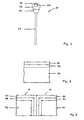
- Figure 1 shows a microphone 10, comprising a stem 12, non-conductive components 14, 16, 18 of the housing and a microphone capsule 20.
- the housing of the microphone 10 is composed of a first non-conductive component 14, a second non-conductive component 16 and a third non-conductive component 18.
- the first non-conductive component 14 and the second non-conductive component 16 work as a windshield, wherein the third non-conductive component works as a plop shield.
- the stem is made of metal, e.g. aluminium or copper.
- Figure 2 shows a cross section view of one of the non-conductive components 14, 16, 18 shown in figure 1 .
- the non-conductive components are made of plastic 30, wherein said non-conductive components are covered by a metal layer 32, wherein said metal layer is covered by a protective layer 34.
- the metal layer 32 and the protective layer 34 are in the outer face of the microphone.
- the metal layer 32 and the protective layer 34 is in the inside of the microphone and/or in the outer face of the microphone.
- the thicknesses of the metal layer and/or the protective layer is only a few micro meters (10-15 ⁇ m). The thickness itself does not matter as long as the complete surface is covered with material.
- the metal layer is added by known methods of sputtering, vacuum metallisation and/or lacquering.
- the protective layer is added by a spraying technique for paint.
- Figure 3 shows a cross section view of the contact point of the first non-conductive component 14 and the second non-conductive component 16 shown in figure 1 .
- the first non-conductive component 14 is made of plastic 30, wherein it is covered by a metal layer 32. Said metal layer is covered by a protective layer 34.
- the second non-conductive component 14 is also made of plastic 36, wherein it is covered by a metal layer 38.
- Said metal layer is covered by a protective layer 40.
- a protective layer 40 As material of the protective layer transparent and/or colored paint is used.
- the metal layer 32 of the first non-conductive component 14 and the metal layer 38 of the second non-conductive component 16 overlap partly, wherein the protective layer 34 of the first non-conductive component 14 and the protective layer 40 of the second non-conductive component 16 isolates the metal layers 32, 38 electrically.
- plastic all kind of plastic can be used, especially V2 type material or HB.
- the metal layer 32 of the first non-conductive component 14, the protective layers 34, 40 and the metal layer 38 of the second non-conductive component 16 works as a capacitor. Therefore for high frequencies the metal layers 32, 38 are electrically connected.
- the metal stem is connected to the system ground. This indirectly connects also the metal layer to the system ground.
- the metal stem and/or other parts of the microphone and the metal layer are electrically connected.
- the connection is capacitive with an isolator (protective layer).
- metal layers are made of or comprises aluminium and/or titanium and/or chrome.
- the actual shape of the overlap area shown in figure 3 differs depending on the component shape.
Landscapes
- Physics & Mathematics (AREA)
- Engineering & Computer Science (AREA)
- Acoustics & Sound (AREA)
- Signal Processing (AREA)
- Details Of Audible-Bandwidth Transducers (AREA)
- Shielding Devices Or Components To Electric Or Magnetic Fields (AREA)
- Laminated Bodies (AREA)
- Electrostatic, Electromagnetic, Magneto- Strictive, And Variable-Resistance Transducers (AREA)
- Piezo-Electric Transducers For Audible Bands (AREA)
- Measuring Pulse, Heart Rate, Blood Pressure Or Blood Flow (AREA)
Abstract
Description
- This invention relates to a microphone.
- GSM interference is a problem for a lot of electronic products. The commonly known solution is either a shielding by a metal cabinet or short circuit the high frequency signal by a capacitor. For a microphone both methods have their drawbacks, because metal shielding limits the modelling possibilities of the microphone. Placing a capacitor only works if it is very close to the semiconductor component in the microphone. Due to the high frequency of GSM systems or other wireless networks a capacitor is not effective enough.
-
US 2002/0106091 A1 discloses a microphone assembly casing, wherein said casing is a metallized non-conductive material, such as metal particle-coated plastics. -
WO 2004/017700 discloses an electromagnetically shielded article comprising a device that is surrounded with a visible light-transmissive film comprising a flexible support, an extensible visible light-transmissive metal layer and a visible light transmissive protective layer. - The present invention provides a microphone as defined in claim 1.
- The advantage of the microphone that is the object of the present invention is the following. The proposed shielding by a metal layer and the protection of the metal layer by a protective layer have the advantage, that such a shielding is cheap, because such a shielding can be placed on plastic in a low-cost way. Furthermore this keeps the modelling possibilities, for example the modelling possibilities of the housing of the microphone, equal to a not shielded microphone.
- The protective layer has the advantage that the metal layer is protected against mechanical and/or chemical influences.
- Aluminium is advantageous, because of its low cost, ease of sputtering and high adhesion to plastics. Furthermore aluminium has the advantage, that its conductivity is high. Chrome has the advantage, that it has an improved appearance and also a high corrosion resistance.
- Further advantages are derived from the features cited in the further dependent claims and in the description.
- An exemplary embodiment of the invention is shown in the drawing and described in further detail in the ensuing description.
- In the drawings:
-
Figure 1 shows a microphone, -
Figure 2 shows a cross section view, -
Figure 3 shows a cross section view. - In the following a microphone is described. The microphone comprises at least one non-conductive component, wherein at least one side of said non-conductive component is covered by a metal layer, wherein said metal layer is covered by a protective layer. The microphone comprises at least one first non-conductive component and at least one second non-conductive component, wherein said first non-conductive component and said second non-conductive component are arranged such that the metal layer of the first non-conductive component and the metal layer of the second non-conductive component overlap at least partly, wherein at least one protective layer isolates the metal layers electrically. The microphone is a component of a delegate unit of a conference system or a congress system.
- In the following an aluminium coating is added to all plastic components of a microphone housing for shielding purposes. This coating is also used to give the microphone an expensive look. It can also be covered with paint of any color, so that the microphone design can be adapted very easily to the environment. To avoid corrosion of the very thin aluminium layer an additional protective layer is placed. This protective layer isolates the different plastic components from each other. However because of the high frequency of interference signal and the very thin layers the combination works as a capacitor. Therefore, if the plastic components have some overlap to each other the electrical contact will be enough. The larger the overlap area the lower the frequency it can shield.
-
Figure 1 shows amicrophone 10, comprising astem 12,non-conductive components microphone capsule 20. The housing of themicrophone 10 is composed of a firstnon-conductive component 14, a secondnon-conductive component 16 and a thirdnon-conductive component 18. The firstnon-conductive component 14 and the secondnon-conductive component 16 work as a windshield, wherein the third non-conductive component works as a plop shield. The stem is made of metal, e.g. aluminium or copper. -
Figure 2 shows a cross section view of one of thenon-conductive components figure 1 . In the preferred embodiment the non-conductive components are made ofplastic 30, wherein said non-conductive components are covered by ametal layer 32, wherein said metal layer is covered by aprotective layer 34. Themetal layer 32 and theprotective layer 34 are in the outer face of the microphone. In another embodiment themetal layer 32 and theprotective layer 34 is in the inside of the microphone and/or in the outer face of the microphone. - The thicknesses of the metal layer and/or the protective layer is only a few micro meters (10-15µm). The thickness itself does not matter as long as the complete surface is covered with material.
- The metal layer is added by known methods of sputtering, vacuum metallisation and/or lacquering. The protective layer is added by a spraying technique for paint.
-
Figure 3 shows a cross section view of the contact point of the firstnon-conductive component 14 and the secondnon-conductive component 16 shown infigure 1 . The firstnon-conductive component 14 is made ofplastic 30, wherein it is covered by ametal layer 32. Said metal layer is covered by aprotective layer 34. The secondnon-conductive component 14 is also made ofplastic 36, wherein it is covered by ametal layer 38. - Said metal layer is covered by a
protective layer 40. As material of the protective layer transparent and/or colored paint is used. Themetal layer 32 of the firstnon-conductive component 14 and themetal layer 38 of the secondnon-conductive component 16 overlap partly, wherein theprotective layer 34 of the firstnon-conductive component 14 and theprotective layer 40 of the secondnon-conductive component 16 isolates themetal layers - As plastic all kind of plastic can be used, especially V2 type material or HB.
- The
metal layer 32 of the firstnon-conductive component 14, theprotective layers metal layer 38 of the secondnon-conductive component 16 works as a capacitor. Therefore for high frequencies themetal layers - The metal stem is connected to the system ground. This indirectly connects also the metal layer to the system ground.
- The metal stem and/or other parts of the microphone and the metal layer are electrically connected. The connection is capacitive with an isolator (protective layer).
- In the preferred embodiment the metal layers are made of or comprises aluminium and/or titanium and/or chrome.
- The actual shape of the overlap area shown in
figure 3 differs depending on the component shape.
Claims (5)
- Microphone comprising at least one non-conductive component, wherein at least one side of said non-conductive component is covered by a metal layer, wherein said metal layer is covered by a protective layer, characterised by at least one first non-conductive component and at least one second non-conductive component, wherein said first non-conductive component and said second non-conductive component are arranged such that the metal layer of the first non-conductive component and the metal layer of the second non-conductive component overlap at least partly, wherein at least one protective layer isolates the metal layers electrically.
- Microphone according to claim 1, characterised in that said microphone comprises a housing, wherein said housing is composed of the non-conductive components.
- Microphone according to one of the preceding claims, characterised in that said non-conductive component is made of plastic.
- Microphone according to claim 1, characterised in that said metal layer comprises aluminium.
- Microphone according to one of the preceding claims, characterised in that said metal layer comprises titanium and/or chrome.
Priority Applications (7)
| Application Number | Priority Date | Filing Date | Title |
|---|---|---|---|
| AT05100488T ATE492126T1 (en) | 2005-01-26 | 2005-01-26 | MICROPHONE |
| EP05100488A EP1596628B1 (en) | 2005-01-26 | 2005-01-26 | Microphone |
| ES05100488T ES2358196T3 (en) | 2005-01-26 | 2005-01-26 | MICROPHONE. |
| DE602005025278T DE602005025278D1 (en) | 2005-01-26 | 2005-01-26 | microphone |
| US11/326,054 US8014546B2 (en) | 2005-01-26 | 2006-01-05 | EMI shielding for a microphone |
| CN200610006238.0A CN1812630B (en) | 2005-01-26 | 2006-01-23 | microphone |
| JP2006016466A JP5038628B2 (en) | 2005-01-26 | 2006-01-25 | Microphone |
Applications Claiming Priority (1)
| Application Number | Priority Date | Filing Date | Title |
|---|---|---|---|
| EP05100488A EP1596628B1 (en) | 2005-01-26 | 2005-01-26 | Microphone |
Publications (2)
| Publication Number | Publication Date |
|---|---|
| EP1596628A1 EP1596628A1 (en) | 2005-11-16 |
| EP1596628B1 true EP1596628B1 (en) | 2010-12-15 |
Family
ID=34938576
Family Applications (1)
| Application Number | Title | Priority Date | Filing Date |
|---|---|---|---|
| EP05100488A Expired - Lifetime EP1596628B1 (en) | 2005-01-26 | 2005-01-26 | Microphone |
Country Status (7)
| Country | Link |
|---|---|
| US (1) | US8014546B2 (en) |
| EP (1) | EP1596628B1 (en) |
| JP (1) | JP5038628B2 (en) |
| CN (1) | CN1812630B (en) |
| AT (1) | ATE492126T1 (en) |
| DE (1) | DE602005025278D1 (en) |
| ES (1) | ES2358196T3 (en) |
Families Citing this family (2)
| Publication number | Priority date | Publication date | Assignee | Title |
|---|---|---|---|---|
| CN101502128A (en) | 2006-08-03 | 2009-08-05 | 日本电气株式会社 | Portable terminal device and housing for portable terminal device |
| US20250338050A1 (en) * | 2024-04-25 | 2025-10-30 | Shure Acquisition Holdings, Inc. | Electromagnetic shielding for microphone |
Family Cites Families (10)
| Publication number | Priority date | Publication date | Assignee | Title |
|---|---|---|---|---|
| JPS5671688U (en) * | 1979-11-05 | 1981-06-12 | ||
| US4993072A (en) | 1989-02-24 | 1991-02-12 | Lectret S.A. | Shielded electret transducer and method of making the same |
| DE4343703C1 (en) * | 1993-12-21 | 1995-01-05 | Siemens Audiologische Technik | Hearing aid which can be worn on the head |
| JP3194185B2 (en) * | 1997-10-13 | 2001-07-30 | 株式会社エツミ光学 | Electromagnetic wave shield molded product |
| US6097613A (en) * | 1997-12-12 | 2000-08-01 | Nortel Networks Limited | Assemblies of electronic devices and flexible containers therefor |
| EP1067819B1 (en) * | 1999-07-08 | 2004-06-09 | Matsushita Electric Industrial Co., Ltd. | Condenser microphone apparatus and its connecting apparatus |
| US6741709B2 (en) * | 2000-12-20 | 2004-05-25 | Shure Incorporated | Condenser microphone assembly |
| US20020106091A1 (en) * | 2001-02-02 | 2002-08-08 | Furst Claus Erdmann | Microphone unit with internal A/D converter |
| JP2004007330A (en) * | 2002-05-31 | 2004-01-08 | Goro Yamauchi | Water-proof and wind-proof electrostatic shielding apparatus for microphone |
| US6818291B2 (en) * | 2002-08-17 | 2004-11-16 | 3M Innovative Properties Company | Durable transparent EMI shielding film |
-
2005
- 2005-01-26 EP EP05100488A patent/EP1596628B1/en not_active Expired - Lifetime
- 2005-01-26 DE DE602005025278T patent/DE602005025278D1/en not_active Expired - Lifetime
- 2005-01-26 ES ES05100488T patent/ES2358196T3/en not_active Expired - Lifetime
- 2005-01-26 AT AT05100488T patent/ATE492126T1/en not_active IP Right Cessation
-
2006
- 2006-01-05 US US11/326,054 patent/US8014546B2/en not_active Expired - Fee Related
- 2006-01-23 CN CN200610006238.0A patent/CN1812630B/en not_active Expired - Fee Related
- 2006-01-25 JP JP2006016466A patent/JP5038628B2/en not_active Expired - Fee Related
Also Published As
| Publication number | Publication date |
|---|---|
| US8014546B2 (en) | 2011-09-06 |
| EP1596628A1 (en) | 2005-11-16 |
| JP2006211666A (en) | 2006-08-10 |
| CN1812630B (en) | 2012-04-18 |
| ES2358196T3 (en) | 2011-05-06 |
| US20060162996A1 (en) | 2006-07-27 |
| CN1812630A (en) | 2006-08-02 |
| JP5038628B2 (en) | 2012-10-03 |
| DE602005025278D1 (en) | 2011-01-27 |
| ATE492126T1 (en) | 2011-01-15 |
Similar Documents
| Publication | Publication Date | Title |
|---|---|---|
| US10524372B2 (en) | Enclosure with metal interior surface layer | |
| US11355453B2 (en) | Electronic assembly, electronic apparatus including the same and method for fabricating electronic assembly | |
| US5867371A (en) | Cover member for sealed circuit board assembly | |
| WO2007098325A1 (en) | Printable controls for a window assembly | |
| US20100294641A1 (en) | Sanitary Fitting With an Electrical Operating Device, Which has at Least One Capacitive Sensor | |
| US20120098755A1 (en) | Touch module | |
| KR100618085B1 (en) | EM and ESD shield for components on board of electronic products and manufacturing method thereof | |
| US12027038B2 (en) | Visible components with functional coating | |
| JP3336160B2 (en) | Protective device against electrostatic discharge and broadcast interference | |
| JPH1056285A5 (en) | ||
| KR20170026982A (en) | Sensor for detecting fingerprint and method for manufacturing the same | |
| EP3174372B1 (en) | Electrostatic surge prevention structure | |
| WO2004086202B1 (en) | A security housing for a circuit | |
| US20060162996A1 (en) | Microphone | |
| US20120262889A1 (en) | Electromagnetic shielding cover | |
| KR20030076470A (en) | An apparutus and method for EMI and ESD shielding using plastic can in borad of electronic equipment | |
| CN101083896A (en) | A method of forming an electromagnetic wave interference shielding film on a non-conductive material and its structure | |
| WO2003032702A1 (en) | Method for shielding electromagnetic wave and electromagnetic wave shielding window, production apparatus equipped with electromagnetic wave shielding window, transporting apparatus equipped with electromagnetic wave shielding window, and building structure equipped with electromagnetic wave shielding wind | |
| CN105373245A (en) | Cover plate and electronic device | |
| CN219981431U (en) | Sensor packaging structure and electronic equipment | |
| KR20130002694U (en) | Multifunction touch panel | |
| JP6817650B1 (en) | Electronics | |
| JP2014089737A (en) | Molding member and translucent type input device | |
| CN102378565A (en) | Cover body and electronic device using same |
Legal Events
| Date | Code | Title | Description |
|---|---|---|---|
| PUAI | Public reference made under article 153(3) epc to a published international application that has entered the european phase |
Free format text: ORIGINAL CODE: 0009012 |
|
| AK | Designated contracting states |
Kind code of ref document: A1 Designated state(s): AT BE BG CH CY CZ DE DK EE ES FI FR GB GR HU IE IS IT LI LT LU MC NL PL PT RO SE SI SK TR |
|
| AX | Request for extension of the european patent |
Extension state: AL BA HR LV MK YU |
|
| RIN1 | Information on inventor provided before grant (corrected) |
Inventor name: SMAAK, MARC Inventor name: KAS, MARTIEN Inventor name: HERMANS, AD Inventor name: LURVINK, RENE |
|
| 17P | Request for examination filed |
Effective date: 20060516 |
|
| AKX | Designation fees paid |
Designated state(s): AT BE BG CH CY CZ DE DK EE ES FI FR GB GR HU IE IS IT LI LT LU MC NL PL PT RO SE SI SK TR |
|
| 17Q | First examination report despatched |
Effective date: 20070613 |
|
| GRAP | Despatch of communication of intention to grant a patent |
Free format text: ORIGINAL CODE: EPIDOSNIGR1 |
|
| GRAS | Grant fee paid |
Free format text: ORIGINAL CODE: EPIDOSNIGR3 |
|
| GRAA | (expected) grant |
Free format text: ORIGINAL CODE: 0009210 |
|
| AK | Designated contracting states |
Kind code of ref document: B1 Designated state(s): AT BE BG CH CY CZ DE DK EE ES FI FR GB GR HU IE IS IT LI LT LU MC NL PL PT RO SE SI SK TR |
|
| REG | Reference to a national code |
Ref country code: GB Ref legal event code: FG4D Ref country code: CH Ref legal event code: EP |
|
| REG | Reference to a national code |
Ref country code: IE Ref legal event code: FG4D |
|
| REF | Corresponds to: |
Ref document number: 602005025278 Country of ref document: DE Date of ref document: 20110127 Kind code of ref document: P |
|
| REG | Reference to a national code |
Ref country code: NL Ref legal event code: T3 |
|
| PG25 | Lapsed in a contracting state [announced via postgrant information from national office to epo] |
Ref country code: LT Free format text: LAPSE BECAUSE OF FAILURE TO SUBMIT A TRANSLATION OF THE DESCRIPTION OR TO PAY THE FEE WITHIN THE PRESCRIBED TIME-LIMIT Effective date: 20101215 |
|
| REG | Reference to a national code |
Ref country code: ES Ref legal event code: FG2A Ref document number: 2358196 Country of ref document: ES Kind code of ref document: T3 Effective date: 20110425 |
|
| LTIE | Lt: invalidation of european patent or patent extension |
Effective date: 20101215 |
|
| PG25 | Lapsed in a contracting state [announced via postgrant information from national office to epo] |
Ref country code: FI Free format text: LAPSE BECAUSE OF FAILURE TO SUBMIT A TRANSLATION OF THE DESCRIPTION OR TO PAY THE FEE WITHIN THE PRESCRIBED TIME-LIMIT Effective date: 20101215 Ref country code: SE Free format text: LAPSE BECAUSE OF FAILURE TO SUBMIT A TRANSLATION OF THE DESCRIPTION OR TO PAY THE FEE WITHIN THE PRESCRIBED TIME-LIMIT Effective date: 20101215 Ref country code: SI Free format text: LAPSE BECAUSE OF FAILURE TO SUBMIT A TRANSLATION OF THE DESCRIPTION OR TO PAY THE FEE WITHIN THE PRESCRIBED TIME-LIMIT Effective date: 20101215 Ref country code: BG Free format text: LAPSE BECAUSE OF FAILURE TO SUBMIT A TRANSLATION OF THE DESCRIPTION OR TO PAY THE FEE WITHIN THE PRESCRIBED TIME-LIMIT Effective date: 20110315 Ref country code: AT Free format text: LAPSE BECAUSE OF FAILURE TO SUBMIT A TRANSLATION OF THE DESCRIPTION OR TO PAY THE FEE WITHIN THE PRESCRIBED TIME-LIMIT Effective date: 20101215 Ref country code: CY Free format text: LAPSE BECAUSE OF FAILURE TO SUBMIT A TRANSLATION OF THE DESCRIPTION OR TO PAY THE FEE WITHIN THE PRESCRIBED TIME-LIMIT Effective date: 20101215 |
|
| PG25 | Lapsed in a contracting state [announced via postgrant information from national office to epo] |
Ref country code: BE Free format text: LAPSE BECAUSE OF FAILURE TO SUBMIT A TRANSLATION OF THE DESCRIPTION OR TO PAY THE FEE WITHIN THE PRESCRIBED TIME-LIMIT Effective date: 20101215 Ref country code: GR Free format text: LAPSE BECAUSE OF FAILURE TO SUBMIT A TRANSLATION OF THE DESCRIPTION OR TO PAY THE FEE WITHIN THE PRESCRIBED TIME-LIMIT Effective date: 20110316 Ref country code: IS Free format text: LAPSE BECAUSE OF FAILURE TO SUBMIT A TRANSLATION OF THE DESCRIPTION OR TO PAY THE FEE WITHIN THE PRESCRIBED TIME-LIMIT Effective date: 20110415 Ref country code: PT Free format text: LAPSE BECAUSE OF FAILURE TO SUBMIT A TRANSLATION OF THE DESCRIPTION OR TO PAY THE FEE WITHIN THE PRESCRIBED TIME-LIMIT Effective date: 20110415 Ref country code: CZ Free format text: LAPSE BECAUSE OF FAILURE TO SUBMIT A TRANSLATION OF THE DESCRIPTION OR TO PAY THE FEE WITHIN THE PRESCRIBED TIME-LIMIT Effective date: 20101215 Ref country code: EE Free format text: LAPSE BECAUSE OF FAILURE TO SUBMIT A TRANSLATION OF THE DESCRIPTION OR TO PAY THE FEE WITHIN THE PRESCRIBED TIME-LIMIT Effective date: 20101215 |
|
| PG25 | Lapsed in a contracting state [announced via postgrant information from national office to epo] |
Ref country code: SK Free format text: LAPSE BECAUSE OF FAILURE TO SUBMIT A TRANSLATION OF THE DESCRIPTION OR TO PAY THE FEE WITHIN THE PRESCRIBED TIME-LIMIT Effective date: 20101215 Ref country code: PL Free format text: LAPSE BECAUSE OF FAILURE TO SUBMIT A TRANSLATION OF THE DESCRIPTION OR TO PAY THE FEE WITHIN THE PRESCRIBED TIME-LIMIT Effective date: 20101215 Ref country code: MC Free format text: LAPSE BECAUSE OF NON-PAYMENT OF DUE FEES Effective date: 20110131 Ref country code: RO Free format text: LAPSE BECAUSE OF FAILURE TO SUBMIT A TRANSLATION OF THE DESCRIPTION OR TO PAY THE FEE WITHIN THE PRESCRIBED TIME-LIMIT Effective date: 20101215 |
|
| REG | Reference to a national code |
Ref country code: CH Ref legal event code: PL |
|
| PLBE | No opposition filed within time limit |
Free format text: ORIGINAL CODE: 0009261 |
|
| STAA | Information on the status of an ep patent application or granted ep patent |
Free format text: STATUS: NO OPPOSITION FILED WITHIN TIME LIMIT |
|
| REG | Reference to a national code |
Ref country code: IE Ref legal event code: MM4A |
|
| PG25 | Lapsed in a contracting state [announced via postgrant information from national office to epo] |
Ref country code: DK Free format text: LAPSE BECAUSE OF FAILURE TO SUBMIT A TRANSLATION OF THE DESCRIPTION OR TO PAY THE FEE WITHIN THE PRESCRIBED TIME-LIMIT Effective date: 20101215 Ref country code: CH Free format text: LAPSE BECAUSE OF NON-PAYMENT OF DUE FEES Effective date: 20110131 Ref country code: LI Free format text: LAPSE BECAUSE OF NON-PAYMENT OF DUE FEES Effective date: 20110131 |
|
| 26N | No opposition filed |
Effective date: 20110916 |
|
| REG | Reference to a national code |
Ref country code: DE Ref legal event code: R097 Ref document number: 602005025278 Country of ref document: DE Effective date: 20110916 |
|
| PG25 | Lapsed in a contracting state [announced via postgrant information from national office to epo] |
Ref country code: IE Free format text: LAPSE BECAUSE OF NON-PAYMENT OF DUE FEES Effective date: 20110126 |
|
| PG25 | Lapsed in a contracting state [announced via postgrant information from national office to epo] |
Ref country code: LU Free format text: LAPSE BECAUSE OF NON-PAYMENT OF DUE FEES Effective date: 20110126 |
|
| PG25 | Lapsed in a contracting state [announced via postgrant information from national office to epo] |
Ref country code: TR Free format text: LAPSE BECAUSE OF FAILURE TO SUBMIT A TRANSLATION OF THE DESCRIPTION OR TO PAY THE FEE WITHIN THE PRESCRIBED TIME-LIMIT Effective date: 20101215 |
|
| PG25 | Lapsed in a contracting state [announced via postgrant information from national office to epo] |
Ref country code: HU Free format text: LAPSE BECAUSE OF FAILURE TO SUBMIT A TRANSLATION OF THE DESCRIPTION OR TO PAY THE FEE WITHIN THE PRESCRIBED TIME-LIMIT Effective date: 20101215 |
|
| REG | Reference to a national code |
Ref country code: FR Ref legal event code: PLFP Year of fee payment: 12 |
|
| REG | Reference to a national code |
Ref country code: FR Ref legal event code: PLFP Year of fee payment: 13 |
|
| REG | Reference to a national code |
Ref country code: FR Ref legal event code: PLFP Year of fee payment: 14 |
|
| PGFP | Annual fee paid to national office [announced via postgrant information from national office to epo] |
Ref country code: GB Payment date: 20220125 Year of fee payment: 18 |
|
| PGFP | Annual fee paid to national office [announced via postgrant information from national office to epo] |
Ref country code: NL Payment date: 20220120 Year of fee payment: 18 Ref country code: IT Payment date: 20220124 Year of fee payment: 18 Ref country code: FR Payment date: 20220120 Year of fee payment: 18 Ref country code: ES Payment date: 20220216 Year of fee payment: 18 |
|
| REG | Reference to a national code |
Ref country code: NL Ref legal event code: MM Effective date: 20230201 |
|
| GBPC | Gb: european patent ceased through non-payment of renewal fee |
Effective date: 20230126 |
|
| PG25 | Lapsed in a contracting state [announced via postgrant information from national office to epo] |
Ref country code: NL Free format text: LAPSE BECAUSE OF NON-PAYMENT OF DUE FEES Effective date: 20230201 Ref country code: GB Free format text: LAPSE BECAUSE OF NON-PAYMENT OF DUE FEES Effective date: 20230126 |
|
| PG25 | Lapsed in a contracting state [announced via postgrant information from national office to epo] |
Ref country code: FR Free format text: LAPSE BECAUSE OF NON-PAYMENT OF DUE FEES Effective date: 20230131 |
|
| PG25 | Lapsed in a contracting state [announced via postgrant information from national office to epo] |
Ref country code: IT Free format text: LAPSE BECAUSE OF NON-PAYMENT OF DUE FEES Effective date: 20230126 |
|
| REG | Reference to a national code |
Ref country code: ES Ref legal event code: FD2A Effective date: 20240402 |
|
| PG25 | Lapsed in a contracting state [announced via postgrant information from national office to epo] |
Ref country code: ES Free format text: LAPSE BECAUSE OF NON-PAYMENT OF DUE FEES Effective date: 20230127 |
|
| PG25 | Lapsed in a contracting state [announced via postgrant information from national office to epo] |
Ref country code: ES Free format text: LAPSE BECAUSE OF NON-PAYMENT OF DUE FEES Effective date: 20230127 |
|
| PGFP | Annual fee paid to national office [announced via postgrant information from national office to epo] |
Ref country code: DE Payment date: 20240322 Year of fee payment: 20 |
|
| REG | Reference to a national code |
Ref country code: DE Ref legal event code: R071 Ref document number: 602005025278 Country of ref document: DE |