EP1596234A1 - Coated optical fiber and coated optical fiber with connector - Google Patents
Coated optical fiber and coated optical fiber with connector Download PDFInfo
- Publication number
- EP1596234A1 EP1596234A1 EP04712701A EP04712701A EP1596234A1 EP 1596234 A1 EP1596234 A1 EP 1596234A1 EP 04712701 A EP04712701 A EP 04712701A EP 04712701 A EP04712701 A EP 04712701A EP 1596234 A1 EP1596234 A1 EP 1596234A1
- Authority
- EP
- European Patent Office
- Prior art keywords
- optical fiber
- buffered optical
- layer
- coating layer
- polymer
- Prior art date
- Legal status (The legal status is an assumption and is not a legal conclusion. Google has not performed a legal analysis and makes no representation as to the accuracy of the status listed.)
- Withdrawn
Links
- 239000013307 optical fiber Substances 0.000 title claims abstract description 210
- 239000011247 coating layer Substances 0.000 claims abstract description 120
- 239000003365 glass fiber Substances 0.000 claims abstract description 80
- 239000011342 resin composition Substances 0.000 claims abstract description 60
- IJGRMHOSHXDMSA-UHFFFAOYSA-N Atomic nitrogen Chemical compound N#N IJGRMHOSHXDMSA-UHFFFAOYSA-N 0.000 claims abstract description 58
- 239000000463 material Substances 0.000 claims abstract description 49
- 230000005540 biological transmission Effects 0.000 claims abstract description 40
- RNFJDJUURJAICM-UHFFFAOYSA-N 2,2,4,4,6,6-hexaphenoxy-1,3,5-triaza-2$l^{5},4$l^{5},6$l^{5}-triphosphacyclohexa-1,3,5-triene Chemical compound N=1P(OC=2C=CC=CC=2)(OC=2C=CC=CC=2)=NP(OC=2C=CC=CC=2)(OC=2C=CC=CC=2)=NP=1(OC=1C=CC=CC=1)OC1=CC=CC=C1 RNFJDJUURJAICM-UHFFFAOYSA-N 0.000 claims abstract description 32
- 239000003063 flame retardant Substances 0.000 claims abstract description 32
- 229910052757 nitrogen Inorganic materials 0.000 claims abstract description 29
- 229910000000 metal hydroxide Inorganic materials 0.000 claims abstract description 22
- 150000004692 metal hydroxides Chemical class 0.000 claims abstract description 22
- 229920005601 base polymer Polymers 0.000 claims abstract description 20
- 230000002093 peripheral effect Effects 0.000 claims abstract description 16
- 239000010410 layer Substances 0.000 claims description 182
- 229920005989 resin Polymers 0.000 claims description 79
- 239000011347 resin Substances 0.000 claims description 79
- 229920000642 polymer Polymers 0.000 claims description 76
- 239000004793 Polystyrene Substances 0.000 claims description 39
- 239000011248 coating agent Substances 0.000 claims description 33
- 238000000576 coating method Methods 0.000 claims description 33
- 229920002223 polystyrene Polymers 0.000 claims description 33
- 229920001971 elastomer Polymers 0.000 claims description 25
- 238000012360 testing method Methods 0.000 claims description 22
- 239000000203 mixture Substances 0.000 claims description 21
- 239000000806 elastomer Substances 0.000 claims description 20
- 229920001169 thermoplastic Polymers 0.000 claims description 17
- 229920001955 polyphenylene ether Polymers 0.000 claims description 16
- 229920000098 polyolefin Polymers 0.000 claims description 9
- 239000011796 hollow space material Substances 0.000 claims description 8
- 238000012986 modification Methods 0.000 claims description 4
- 239000002253 acid Substances 0.000 claims description 2
- 230000004048 modification Effects 0.000 claims description 2
- 230000003287 optical effect Effects 0.000 abstract description 21
- 230000007613 environmental effect Effects 0.000 abstract description 4
- 238000000034 method Methods 0.000 description 17
- 238000004519 manufacturing process Methods 0.000 description 12
- 239000012212 insulator Substances 0.000 description 10
- -1 phosphorus compound Chemical class 0.000 description 8
- NIXOWILDQLNWCW-UHFFFAOYSA-M Acrylate Chemical compound [O-]C(=O)C=C NIXOWILDQLNWCW-UHFFFAOYSA-M 0.000 description 7
- 239000000654 additive Substances 0.000 description 7
- 239000003795 chemical substances by application Substances 0.000 description 7
- 230000000052 comparative effect Effects 0.000 description 7
- UHESRSKEBRADOO-UHFFFAOYSA-N ethyl carbamate;prop-2-enoic acid Chemical compound OC(=O)C=C.CCOC(N)=O UHESRSKEBRADOO-UHFFFAOYSA-N 0.000 description 7
- 239000003112 inhibitor Substances 0.000 description 7
- 230000003647 oxidation Effects 0.000 description 7
- 238000007254 oxidation reaction Methods 0.000 description 7
- 238000001125 extrusion Methods 0.000 description 6
- NINIDFKCEFEMDL-UHFFFAOYSA-N Sulfur Chemical compound [S] NINIDFKCEFEMDL-UHFFFAOYSA-N 0.000 description 5
- 239000004611 light stabiliser Substances 0.000 description 5
- 239000005060 rubber Substances 0.000 description 5
- 229910052717 sulfur Inorganic materials 0.000 description 5
- 239000011593 sulfur Substances 0.000 description 5
- LYCAIKOWRPUZTN-UHFFFAOYSA-N Ethylene glycol Chemical compound OCCO LYCAIKOWRPUZTN-UHFFFAOYSA-N 0.000 description 4
- VYPSYNLAJGMNEJ-UHFFFAOYSA-N Silicium dioxide Chemical compound O=[Si]=O VYPSYNLAJGMNEJ-UHFFFAOYSA-N 0.000 description 4
- 150000001875 compounds Chemical class 0.000 description 4
- 230000001678 irradiating effect Effects 0.000 description 4
- 238000002156 mixing Methods 0.000 description 4
- 239000000178 monomer Substances 0.000 description 4
- 239000002341 toxic gas Substances 0.000 description 4
- 239000005062 Polybutadiene Substances 0.000 description 3
- XBDQKXXYIPTUBI-UHFFFAOYSA-M Propionate Chemical compound CCC([O-])=O XBDQKXXYIPTUBI-UHFFFAOYSA-M 0.000 description 3
- 238000007792 addition Methods 0.000 description 3
- 230000000996 additive effect Effects 0.000 description 3
- IISBACLAFKSPIT-UHFFFAOYSA-N bisphenol A Chemical compound C=1C=C(O)C=CC=1C(C)(C)C1=CC=C(O)C=C1 IISBACLAFKSPIT-UHFFFAOYSA-N 0.000 description 3
- 239000003086 colorant Substances 0.000 description 3
- 238000004891 communication Methods 0.000 description 3
- 239000004020 conductor Substances 0.000 description 3
- 239000000470 constituent Substances 0.000 description 3
- 239000007789 gas Substances 0.000 description 3
- 239000002655 kraft paper Substances 0.000 description 3
- 239000000314 lubricant Substances 0.000 description 3
- VNWKTOKETHGBQD-UHFFFAOYSA-N methane Natural products C VNWKTOKETHGBQD-UHFFFAOYSA-N 0.000 description 3
- 229920002857 polybutadiene Polymers 0.000 description 3
- 229920001296 polysiloxane Polymers 0.000 description 3
- 230000035882 stress Effects 0.000 description 3
- 229920000468 styrene butadiene styrene block copolymer Polymers 0.000 description 3
- JWYVGKFDLWWQJX-UHFFFAOYSA-N 1-ethenylazepan-2-one Chemical compound C=CN1CCCCCC1=O JWYVGKFDLWWQJX-UHFFFAOYSA-N 0.000 description 2
- 239000004925 Acrylic resin Substances 0.000 description 2
- 229920000742 Cotton Polymers 0.000 description 2
- 239000004593 Epoxy Substances 0.000 description 2
- 229920000181 Ethylene propylene rubber Polymers 0.000 description 2
- RRHGJUQNOFWUDK-UHFFFAOYSA-N Isoprene Chemical compound CC(=C)C=C RRHGJUQNOFWUDK-UHFFFAOYSA-N 0.000 description 2
- 239000004721 Polyphenylene oxide Substances 0.000 description 2
- 150000001412 amines Chemical class 0.000 description 2
- 239000003963 antioxidant agent Substances 0.000 description 2
- 230000003078 antioxidant effect Effects 0.000 description 2
- 229920001400 block copolymer Polymers 0.000 description 2
- 239000000498 cooling water Substances 0.000 description 2
- 238000005520 cutting process Methods 0.000 description 2
- 230000002950 deficient Effects 0.000 description 2
- PODOEQVNFJSWIK-UHFFFAOYSA-N diphenylphosphoryl-(2,4,6-trimethoxyphenyl)methanone Chemical compound COC1=CC(OC)=CC(OC)=C1C(=O)P(=O)(C=1C=CC=CC=1)C1=CC=CC=C1 PODOEQVNFJSWIK-UHFFFAOYSA-N 0.000 description 2
- 125000005843 halogen group Chemical group 0.000 description 2
- 238000010438 heat treatment Methods 0.000 description 2
- 229920005669 high impact polystyrene Polymers 0.000 description 2
- 239000004797 high-impact polystyrene Substances 0.000 description 2
- WGCNASOHLSPBMP-UHFFFAOYSA-N hydroxyacetaldehyde Natural products OCC=O WGCNASOHLSPBMP-UHFFFAOYSA-N 0.000 description 2
- 229910044991 metal oxide Inorganic materials 0.000 description 2
- 239000011574 phosphorus Substances 0.000 description 2
- 229910052698 phosphorus Inorganic materials 0.000 description 2
- 230000000704 physical effect Effects 0.000 description 2
- 239000000049 pigment Substances 0.000 description 2
- 229920006380 polyphenylene oxide Polymers 0.000 description 2
- 229920000346 polystyrene-polyisoprene block-polystyrene Polymers 0.000 description 2
- 229920002545 silicone oil Polymers 0.000 description 2
- 229920002050 silicone resin Polymers 0.000 description 2
- 239000007787 solid Substances 0.000 description 2
- 229920006132 styrene block copolymer Polymers 0.000 description 2
- 239000000126 substance Substances 0.000 description 2
- DVKJHBMWWAPEIU-UHFFFAOYSA-N toluene 2,4-diisocyanate Chemical compound CC1=CC=C(N=C=O)C=C1N=C=O DVKJHBMWWAPEIU-UHFFFAOYSA-N 0.000 description 2
- QNODIIQQMGDSEF-UHFFFAOYSA-N (1-hydroxycyclohexyl)-phenylmethanone Chemical compound C=1C=CC=CC=1C(=O)C1(O)CCCCC1 QNODIIQQMGDSEF-UHFFFAOYSA-N 0.000 description 1
- PJAKWOZHTFWTNF-UHFFFAOYSA-N (2-nonylphenyl) prop-2-enoate Chemical compound CCCCCCCCCC1=CC=CC=C1OC(=O)C=C PJAKWOZHTFWTNF-UHFFFAOYSA-N 0.000 description 1
- PSGCQDPCAWOCSH-UHFFFAOYSA-N (4,7,7-trimethyl-3-bicyclo[2.2.1]heptanyl) prop-2-enoate Chemical compound C1CC2(C)C(OC(=O)C=C)CC1C2(C)C PSGCQDPCAWOCSH-UHFFFAOYSA-N 0.000 description 1
- OHVLMTFVQDZYHP-UHFFFAOYSA-N 1-(2,4,6,7-tetrahydrotriazolo[4,5-c]pyridin-5-yl)-2-[4-[2-[[3-(trifluoromethoxy)phenyl]methylamino]pyrimidin-5-yl]piperazin-1-yl]ethanone Chemical compound N1N=NC=2CN(CCC=21)C(CN1CCN(CC1)C=1C=NC(=NC=1)NCC1=CC(=CC=C1)OC(F)(F)F)=O OHVLMTFVQDZYHP-UHFFFAOYSA-N 0.000 description 1
- WZFUQSJFWNHZHM-UHFFFAOYSA-N 2-[4-[2-(2,3-dihydro-1H-inden-2-ylamino)pyrimidin-5-yl]piperazin-1-yl]-1-(2,4,6,7-tetrahydrotriazolo[4,5-c]pyridin-5-yl)ethanone Chemical compound C1C(CC2=CC=CC=C12)NC1=NC=C(C=N1)N1CCN(CC1)CC(=O)N1CC2=C(CC1)NN=N2 WZFUQSJFWNHZHM-UHFFFAOYSA-N 0.000 description 1
- NLGDWWCZQDIASO-UHFFFAOYSA-N 2-hydroxy-1-(7-oxabicyclo[4.1.0]hepta-1,3,5-trien-2-yl)-2-phenylethanone Chemical compound OC(C(=O)c1cccc2Oc12)c1ccccc1 NLGDWWCZQDIASO-UHFFFAOYSA-N 0.000 description 1
- OMIGHNLMNHATMP-UHFFFAOYSA-N 2-hydroxyethyl prop-2-enoate Chemical compound OCCOC(=O)C=C OMIGHNLMNHATMP-UHFFFAOYSA-N 0.000 description 1
- UUEWCQRISZBELL-UHFFFAOYSA-N 3-trimethoxysilylpropane-1-thiol Chemical compound CO[Si](OC)(OC)CCCS UUEWCQRISZBELL-UHFFFAOYSA-N 0.000 description 1
- 229930185605 Bisphenol Natural products 0.000 description 1
- GAWIXWVDTYZWAW-UHFFFAOYSA-N C[CH]O Chemical group C[CH]O GAWIXWVDTYZWAW-UHFFFAOYSA-N 0.000 description 1
- 239000005977 Ethylene Substances 0.000 description 1
- 239000004606 Fillers/Extenders Substances 0.000 description 1
- 239000005058 Isophorone diisocyanate Substances 0.000 description 1
- OAICVXFJPJFONN-UHFFFAOYSA-N Phosphorus Chemical compound [P] OAICVXFJPJFONN-UHFFFAOYSA-N 0.000 description 1
- 239000004952 Polyamide Substances 0.000 description 1
- OFOBLEOULBTSOW-UHFFFAOYSA-N Propanedioic acid Natural products OC(=O)CC(O)=O OFOBLEOULBTSOW-UHFFFAOYSA-N 0.000 description 1
- XUIMIQQOPSSXEZ-UHFFFAOYSA-N Silicon Chemical compound [Si] XUIMIQQOPSSXEZ-UHFFFAOYSA-N 0.000 description 1
- ZJCCRDAZUWHFQH-UHFFFAOYSA-N Trimethylolpropane Chemical compound CCC(CO)(CO)CO ZJCCRDAZUWHFQH-UHFFFAOYSA-N 0.000 description 1
- 239000007983 Tris buffer Substances 0.000 description 1
- BZHJMEDXRYGGRV-UHFFFAOYSA-N Vinyl chloride Chemical compound ClC=C BZHJMEDXRYGGRV-UHFFFAOYSA-N 0.000 description 1
- 239000000853 adhesive Substances 0.000 description 1
- WNROFYMDJYEPJX-UHFFFAOYSA-K aluminium hydroxide Chemical compound [OH-].[OH-].[OH-].[Al+3] WNROFYMDJYEPJX-UHFFFAOYSA-K 0.000 description 1
- 238000000137 annealing Methods 0.000 description 1
- RWCCWEUUXYIKHB-UHFFFAOYSA-N benzophenone Chemical compound C=1C=CC=CC=1C(=O)C1=CC=CC=C1 RWCCWEUUXYIKHB-UHFFFAOYSA-N 0.000 description 1
- 239000012965 benzophenone Substances 0.000 description 1
- 230000015556 catabolic process Effects 0.000 description 1
- 238000002485 combustion reaction Methods 0.000 description 1
- 239000002131 composite material Substances 0.000 description 1
- 238000013329 compounding Methods 0.000 description 1
- 230000008602 contraction Effects 0.000 description 1
- 229920001577 copolymer Polymers 0.000 description 1
- 238000004132 cross linking Methods 0.000 description 1
- 239000003431 cross linking reagent Substances 0.000 description 1
- 229920006038 crystalline resin Polymers 0.000 description 1
- 238000006731 degradation reaction Methods 0.000 description 1
- 230000006866 deterioration Effects 0.000 description 1
- 150000001993 dienes Chemical class 0.000 description 1
- 239000003085 diluting agent Substances 0.000 description 1
- 239000002270 dispersing agent Substances 0.000 description 1
- 230000000694 effects Effects 0.000 description 1
- 150000002148 esters Chemical class 0.000 description 1
- 238000011156 evaluation Methods 0.000 description 1
- 230000001747 exhibiting effect Effects 0.000 description 1
- 230000002349 favourable effect Effects 0.000 description 1
- 230000009970 fire resistant effect Effects 0.000 description 1
- GJIDOLBZYSCZRX-UHFFFAOYSA-N hydroxymethyl prop-2-enoate Chemical compound OCOC(=O)C=C GJIDOLBZYSCZRX-UHFFFAOYSA-N 0.000 description 1
- 230000001969 hypertrophic effect Effects 0.000 description 1
- 229910000765 intermetallic Inorganic materials 0.000 description 1
- ZFSLODLOARCGLH-UHFFFAOYSA-N isocyanuric acid Chemical compound OC1=NC(O)=NC(O)=N1 ZFSLODLOARCGLH-UHFFFAOYSA-N 0.000 description 1
- NIMLQBUJDJZYEJ-UHFFFAOYSA-N isophorone diisocyanate Chemical compound CC1(C)CC(N=C=O)CC(C)(CN=C=O)C1 NIMLQBUJDJZYEJ-UHFFFAOYSA-N 0.000 description 1
- 229920001684 low density polyethylene Polymers 0.000 description 1
- 239000004702 low-density polyethylene Substances 0.000 description 1
- VTHJTEIRLNZDEV-UHFFFAOYSA-L magnesium dihydroxide Chemical compound [OH-].[OH-].[Mg+2] VTHJTEIRLNZDEV-UHFFFAOYSA-L 0.000 description 1
- VZCYOOQTPOCHFL-UPHRSURJSA-N maleic acid Chemical compound OC(=O)\C=C/C(O)=O VZCYOOQTPOCHFL-UPHRSURJSA-N 0.000 description 1
- 239000011976 maleic acid Substances 0.000 description 1
- ZQKXQUJXLSSJCH-UHFFFAOYSA-N melamine cyanurate Chemical compound NC1=NC(N)=NC(N)=N1.O=C1NC(=O)NC(=O)N1 ZQKXQUJXLSSJCH-UHFFFAOYSA-N 0.000 description 1
- 150000007974 melamines Chemical class 0.000 description 1
- 150000004706 metal oxides Chemical class 0.000 description 1
- 238000012544 monitoring process Methods 0.000 description 1
- FVXBCDWMKCEPCL-UHFFFAOYSA-N nonane-1,1-diol Chemical compound CCCCCCCCC(O)O FVXBCDWMKCEPCL-UHFFFAOYSA-N 0.000 description 1
- OTLDLKLSNZMTTA-UHFFFAOYSA-N octahydro-1h-4,7-methanoindene-1,5-diyldimethanol Chemical compound C1C2C3C(CO)CCC3C1C(CO)C2 OTLDLKLSNZMTTA-UHFFFAOYSA-N 0.000 description 1
- 239000003921 oil Substances 0.000 description 1
- 238000000253 optical time-domain reflectometry Methods 0.000 description 1
- 150000007524 organic acids Chemical class 0.000 description 1
- 239000012860 organic pigment Substances 0.000 description 1
- NFHFRUOZVGFOOS-UHFFFAOYSA-N palladium;triphenylphosphane Chemical compound [Pd].C1=CC=CC=C1P(C=1C=CC=CC=1)C1=CC=CC=C1.C1=CC=CC=C1P(C=1C=CC=CC=1)C1=CC=CC=C1.C1=CC=CC=C1P(C=1C=CC=CC=1)C1=CC=CC=C1.C1=CC=CC=C1P(C=1C=CC=CC=1)C1=CC=CC=C1 NFHFRUOZVGFOOS-UHFFFAOYSA-N 0.000 description 1
- 239000010690 paraffinic oil Substances 0.000 description 1
- 239000008188 pellet Substances 0.000 description 1
- LGOPTUPXVVNJFH-UHFFFAOYSA-N pentadecanethioic s-acid Chemical compound CCCCCCCCCCCCCCC(O)=S LGOPTUPXVVNJFH-UHFFFAOYSA-N 0.000 description 1
- 125000002467 phosphate group Chemical class [H]OP(=O)(O[H])O[*] 0.000 description 1
- 239000004014 plasticizer Substances 0.000 description 1
- 229920000058 polyacrylate Polymers 0.000 description 1
- 229920002647 polyamide Polymers 0.000 description 1
- 229920001195 polyisoprene Polymers 0.000 description 1
- 229920000137 polyphosphoric acid Polymers 0.000 description 1
- 229920001451 polypropylene glycol Polymers 0.000 description 1
- 239000010734 process oil Substances 0.000 description 1
- 238000012545 processing Methods 0.000 description 1
- SOGFHWHHBILCSX-UHFFFAOYSA-J prop-2-enoate silicon(4+) Chemical compound [Si+4].[O-]C(=O)C=C.[O-]C(=O)C=C.[O-]C(=O)C=C.[O-]C(=O)C=C SOGFHWHHBILCSX-UHFFFAOYSA-J 0.000 description 1
- KCTAWXVAICEBSD-UHFFFAOYSA-N prop-2-enoyloxy prop-2-eneperoxoate Chemical compound C=CC(=O)OOOC(=O)C=C KCTAWXVAICEBSD-UHFFFAOYSA-N 0.000 description 1
- 238000010791 quenching Methods 0.000 description 1
- 230000000171 quenching effect Effects 0.000 description 1
- 229910052710 silicon Inorganic materials 0.000 description 1
- 239000010703 silicon Substances 0.000 description 1
- 239000002356 single layer Substances 0.000 description 1
- 238000003892 spreading Methods 0.000 description 1
- 229920003048 styrene butadiene rubber Polymers 0.000 description 1
- WUPCFMITFBVJMS-UHFFFAOYSA-N tetrakis(1,2,2,6,6-pentamethylpiperidin-4-yl) butane-1,2,3,4-tetracarboxylate Chemical compound C1C(C)(C)N(C)C(C)(C)CC1OC(=O)CC(C(=O)OC1CC(C)(C)N(C)C(C)(C)C1)C(C(=O)OC1CC(C)(C)N(C)C(C)(C)C1)CC(=O)OC1CC(C)(C)N(C)C(C)(C)C1 WUPCFMITFBVJMS-UHFFFAOYSA-N 0.000 description 1
- 230000008646 thermal stress Effects 0.000 description 1
- 229920002725 thermoplastic elastomer Polymers 0.000 description 1
- VZCYOOQTPOCHFL-UHFFFAOYSA-N trans-butenedioic acid Natural products OC(=O)C=CC(O)=O VZCYOOQTPOCHFL-UHFFFAOYSA-N 0.000 description 1
- 239000002966 varnish Substances 0.000 description 1
Images



Classifications
-
- C—CHEMISTRY; METALLURGY
- C03—GLASS; MINERAL OR SLAG WOOL
- C03C—CHEMICAL COMPOSITION OF GLASSES, GLAZES OR VITREOUS ENAMELS; SURFACE TREATMENT OF GLASS; SURFACE TREATMENT OF FIBRES OR FILAMENTS MADE FROM GLASS, MINERALS OR SLAGS; JOINING GLASS TO GLASS OR OTHER MATERIALS
- C03C25/00—Surface treatment of fibres or filaments made from glass, minerals or slags
- C03C25/10—Coating
- C03C25/104—Coating to obtain optical fibres
- C03C25/1065—Multiple coatings
-
- G—PHYSICS
- G02—OPTICS
- G02B—OPTICAL ELEMENTS, SYSTEMS OR APPARATUS
- G02B6/00—Light guides; Structural details of arrangements comprising light guides and other optical elements, e.g. couplings
- G02B6/02—Optical fibres with cladding with or without a coating
- G02B6/02395—Glass optical fibre with a protective coating, e.g. two layer polymer coating deposited directly on a silica cladding surface during fibre manufacture
-
- G—PHYSICS
- G02—OPTICS
- G02B—OPTICAL ELEMENTS, SYSTEMS OR APPARATUS
- G02B6/00—Light guides; Structural details of arrangements comprising light guides and other optical elements, e.g. couplings
- G02B6/24—Coupling light guides
- G02B6/36—Mechanical coupling means
- G02B6/38—Mechanical coupling means having fibre to fibre mating means
- G02B6/3807—Dismountable connectors, i.e. comprising plugs
- G02B6/3833—Details of mounting fibres in ferrules; Assembly methods; Manufacture
- G02B6/3834—Means for centering or aligning the light guide within the ferrule
- G02B6/3838—Means for centering or aligning the light guide within the ferrule using grooves for light guides
Definitions
- the present invention relates to a buffered optical fiber and to a buffered optical fiber terminated with a connector.
- a buffered optical fiber is coated with a first coating layer of a thermal-curable silicone resin coating film on the outer periphery of a glass fiber, which contains silica glass as its main component and has an outer diameter of 125 ⁇ m, so that the outer diameter of the first coating layer becomes 400 ⁇ m, and further coated with a second coating layer of a polyamide thermoplastic polymer on the outer periphery of the first coating layer.
- the buffered optical fiber has been used for an optical cord or the like (Prior Art 1: see Patent Document 1).
- the optical cord is usually configured so that a tensile strength wire is disposed outside the optical fiber and a sheath layer made of vinyl chloride or the like is provided outside the optical fiber and the tensile strength wire.
- the optical cord is used for the wiring system in the optical communication device, or the like.
- An unshielded and twisted pair cable produced by steps of twisting a pair of insulated cores which are obtained by insulating conductors with insulators, to thereby form twisted pair wires, bundling the twisted pair wires, and applying an sheath thereon is known as a cable which produces no harmful gas and also has flame retardancy.
- this cable some kinds of flame retardant materials are added to at least outer surfaces of the insulators and the sheaths.
- a phosphorus compound, a hydrated metallic compound, and a metal oxide compound are exemplified as flame retardant materials (PriorArt 2: see Patent Document 2).
- Patent Document 1 JP-A-62-99708.
- Patent Document 2 JP-A-8-138454.
- An object of the invention is to provide a buffered optical fiber which does not pollute the environment system, and having flame retardancy and excellent optical transmission characteristics.
- a buffered optical fiber according to the invention is provided with a second coating layer on an outer peripheral surface of an optical fiber produced by providing a first coating layer on an outer peripheral surface of a glass fiber.
- a second resin composition of the second coating layer comprises a base polymer, and 100 to 250 weight parts of metal hydroxide and 10 to 100 weight parts of a nitrogen-based flame retardant material per 100 weight parts of the base polymer. Additionally, the second resin composition doesnotcontain halogenated materials.
- the base polymer is constituted by a noncrystalline resin.
- the second resin composition comprises, as the base polymer, one of components selected from the group consisting of: a polystyrene-based polymer, apolystyrene-based elastomer, a mixture of polystyrene-based polymer and polyphenylene ether polymer, and a mixture of polystyrene-based elastomer and polyphenylene ether polymer.
- a part of the polystyrene-based polymer or the polystyrene-based elastomer is subjected to acid modification.
- the second coating layer is formed of two or more coating layers.
- the buffered optical fiber is constituted so that an amount of transmission loss variation (dB/km) as defined below is equal to or less than 0.2 dB/km: THE AMOUNT OF TRANSMISSION LOSS VARIATION: the difference in quantity between the maximum loss variation and the minimum loss variation in a transmission loss amount (in dB/km at a wavelength of 1.55 ⁇ m and including a transmission loss amount generated just after the test is started) generated during a heat cycle exposure test performed by repeating a heat cycle consisting of 0.5 hours, in which the temperature is held at (-40)°C, and 0.5 hours, in which the temperature is held at 85 °C.
- the linear expansion coefficient of the second resin composition is equal to or less than 4.0 ⁇ 10 -4 (1/K) .
- residual thermal distortion at cabling is equal to or less than 150 ⁇ m.
- THE RESIDUAL THERMAL DISTORTION AT CABLING the distance between an edge of the glass fiber and that of the second coating layer in the buffered optical fiber that is heat-treated at 120 °C for 168 hours.
- the buffered optical fiber has the first coating layer of an ultraviolet curable resin layer, and the buffered optical fiber is configured so that when a cut is made in the direction from the second coating layer to the glass fiber so as not to allow an apex of the cut to reach the glass fiber, and the ultraviolet curable resin layer and the second coating layer are separated from the glass fiber by drawing them out of the glass fiber, the "ratio of the length of the ultraviolet curable resin layer in a separated and removed coat piece to that of the separated second coating layer" is 15 % to 85 %.
- an inner layer and an outer layer are serially provided as the second coating layer on an outer peripheral surface of the optical fiber in a direction in which the layers are away from the optical fiber.
- the inner layer is derived by adding 100 to 250 weight parts of metal hydroxide and less than 100 weight parts of a nitrogen-based flame retardant material to 100 weight parts of polystyrene-based thermoplastic polymer, polyolefin-based thermoplastic polymer, or polyphenylene ether polymer, or a mixed polymer of these materials.
- an inner layer and an outer layer are serially provided as the second coating layer on an outer peripheral surface of the optical fiber in a direction in which the layers are away from the optical fiber.
- the outer layer is derived by adding 100 to 250 weight parts of metal hydroxide and less than 100 weight parts of a nitrogen-based flame retardant material to 100 weight parts of polystyrene-based thermoplastic polymer, polyolefin-based thermoplastic polymer, or polyphenylene ether polymer, or a mixed polymer of these materials.
- the buffered optical fiber is constituted so that a force of drawing out the ultraviolet curable resin layer and the second coating layer from the glass fiber is equal to or less than 2.5 kgf.
- a buffered optical fiber terminated with a connector according to the invention is obtained by connecting a buffered optical fiber according to the invention, which is configured by exposing a part having a predetermined length from an end of the glass fiber thereby to have a glass fiber exposure portion and a coating end surface and a connector incorporating a ferrule that has a hollow space enabled to accommodate the glass fiber exposure portion.
- the coating end surface abuts against an abutting end surface of the ferrule so as to accommodate the glass fiber exposure portion in a state, in which no distortion force is applied to the glass fiber exposure portion in the hollow space.
- reference numerals 10 and 50 designate buffered optical fibers
- reference numerals 11 and 51 denote glass fibers
- reference numerals 12 and 52 designate first coating layers
- reference numerals 13 and 53 denote optical fibers
- reference numeral 54 designates an inner layer
- reference numeral 55 denotes an outer layer
- reference numerals 16 and 56 designate second coating layers
- reference character 56A denotes a coating end surface
- reference numeral 17 designates a ferrule
- reference character 17A denotes a hollow space
- reference character 17B designates an abutting end surface of the ferrule
- reference character 17C denotes an open end surface of the ferrule
- reference 18 designates a connector
- reference numeral 19 denotes a buffered optical fiber terminated with a connector.
- a buffered optical fiber 10 As shown in a schematic cross-sectional view of FIG. 1, a buffered optical fiber 10 according to an embodiment of the invention is provided with a second coating layer 16 on an outer peripheral surface of an optical fiber 13, inwhich a first coating layer 12 is provided on an outer peripheral surface of a glass fiber 11.
- the second coating layer 16 is constituted by a second resin composition.
- the second resin composition does not contain halogenated materials. This means that the second resin composition does not contain a compound having a halogen group.
- the base polymer (hereafter referred to as a second polymer) of the second resin composition is a resin having no halogenated materials. Consequently, the second polymer has the property of producing no toxic gas when burning.
- the second polymer is a noncrystalline resin. Consequently, the buffered optical fiber 10 can more surely be formed so as to excel in optical transmission characteristics.
- the second polymer is a crystalline resin
- the orientation of a material itself is enhanced.
- the second polymer is liable to provide residual thermal distortion at cabling to the glass fiber when manufacturing the buffered optical fiber. Consequently, the buffered optical fiber tends to have poor optical transmission characteristics.
- another process such as annealing treatment, to be performed on the optical fiber is needed.
- the second resin composition comprises, as the second polymer, one of components selected from the group consisting of: a polystyrene-based polymer, apolystyrene-based elastomer, a mixture of polystyrene-based polymer and polyphenylene ether polymer, and a mixture of polystyrene-based elastomer and polyphenylene ether polymer.
- the second resin composition comprises a polystyrene-based thermoplastic polymer as the second polymer. Consequently, especially, the heat-resistance of the second coating layer is enhanced. Additionally, the adhesiveness between the second resin composition and an epoxy-based adhesive agent used when connected to a connector becomes favorable.
- High impact polystyrene which is obtained by finely dispersing rubber components such as styrene-butadiene rubber, in polystyrene as domains, or the like, exemplifies the polystyrene-based thermoplastic polymer. Consequently, a buffered optical fiber that excels in optical transmission characteristics can surely be obtained.
- the second resin composition comprises as the second polymer polystyrene-based elastomer and polyphenylene ether polymer. Consequently, heat-resistance and flame retardancy can be enhanced.
- block copolymers with a polystyrene hard segment and a diene polymer soft segment such as polybutadiene, hydrogenerated polybutadiene, and polyisoprene, or ethylene-propylene rubber
- a styrene-butadiene-styrene block copolymer (SBS) with a polybutadiene soft segment a styrene-isoprene-styrene block copolymer (SIS) with isoprene soft segment
- SEBS styrene- (ethylene-butylene)-styrene block copolymer obtained by hydrogenating the SBS
- SEPS styrene- (ethylene-propylene)-styrene block copolymer
- SEBC styrene-ethylene-butylene-olefin crystalline copolymer
- the weight ratio of polystyrene-based elastomer to polyphenylene ether polymer is usually 8:2 to 2:8.
- a part of the polystyrene-based polymer or the polystyrene-based elastomer may be subjected to acid-modification.
- the expression "subjected to acid-modification” means that a part of the molecular skeleton of the polystyrene-based polymer or the polystyrene-based elastomer is treated by an organic acid such as a maleic acid.
- the second polymer is only polyphenylene ether polymer similarly to the Prior Art 1
- the polymer cannot be extruded due to an increase of back pressure in extrusion.
- the defective appearance of the buffered optical fiber occurs.
- the buffered optical fiber has poor temperature change resistance characteristics (according to which higher-order optical transmission characteristics are maintained even when temperature varies).
- the residual thermal distortion at cabling tends to increase.
- the second resin composition comprises the second polymer and 100 to 250 weight parts of metal hydroxide per 100 weight parts of the second polymer.
- metal hydroxide preferably exemplify the metal hydroxide.
- the flame retardancy is enhanced. Further, owing to the fact that metal hydroxide is contained in an amount equal to or less than 250 weight parts per 100 weight parts of the second polymer, the extrusion processability of the second resin composition is ensured. Thus, the buffered layer shows good smooth.
- the second resin composition comprises the second polymer and 10 to 100 weight parts of a nitrogen-based flame retardant material per 100 weight parts of the second polymer.
- the nitrogen-based flame retardant material is not limited to specific ones, as long as the nitrogen-based flame retardant material does not have a halogen group.
- Melamine cyanurate, melamine derivatives, tris ( ⁇ -cyanoethyl) isocyanurate, and the like can be cited as the nitrogen-based flame retardant material.
- a buffered optical fiber having high flame retardancy can be realized by employing such a nitrogen-based flame retardant material. Additionally, the generation of toxic gas and polyphosphoric acid when burning the buffered optical fiber can be reduced. Thus, the buffered optical fiber which does not pollute the environmental system, can be realized.
- the nitrogen-based flame retardant material When the nitrogen-based flame retardant material is contained in an amount less than 10 weight parts per 100 weight parts of the second polymer, the flame retardancy is not sufficiently exhibited. Conversely, when the nitrogen-based flame retardant material is contained in an amount exceeding 100 weight parts per 100 weight parts of the second polymer, a defective appearance occurs on the surface of the buffered optical fiber.
- the buffered optical fiber according to the invention is adapted so that the second coating layer adds 100 to 250 weight parts of metal hydroxide and 10 to 100 weight parts of a nitrogen-based flame retardant material to 100 weight parts of the second polymer.
- metal hydroxide exhibiting endothermy when burnt is added to the second polymer, and the nitrogen-based flame retardant material having the effect of reducing combustion is also added to the second polymer.
- high flame retardancy can be exhibited.
- less than 250 weight parts of metal hydroxide and less than 100 weight parts of a nitrogen-based flame retardant material are added to the second polymer.
- the coating of the optical fiber can favorably be performed by extruding the resin composition to the optical fiber.
- a Young's modulus of the second coating layer 16 at 25 °C is 100 MPa to 800 MPa.
- the Young's modulus is one that is measured according to JIS K7113 by using a test piece No. 2.
- the Young's modulus of the second coating layer 16 is set within the aforementioned range by adjusting the kind and the content of the second polymer constituting the second resin composition, the kind and the content of the nitrogen-based frame retardant material, and the kind and the content of the following additive agent.
- the second resin composition may comprise additives such as a hindered amine light stabilizer (HALS), an oxidation inhibitor (sulfur-based oxidation inhibitor or the like), a lubricant, an antioxidant, and the like, according to the usage requirements.
- HALS hindered amine light stabilizer
- an oxidation inhibitor sulfur-based oxidation inhibitor or the like
- a lubricant an antioxidant, and the like
- LA-52 tetrakis (1, 2, 2, 6, 6-pentamethyl-4-piperidyl) 1, 2, 3, 4-butanetetracarboxylate manufactured by Asahi Denka Co., Ltd.
- Seenox 412S penentaerythrithol tetrakis (3-laurylthiopropionate)
- the use of light stabilizer and the sulfur-based oxidation inhibitor enhances the light stability and the moisture and heat resistance of the second coating layer are enhanced, so that the light stabilizer and the sulfur-based oxidation inhibitor are preferable.
- the Young's modulus of the second coating layer 16 may be set within the aforementioned range by performing a method of adding known plasticizer, softener, rubber softener, process oil, extender oil, and compounding agents, such as a crosslinking agent, to the second polymer as additives.
- plasticizer softener, rubber softener, process oil, extender oil, and compounding agents, such as a crosslinking agent
- Paraffinic oil, nonaromatic rubber softener, or the like may be cited as the rubber softener.
- the second resin composition is constituted by mixing its constituents with one another.
- the constituents can be mixed by using a known melt blender, such as a Banbury mixer, a pressure kneader, or a biaxial mixer.
- the optical fiber 13 used in the buffered optical fiber 10 according to the invention is provided with an ultraviolet curable resin layer as the first coating layer 12 on the outer peripheral surface of the glass fiber 11.
- an optical fiber having an outside diameter (Dp) of 0.240 mm to 0.260 mm which is produced by coating a glass fiber 11 having an out side diameter of 0.125mm with an ultraviolet curable resin layer, preferably exemplifies the optical fiber 13.
- the glass fiber 11 comprises silica glass as a principal constituent.
- Urethane acrylate polymers or the like are widely known as the polymer for the ultraviolet curable resin layer 12. These polymers can be used without limitation.
- a layer (having a two-layer structure) constituted by an inner layer and an outer layer that differ from each other in physical property values, or a layer including a colored layer as the outermost layer is known as the ultraviolet curable resin layer 12.
- These layers can also be used without restrictions.
- a Young's modulus of the first ultraviolet curable resin layer is set to be 0.5 MPa to 2 MPa, that of the second ultraviolet curable resin layer is set to be 5 MPa to 1500 MPa, and that of the colored layer is set to be 500 MPa to 1500 MPa.
- urethane acrylate which is obtained by causing polyetherdiol, isophoronediisocyanate, and hydroxymethyl acrylate to react with one another, and N-vinylcaprolactam, isobornyl acrylate, nonanediol acrylate, and nonylphenol acrylate, which are polymeric unsaturated monomers, and Lucirin TPO, which is (manufactured by BASF corporation) as a photoinitiator, and tetrakis- ⁇ methylene-3-(3-5-di-t-butyl-4-hydroxyphenyl) propionate ⁇ methane, ⁇ -mercaptopropyltrimethoxysilane and 2, 2, 6, 6-tetramethyl-4-piperidyl alcohol, which are employed as other additives, and by then irradiating ultraviolet light thereon.
- urethane acrylate which is obtained by causing polyetherdiol, isophoronediisocyanate, and hydroxymethyl
- the manufacture of the polymer of the second ultraviolet curable resin layer is performed by mixing urethane acrylate, which is obtained by causingpolypropylene oxide glycol, toluene diisocyanate, and hydroxyethyl acrylate to react with one another, and N-vinylcaprolactam, and tricyclodecanedimethanol acrylate, which are polymeric unsaturated monomers, and Lucirin TPO, which are (manufactured by BASF corporation), and Irgacure 184 (manufactured by Ciba Specialty Chemicals Inc.) as photoinitiators, and tetrakis- ⁇ methylene-3-(3-5-di-t-butyl-4-hydroxyphenyl) propionate ⁇ methane, which is employed as another additive, and by then irradiating ultraviolet light thereon.
- urethane acrylate which is obtained by causingpolypropylene oxide glycol, toluene diisocyanate, and hydroxy
- the colored layer is usually formed as an ultraviolet curable resin layer.
- the manufacture of the polymer of the colored layer is performed by mixing epoxy acrylate, which is obtained by causing bisphenol A and 2-hydroxybutyl (meth) acrylate to react with each other, and/or urethane acrylate, which is obtained by causing polypropylene oxide glycol, toluene diisocyanate, and hydroxyethyl acrylateto react with one another, and bisphenol A -ethylene oxide-modified acrylate, trimethylolpropane trioxyethyl (meth)acrylate, and silicon acrylate, which are employed as polymeric unsaturated monomers, and benzophenone and benzoin ether polymer, which are employed as photoinitiators, and tetrakis- ⁇ methylene-3-(3-5-di-t-butyl-4-hydroxyphenyl) propionate ⁇ methane, which is employed as another additive, and by then irradiating ultraviolet light thereon.
- the first ultraviolet curable resin layer is set to be a flexible layer
- the second ultraviolet curable resin layer is set to be a solid layer. Consequently, a side pressure (an external pressure received from the outer peripheral surface of the optical fiber 13, especially the pressure received before the second resin layer 16 is provided on the optical fiber 13), which the optical fiber 13 receives, is absorbed by the second ultraviolet curable resin layer.
- this pressure is too large for the second ultraviolet curable resin layer to completely absorb, this pressure is buffered by the first ultraviolet curable resin layer to thereby reduce optical transmission loss caused by the reception of the pressure by the glass fiber 11.
- the buffered optical fiber 10 according to the embodiment of the invention is preferably manufactured by applying the second resin composition, which constitutes the second coating layer 16, onto the optical fiber 13, as will be described hereinbelow.
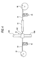
- the optical fiber 13 is unreeled from a supply reel 31 and supplied to an extruder 33 through a tension control unit 32.
- the extruder 33 has an accommodating portion 33A in which the second resin composition is accommodated, and a crosshead 33C enabled to apply the second resin composition onto the outer periphery of the optical fiber 13 by extruding the second resin composition.
- the second resin composition is applied onto the outer periphery of the optical fiber 13 when the second resin composition is put in a molten state.
- the extruder 33 has a heater (not shown) at a predetermined place.
- the optical fiber with the second resin composition which is extruded from the extruder 33 is led to a cooling water tank 34 thereby to cool and cure the outer coating 16.
- the buffered optical fiber 10 is formed.
- the buffered optical fiber 10 is wound onto a takeup reel 36 through a tension control unit 35.
- the second coating layer 16 may have either a form in which the second coating layer 16 is constituted by a single coating layer, or a form in which the second coating layer 16 consists of two or more coating layers.
- FIG. 3(A) shows a schematic cross-sectional view of the buffered optical fiber 50 in which the second coating layer comprises two or more coating layers.
- an inner layer 54 and an outer layer 55 are serially provided as the second coating layer 56 on an outer peripheral surface of the optical fiber 53, which is provided with the first coating layer 52 on the outer periphery of the glass fiber 51, in the direction in which the layers are away from the glass fiber 51.
- the first coating layer 52 is provided with the first ultraviolet curable resin layer 52A, the second ultraviolet curable resin layer 52B, and the colored layer 52C serially arranged in a direction in which these layers are away from the glass fiber 51.
- both the resin compositions respectively constituting the inner layer 54 and the outer layer 55 are collectively set to be the second resin composition.
- the second resin composition used in this second coating layer 56 comprises the base polymer (the polymer constituting the inner layer and the outer layer), and 100 to 250 weight parts of metal hydroxide and 10 to 100 weight parts of a nitrogen-based flame retardant material per 100 weight parts of the base polymer, and does not contain halogenated materials, similarly to the second resin composition used in the aforementioned second coating layer 16 (FIG. 1).
- Additives such as a hindered amine light stabilizer (HALS), an oxidation inhibitor (sulfur-based oxidation inhibitor or the like), a lubricant, an antioxidant, etc. can be added to the base polymer.
- HALS hindered amine light stabilizer
- an oxidation inhibitor sulfur-based oxidation inhibitor or the like
- a lubricant an antioxidant, etc.
- the inner layer 54 employs polystyrene-based thermoplastic polymer, polyolefin-based thermoplastic polymer, or polyphenylene ether polymer, or a mixed polymer of thesematerials as the base polymer.
- the inner layer 54 is adapted so that 100 to 250 weight parts of metal hydroxide and less than 100 weight parts of a nitrogen-based flame retardant material per 100 weight parts of the base polymer constituting the inner layer 54 are added to the base polymer.
- the outer layer 55 employs a polystyrene-based thermoplastic polymer, a polyolefin-based thermoplastic polymer, or a polyphenylene ether polymer, or a mixed polymer of these materials as the base polymer.
- the outer layer 55 is adapted so that 100 to 250 weight parts of metal hydroxide and less than 100 weight parts of a nitrogen-based flame retardant material per 100 weight parts of the base polymer constituting the outer layer 55 are added to the base polymer.
- the Young's modulus of the inner layer 54 is 1 MPa to 100 MPa (more preferably, 5 MPa to 50 MPa).
- the Young's modulus of the outer layer 55 is 200 MPa to 1500 MPa (more preferably, 250 MPa to 1000 MPa).
- the outside diameter (Dp) of a concentric part including up to the inner layer 54 is 0.3 mm ⁇ to 0.7 mm ⁇ (more preferably, 0.35 mm ⁇ to 0.60mm ⁇ )
- the outside diameter (Ds) of the concentric part including up to the outer layer 55 is 0.75 mm ⁇ to 1.0 mm ⁇ (more preferably, 0. 85 mm ⁇ to 0. 95mm ⁇ ) .
- the Young's moduli of the inner layer 54 and the outer layer 55 are preferably adjusted according to the kinds and the additions of compounds constituting the inner layer 54 and the outer layer 55.
- the first ultraviolet curable resin layer is set to be a flexible layer, while the second ultraviolet curable resin layer is set to be a solid layer. Consequently, a side pressure (an external pressure received from the outer peripheral surface of the buffered optical fiber 50), which the buffered optical fiber 50 receives, is absorbed by outer layer 55. Even when this pressure is too large for the outer layer 55 to completely absorb, this pressure can be buffered by the inner layer 54 to thereby reduce optical transmission loss caused by the reception of the pressure by the glass fiber 51.
- the Young's modulus of the first ultraviolet curable resin layer 52A is 0.5 MPa to 2MPa.
- the Young's modulus of the second ultraviolet curable resin layer 52B is 5 MPa to 1500 MPa, and that of the colored layer 52C is 500 MPa to 1500 MPa.
- the Young's modulus of the second ultraviolet curable resin layer 52B is 5MPa to 600 MPa. Where the Young's modulus of the second ultraviolet curable resin layer 52B is less than 5 MPa, the external pressure is difficult to absorb and consequently the glass fiber becomes easily damaged. On the other hand, where the Young's modulus exceeds 600 MPa, it is difficult for a blade of a coating removing tool 20 (to be described later) to cut into the second ultraviolet curable resin layer 52B. Thus, the first coating layer 52 is difficult to remove from the buffered optical fiber.
- the buffered optical fiber 50 is configured so that the first coating layer 52 is provided with the first ultraviolet curable resin layer 52A, the second ultraviolet curable resin layer 52B, and the colored layer 52C arranged in a direction in which these layers are away from the glass fiber 51.
- the first ultraviolet thermal-curable resin layer 52A and the second ultraviolet thermal-curable resin layer 52B are provided with the first ultraviolet curable resin layer 52A, the second ultraviolet curable resin layer 52B, and the colored layer 52C arranged in a direction in which these layers are away from the glass fiber 51.
- a composition obtained by adding a pigment (an organic pigment or the like) that serves as a coloring agent andapublicly known pigment dispersing agent to the ultraviolet curable resin composition can exemplify a coloring agent composition constituting the colored layer 52C.
- the coloring agent composition can preferably comprise other curable oligomers, such as epoxy (meth) acrylate, urethane acrylate, or ester-based acrylate, as polymeric oligomers.
- the second coating layer 56 is applied on the outer periphery of the optical fiber 53 obtained in the aforementioned way.
- the buffered optical fiber 50 can preferably be manufactured.
- the optical fiber 53 is unreeled from a supply reel 61 and supplied to an extruder 63 through a tension control unit 62.
- the extruder 63 has a first accommodating portion 63A in which the composition of the inner layer 54 is accommodated, a second accommodating portion 63B in which the composition of the outer layer 55 is accommodated, and a crosshead 63C enabled to apply the second coating layer 56 onto the outer periphery of the optical fiber 53 by sequentially extruding the composition of the inner layer 54 and that of the outer layer 55.
- the composition of the inner layer 54 and that of the outer layer 55 are applied onto the outer periphery of the optical fiber 53 when the compositions are put in a molten state.
- the extruder 63 has a heater (not shown) at a predetermined place.
- the optical fiber with inner and outer layers which is extruded from the extruder 63 are led to a cooling water tank 64 thereby to cool and cure the second coating layer 56.
- the buffered optical fiber 50 is formed.
- the buffered optical fibers 10 and 50 is constituted so that an amount of transmission loss variation (dB/km) defined below is equal to or less than 0.2 dB/km, and that more preferably, the amount of transmission loss variation is equal to or less than 0.1 dB/km:
- THE AMOUNT OF TRANSMISSION LOSS VARIATION the difference in quantity between the maximum loss variation and the minimum loss variation in a transmission loss amount (in dB/km at a wavelength of 1.55 ⁇ m and including a transmission loss amount generated just after the test is started) generated during a heat cycle test performed by repeating a heat cycle consisting of 0.5 hours, in which temperature is held at (-40)°C, and 0.5 hours, in which temperature is held at 85°C.
- the first resin composition constituting the first coating layer comprises a first polymer constituted by the ultraviolet curable resin, and the second coating layer has a single-layer structure.
- the first polymer means the polymer of the first resin composition.
- the buffered optical fiber adapted so that the first polymer is a silicone resin composition
- that the second coating layer comprises a resin composition containing polyphenylene oxide
- that the outside diameter of a concentric part including up to the first coating layer is 0.4 mm
- that the outside diameter of the concentric part including up to the second coating layer is 0.8 mm
- the difference in the linear expansion coefficient between the first coating layer and the second coating layer becomes obvious. This may be caused due to a large thickness of the first coating layer. Consequently, when the buffered optical fiber according to prior art 1 undergoes abrupt changes in temperature, uneven stress is applied to the glass fiber. Thus, the glass fiber is easily distorted. The amount of transmission loss variation at the heat cycle test is large. Consequently, in the case of the buffered optical fiber according to prior art 1, the transmission loss due to the change in temperature increases.
- the linear expansion coefficient of the second resin composition is equal to or less than 4.0 ⁇ 10 -4 (1/K).
- this linear expansion coefficient is that of a sheet formed by curing the second resin composition.
- the buffered optical fibers 10 and 50 according to the embodiment of the invention are constituted so that residual thermal distortion at cabling defined below is equal to or less than 150 ⁇ m: THE RESIDUAL THERMAL DISTORTION AT CABLING: the distance between an end surface of said glass fiber and that of said second coating layer in said buffered optical fiber heat-treated at 120 °C for 168 hours.
- the buffered optical fiber of the invention excels in the property of pistoning (the property by which the first coating including the glass fiber is projected from an end surface of the second coating layer by applying abrupt changes in temperature to the buffered optical fiber for a long time).
- the device according to prior art 2 is a cable (or electric wire) adapted so that the flame retardant material (no nitrogen-based flame retardant material is intended) is added to at least the outer surface and the overall sheath of the insulator covering the conductor.
- Patent document 2 describes a material for the insulator according to prior art 2, which comprises polyphenylene oxide, low-density polyethylene and SEBS as resin components. Even in the case of such an electric cable, an end surface of the conductor may protrude from the end surface of the insulator (this phenomenon is sometimes referred to as "protrusion").
- the insulator according to prior art 2 differs from the insulator of the buffered optical fiber according to the embodiment of the invention, in that the former insulator comprises no nitrogen-based flame retardant material.
- the buffered optical fiber according to the embodiment of the invention is not obtained from the prior art. Additionally, it is not ordinarily considered by those skilled in the art that the insulator according to prior art 2, which causes the problem of the "protrusion" of the optical fiber, is applied to the buffered optical fiber according to the embodiment of the invention.
- the linear expansion coefficient of the second resin composition is set to be equal to or less than 4.0 ⁇ 10 -4 (1/K), and in which "the defined residual thermal distortion at cabling is set to be equal to or less than 150 ⁇ m", are attained by making the second resin composition comprise 100 to 250 weight parts of the metal hydroxide per 100 weight parts of the second resin composition.
- the first resin composition constituting the first coating layer comprises the first polymer constituted by the ultraviolet curable resin.
- the buffered optical fiber, whose second coating layer has a two- or more-layer structure is used.
- the buffered optical fiber, which is terminated with the connector, manufactured by using the buffered optical fiber 50, whose second coating layer has a two-layer structure is described.
- a terminal of the buffered optical fiber 50 is processed by using the coating removing tool 20 (see FIG. 7).
- the buffered optical fiber 50 is held in a V-groove 23a of the coating removing tool 20.
- a part of the buffered optical fiber 50 which is positioned at a distance of about 30 mm to 100 mm from the terminal of the buffered optical fiber 50, is pinched by a fastening tool 24.
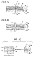
- plate-like lever members 21a, 21b are closed to thereby make a cut in the buffered optical fiber. Incidentally, as shown in FIG.
- the coating removing tool 20 is configured so that a cutting edge 22A (corresponding to an apex of the cut) of a blade 22 does not reach the glass fiber when the plate-like lever members 21a and 21b are in contact with each other.
- the glass fiber 51 is not damaged.
- the second coating layer 56 is surely cut off.
- the blade is moved in the direction of the arrows shown in FIG. 5(A).
- the first coating layer 52 and the second coating layer 56 are separated from the glass fiber 51 so as to be drawn out from the glass fiber.
- the second coating layer 56 is completely cut off.
- the first coating layer 52 is not completely cut off (the apex of the cut is positioned in the first coating layer 52).
- the first coating layer 52 is stretched for a time. A part of the first coating layer 52, which closely adheres to the glass fiber 51, is not moved together with the blade 22 (see FIG. 5 (B)). During this period, the second coating layer 56 slides on the first coating layer 52.
- the first coating layer 52 which is placed in the vicinity of the blade 22, is compressed thereat. Then, when the coating removing tool 20 is moved still more, the first coating layer 52 is torn off. Thus, the first coating layer 52' is compressed by the separated and removedpiece of the coating. Consequently, the length in a drawing-out direction of the first coating layer 52' is shorter than that in the drawing-out direction of the second coating layer 56' (see FIG. 5(C)).
- the buffered optical fiber 50 is configured so that the "length (L uv ) of the first coating layer 52' in the separated and removed piece of the coating divided by the length (L SH ) of the separated second coating layer 56"' (hereunder expressed as "L uv /L sH ”) is 15% to 85%.
- a case, in which the length in the drawing-out direction of the ultraviolet curable resin layer is equal to that in the drawing-out direction of the resin coating layer, is defined as "L uv /L sH 100%".
- the force of closing the plate-like levers 21a and 21b to separate a composite coating, which is obtained by adding the second coating layer 56 to the first coating layer 52, from the glass fiber 51 by using the coating removing tool 20 is usually 2 kgf or so.
- the rate, at which the first coating layer 52 and the second coating layer 56 are removed from the glass fiber, is about 500 mm/min.
- the force of drawing out the first coating layer 52 and the second coating layer 56 by moving the coating removing tool 20 at that time is a drawing-out force.
- the friction coefficient between the colored layer 52C (the outermost layer of the first coating layer 52) and the inner layer 54 is adjusted to 0.2 to 0.5.
- a method of adjusting the kinds and additions of compounds constituting these layers can be cited as the method of setting the friction coefficient between the colored layer 52c and the inner layer 54 to be within the aforementioned range.
- a method of adjusting the aforementioned friction coefficient by adding a decoupling agent to the colored layer 52c or to the inner layer 54 can preferably be cited.
- the colored layer 52c containing the decoupling agent is preferably obtained by using a colored layer composition to which silicone-based acrylate is added as a part of a reactive diluent monomer.
- silicone oil maybe added to the colored composition as the decoupling agent.
- silicone compounds such as silicone oil and decoupling silicone (varnish, rubber mold)
- the decoupling agent to be added to the inner layer 54.
- the decoupling agents in the range of 0.5 to 10 weight parts per 100 weight parts of the resin constituting the inner layer 54 are added to the resin constituting the inner layer.
- the compositions of the inner layer 54 and the outer layer 55 are set to be as follows.
- THE INNER LAYER 100 to 250 weight parts of metal hydroxide and less than 100 weight parts of a nitrogen-based flame retardant material are contained per 100 weight parts of polyolefin-based thermoplastic polymer.
- THE OUTER LAYER 100 to 250 weight parts of metal hydroxide and less than 100 weight parts of a nitrogen-based flame retardant material are contained per 100 weight parts of polyolefin-based thermoplastic polymer and /or thermoplastic elastomer polymer.
- the drawing-out force at the time of drawing out the first coating layer 52 and the second coating layer 56 from the glass fiber 51 is equal to or less than 2.5 kgf. Consequently, the first coating layer 52 and the second coating layer 56 are easily drawn out from the glass fiber (without feeling a large load) by using the coating removing tool 20, thereby to expose the glass fiber 51.
- the drawing-out force is defined as a force applied in the direction of drawing out the resin layer (that is, the force of pulling the coating removing tool 20).
- this setting can be handled by improving materials, which excel in melt flow ratio during extrusion, and a process (the shape of a screw, the shape of a die point) of reducing a back pressure in extrusion, as described in the description of examples.
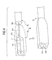
- the buffered optical fiber 19 terminated with a connector is manufactured (see FIG. 6) by connecting the buffered optical fiber 50, which has the glass fiber exposure portion 51A and the coating end surface 56A manufactured by processing the terminal of the buffered optical fiber 50, to the connector 18, which incorporates the ferrule 17 having the hollow space 17A enabled to accommodate the glass fiber exposure portion 51A. More specifically, the coating end surface 56A is made to abut against the abutting end surface 17B of the ferrule so as to accommodate the glass fiber exposure portion 51A in a state, in which no distortion force is applied to the glass fiber exposure portion 51A, in the hollow space 17A.
- the buffered optical fiber 50 and the connector 18 are connected to each other by a fastening means (not shown) to maintain this state.
- the buffered optical fiber 19 terminated with the connector has no transmission loss due to distortion.
- the end surface 51B of the glass fiber and the open end surface 17C of the ferrule are processed into desired shapes, for instance by being grounded.
- a flat surface, a spherical surface, and a curved surface can be applied as the surfaces constituted by the end surface 51B of the glass fiber and the open end surface 17C of the ferrule, and are appropriately selected according to the specifications of the buffered optical fiber 19 terminated with the connector.
- the buffered optical fiber 19 terminated with the connector there is no residue of the ultraviolet curable resin layer 12 in the glass fiber exposure portion 11A.
- the glass fiber exposure portion 51A is accommodated in the hollow space 17A.
- the coating end surface 56A is caused to abut against the a butting end surface 17B of the ferrule.
- the center of the end surface 51B of the glass fiber is present at a desired place. Therefore, in the case of the buffered optical fiber 19 terminated with the connector, there is no connection loss due to the shift of the position of the glass fiber. Consequently, the buffered optical fiber 19 terminated with the connector excels in optical transmission characteristics.
- the buffered optical fiber 50 according to the embodiment of the invention constitutes the buffered optical fiber 19 terminated with the connector.
- the buffered optical fiber 19 terminated with the connector is fire-resistant. Even when burning, toxic gas is not generated.
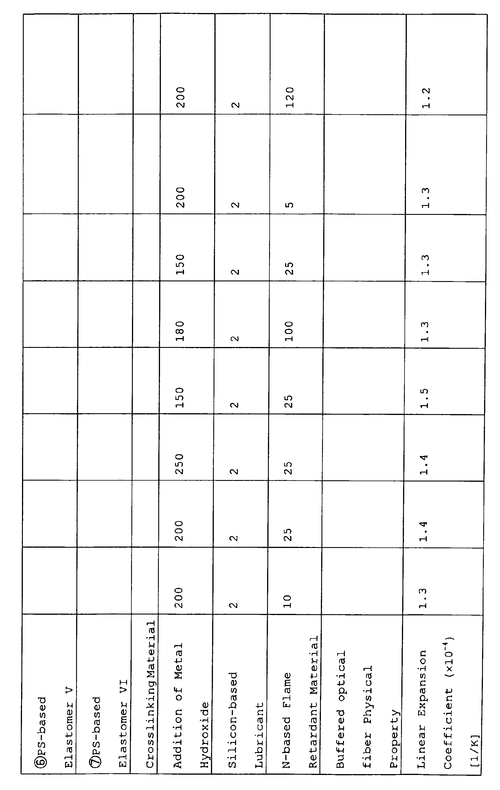
- Metal oxides and nitrogen-based flame retardant materials are added to 100 weight parts of the second polymer according to the compositions described in TABLE 1.
- the second resin compositions used in Examples 1, 2-1 to 2-3, and 3-1 to 3-2 are prepared.
- the ultraviolet curable resin layer has a three-layer structure including the first ultraviolet curable resin layer, the second ultraviolet curable resin layer, and the colored layer.
- the outside diameter of a concentric part including up to the first ultraviolet curable resin layer is 200 ⁇ m.
- the outside diameter of a concentric part including up to the second ultraviolet curable resin layer is 245 ⁇ m.
- the outside diameter of the concentric part including up to the colored layer is 255 ⁇ m.
- the Young's modulus of the first ultraviolet curable resin layer is 1 MPa (at 25°C) .
- the Young's modulus of the second ultraviolet curable resin layer is 400 MPa (at 25 °C) .
- the Young's modulus of the colored layer is 1100 MPa (at 25 °C) .
- the buffered optical fibers according to Examples 1, 2-1 to 2-3, and 3-1 to 3-3 are manufactured by providing the second resin layer on the outer periphery of this optical fiber according to the aforementioned method (the outside diameter D s : 0.9 mm).
- the extruder is connected to the crosshead (corresponding to the crosshead 33C).
- the second resin compositions used in Examples 4-1 and 4-2 are prepared by adding metal hydroxide and the nitrogen-based flame retardant material to 100 weight parts of the second polymer according to the compositions described in TABLE 2 and by performing a method similar to the method used for the Examples 1 to 3.
- Theultraviolet curable resin layer has the three-layer structure including the first ultraviolet curable resin layer, the second ultraviolet curable resin layer, and the colored layer.
- the outside diameter of a concentric part including up to the first ultraviolet curable resin layer is 200 ⁇ m.
- the outside diameter of the concentric part including up to the second ultraviolet curable resin layer is 245 ⁇ m.
- the outside diameter of the concentric part including up to the colored layer is 255 ⁇ m.
- the Young's modulus of the first ultraviolet curable resin layer is 1 MPa (at 25°C) .
- the Young's modulus of the second ultraviolet curable resin layer is 400 MPa (at 25 °C).
- the Young's modulus of the colored layer is 1100 MPa (at 25 °C) .
- the buffered optical fibers according to the Examples 4-1 and 4-2 are manufactured (the outside diameter D s : 0.9 mm).
- Buffered optical fibers according to the Comparative Examples 1 and 2 are produced according to a method similar to the method used for the Examples 1 to 3.
- the composition of the second resin composition and the characteristic values of the buffered optical fibers are described in TABLE 1.
- High Flame Retardancy 0.9 mm ⁇ Buffered Optical Fiber Second Resin Composition Example 4-1
- Example 4-2 Inner Layer Outer Layer Inner Layer Outer Layer Base Polymer (Weight Parts) 1 ⁇ PPPE (polyphenylene ether polymer) 20 80 25 85 2 ⁇ PS-based Elastomer I 3 ⁇ PS-based Elastomer II 4 ⁇ PS-based Elastomer III 79 5 ⁇ PS-based Elastomer IV 74 6 ⁇ PS-based Elastomer V 20 7 ⁇ PS-based Elastomer VI 15 Crosslinking Material 1 1
- Addition of Metal Hydroxide 240 240 250 150 Silicon-based Lubricant 2 2 N-based Flame Retardant Material 30 30
- 20 30
- a method for measuring the linear expansion coefficient of the second resin composition, and a method for measuring the Young's modulus are as follows.
- test piece a sheet formed by curing the second resin composition
- JIS K 7100 The state of a test piece (a sheet formed by curing the second resin composition) is adjusted according to JIS K 7100. ⁇ Then, the test piece is scanned in a temperature range of (-60) °C to 100 °C by using a TMA (Thermo-Mechanical-Analyzer) described in JIS K 7197.
- TMA Thermo-Mechanical-Analyzer
- the second resin composition corresponding to each of the Examples and Comparative Examples is molten and kneaded by a publicly known apparatus constituted by a biaxial kneader/extruder, a pressure kneader, a Banbury mixer, a roll, and the like.
- a film object having a thickness of about 300 ⁇ m is formed.
- a test piece of No. 2 type (according to JIS K 7113) shaped like a dumbbell is manufactured from this film object.
- the Young's modulus is defined as that which is measured by using this test piece and performing a tension test under the conditions that the distance between benchmarks is 25 mm and the pulling rate is 1 mm/minute.
- the evaluation of the buffered optical fiber is performed as follows.
- a heat treatment is performed on the buffered optical fiber, which is adapted so that end surfaces of the glass fiber, the first coating layer, and the second coating layer are disposed on the same surface, under the conditions that the buffered optical fiber is heated at 120 °C for 168 hours.
- the "distance between the end surface of the glass fiber and that of the second coating layer" is measured as the residual thermal distortion at cabling.
- the amount (dB) of transmission loss of the buffered optical fiber is measured (at 23 °C) by using an OTDR measuring device (the wavelength: 1.55 ⁇ m)
- the transmission loss per unit length is indicated as an "initial loss" (dB/km). The lower the value of the initial loss becomes, the more the buffered optical fiber excels in the optical transmission characteristics.
- Heat cycle exposure tests are repeatedly performed (the number of times: 5) on the buffered optical fiber by repeating a heat cycle consisting of 0.5 hours, in which the temperature is held at (-40) °C, and 0.5 hours, in which the temperature is held at 85 °C.
- an amount (dB) of transmission loss is measured by continuous monitoring (at the wavelength: 1. 55 ⁇ m) .
- the difference in quantity between the maximum loss variation and the minimum loss variation in a transmission loss amount is indicated as the amount of transmission loss variation (dB/km). The lower the value of the amount of transmission loss variation becomes, the more the buffered optical fiber excels in the temperature change resistance property.
- the heat cycle exposure test described in the description of the temperature change resistance property is performed on the buffered optical fiber 200 times.
- the amount of protrusion of the glass fiber (the distance between an end surface of the glass fiber and an end surface of the second coating layer) is measured. Results thereof are described in TABLE 2. The lower the amount of protrusion becomes, the more the buffered optical fiber excels in the pistoning property.
- the appearance of the buffered optical fiber is checked by visually observing the buffered optical fiber and by touching the buffered optical fiber with the hands. If the buffered optical fiber meets the conditions that neither "roughness of the surface shape" nor "convex foreign substances each having a size of about 10 ⁇ m to 100 ⁇ m" are present, it is judged that the appearance of the buffered optical fiber is good ( ⁇ ). Conversely, if the buffered optical fiber does not meet such conditions, it is judged that the appearance of the buffered optical fiber is bad ( ⁇ ).
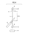
- a test on the flame retardancy of the buffered optical fiber is performed according to the standard UL1581 VW-1.
- the top portion of the buffered optical fiber 10 (or 50) having a predetermined length is gripped by a gripping portion 84, while the bottom portion of the buffered optical fiber 10 is gripped by another gripping portion 85.
- the optical fiber 10 is set so that its longitudinal direction is the vertical direction.
- Absorbent cotton 83 is placed under the bottom portion of the buffered optical fiber 10.
- Kraft paper 81 is pasted to a place that is slightly lower than the gripping portion 84 for the buffered optical fiber 10.
- burner flames are spewed by a burner 82 to the position, which is lower than the Kraft paper 81 by 254 mm (during 5 cycles each consisting of a ignition time of 15 seconds and a quenching time of 15 seconds) .
- the burner flames are such that the length of an inner flame is 40 mm, and that the length of an outer flame is 125 mm.
- the resin layers are removed from a part of the buffered optical fiber, which has a length of 30 mm from a terminal of the buffered optical fiber, by using a "coating remover JR-22" ("JR-22" is the trade name of the coating remover manufactured by Sumitomo Electric Industries, Ltd.) corresponding to the coating removing tool shown in FIG. 7.
- JR-22 is the trade name of the coating remover manufactured by Sumitomo Electric Industries, Ltd.
- the drawing-out force (kgf) is measured by setting a drawing-out rate at 500 m/minute.
- the drawing-out force of the buffered optical fiber of each of the Examples 4-1 and 4-2 is equal to or less than 2.5 kgf.
- the buffered optical fibers according to the examples excel in appearance and flame retardancy.
- the buffered optical fiber according to the comparative example 1 is inferior in flame retardancy, because the amount of the contained nitrogen-based flame retardant material is too small.
- the buffered optical fiber according to the comparative example 2 is inferior in appearance, because the amount of the nitrogen-based flame retardant material is too large.
- the second resin composition constituting each of the second coating layers of the buffered optical fibers according to the examples and the comparative examples does not contain halogenated materials and phosphorus.
- the buffered optical fibers do not pollute the environment system. That is, when the second polymer burns, the generation of toxic gas is reduced. Further, it restrains rivers and lakes from being polluted owing to a hypertrophic condition brought by phosphate compounds which flow into the rivers and the lakes.
- the invention can provide a buffered optical fiber enabled not to pollute the environment system, having high flame retardancy, and enabled to reduce degradation of optical transmission characteristics even when a connector is connected to the buffered optical fiber, and can also provide a connecter-terminated buffered optical fiber that excels in environmental characteristics, mechanical characteristics, and optical transmission characteristics.
Landscapes
- Life Sciences & Earth Sciences (AREA)
- Physics & Mathematics (AREA)
- Chemical & Material Sciences (AREA)
- Engineering & Computer Science (AREA)
- General Life Sciences & Earth Sciences (AREA)
- Optics & Photonics (AREA)
- General Physics & Mathematics (AREA)
- Chemical Kinetics & Catalysis (AREA)
- General Chemical & Material Sciences (AREA)
- Geochemistry & Mineralogy (AREA)
- Materials Engineering (AREA)
- Organic Chemistry (AREA)
- Optical Fibers, Optical Fiber Cores, And Optical Fiber Bundles (AREA)
- Surface Treatment Of Glass Fibres Or Filaments (AREA)
Abstract
Description
Patent Document 1: JP-A-62-99708.
Patent Document 2: JP-A-8-138454.
THE AMOUNT OF TRANSMISSION LOSS VARIATION: the difference in quantity between the maximum loss variation and the minimum loss variation in a transmission loss amount (in dB/km at a wavelength of 1.55 µm and including a transmission loss amount generated just after the test is started) generated during a heat cycle exposure test performed by repeating a heat cycle consisting of 0.5 hours, in which the temperature is held at (-40)°C, and 0.5 hours, in which the temperature is held at 85 °C.
THE RESIDUAL THERMAL DISTORTION AT CABLING: the distance between an end surface of said glass fiber and that of said second coating layer in said buffered optical fiber heat-treated at 120 °C for 168 hours.



| High Flame Retardancy 0.9 mm Buffered Optical Fiber | ||||
| Second Resin Composition | Example 4-1 | Example 4-2 | ||
| Inner Layer | Outer Layer | Inner Layer | Outer Layer | |
| Base Polymer (Weight Parts) | ||||
| 1 ○PPPE (polyphenylene ether polymer) | 20 | 80 | 25 | 85 |
| 2 ○ PS-based Elastomer I | ||||
| 3 ○PS-based Elastomer II | ||||
| 4 ○ PS-based Elastomer III | 79 | |||
| 5 ○ PS-based Elastomer IV | 74 | |||
| 6 ○PS-based | 20 | |||
| 7 ○PS-based Elastomer VI | 15 | |||
| Crosslinking Material | 1 | 1 | ||
| Addition of Metal Hydroxide | 240 | 240 | 250 | 150 |
| Silicon-based Lubricant | 2 | 2 | ||
| N-based Flame Retardant Material | 30 | 30 | 20 | 30 |
| Buffered optical fiber Physical Property | ||||
| Linear Expansion Coefficient (×10-4) [1/K] | 1.8 | 1.1 | 1.7 | 1.2 |
| Young's Modulus [MPa] | 120 | 850 | 150 | 700 |
| Optical fiber Characteristics | ||||
| Residual thermal Distortion (120°C×168hr) [µm/m] | 150 | 150 | 145 | 145 |
| Optical Transmission Loss Characteristics (Room Temperature) [dB/km] | 0.195 | 0.186 | ||
| Temperature Change Resistance Property Δα (-40 - 85°C) [dB/km] | 0.06 | 0.06 | ||
| Amount of Protusion (µm/m) | - | - | - | - |
| Appearance | O | O | O | O |
| Flame Retardancy (UL1581 Burning Test) | O | O | O | O |
| Luv/LSH (%) | 80 | 85 |
Claims (13)
- A buffered optical fiber having a second coating layer on an outer peripheral surface of an optical fiber produced by providing a first coating layer on an outer peripheral surface of a glass fiber,
wherein a second resin composition constituting the second coating layer comprises a base polymer, and 100 to 250 weight parts of metal hydroxide and 10 to 100 weight parts of a nitrogen-based flame retardant material per 100 weight parts of the base polymer,
and wherein the second resin composition does not contain halogenated materials. - The buffered optical fiber according to claim 1, wherein the base polymer is constituted by a noncrystalline resin.
- The buffered optical fiber according to claim 1 or 2, wherein the second resin composition comprises, as the base polymer, one of components selected from the group consisting of a polystyrene-based polymer, a polystyrene-based elastomer, a mixture of polystyrene-based polymer and polyphenylene ether polymer, and a mixture of polystyrene-based elastomer and polyphenylene ether polymer.
- The buffered optical fiber according to claim 3, wherein a part of the polystyrene-based polymer or the polystyrene-based elastomer is subjected to acid modification.
- The buffered optical fiber according to one of claims 1 to 4, wherein the second coating layer is formed of two or more coating layers.
- The buffered optical fiber according to one of claims 1 to 5, wherein the buffered optical fiber is constituted so that an amount of transmission loss variation (dB/km) is equal to or less than 0.2 dB/km, said
AMOUNT OF TRANSMISSION LOSS VARIATION comprising: a difference in quantity between a maximum loss variation and a minimum loss variation in a transmission loss amount (in dB/km at a wavelength of 1.55 µm and including a transmission loss amount generated just after the test is started) generated during a heat cycle exposure test performed by repeating a heat cycle consisting of 0.5 hours, in which temperature is held at (-40) °C, and 0.5 hours, in which temperature is held at 85°C. - The buffered optical fiber according to one of claims 1 to 6, wherein the linear expansion coefficient of the second resin composition is equal to or less than 4.0×10⁻⁴ (1/K).
- The buffered optical fiber according to one of claims 1 to 7, wherein residual thermal distortion at cabling is equal to or less than 150 µm, said
RESIDUAL THERMAL DISTORTION AT CABLING comprising: a distance between an end surface of said glass fiber and an end surface of said second coating layer in said buffered optical fiber which is heat-treated at 120 °C for 168 hours. - The buffered optical fiber according to claim 5, wherein said buffered optical fiber has said first coating layer of an ultraviolet curable resin layer and said buffered optical fiber is configured so that when a cut is made in the direction from said second coating layer to said glass fiber so as not to allow an apex of the cut to reach said glass fiber and the ultraviolet curable resin layer and said second coating layer are separated from said glass fiber by drawing them out of the glass fiber, a "ratio of a length of said ultraviolet curable resin layer in a separated and removed coat piece to a length of said separated second coating layer" is 15 % to 85 %.
- The buffered optical fiber according to claim 9, wherein an inner layer and an outer layer are serially provided as said second coating layer on an outer peripheral surface of said optical fiber in a direction in which said layers are away from said optical fiber, said inner layer being derived by adding 100 to 250 weight parts of metal hydroxide and less than 100 weight parts of a nitrogen-based flame retardant material per 100 weight parts of polystyrene-based thermoplastic polymer, polyolefin-based thermoplastic polymer, or polyphenylene ether polymer, or a mixed polymer of these materials.
- The buffered optical fiber according to claim 9, wherein an inner layer and an outer layer are serially provided as said second coating layer on an outer peripheral surface of said optical fiber in a direction in which said layers are away from the optical fiber, wherein said outer layer being derived by adding 100 to 250 weight parts of metal hydroxide and less than 100 weight parts of a nitrogen-based flame retardant material per 100 weight parts of polystyrene-based thermoplastic polymer, polyolefin-based thermoplastic polymer, or polyphenylene ether polymer, or a mixed polymer of these materials.
- The buffered optical fiber according to claim 9, which is constituted so that a drawing-out force on drawing out said ultraviolet curable resin layer and said second coating layer from said glass fiber is equal to or less than 2.5 kgf.
- A buffered optical fiber terminated with a connector obtained by connecting a buffered optical fiber according to one of claims 1 to 12, which is configured by exposing a part having a predetermined length from an end of said glass fiber thereby to have a glass fiber exposure portion and a coating end surface and a connector incorporating a ferrule that has a hollow space enabled to accommodate the glass fiber exposure portion, wherein the coating end surface abuts against an abutting end surface of said ferrule so as to accommodate said glass fiber exposure portion in a state, in which no distortion force is applied thereto, in the hollow space.
Applications Claiming Priority (5)
| Application Number | Priority Date | Filing Date | Title |
|---|---|---|---|
| JP2003043338A JP3912531B2 (en) | 2003-02-20 | 2003-02-20 | Coated optical fiber |
| JP2003043338 | 2003-02-20 | ||
| JP2003044074 | 2003-02-21 | ||
| JP2003044074A JP3912532B2 (en) | 2002-02-21 | 2003-02-21 | Coated optical fiber core, coated optical fiber core with connector, and optical fiber cable |
| PCT/JP2004/001888 WO2004074898A1 (en) | 2003-02-20 | 2004-02-19 | Coated optical fiber and coated optical fiber with connector |
Publications (2)
| Publication Number | Publication Date |
|---|---|
| EP1596234A1 true EP1596234A1 (en) | 2005-11-16 |
| EP1596234A4 EP1596234A4 (en) | 2006-03-22 |
Family
ID=32911420
Family Applications (1)
| Application Number | Title | Priority Date | Filing Date |
|---|---|---|---|
| EP04712701A Withdrawn EP1596234A4 (en) | 2003-02-20 | 2004-02-19 | COATED OPTICAL FIBER AND COATED OPTICAL FIBER HAVING A CONNECTOR |
Country Status (3)
| Country | Link |
|---|---|
| US (1) | US7542644B2 (en) |
| EP (1) | EP1596234A4 (en) |
| WO (1) | WO2004074898A1 (en) |
Cited By (5)
| Publication number | Priority date | Publication date | Assignee | Title |
|---|---|---|---|---|
| EP2101205A1 (en) * | 2008-03-13 | 2009-09-16 | Tratos Cavi S.p.A. | Fibre optic cable and method for its installation |
| EP2028514A4 (en) * | 2006-06-12 | 2010-04-21 | Furukawa Electric Co Ltd | AME OF OPTICAL FIBER AND PROCADA OF PRODUCTION THEREOF |
| EP2075605A4 (en) * | 2007-02-08 | 2011-11-09 | Sumitomo Electric Industries | OPTICAL CABLE |
| EP2977806A4 (en) * | 2013-03-22 | 2016-01-27 | Mitsubishi Rayon Co | OPTICAL FIBER CABLE |
| EP2977805A4 (en) * | 2013-03-22 | 2016-01-27 | Mitsubishi Rayon Co | OPTICAL FIBER CABLE AND MOBILE VEHICLE |
Families Citing this family (23)
| Publication number | Priority date | Publication date | Assignee | Title |
|---|---|---|---|---|
| US7665116B2 (en) * | 2004-10-27 | 2010-02-16 | Arris Group, Inc. | Network architecture for real time delivery of video over lossy networks from remote locations |
| JP4325687B2 (en) | 2007-02-23 | 2009-09-02 | 株式会社デンソー | Electronic equipment |
| JP5008644B2 (en) * | 2008-02-25 | 2012-08-22 | 株式会社フジクラ | Optical ferrule with optical fiber |
| JP4657327B2 (en) * | 2008-07-17 | 2011-03-23 | 三菱電線工業株式会社 | Connector fixing structure to optical fiber core |
| JP2010152340A (en) * | 2008-11-18 | 2010-07-08 | Fujikura Ltd | Optical fiber cable and resin composition used for the same |
| US8998507B2 (en) * | 2010-02-11 | 2015-04-07 | Corning Incorporated | Fiber optic connectors and structures for optical fibers and methods for using the same |
| JP6145632B2 (en) * | 2011-06-14 | 2017-06-14 | 三菱ケミカル株式会社 | Optical fiber coating composition and optical fiber cable |
| US8855455B2 (en) * | 2011-11-23 | 2014-10-07 | Nexans | Fiber optic cable |
| TWI571664B (en) * | 2012-09-14 | 2017-02-21 | 鴻海精密工業股份有限公司 | Silicon bench |
| US10222547B2 (en) | 2015-11-30 | 2019-03-05 | Corning Incorporated | Flame-retardant optical fiber coating |
| US11169323B2 (en) * | 2016-04-15 | 2021-11-09 | Zeus Industrial Products, Inc. | Thermoplastic-coated optical elements |
| WO2018062365A1 (en) | 2016-09-30 | 2018-04-05 | 株式会社フジクラ | Optical fiber ribbon, optical fiber cable, and method for manufacturing optical fiber ribbon |
| KR102325812B1 (en) * | 2016-09-30 | 2021-11-11 | 가부시키가이샤후지쿠라 | Optical fiber colored core wire, fiber optic cable and manufacturing method of optical fiber colored core wire |
| US10167396B2 (en) | 2017-05-03 | 2019-01-01 | Corning Incorporated | Low smoke fire-resistant optical ribbon |
| US11287590B2 (en) * | 2017-06-12 | 2022-03-29 | Corning Research & Development Corporation | In-road interface protected cable |
| JP6728107B2 (en) | 2017-06-22 | 2020-07-22 | 株式会社クボタ | Grass management system |
| DE102017123922A1 (en) * | 2017-10-13 | 2019-04-18 | Rheinisch-Westfälische Technische Hochschule (Rwth) Aachen | Multi-component fiber and method of manufacture |
| CN111902442B (en) | 2018-04-02 | 2023-04-04 | 住友电气工业株式会社 | Resin composition, secondary coating material for optical fiber, and optical fiber |
| KR102669759B1 (en) | 2018-04-16 | 2024-05-27 | 스미토모 덴키 고교 가부시키가이샤 | optical fiber |
| JP7327405B2 (en) | 2018-08-22 | 2023-08-16 | 住友電気工業株式会社 | optical fiber |
| CN112654908B (en) | 2018-09-13 | 2023-03-24 | 古河电气工业株式会社 | Optical fiber core wire and optical fiber cable |
| JP7484907B2 (en) * | 2019-06-18 | 2024-05-16 | 住友電気工業株式会社 | Optical Fiber |
| DE102019120052A1 (en) * | 2019-07-24 | 2021-01-28 | SchäferRolls GmbH & Co. KG | Industrial roll, in particular for paper production, method for introducing a polymer fiber into an empty tube of a technical roll and using a polymer fiber |
Family Cites Families (15)
| Publication number | Priority date | Publication date | Assignee | Title |
|---|---|---|---|---|
| JP2777384B2 (en) | 1988-11-28 | 1998-07-16 | 株式会社フジクラ | Loose tube core |
| JPH02212339A (en) | 1989-02-10 | 1990-08-23 | Fujikura Ltd | Production of loose-tube coated fiber |
| EP0778589B1 (en) * | 1995-12-08 | 2001-11-28 | Alcatel | Communication cable for use in a plenum |
| DE19648799A1 (en) * | 1996-11-26 | 1998-05-28 | Basf Ag | Halogen-free, flame-retardant polystyrene molding compounds |
| JP2000241676A (en) | 1999-02-24 | 2000-09-08 | Toyokuni Electric Cable Co Ltd | Optical fiber |
| JP2000351920A (en) | 1999-06-11 | 2000-12-19 | Takeda Chem Ind Ltd | Resin composition for optical fiber coating |
| JP3515501B2 (en) | 1999-08-30 | 2004-04-05 | リケンテクノス株式会社 | Flame-retardant resin composition and molded part using the same |
| JP2001083380A (en) | 1999-09-14 | 2001-03-30 | Sumitomo Electric Ind Ltd | Optical fiber |
| JP4497632B2 (en) | 1999-11-11 | 2010-07-07 | 旭化成ケミカルズ株式会社 | Flame retardant resin composition |
| JP2001278641A (en) | 2000-03-31 | 2001-10-10 | Sumitomo Electric Ind Ltd | Manufacturing method of optical fiber core |
| JP2002088253A (en) * | 2000-09-14 | 2002-03-27 | Asahi Kasei Corp | Non-halogen flame-retardant polymer molding |
| JP4715981B2 (en) * | 2001-01-22 | 2011-07-06 | 住友電気工業株式会社 | Flame retardant optical fiber ribbon |
| US6727303B2 (en) * | 2001-08-30 | 2004-04-27 | Teijin Chemicals, Ltd. | Flame retardant aromatic polycarbonate resin composition and molded articles thereof |
| US6722790B2 (en) * | 2002-01-04 | 2004-04-20 | Panduit Corp. | Contoured internal stub crimp backbone |
| WO2004040348A1 (en) * | 2002-10-28 | 2004-05-13 | Judd Wire, Inc. | Fiber optic cable demonstrating improved dimensional stability |
-
2004
- 2004-02-19 WO PCT/JP2004/001888 patent/WO2004074898A1/en not_active Ceased
- 2004-02-19 EP EP04712701A patent/EP1596234A4/en not_active Withdrawn
- 2004-02-19 US US10/523,994 patent/US7542644B2/en not_active Expired - Fee Related
Cited By (5)
| Publication number | Priority date | Publication date | Assignee | Title |
|---|---|---|---|---|
| EP2028514A4 (en) * | 2006-06-12 | 2010-04-21 | Furukawa Electric Co Ltd | AME OF OPTICAL FIBER AND PROCADA OF PRODUCTION THEREOF |
| EP2075605A4 (en) * | 2007-02-08 | 2011-11-09 | Sumitomo Electric Industries | OPTICAL CABLE |
| EP2101205A1 (en) * | 2008-03-13 | 2009-09-16 | Tratos Cavi S.p.A. | Fibre optic cable and method for its installation |
| EP2977806A4 (en) * | 2013-03-22 | 2016-01-27 | Mitsubishi Rayon Co | OPTICAL FIBER CABLE |
| EP2977805A4 (en) * | 2013-03-22 | 2016-01-27 | Mitsubishi Rayon Co | OPTICAL FIBER CABLE AND MOBILE VEHICLE |
Also Published As
| Publication number | Publication date |
|---|---|
| EP1596234A4 (en) | 2006-03-22 |
| US20060088263A1 (en) | 2006-04-27 |
| WO2004074898A1 (en) | 2004-09-02 |
| US7542644B2 (en) | 2009-06-02 |
Similar Documents
| Publication | Publication Date | Title |
|---|---|---|
| US7542644B2 (en) | Coated optical fiber and coated optical fiber with connector | |
| AU2007357076B2 (en) | Telecommunication cable equipped with tight-buffered optical fibers | |
| CN100514106C (en) | Optical cable with low contractibility rate cable sheath and its production method | |
| EP2069253B1 (en) | Buffered optical fibre and method for improving the lifetime thereof | |
| EP3270201B1 (en) | Fiber optic cable | |
| JP3515501B2 (en) | Flame-retardant resin composition and molded part using the same | |
| CN108369324A (en) | Fiber Ribbon and Fiber Optic Cable | |
| WO2020069053A1 (en) | Small diameter fiber optic cables having low-friction cable jackets and optical fibers with reduced cladding and coating diameters | |
| EP1376181B1 (en) | Buffered optical fibers and methods of making same | |
| JP3912531B2 (en) | Coated optical fiber | |
| EP3331833A1 (en) | Re-coated optical fibers and methods of re-coating optical fibers | |
| US20080170828A1 (en) | Indoor cable assemblies with flexible network access point | |
| KR100483980B1 (en) | Heat strippable optical fiber ribbons | |
| JP3955829B2 (en) | Optical fiber core | |
| JP4525387B2 (en) | Optical fiber cord | |
| JP3761382B2 (en) | Optical fiber cord and optical fiber cable | |
| JP3889287B2 (en) | Plastic optical fiber cable and plastic optical fiber cable with plug | |
| JP4277680B2 (en) | Flame retardant resin composition and optical fiber cord using the same | |
| JP4096181B2 (en) | Optical fiber cord | |
| JP2010066382A (en) | Coated optical fiber core | |
| JP4466072B2 (en) | Optical fiber cord | |
| JP4058618B2 (en) | Coated optical fiber core, coated optical fiber core with connector, optical fiber cord, optical fiber cord with connector, and optical fiber cable | |
| JP2001083380A (en) | Optical fiber | |
| EP4206773A1 (en) | Fire retardant strength member for optical fiber cables and manufacturing method thereof | |
| JP2019179627A (en) | Wiring material |
Legal Events
| Date | Code | Title | Description |
|---|---|---|---|
| PUAI | Public reference made under article 153(3) epc to a published international application that has entered the european phase |
Free format text: ORIGINAL CODE: 0009012 |
|
| 17P | Request for examination filed |
Effective date: 20050125 |
|
| AK | Designated contracting states |
Kind code of ref document: A1 Designated state(s): AT BE BG CH CY CZ DE DK EE ES FI FR GB GR HU IE IT LI LU MC NL PT RO SE SI SK TR |
|
| AX | Request for extension of the european patent |
Extension state: AL LT LV MK |
|
| A4 | Supplementary search report drawn up and despatched |
Effective date: 20060202 |
|
| RIC1 | Information provided on ipc code assigned before grant |
Ipc: G02B 6/02 20060101ALI20060127BHEP Ipc: C03C 25/10 20060101AFI20060127BHEP |
|
| DAX | Request for extension of the european patent (deleted) | ||
| RBV | Designated contracting states (corrected) |
Designated state(s): DE FR GB IT |
|
| 17Q | First examination report despatched |
Effective date: 20071130 |
|
| STAA | Information on the status of an ep patent application or granted ep patent |
Free format text: STATUS: THE APPLICATION HAS BEEN WITHDRAWN |
|
| 18W | Application withdrawn |
Effective date: 20120117 |