EP1596215A2 - Positioning apparatus, positioning method, positioning program, and computer-readable recording medium for recording positioning program - Google Patents
Positioning apparatus, positioning method, positioning program, and computer-readable recording medium for recording positioning program Download PDFInfo
- Publication number
- EP1596215A2 EP1596215A2 EP05010237A EP05010237A EP1596215A2 EP 1596215 A2 EP1596215 A2 EP 1596215A2 EP 05010237 A EP05010237 A EP 05010237A EP 05010237 A EP05010237 A EP 05010237A EP 1596215 A2 EP1596215 A2 EP 1596215A2
- Authority
- EP
- European Patent Office
- Prior art keywords
- positioning
- information
- sps
- indicator information
- reception environment
- Prior art date
- Legal status (The legal status is an assumption and is not a legal conclusion. Google has not performed a legal analysis and makes no representation as to the accuracy of the status listed.)
- Withdrawn
Links
- 238000000034 method Methods 0.000 title claims description 13
- 238000011156 evaluation Methods 0.000 claims abstract description 24
- 230000006870 function Effects 0.000 description 12
- 238000007405 data analysis Methods 0.000 description 8
- 238000010586 diagram Methods 0.000 description 6
- 230000002542 deteriorative effect Effects 0.000 description 5
- 238000012545 processing Methods 0.000 description 4
- 238000004458 analytical method Methods 0.000 description 3
- 230000008569 process Effects 0.000 description 3
- GINJFDRNADDBIN-FXQIFTODSA-N bilanafos Chemical compound OC(=O)[C@H](C)NC(=O)[C@H](C)NC(=O)[C@@H](N)CCP(C)(O)=O GINJFDRNADDBIN-FXQIFTODSA-N 0.000 description 2
- 230000008859 change Effects 0.000 description 2
- 230000006866 deterioration Effects 0.000 description 2
- 102100036848 C-C motif chemokine 20 Human genes 0.000 description 1
- 101000713099 Homo sapiens C-C motif chemokine 20 Proteins 0.000 description 1
- 101100460719 Mus musculus Noto gene Proteins 0.000 description 1
- 101100187345 Xenopus laevis noto gene Proteins 0.000 description 1
- 238000004891 communication Methods 0.000 description 1
- 238000010276 construction Methods 0.000 description 1
- 238000007796 conventional method Methods 0.000 description 1
- 230000003247 decreasing effect Effects 0.000 description 1
- 238000010790 dilution Methods 0.000 description 1
- 239000012895 dilution Substances 0.000 description 1
- 230000005684 electric field Effects 0.000 description 1
- 238000012986 modification Methods 0.000 description 1
- 230000004048 modification Effects 0.000 description 1
- 239000004065 semiconductor Substances 0.000 description 1
Images




Classifications
-
- G—PHYSICS
- G01—MEASURING; TESTING
- G01S—RADIO DIRECTION-FINDING; RADIO NAVIGATION; DETERMINING DISTANCE OR VELOCITY BY USE OF RADIO WAVES; LOCATING OR PRESENCE-DETECTING BY USE OF THE REFLECTION OR RERADIATION OF RADIO WAVES; ANALOGOUS ARRANGEMENTS USING OTHER WAVES
- G01S19/00—Satellite radio beacon positioning systems; Determining position, velocity or attitude using signals transmitted by such systems
- G01S19/01—Satellite radio beacon positioning systems transmitting time-stamped messages, e.g. GPS [Global Positioning System], GLONASS [Global Orbiting Navigation Satellite System] or GALILEO
- G01S19/03—Cooperating elements; Interaction or communication between different cooperating elements or between cooperating elements and receivers
- G01S19/05—Cooperating elements; Interaction or communication between different cooperating elements or between cooperating elements and receivers providing aiding data
-
- G—PHYSICS
- G01—MEASURING; TESTING
- G01S—RADIO DIRECTION-FINDING; RADIO NAVIGATION; DETERMINING DISTANCE OR VELOCITY BY USE OF RADIO WAVES; LOCATING OR PRESENCE-DETECTING BY USE OF THE REFLECTION OR RERADIATION OF RADIO WAVES; ANALOGOUS ARRANGEMENTS USING OTHER WAVES
- G01S1/00—Beacons or beacon systems transmitting signals having a characteristic or characteristics capable of being detected by non-directional receivers and defining directions, positions, or position lines fixed relatively to the beacon transmitters; Receivers co-operating therewith
-
- G—PHYSICS
- G01—MEASURING; TESTING
- G01S—RADIO DIRECTION-FINDING; RADIO NAVIGATION; DETERMINING DISTANCE OR VELOCITY BY USE OF RADIO WAVES; LOCATING OR PRESENCE-DETECTING BY USE OF THE REFLECTION OR RERADIATION OF RADIO WAVES; ANALOGOUS ARRANGEMENTS USING OTHER WAVES
- G01S19/00—Satellite radio beacon positioning systems; Determining position, velocity or attitude using signals transmitted by such systems
- G01S19/01—Satellite radio beacon positioning systems transmitting time-stamped messages, e.g. GPS [Global Positioning System], GLONASS [Global Orbiting Navigation Satellite System] or GALILEO
- G01S19/13—Receivers
-
- G—PHYSICS
- G01—MEASURING; TESTING
- G01S—RADIO DIRECTION-FINDING; RADIO NAVIGATION; DETERMINING DISTANCE OR VELOCITY BY USE OF RADIO WAVES; LOCATING OR PRESENCE-DETECTING BY USE OF THE REFLECTION OR RERADIATION OF RADIO WAVES; ANALOGOUS ARRANGEMENTS USING OTHER WAVES
- G01S19/00—Satellite radio beacon positioning systems; Determining position, velocity or attitude using signals transmitted by such systems
- G01S19/01—Satellite radio beacon positioning systems transmitting time-stamped messages, e.g. GPS [Global Positioning System], GLONASS [Global Orbiting Navigation Satellite System] or GALILEO
- G01S19/13—Receivers
- G01S19/24—Acquisition or tracking or demodulation of signals transmitted by the system
- G01S19/28—Satellite selection
-
- G—PHYSICS
- G01—MEASURING; TESTING
- G01S—RADIO DIRECTION-FINDING; RADIO NAVIGATION; DETERMINING DISTANCE OR VELOCITY BY USE OF RADIO WAVES; LOCATING OR PRESENCE-DETECTING BY USE OF THE REFLECTION OR RERADIATION OF RADIO WAVES; ANALOGOUS ARRANGEMENTS USING OTHER WAVES
- G01S5/00—Position-fixing by co-ordinating two or more direction or position line determinations; Position-fixing by co-ordinating two or more distance determinations
- G01S5/02—Position-fixing by co-ordinating two or more direction or position line determinations; Position-fixing by co-ordinating two or more distance determinations using radio waves
- G01S5/14—Determining absolute distances from a plurality of spaced points of known location
Definitions
- the present invention relates to a positioning apparatus, a positioning method, a positioning program, and a computer-readable recording medium for recording a positioning program.
- a SPS (Satellite Positioning System) apparatus has been used as a positioning system for positioning using manmade satellites.
- the SPS apparatus is constructed so as to determine its position by receiving signals from four satellites, for example.
- the SPS apparatus performs positioning by selecting four SPS satellites from a large number of satellites located in the sky and receiving the signals therefrom.
- DOP Different Operating Precision
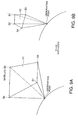
- Fig. 9A and 9B of the instant disclosure is a schematic explanatory view of the DOP values.
- Fig. 9A is a schematic explanatory view showing an example of a small DOP value
- Fig. 9B is a schematic explanatory view showing an example of a large DOP value.
- Fig. 9B when the SPS apparatus selects SPS satellites S1 to S4 close to one another, the volume of a quadrangular pyramid formed by the four SPS satellites S1 to S4 becomes smaller and the DOP value becomes larger.
- Fig. 9B when the SPS apparatus selects SPS satellites S1 to S4 close to one another, the volume of a quadrangular pyramid formed by the four SPS satellites S1 to S4 becomes smaller and the DOP value becomes larger.
- the SPS apparatus when the SPS apparatus selects SPS satellites S5 to S8 widely spaced from one another, the volume of a quadrangular pyramid formed by the four SPS satellites S5 to S8 becomes larger and the DOP value becomes smaller. Therefore, the SPS apparatus can improve the positioning precision by selecting SPS satellites S5 etc. that make the DOP value smaller.
- the SPS apparatus selects SPS satellites to make the DOP value smaller, in cases of an environment having poor reception conditions for electric waves received from the selected SPS satellites , the positioning precision becomes lower, even though the DOP value is small.
- the positioning precision worsens, reliability of the DOP value deteriorating becomes a problem.
- satellite selection indicator information such as DOP values
- the aforementioned object isrealized by a positioning apparatus.
- the positioning apparatus includes a satellite selection indicator information generating device, a positioning device, and an outputting device.
- the satellite selection indicator information generating device generates satellite selection indicator information based on satellite location information of SPS located in the sky to select a plurality of the SPS used for positioning.
- the positioning device acquires positioning information using the plurality of SPS selected based on the satellite selection indicator information.
- the outputting device outputs the positioning information.
- the positioning apparatus is characterized a reception environment indicator information generating device.
- the reception environment indicator information generating device generates reception environment indicator information of the SPS that can be balanced against the satellite selection indicator information with respect to positioning precision.
- the positioning precision is calculated based on reception environment information contained in electric waves from the SPS.
- the positioning apparatus is also characterized by a positioning information evaluation device that determines whether the positioning information is to be output to the outputting device or not based on the satellite selection indicator information and the reception environment indicator information.
- the satellite selection indicator information generating device generates DOP values, for example, as satellite selection indicator information based on the satellite location information of SPS located in the sky.
- the DOP value expresses the size of the volume of a quadrangular pyramid formed by four of the SPS. Further, the larger the volume, the smaller the numeric value becomes.
- this numeric value when the number of target SPS is five or more, for example, plural DOP values are obtained according to combinations of the SPS. For example, there are plural DOP values such as "10, 9, 8".
- the satellite selection indicator information generating device when the satellite selection indicator information is DOP, the satellite selection indicator information generating device generates the smallest DOP value, for example, "8" as the satellite selection indicator passing value.
- the positioning device acquires latitude, longitude, and altitude information as the positioning information, using in this example the plural SPS corresponding to the DOP value "8" which is the satellite selection indicator passing value.
- the reception environment indicator information generating device generates reception environment indicator information which can be balanced against the satellite selection indicator information with respect to positioning precision, calculated based on reception environment information contained in electric waves from the SPS, for example, information on degree of signal intensity of electric waves from the SPS.
- the reception environment indicator information is information relating to the degree of signal intensity of electric waves from the SPS, for example, and displayed as values "from 10 to 5", for example, as threshold values that can be balanced against the DOP values.
- the reception environment indicator information is information on the quality of the reception environment for electric waves from the SPS for which satellite selection indicator information has been calculated.
- Reception environment indicator information is expressed in numeric values, for example.
- the reception environment indicator information can be balanced against the satellite selection indicator information with respect to positioning precision.
- the numeric values "from 10 to 5" are values that can be balanced against the DOP values by being set for example so that the smaller the value, the worse the environment of the reception condition is.
- the positioning device performs positioning or the like accordingly, in the case where the electric waves from the SPS are received indoors or the like, the reception environment is bad, and thereby, even if the DOP value is small, the positioning precision is poor.
- the positioning information evaluation device balances for example the DOP value "8", the satellite selection indicator value, against the numeric value "6", the reception environment indicator value, and determines whether the positioning information is to output to the outputting device or not.
- whether to output the positioning information by the positioning device is determined by balancing the satellite selection indicator information such as DOP values against the reception environment indicator information given in numeric values, with respect to positioning precision. Accordingly, unlike a conventional apparatus, there is never a case that when the positioning precision becomes worse because the reception environment for electric waves from the SPS selected based on the satellite selection indicator information such as DOP values, the positioning information is output to the outputting device without change. Therefore, the positioning precision of the positioning apparatus can be prevented from becoming worse, and the positioning function evaluation reliability of the satellite selection indicator information can be prevented from deteriorating.
- An apparatus is the apparatus of the first aspect , wherein the SPS for which the reception environment indicator information generating device generates reception environment indicator passing values are the plurality of SPS used for the positioning.
- the reception environment indicator information generating device since the reception environment indicator information generating device generates the reception environment indicator information on the plural SPS used for the positioning, the reception environment condition of electric waves from the SPS selected based on the satellite selection indicator information such as DOP values can be grasped more accurately. Accordingly, since output of the positioning information can be performed more precisely, the positioning function evaluation reliability of the satellite selection indicator information can be prevented from deteriorating and be more stable.
- An apparatus is the apparatus of the first or second aspect, wherein the reception environment indicator information is reception environment threshold value information, and the satellite selection indicator information is DOP value information representing a location status of the SPS.
- the reception environment indicator information is reception environment threshold value information.
- the reception environment indicator information is threshold values "from 10 to 5". Further, the lower the threshold value, the worse the reception environment becomes.
- the DOP value used as the satellite selection indicator value is not affected by the reception environment.
- the locations of the SPS are preferable, the DOP value becomes lower, and if the locations are not desirable, the DOP value becomes higher. Further, in comparison between the cases of "10" and "7", for example, the positioning precision sometimes becomes better in the case of "10", the higher DOP value, than the case of "7", the lower DOP value, because of reception environment difference.
- the reception environment indicator information is expressed in threshold values "from 10 to 5", for example, as information which can be balanced against the DOP values with respect to the positioning precision. Accordingly, the degree of deterioration in reception environment can be expressed by the threshold values "from 10 to 5". Therefore, by comparing the threshold values with DOP values, the influence of the reception environment, which deteriorates the positioning function evaluation reliability of the DOP values, can be determined in a simple and precise manner.
- An apparatus is the apparatus of any of the first three aspect, wherein the reception environment indicator information is in an outdoor mode in which signal intensity from the SPS is strong or in an indoor mode in which signal intensity from the SPS is weak, each of the position information satellites are in either the outdoor mode or the indoor mode, and the reception environment indicator information is information based on the ratio of the SPS in the outdoor mode or the indoor mode.
- the reception environment information of each SPS is expressed as "outdoor mode” or “indoor mode” representing signal intensity, the signal intensity can be grasped easily. Further, the reception environment indicator information is formed based on the ratio of all the SPS in the outdoor mode and all those in the indoor mode. Accordingly, the reception environment indicator information of the SPS selected according to the satellite selection indicator information can be generated in a simple and precise manner.
- a positioning method includes a satellite selection indicator information generating step at which a satellite selection indicator information generating device of a positioning apparatus generates satellite selection indicator information based on satellite location information of SPS located in the sky, to select a plurality of the SPS used for positioning; a positioning step at which a positioning device of the positioning apparatus acquires positioning information using the plurality of SPS selected based on the satellite selection indicator information; and an outputting step at which an outputting device of the positioning apparatus outputs the positioning information.
- the positioning method is characterized by : a reception environment indicator information generating step at which a reception environment indicator information generating device of the positioning apparatus generates reception environment indicator information of the SPS which can be balanced against the satellite selection indicator information with respect to positioning precision, which is calculated based on reception environment information contained in electric waves from the SPS; and a positioning information evaluation step at which a positioning information evaluation device of the positioning apparatus determines whether the positioning information is to be output to the outputting device or not based on the satellite selection indicator information and the reception environment indicator information.
- whether to output the positioning information generated by the positioning device is determined by balancing the satellite selection indicator information such as DOP values against the reception environment indicator information, given in numeric values, with respect to positioning precision. Accordingly, unlike a conventional method, there is never a case that when the positioning precision worsens because of the reception environment for electric waves from the SPS selected based on the satellite selection indicator information such as DOP values, the positioning information is output to the outputting device without a change. Therefore, the positioning precision can be prevented from becoming worse, and the positioning function evaluation reliability of the satellite selection indicator information can be prevented from deteriorating.
- the aforementioned object of the present invention is realized according to a sixth aspect of the present invention by a positioning program.
- the positioning program allows a computer to execute: a satellite selection indicator information generating step at which a satellite selection indicator information generating device of a positioning apparatus generates satellite selection indicator information, based on satellite location information of SPS located in the skyto select a plurality of the SPS used for positioning; a positioning step at which a positioning device of the positioning apparatus acquires positioning information using the plurality of SPS selected based on the satellite selection indicator information; and an outputting step at which an outputting device of the positioning apparatus outputs the positioning information.
- the positioning method is characterized by : a reception environment indicator information generating step at which a reception environment indicator information generating device of the positioning apparatus generates reception environment indicator information of the SPS which can be balanced against the satellite selection indicator information with respect to positioning precision, which is calculated based on reception environment information contained in electric waves from the SPS; and a positioning information evaluation step at which a positioning information evaluation device of the positioning apparatus determines whether the positioning information is to be output to the outputting device or not based on the satellite selection indicator information and the reception environment indicator information.
- the positioning function evaluation reliability of the satellite selection indicator information can be prevented from deteriorating.
- the positioning program allows a computer-readable recording medium to record a positioning program to allow a computer to execute the following: a satellite selection indicator information generating step at which a satellite selection indicator information generating device of a positioning apparatus generates satellite selection indicator information based on satellite location information of SPS located in the sky to select a plurality of SPS to be used for positioning; a positioning step at which a positioning device of the positioning apparatus acquires positioning information using the plurality of SPS selected based on the satellite selection indicator information; and an outputting step at which an outputting device of the positioning apparatus outputs the positioning information.
- the positioning program is characterized by : a reception environment indicator information generating step at which a reception environment indicator information generating device of the positioning apparatus generates reception environment indicator information of the SPS which can be balanced against the satellite selection indicator information with respect to positioning precision, which is calculated based on reception environment information contained in electric waves from the SPS; and a positioning information evaluation step at which a positioning information evaluation device of the positioning apparatus determines whether the positioning information is to be output to the outputting device or not based on the satellite selection indicator information and the reception environment indicator information.
- Fig. 1 is a view of a schematic diagram showing a positioning apparatus 100 according to a first preferred embodiment of the present invention.
- the positioning apparatus 100 shown in Fig. 1 is constructed to determine its own position with regard e.g. to latitude, longitude, and altitude, by SPS for example.
- the positioning apparatus 100 has a receiving device 101 including an antenna or the like for receiving electric waves transmitted from SPS located in the sky, such as SPS satellites 10a....
- the positioning apparatus 100 locates eight SPS satellites 10a to 10h, selects four of them, 10aa, 10bb, 10cc, and 10dd, for positioning as described below, and performs positioning.
- the positioning apparatus 100 has a display device 102 as a display, for example, to output and to display positioning information. Accordingly, the display device 102 is an example of outputting device. A user of the positioning apparatus 100 can confirm the positioning result by viewing the positioning information displayed on the display device 102.
- the output device includes not only the display device 102 of the present embodiment, but also a construction to transmit positioning results to an external server or the like using a communication device (not shown).
- the positioning apparatus 100 has an operating device 103 for the user to input information or the like including a numeric keypad or the like, for example.
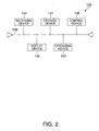
- Fig. 2 is a view of a schematic diagram showing a main hardware configuration of the positioning apparatus 100 show of Fig. 1.
- the positioning apparatus 100 has a computer.
- the computer includes a bus 105.
- a control device 106 such as a CPU (Central Processing Unit), for example, is connected to the bus 105.
- the receiving device 101, the display device 102, and the operating device 103 shown in Fig. 1 are also connected to the bus 105.
- the bus 105 is an internal bus having a function of connecting all devices and address and data paths.
- the control device 106 performs processing of predetermined programs and controls the storage device 107 connected to the bus 105 or the like.
- the storage device 107 stores various kinds of programs, various kinds of information, etc.
- Fig. 3 is a view of a schematic diagram showing a main software configuration of the positioning apparatus 100 of Fig. 1.
- the positioning apparatus 100 has a control unit 110 to control the entire positioning apparatus 100.
- the positioning apparatus 100 has a receiving unit 101a, a display unit 102a, and an operating unit 103a to manage the receiving device 101, the display device 102, and the operating device 103 of in Fig. 2, which are connected to the control unit 110. Accordingly, the receiving device 101, etc. are arranged to be controlled by the control unit 110.
- the positioning apparatus 100 has a positioning unit 111.
- the positioning unit 111 performs search of or locates the eight SPS satellites 10a to 10h shown in Fig. 1 or the like via the receiving unit 101a.
- the positioning unit 111 decodes satellite data from, for example, the four SPS satellites 10aa to 10dd chosen for positioning based on the DOP values, in a process which will be described later, from among all the SPS satellites 10a...., acquires navigation messages, and performs positioning calculation based on pseudo-range information to acquire position information of latitude, longitude, and altitude.
- the positioning unit 111 acquires position information by obtaining coordinates of an observation point and converting them into the coordinate system of latitude, longitude, and altitude.
- the positioning unit 111 is an example of a positioning device for acquire positioning information using SPS satellites 10a... selected based on satellite selection indicator information such as DOP values.
- the positioning result data of the positioning unit 111 are stored as positioning result data 135 in a second storage unit as shown in Fig. 3.
- the positioning apparatus 100 has a first storage unit 120 and the second storage unit 130 respectively connected to the control unit 110.
- SPS satellite data 131 are stored in the second storage unit 130.
- the SPS satellite data 131 are satellite location data of the SPS satellites 10a to 10h shown in Fig. 1 acquired based on the navigation message acquired by the positioning unit 111 or the like. Accordingly, the SPS satellite data 131 are an example of satellite location information.
- a DOP value calculation program 121 is stored in the first storage unit 120 in Fig. 3.
- the DOP value is an indicator expressing the relative location between the SPS satellites as shown in Fig. 9A and 9B.
- the smaller the DOP value the higher the positioning precision can be realized.
- the DOP value indicates by what number the error per unit is multiplied in the positioning result. Therefore, when the DOP value is small, the positioning precision is good, and, when the DOP value is large, the positioning precision is bad.
- the DOP value calculation program 121 selects a number of, for example four, SPS satellites 10aa to 10dd for positioning based on the SPS satellite data 131 of the second storage unit 130. Accordingly, the SPS satellites 10aa... for positioning are examples of the plural SPS used for positioning, the DOP values is an example of the satellite selection indicator information, and the DOP value calculation program 121 is an example of s satellite selection indicator information generating device. Specifically, for example, the DOP value calculation program 121 selects the four GPS satellites 10aa to 10dd for positioning as satellites capable of positioning precisely from among the acquired eight SPS satellites 10a to 10h shown in Fig. 1, based on the DOP values.
- DOP includes PDOP (Position DOP), VDOP (Vertical DOP), HDOP (Horizontal DOP), etc. and any of them can be used in the invention, however, in the present embodiment, the DOP value is calculated using PDOP, which represents position precision best.
- DOP value calculation result data 132 are stored in the second storage unit 130.
- DOP value caluculation result data 132 include the DOP values calculated by the DOP value calculation program 121 and data of the SPS satellites 10aa..., for positioning.
- a SPS satellite positioning mode evaluation program 122 is stored in the first storage unit 120.
- the SPS satellite positioning mode determination program 122 acquires electric wave data of the eight SPS satellites 10a to 10h, for example, from the GPS satellite data 131 of the second storage unit 130, and acquires electric wave reception environment information from the respective GPS satellites 10a...
- the reception environment information is expressed as mode information, outdoor mode or indoor mode, distinguished according to signal intensity from the eight SPS satellites 10a....
- mode information outdoor mode or indoor mode
- the outdoor mode is a mode in which the positioning apparatus 100 is located outdoors, for example, and signals from the SPS satellites 10a.... are received in a good condition. In this mode, since signals can be received in a good condition and noise level can be suppressed to a low level only when the signal intensity from the SPS satellites 10a ... is strong, the pseudo range is obtained and positioning is performed.
- the indoor mode is a mode in which the positioning apparatus 100 is located indoors, for example, and signals from the SPS satellites 10a.... are weak and can not be received in a good condition. In this mode, even when the signal intensity is generally weak, pseudo range is obtained and positioning is performed. In other words, the indoor mode is a mode provide to find signals from the SPS satellites 10a.... and to obtain a pseudo range even when positioning becomes difficult because the positioning can be performed only in the outdoor mode and the positioning apparatus 100 is located indoors.
- the SPS satellite positioning mode determination program 122 acquires signal data of the respective SPS satellites 10a.... from the SPS satellite data 131 of the second storage unit 130, analyses signal intensity, and determines whether each of the SPS satellites 10a, etc. is the outdoor mode or indoor mode according to the electric field intensity.
- SPS satellite positioning mode determination result data 133 as outdoor mode information or indoor mode information with respect to each of the SPS satellites 10a... determined in the SPS satellite positioning mode determination program 122 of the first storage unit 120 is stored as integral numbers or the like, for example.
- a DOP threshold value calculation program 123 is stored in the first storage unit 120.
- DOP threshold values are calculated based on the outdoor or indoor mode information with respect to each of the SPS satellites 10a... which is the SPS satellite positioning mode determination result data 133 of the second storage unit 130.
- the DOP threshold value calculation program 123 refers to DOP threshold value calculation table data 124 stored in the first storage unit 120 to calculate the DOP threshold values.
- Fig. 4 is a view of an example of a table showing DOP variable ratio values determined based on DOP threshold values 124. In the left column in Fig. 4, "number of indoor mode SPS satellites/number of located SPS satellites x 100(%)" is shown.
- the ratios of the number of the SPS satellites 10a ... in the indoor mode to the number of the SPS satellites 10a ... acquired by the positioning unit 111 in Fig. 3 are segmented in six stages. For example, when the total number of the acquired SPS satellites 10a... is eight, and the number of those SPS satellites 10a... which are in the indoor mode is zero, i.e., all of them are in the outdoor mode, the value becomes 0%.
- the right column in Fig. 4 shows variable ratios (%) of DOP threshold values and segmented in six stages as in the left column.
- the variable ratio (%) of DOP threshold value in the right column becomes 100%.
- all of the acquired SPS satellites 10a ... are in the outdoor mode, and is indicated, because the signal intensity that the positioning apparatus 100 receives from the GPS satellites 10a... is strong.
- the ratio of the number of indoor mode SPS satellites in the left column is 100%, the acquired SPS satellites 10a...
- the DOP ratio threshold value (%) in the right column is set to 50%. In this case, all of the above described values are half of those in the case of the outdoor mode. Accordingly, the positioning precision can be improved when the DOP value is small.
- the DOP threshold value calculation program 123 calculates using such a DOP threshold value calculation data table 124.
- the DOP threshold values are calculated based on the DOP ratio threshold values (%) in the right column in Fig. 4, for example, 100 % or 50% and the initial value.
- the DOP threshold value is calculated by taking "initial value x DOP ratio threshold value (%)".
- the initial value is a numeric value which allows DOP threshold values to correspond to DOP values, "10" for example.
- 10 (initial value) x 100(%) 10
- the DOP threshold value becomes "10".
- the DOP threshold value becomes smaller as the DOP threshold ratio (%) value becomes smaller, and the smaller DOP threshold value shows that the signal intensity from the SPS satellites 10a... received by the positioning apparatus 100 becomes weaker.
- the larger DOP threshold value shows that the intensity of signals from the SPS satellites 10a... received by the positioning apparatus 100 is strong. Therefore, the DOP threshold values are an example of information calculated based on the ratio of the outdoor mode or indoor mode SPS satellites 10a....
- the reception environment for electric waves of all the SPS satellites 10a... located by the positioning apparatus 100 can be shown in a simple and precise manner.
- the DOP threshold values calculated by the DOP threshold value calculation program 123 are stored in DOP threshold value calculation result data 134 of the second storage unit 130 shown in Fig. 3.
- the thus calculated DOP threshold values are values "from 10 to 5" as shown in Fig. 4, and these DOP threshold values are numeric values corresponding to DOP values. In other words, the DOP values also have values from 10 to 5. Therefore, the DOP threshold value calculation program 123 shown in Fig. 3 is an example of a reception environment indicator information generating device to generate reception environment indicator information (DOP threshold values or the like) that can be compared against DOP values with respect to positioning precision based on the mode information of signal intensity of electric waves from the SPS satellites 10a....
- the second storage unit 120 has a positioning result output/no output evaluation program 125.
- the positioning result output/no output evaluation program 125 compares a DOP value from the DOP value calculation result data 132 with a DOP threshold value as the DOP threshold value calculation result data 134 and determines whether the positioning result shall be output or not based on the DOP value.
- the positioning result output/no output evaluation program 125 is arranged to display positioning result data 135 on the display device 102 in the case where the DOP value is equal to or less than the DOP threshold value, for example. For example, when the DOP value is "8", and all of the SPS satellites 10a...
- the positioning result output/no output evaluation program 125 determines that the positioning result data 125 can be displayed because the DOP value "8" is less than the DOP threshold value "10".
- the DOP threshold value is set to as high as "10" in the table of Fig. 4 or the like, and, when the DOP value is equal to or less than "10", the positioning result data 135 are displayed.
- the DOP threshold value is set to as low as "5" from Fig. 4 or the like, and, when the DOP value is equal to or less than "5", i.e., only when the DOP value is good, the positioning result data 135 are displayed.
- the numeric value of the DOP threshold value is larger as the signal intensity is stronger, and smaller as the signal intensity is weaker from Fig. 4 or the like. For example, the numeric value is "10, 9, 8, 7, 6, 5".
- the positioning result output or not program 125 is an example of a positioning information evaluation device to determine whether the positioning result data 135 is to be outputted to the display device 102 or not, based on the DOP values and DOP threshold values.
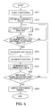
- FIG. 5 is a schematic flowchart showing a main operation example of the positioning apparatus 100 of the embodiment.
- a user of the positioning apparatus 100 shown in Fig. 1 operates the operating device 102, and thereby, positioning is started (ST1).
- the initial value when the DOP threshold value calculation program 123 of Fig. 3 performs a calculation based on the DOP threshold value calculation table data 124 is set.
- This initial value is a reference value for the DOP threshold value calculation program 123 in Fig. 3 to calculate a DOP threshold value that can be compared with a DOP value.
- a fixed value may be stored in the storage device 107 shown in Fig.2 in advance, or the user may be enabled to set an arbitrary value.
- an initial value for calculating a DOP threshold value comparable to a DOP value is set to "10" is described.
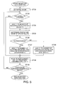
- FIG. 6 is a view of a schematic flowchart showing an operation example of the reception data analysis at ST3.
- initial value setting is performed (ST32).
- data of previous reception data analysis or the like are reset, and the initial value is once set to " 0" , for example.
- whether satellites have been located or not is determined (ST33).
- the positioning unit 111 in Fig. 3 determines whether the SPS satellites 10a... in Fig. 1 have been located or not.
- the positioning apparatus 100 has eight channels, and thereby, can track eight SPS satellites 10a.... Therefore, the positioning apparatus 100 performs the searching operation for the SPS satellites 10a... in the order from the first channel to the eighth channel.
- the positioning apparatus 100 executes an acquisition operation of the SPS satellites 10a... with respect to the first channel.
- the process moves to the next channel, i.e., the second channel and adds "1" to the processed channel counter (Ch) (ST39).
- the apparatus can locate the SPS satellite 10a, for example, in the first channel, it adds "1" to the number of acquired satellites (SV) (ST34).
- the SPS satellite positioning mode determination program 122 of the first storage unit 120 shown in Fig. 3 determines the mode.
- the result is stored in the second storage unit 130 as the SPS satellite positioning mode determination result data 133 shown in Fig. 3.
- the positioning mode of the SPS satellite 10a is determined (ST36).
- ST37 when the SPS satellite 10aa is in the outdoor mode, as shown in ST37, "1" is added to the number of acquired satellites in the outdoor mode (SVout).
- ST38 when the SPS satellite 10a is in the indoor mode, as shown in ST38, "1" is added to the number of acquired satellites in the indoor mode (SVin).
- ST39 moves to the next channel, i.e., the second channel and adds "1" to the processed channel counter (Ch).
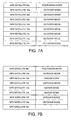
- Figs. 7A and 7B are tables showing analysis examples in which reception data analyses are thus performed.
- Fig. 7A shows the case where all of the SPS satellites 10a to 10h are in the outdoor mode.
- Fig. 7B shows the case where the SPS satellites 10a, 10c, 10f, and 10g are in the outdoor mode, the GPS satellites 10b, 10d, and 10e are in the indoor mode, and the SPS satellite 10h can not be acquired.
- data as in Figs. 7A and 7B is stored in the second storage unit 130 in Fig. 3 as the SPS satellite positioning mode determination result data 133.
- the DOP value is calculated (ST5) (an example of satellite selection indicator information generating step).
- the DOP value expressing the condition of the GPS satellites 10a... located at ST3 is determined.
- the DOP value calculation program 121 of the first storage unit 120 shown in Fig. 3 calculates the DOP value based on the SPS satellite data 131 of the second storage unit 130, and stores the calculation result as the DOP value calculation result data 132 in the second storage unit 130.
- the number of satellites (SV) acquired at ST3 is five or more, there are plural DOP values.
- the positioning apparatus 100 performs position calculation (ST6) (an example of positioning step).
- the control unit 110 in Fig. 3 selects the smallest DOP value from the DOP value calculation result data 132 in the second storage unit 130, and sets four SPS satellites 10a... corresponding to that DOP value as SPS satellites 10aa, 10bb, 10cc, and 10dd for positioning.
- the positioning unit 111 acquires the latitude, longitude, and altitude positioning information based on the navigation data of these four SPS satellites 10a... The position calculation is performed based on the navigation data, and thereby, the coordinates of an observation point in WGS84 geographic coordinate system are calculated.
- the coordinates are converted into a geographic coordinate system normally used in the observation point, for example, when the observation point is in Japan, they are converted into latitude, longitude, and altitude according to Japanese Geodetic Datum 2000.
- the DOP threshold value is determined (ST7) (an example of reception environment indicator information generating step).
- the DOP threshold value calculation program 123 shown in Fig. 3 determines the DOP threshold values based on the SPS satellite positioning mode determination result data 133 and the DOP threshold value calculation table (DOP value variable ratio table in Fig. 4) 124.
- Fig. 8 is a schematic flowchart showing an operation example of DOP threshold value determination. The operation example of DOP threshold value determination shown in Fig. 8 will be described based on the example in Fig. 7A or Fig. 7B.
- the ratio of indoor mode is calculated at ST72 in Fig. 8 (ST72). In other words, in the case of Fig.
- the ratio of indoor mode is calculated by 0/8 x 100 as 0% from the DOP value variable ratio table in Fig. 4.
- the ratio of indoor mode is calculated by 3/7 x 100 as about 42.8% from the DOP value variable ratio table in Fig. 4.
- the DOP ratio threshold value is acquired from the DOP value variable ratio table in Fig. 4 (ST7).
- the DOP ratio threshold value is "100%”.
- the DOP ratio threshold value is "80%”.
- the DOP threshold value is calculated (ST74).
- the positioning calculation result at ST6 is output, and, when the DOP value exceeds the DOP threshold value, the positioning calculation result at ST6 is not output (ST9) (an example of positioning information evaluation step and outputting step).
- the positioning result output/no output evaluation program 125 of the first storage unit 120 shown in Fig. 3 determines whether the DOP value of the DOP value calculation result data 132 of the second storage unit 130 is equal to or less than the DOP threshold value of the DOP threshold value calculation result data 134 or not.
- the display positioning result data 135 of the second storage unit 130 are displayed on the display device 102 via the display unit 102a. Specifically, in the case of Fig. 7A, when the DOP value is equal to or less than "10", the positioning result is output, and, in the case of Fig. 7B, only when the DOP value is equal to or less than "8", the positioning result is output.
- the DOP value is required to be smaller in Fig. 7B.
- the indoor mode satellites when the indoor mode satellites are included, there is a possibility that the electric wave signal intensity from the SPS satellites 10a.... has become weak and the positioning precision has deteriorated.
- the positioning precision has deteriorated.
- the positioning result in the condition in which the positioning precision has deteriorated is displayed on the display device 102, the reliability of the positioning apparatus 100 is decreased. Accordingly, in the present embodiment, a positioning result that possibly deteriorates the positioning precision is determined not to be output to the display device 102, and thereby, the precision of the positioning apparatus 100 is prevented from becoming lower.
- Fig. 7A in the case where the electric wave signal intensity from the SPS satellites 10a.... is strong, even when the DOP value is a value that is not output in Fig. 7B, there is a lower possibility that the positioning precision has deteriorated. Accordingly, in Fig. 7A, positioning results are output even when the DOP value is a value that is not output in Fig. 7B. Thus, depending to the quality level of the reception environment for signals from the SPS satellites 10a..., the positioning function evaluation reliability of the DOP value is varied, and only the positioning result with higher precision is displayed on the display device 102, and thereby, the reliability of the positioning apparatus 100 is improved.
- the DOP threshold values are calculated from the SPS satellites 10a.... actually used for positioning, and the reception environment for the electric wave signals from the SPS satellites 10aa.... for positioning can be grasped more accurately based on intensity of the signals.
- Positioning programs and the like for allowing a computer to execute the satellite selection indicator information generating step, the positioning step, outputting step, reception environment indicator information generating step, positioning information evaluation step, etc. in the above described operation example can be realized. Further, a computer readable recording medium in which such positioning program etc. are stored can also be realized.
- a program storage medium used for installing these positioning programs or the like in a computer and enabling them to be executed by the computer can be realized not only by package media such as a flexible disk or a floppy disk , CD-ROM (Compact Disc Read Only Memory), CD-R (Compact Disc-Recordable), CD-RW (Compact Disc-Rewritable), DVD (Digital Versatile Disc), for example, but also by a semiconductor memory, magnetic disk, magneto-optical disk, or the like in which programs are temporarily or permanently stored.
- package media such as a flexible disk or a floppy disk , CD-ROM (Compact Disc Read Only Memory), CD-R (Compact Disc-Recordable), CD-RW (Compact Disc-Rewritable), DVD (Digital Versatile Disc), for example, but also by a semiconductor memory, magnetic disk, magneto-optical disk, or the like in which programs are temporarily or permanently stored.
- the invention is not limited to the above described respective embodiments. Furthermore, the above described respective embodiments may be combined with one another. As used herein, the following directional terms "forward, rearward, above, downward, vertical, horizontal, below, and transverse" as well as ant other similar directional terms refer to those directions of a device equipped with the present invention. Accordingly, these terms, as utilized to describe the present invention should be interpreted relative to a device equipped with the present invention.
- the term "configured” as used herein to describe a component, section or part of a device includes hardware and/or software that is constructed and/or programmed to carry out the desired function.
Landscapes
- Engineering & Computer Science (AREA)
- Radar, Positioning & Navigation (AREA)
- Remote Sensing (AREA)
- Physics & Mathematics (AREA)
- General Physics & Mathematics (AREA)
- Computer Networks & Wireless Communication (AREA)
- Position Fixing By Use Of Radio Waves (AREA)
Abstract
Description
- The present invention relates to a positioning apparatus, a positioning method, a positioning program, and a computer-readable recording medium for recording a positioning program.
- Conventionally, a SPS (Satellite Positioning System) apparatus has been used as a positioning system for positioning using manmade satellites.
The SPS apparatus is constructed so as to determine its position by receiving signals from four satellites, for example. Specifically, the SPS apparatus performs positioning by selecting four SPS satellites from a large number of satellites located in the sky and receiving the signals therefrom.
However, when the four SPS satellites selected by the SPS apparatus are close to one another, sometimes positioning precision deteriorates due to influence of signal noise or the like.
Accordingly, in order to prevent the SPS apparatus from selecting such SPS satellites close to one another, DOP (Dilution Of Precision) values are used as shown in Japanese Patent Application Publication Hei-5-99680, especially Figure 5 thereof. Japanese Patent Application Publication Hei-5-99680 is herby incorporated by reference. - Fig. 9A and 9B of the instant disclosure is a schematic explanatory view of the DOP values. In other words, Fig. 9A is a schematic explanatory view showing an example of a small DOP value, and Fig. 9B is a schematic explanatory view showing an example of a large DOP value.
As shown in Fig. 9B, when the SPS apparatus selects SPS satellites S1 to S4 close to one another, the volume of a quadrangular pyramid formed by the four SPS satellites S1 to S4 becomes smaller and the DOP value becomes larger.
On the other hand, as shown in Fig. 9A, when the SPS apparatus selects SPS satellites S5 to S8 widely spaced from one another, the volume of a quadrangular pyramid formed by the four SPS satellites S5 to S8 becomes larger and the DOP value becomes smaller.
Therefore, the SPS apparatus can improve the positioning precision by selecting SPS satellites S5 etc. that make the DOP value smaller. - However, even when the SPS apparatus selects SPS satellites to make the DOP value smaller, in cases of an environment having poor reception conditions for electric waves received from the selected SPS satellites , the positioning precision becomes lower, even though the DOP value is small.
When the positioning precision worsens, reliability of the DOP value deteriorating becomes a problem. - In view of the above, it will be apparent to those skilled in the art from this disclosure that there exits a need for an improved a positioning apparatus, a positioning method, a positioning program, and a computer-readable recording medium for recording a positioning program. This invention addresses this need in the art as well as other needs, which will become apparatus to those skilled in the art from this disclosure.
- Therefore, it is an object of the present invention to provide a positioning apparatus, a positioning method, a positioning program, and a computer-readable recording medium for recording a positioning program that does not allow the positioning function evaluation reliability of satellite selection indicator information, such as DOP values, of SPS to deteriorate.
- According to a first aspect of the present invention, the aforementioned object isrealized by a positioning apparatus. The positioning apparatus includes a satellite selection indicator information generating device, a positioning device, and an outputting device. The satellite selection indicator information generating device generates satellite selection indicator information based on satellite location information of SPS located in the sky to select a plurality of the SPS used for positioning. The positioning device acquires positioning information using the plurality of SPS selected based on the satellite selection indicator information. The outputting device outputs the positioning information. The positioning apparatus is characterized a reception environment indicator information generating device. The reception environment indicator information generating device generates reception environment indicator information of the SPS that can be balanced against the satellite selection indicator information with respect to positioning precision. The positioning precision is calculated based on reception environment information contained in electric waves from the SPS. The positioning apparatus is also characterized by a positioning information evaluation device that determines whether the positioning information is to be output to the outputting device or not based on the satellite selection indicator information and the reception environment indicator information.
- According to the constitution of the apparatus of the first aspect of the present invention, the satellite selection indicator information generating device generates DOP values, for example, as satellite selection indicator information based on the satellite location information of SPS located in the sky. The DOP value expresses the size of the volume of a quadrangular pyramid formed by four of the SPS. Further, the larger the volume, the smaller the numeric value becomes. Regarding this numeric value, when the number of target SPS is five or more, for example, plural DOP values are obtained according to combinations of the SPS. For example, there are plural DOP values such as "10, 9, 8".
In the case of the DOP value, as shown in Figs.9A and 9B, the larger the volume, i.e., the smaller the numeric value, the more the positioning precision is improved. Thus, when the satellite selection indicator information is DOP, the satellite selection indicator information generating device generates the smallest DOP value, for example, "8" as the satellite selection indicator passing value.
The positioning device acquires latitude, longitude, and altitude information as the positioning information, using in this example the plural SPS corresponding to the DOP value "8" which is the satellite selection indicator passing value. - On the other hand, the reception environment indicator information generating device generates reception environment indicator information which can be balanced against the satellite selection indicator information with respect to positioning precision, calculated based on reception environment information contained in electric waves from the SPS, for example, information on degree of signal intensity of electric waves from the SPS.
In other words, the reception environment indicator information is information relating to the degree of signal intensity of electric waves from the SPS, for example, and displayed as values "from 10 to 5", for example, as threshold values that can be balanced against the DOP values.
In other words, the reception environment indicator information is information on the quality of the reception environment for electric waves from the SPS for which satellite selection indicator information has been calculated. Reception environment indicator information is expressed in numeric values, for example.
The reception environment indicator information can be balanced against the satellite selection indicator information with respect to positioning precision. In other words, the numeric values "from 10 to 5" are values that can be balanced against the DOP values by being set for example so that the smaller the value, the worse the environment of the reception condition is.
By the way, even when from the above plural DOP values "10, 9, 8", the four SPS with the smallest DOP value "8" are selected, and the positioning device performs positioning or the like accordingly, in the case where the electric waves from the SPS are received indoors or the like, the reception environment is bad, and thereby, even if the DOP value is small, the positioning precision is poor.
Accordingly, the positioning information evaluation device balances for example the DOP value "8", the satellite selection indicator value, against the numeric value "6", the reception environment indicator value, and determines whether the positioning information is to output to the outputting device or not. - Thus, according to the constitution of the present invention, whether to output the positioning information by the positioning device is determined by balancing the satellite selection indicator information such as DOP values against the reception environment indicator information given in numeric values, with respect to positioning precision.
Accordingly, unlike a conventional apparatus, there is never a case that when the positioning precision becomes worse because the reception environment for electric waves from the SPS selected based on the satellite selection indicator information such as DOP values, the positioning information is output to the outputting device without change.
Therefore, the positioning precision of the positioning apparatus can be prevented from becoming worse, and the positioning function evaluation reliability of the satellite selection indicator information can be prevented from deteriorating. - An apparatus according to a second aspect of the present invention is the apparatus of the first aspect , wherein the SPS for which the reception environment indicator information generating device generates reception environment indicator passing values are the plurality of SPS used for the positioning.
- According to the constitution of the apparatus of the second aspect of the present invention, since the reception environment indicator information generating device generates the reception environment indicator information on the plural SPS used for the positioning, the reception environment condition of electric waves from the SPS selected based on the satellite selection indicator information such as DOP values can be grasped more accurately.
Accordingly, since output of the positioning information can be performed more precisely, the positioning function evaluation reliability of the satellite selection indicator information can be prevented from deteriorating and be more stable. - An apparatus, according to a third aspect of the present invention is the apparatus of the first or second aspect, wherein the reception environment indicator information is reception environment threshold value information, and the satellite selection indicator information is DOP value information representing a location status of the SPS.
- According to the constitution of the apparatus of the third aspect of the present invention, the reception environment indicator information is reception environment threshold value information. For example, the reception environment indicator information is threshold values "from 10 to 5". Further, the lower the threshold value, the worse the reception environment becomes.
On the other hand, the DOP value used as the satellite selection indicator value is not affected by the reception environment. When the locations of the SPS are preferable, the DOP value becomes lower, and if the locations are not desirable, the DOP value becomes higher.
Further, in comparison between the cases of "10" and "7", for example, the positioning precision sometimes becomes better in the case of "10", the higher DOP value, than the case of "7", the lower DOP value, because of reception environment difference. The deterioration in positioning precision cannot be determined by the DOP values only.
However, in the present invention, the reception environment indicator information is expressed in threshold values "from 10 to 5", for example, as information which can be balanced against the DOP values with respect to the positioning precision.
Accordingly, the degree of deterioration in reception environment can be expressed by the threshold values "from 10 to 5". Therefore, by comparing the threshold values with DOP values, the influence of the reception environment, which deteriorates the positioning function evaluation reliability of the DOP values, can be determined in a simple and precise manner. - An apparatus according to a fourth aspect of the present invention is the apparatus of any of the first three aspect, wherein the reception environment indicator information is in an outdoor mode in which signal intensity from the SPS is strong or in an indoor mode in which signal intensity from the SPS is weak, each of the position information satellites are in either the outdoor mode or the indoor mode, and the reception environment indicator information is information based on the ratio of the SPS in the outdoor mode or the indoor mode.
- According to the constitution of apparatus of the fourth aspect of the present invention, since the reception environment information of each SPS is expressed as "outdoor mode" or "indoor mode" representing signal intensity, the signal intensity can be grasped easily.
Further, the reception environment indicator information is formed based on the ratio of all the SPS in the outdoor mode and all those in the indoor mode. Accordingly, the reception environment indicator information of the SPS selected according to the satellite selection indicator information can be generated in a simple and precise manner. - A positioning method according to a fifth aspect of the present invention includes a satellite selection indicator information generating step at which a satellite selection indicator information generating device of a positioning apparatus generates satellite selection indicator information based on satellite location information of SPS located in the sky, to select a plurality of the SPS used for positioning; a positioning step at which a positioning device of the positioning apparatus acquires positioning information using the plurality of SPS selected based on the satellite selection indicator information; and an outputting step at which an outputting device of the positioning apparatus outputs the positioning information. The positioning method is characterized by : a reception environment indicator information generating step at which a reception environment indicator information generating device of the positioning apparatus generates reception environment indicator information of the SPS which can be balanced against the satellite selection indicator information with respect to positioning precision, which is calculated based on reception environment information contained in electric waves from the SPS; and a positioning information evaluation step at which a positioning information evaluation device of the positioning apparatus determines whether the positioning information is to be output to the outputting device or not based on the satellite selection indicator information and the reception environment indicator information.
- According to the constitution of the method of the fifth aspect of present invention, similar to the constitution of apparataus of the first aspect, whether to output the positioning information generated by the positioning device is determined by balancing the satellite selection indicator information such as DOP values against the reception environment indicator information, given in numeric values, with respect to positioning precision.
Accordingly, unlike a conventional method, there is never a case that when the positioning precision worsens because of the reception environment for electric waves from the SPS selected based on the satellite selection indicator information such as DOP values, the positioning information is output to the outputting device without a change.
Therefore, the positioning precision can be prevented from becoming worse, and the positioning function evaluation reliability of the satellite selection indicator information can be prevented from deteriorating. - The aforementioned object of the present invention is realized according to a sixth aspect of the present invention by a positioning program. The positioning program allows a computer to execute: a satellite selection indicator information generating step at which a satellite selection indicator information generating device of a positioning apparatus generates satellite selection indicator information, based on satellite location information of SPS located in the skyto select a plurality of the SPS used for positioning; a positioning step at which a positioning device of the positioning apparatus acquires positioning information using the plurality of SPS selected based on the satellite selection indicator information; and an outputting step at which an outputting device of the positioning apparatus outputs the positioning information. The positioning method is characterized by : a reception environment indicator information generating step at which a reception environment indicator information generating device of the positioning apparatus generates reception environment indicator information of the SPS which can be balanced against the satellite selection indicator information with respect to positioning precision, which is calculated based on reception environment information contained in electric waves from the SPS; and a positioning information evaluation step at which a positioning information evaluation device of the positioning apparatus determines whether the positioning information is to be output to the outputting device or not based on the satellite selection indicator information and the reception environment indicator information.
- According to the program of sixth aspect of the present invention, similar to the apparatus of the first aspect of the present invention, the positioning function evaluation reliability of the satellite selection indicator information can be prevented from deteriorating.
- The aforementioned object is realized according to a seventh aspect of the present invention by a positioning program. The positioning program allows a computer-readable recording medium to record a positioning program to allow a computer to execute the following: a satellite selection indicator information generating step at which a satellite selection indicator information generating device of a positioning apparatus generates satellite selection indicator information based on satellite location information of SPS located in the sky to select a plurality of SPS to be used for positioning; a positioning step at which a positioning device of the positioning apparatus acquires positioning information using the plurality of SPS selected based on the satellite selection indicator information; and an outputting step at which an outputting device of the positioning apparatus outputs the positioning information. The positioning program is characterized by : a reception environment indicator information generating step at which a reception environment indicator information generating device of the positioning apparatus generates reception environment indicator information of the SPS which can be balanced against the satellite selection indicator information with respect to positioning precision, which is calculated based on reception environment information contained in electric waves from the SPS; and a positioning information evaluation step at which a positioning information evaluation device of the positioning apparatus determines whether the positioning information is to be output to the outputting device or not based on the satellite selection indicator information and the reception environment indicator information.
- According to the program of the seventh aspect of the present invention, similar to the apparatus of the first aspect, the positioning function evaluation reliability of the satellite selection indicator information never deteriorates
These and other objects, features, aspects, and advantages of the present invention will become apparent to those skilled in the art from the following detailed description, which, taken in conjunction with the annexed drawing, discloses a preferred embodiment of the present invention. - Referring now to the attached drawings which form a part of this original disclosure:
- Fig. 1
- is a view of a schematic diagram showing a positioning apparatus according to a first preferred embodiment of the present invention.
- Fig. 2
- is a view of a schematic diagram showing a configuration of main hardware parts in the positioning apparatus in Fig. 1.
- Fig. 3
- is a view of a schematic diagram showing the configuration of the main software in the positioning apparatus in Fig. 1.
- Fig. 4
- is a view of a schematic DOP value variable ratio - DOP threshold value calculation table example.
- Fig. 5
- is a view of a schematic flowchart showing a main operation example of the positioning apparatus according to the first embodiment.
- Fig. 6
- is a view of a schematic flowchart showing an operation example of reception data analysis shown in Fig.5.
- Fig. 7A and 7B
- are view of tables showing analysis examples on which reception data analysis is performed.
- Fig. 8
- is a view of a schematic flowchart showing an operation example of DOP threshold value determination.
- Fig. 9
- is a view of a schematic explanatory view of DOP values.
- Selected embodiments of the present invention will now be explained with reference to the drawing. It will be apparent to those skilled in the art from this disclosure that the following descriptions of the embodiments of the present invention are provided for illustration only and not for the purpose of limiting the invention as defined by the appended claims and their equivalents.
- Hereinafter, a preferred embodiment of the invention will be described in detail by referring to accompanying drawings etc.
Since the embodiment as described below is a preferred specific example of the invention, technically preferred various limitations are imposed thereon; however, the scope of the invention is not limited to the modes in the explanations below unless there is a clause that specifically limits the invention. - Fig. 1 is a view of a schematic diagram showing a
positioning apparatus 100 according to a first preferred embodiment of the present invention. Thepositioning apparatus 100 shown in Fig. 1 is constructed to determine its own position with regard e.g. to latitude, longitude, and altitude, by SPS for example.
Accordingly, thepositioning apparatus 100 has a receivingdevice 101 including an antenna or the like for receiving electric waves transmitted from SPS located in the sky, such asSPS satellites 10a....
In a concrete example, thepositioning apparatus 100 locates eightSPS satellites 10a to 10h, selects four of them, 10aa, 10bb, 10cc, and 10dd, for positioning as described below, and performs positioning.
Further, thepositioning apparatus 100 has adisplay device 102 as a display, for example, to output and to display positioning information. Accordingly, thedisplay device 102 is an example of outputting device.
A user of thepositioning apparatus 100 can confirm the positioning result by viewing the positioning information displayed on thedisplay device 102.
The output device includes not only thedisplay device 102 of the present embodiment, but also a construction to transmit positioning results to an external server or the like using a communication device (not shown).
Further, thepositioning apparatus 100 has anoperating device 103 for the user to input information or the like including a numeric keypad or the like, for example. - Fig. 2 is a view of a schematic diagram showing a main hardware configuration of the
positioning apparatus 100 show of Fig. 1. As shown in Fig. 2, thepositioning apparatus 100 has a computer. In other words, the computer includes abus 105. Further, acontrol device 106 such as a CPU (Central Processing Unit), for example, is connected to thebus 105.
Moreover, astorage device 107 including a RAM (Random Access Memory) or ROM (Read Only Memory) is also connected to thebus 105.
Furthermore, the receivingdevice 101, thedisplay device 102, and theoperating device 103 shown in Fig. 1 are also connected to thebus 105. - In other Words, the
bus 105 is an internal bus having a function of connecting all devices and address and data paths. Thecontrol device 106 performs processing of predetermined programs and controls thestorage device 107 connected to thebus 105 or the like. Thestorage device 107 stores various kinds of programs, various kinds of information, etc. - Fig. 3 is a view of a schematic diagram showing a main software configuration of the
positioning apparatus 100 of Fig. 1. As shown in Fig. 3, thepositioning apparatus 100 has acontrol unit 110 to control theentire positioning apparatus 100.
Further, thepositioning apparatus 100 has a receivingunit 101a, adisplay unit 102a, and anoperating unit 103a to manage the receivingdevice 101, thedisplay device 102, and theoperating device 103 of in Fig. 2, which are connected to thecontrol unit 110.
Accordingly, the receivingdevice 101, etc. are arranged to be controlled by thecontrol unit 110. - Further, the
positioning apparatus 100 has apositioning unit 111. Thepositioning unit 111 performs search of or locates the eightSPS satellites 10a to 10h shown in Fig. 1 or the like via the receivingunit 101a. - Further, the
positioning unit 111 decodes satellite data from, for example, the four SPS satellites 10aa to 10dd chosen for positioning based on the DOP values, in a process which will be described later, from among all theSPS satellites 10a...., acquires navigation messages, and performs positioning calculation based on pseudo-range information to acquire position information of latitude, longitude, and altitude.
In other words, thepositioning unit 111 acquires position information by obtaining coordinates of an observation point and converting them into the coordinate system of latitude, longitude, and altitude. Accordingly, thepositioning unit 111 is an example of a positioning device for acquire positioning information usingSPS satellites 10a... selected based on satellite selection indicator information such as DOP values.
Then, the positioning result data of thepositioning unit 111 are stored as positioningresult data 135 in a second storage unit as shown in Fig. 3. - As shown in Fig. 3, the
positioning apparatus 100 has afirst storage unit 120 and thesecond storage unit 130 respectively connected to thecontrol unit 110.
SPS satellite data 131 are stored in thesecond storage unit 130. TheSPS satellite data 131 are satellite location data of theSPS satellites 10a to 10h shown in Fig. 1 acquired based on the navigation message acquired by thepositioning unit 111 or the like. Accordingly, theSPS satellite data 131 are an example of satellite location information. - Further, a DOP
value calculation program 121 is stored in thefirst storage unit 120 in Fig. 3. The DOP value is an indicator expressing the relative location between the SPS satellites as shown in Fig. 9A and 9B. The smaller the DOP value, the higher the positioning precision can be realized.
Specifically, at the time of positioning, when there is an error in the pseudo range from the SPS satellite with a given error value per set unit of distance, the DOP value indicates by what number the error per unit is multiplied in the positioning result. Therefore, when the DOP value is small, the positioning precision is good, and, when the DOP value is large, the positioning precision is bad. - The DOP
value calculation program 121 selects a number of, for example four, SPS satellites 10aa to 10dd for positioning based on theSPS satellite data 131 of thesecond storage unit 130.
Accordingly, the SPS satellites 10aa... for positioning are examples of the plural SPS used for positioning, the DOP values is an example of the satellite selection indicator information, and the DOPvalue calculation program 121 is an example of s satellite selection indicator information generating device.
Specifically, for example, the DOPvalue calculation program 121 selects the four GPS satellites 10aa to 10dd for positioning as satellites capable of positioning precisely from among the acquired eightSPS satellites 10a to 10h shown in Fig. 1, based on the DOP values. - Further, DOP includes PDOP (Position DOP), VDOP (Vertical DOP), HDOP (Horizontal DOP), etc. and any of them can be used in the invention, however, in the present embodiment, the DOP value is calculated using PDOP, which represents position precision best.
Further, still referring to in Fig. 3, DOP value calculation resultdata 132 are stored in thesecond storage unit 130. DOP valuecaluculation result data 132 include the DOP values calculated by the DOPvalue calculation program 121 and data of the SPS satellites 10aa..., for positioning. - Further, a SPS satellite positioning
mode evaluation program 122 is stored in thefirst storage unit 120.
In other words, the SPS satellite positioningmode determination program 122 acquires electric wave data of the eightSPS satellites 10a to 10h, for example, from theGPS satellite data 131 of thesecond storage unit 130, and acquires electric wave reception environment information from therespective GPS satellites 10a... - Specifically, the reception environment information is expressed as mode information, outdoor mode or indoor mode, distinguished according to signal intensity from the eight
SPS satellites 10a.... In other words, when the signal intensity from therespective SPS satellites 10a.... is strong, the information is in the outdoor mode, and contrary, when the signal intensity is weak, the information is in the indoor mode.
The outdoor mode is a mode in which thepositioning apparatus 100 is located outdoors, for example, and signals from theSPS satellites 10a.... are received in a good condition. In this mode, since signals can be received in a good condition and noise level can be suppressed to a low level only when the signal intensity from theSPS satellites 10a ... is strong, the pseudo range is obtained and positioning is performed. - On the other hand, the indoor mode is a mode in which the
positioning apparatus 100 is located indoors, for example, and signals from theSPS satellites 10a.... are weak and can not be received in a good condition. In this mode, even when the signal intensity is generally weak, pseudo range is obtained and positioning is performed.
In other words, the indoor mode is a mode provide to find signals from theSPS satellites 10a.... and to obtain a pseudo range even when positioning becomes difficult because the positioning can be performed only in the outdoor mode and thepositioning apparatus 100 is located indoors. - Still referring to Fig.3,as described above, the SPS satellite positioning
mode determination program 122 acquires signal data of therespective SPS satellites 10a.... from theSPS satellite data 131 of thesecond storage unit 130, analyses signal intensity, and determines whether each of theSPS satellites 10a, etc. is the outdoor mode or indoor mode according to the electric field intensity.
In thesecond storage unit 130 , SPS satellite positioning mode determination resultdata 133 as outdoor mode information or indoor mode information with respect to each of theSPS satellites 10a... determined in the SPS satellite positioningmode determination program 122 of thefirst storage unit 120 is stored as integral numbers or the like, for example. - Further, as shown in Fig. 3, a DOP threshold
value calculation program 123 is stored in thefirst storage unit 120. In other words, DOP threshold values are calculated based on the outdoor or indoor mode information with respect to each of theSPS satellites 10a... which is the SPS satellite positioning mode determination resultdata 133 of thesecond storage unit 130.
Specifically, the DOP thresholdvalue calculation program 123 refers to DOP threshold valuecalculation table data 124 stored in thefirst storage unit 120 to calculate the DOP threshold values.
Fig. 4 is a view of an example of a table showing DOP variable ratio values determined based on DOP threshold values 124.
In the left column in Fig. 4, "number of indoor mode SPS satellites/number of located SPS satellites x 100(%)" is shown. In other words, the ratios of the number of theSPS satellites 10a ... in the indoor mode to the number of theSPS satellites 10a ... acquired by thepositioning unit 111 in Fig. 3 are segmented in six stages.
For example, when the total number of the acquiredSPS satellites 10a... is eight, and the number of thoseSPS satellites 10a... which are in the indoor mode is zero, i.e., all of them are in the outdoor mode, the value becomes 0%. - The right column in Fig. 4 shows variable ratios (%) of DOP threshold values and segmented in six stages as in the left column. For example, when the ratio of number of indoor mode SPS satellites in the left column is 0%, the variable ratio (%) of DOP threshold value in the right column becomes 100%.
In this case, all of the acquiredSPS satellites 10a ... are in the outdoor mode, and is indicated, because the signal intensity that thepositioning apparatus 100 receives from theGPS satellites 10a... is strong. Thus, even when the DOP value is large, the positioning precision is improved.
On the other hand, when the ratio of the number of indoor mode SPS satellites in the left column is 100%, the acquiredSPS satellites 10a... are in the indoor mode and the signal intensity that the positioning apparatus receives from theSPS satellites 10a.... is extremely weak. Accordingly, the DOP ratio threshold value (%) in the right column is set to 50%.
In this case, all of the above described values are half of those in the case of the outdoor mode. Accordingly, the positioning precision can be improved when the DOP value is small. - The DOP threshold
value calculation program 123 calculates using such a DOP threshold value calculation data table 124.
Specifically, the DOP threshold values are calculated based on the DOP ratio threshold values (%) in the right column in Fig. 4, for example, 100 % or 50% and the initial value. Specifically, the DOP threshold value is calculated by taking "initial value x DOP ratio threshold value (%)".
The initial value is a numeric value which allows DOP threshold values to correspond to DOP values, "10" for example.
As described above, when the ratio of the number of indoor mode SPS satellites is 0% and thus the variable ratio (%) of DOP threshold value is 100%, 10 (initial value) x 100(%) = 10, and the DOP threshold value becomes "10".
Further, when the ratio of the number of indoor mode SPS satellites is 100% and the variable ratio (%) of DOP threshold value is 50%, 10 (initial value) x 50(%) = 5, and the DOP threshold value becomes "5".
Thus, the DOP threshold value becomes smaller as the DOP threshold ratio (%) value becomes smaller, and the smaller DOP threshold value shows that the signal intensity from theSPS satellites 10a... received by thepositioning apparatus 100 becomes weaker.
Conversely, the larger DOP threshold value shows that the intensity of signals from theSPS satellites 10a... received by thepositioning apparatus 100 is strong.
Therefore, the DOP threshold values are an example of information calculated based on the ratio of the outdoor mode or indoormode SPS satellites 10a....
In the method described above, by setting the DOP threshold values based on the ratio of the outdoor mode or indoor mode for each of theSPS satellites 10a..., the reception environment for electric waves of all theSPS satellites 10a... located by thepositioning apparatus 100 can be shown in a simple and precise manner. - Thus, the DOP threshold values calculated by the DOP threshold
value calculation program 123 are stored in DOP threshold value calculation resultdata 134 of thesecond storage unit 130 shown in Fig. 3.
The thus calculated DOP threshold values are values "from 10 to 5" as shown in Fig. 4, and these DOP threshold values are numeric values corresponding to DOP values. In other words, the DOP values also have values from 10 to 5.
Therefore, the DOP thresholdvalue calculation program 123 shown in Fig. 3 is an example of a reception environment indicator information generating device to generate reception environment indicator information (DOP threshold values or the like) that can be compared against DOP values with respect to positioning precision based on the mode information of signal intensity of electric waves from theSPS satellites 10a.... - Further, as shown in Fig. 3, the
second storage unit 120 has a positioning result output/nooutput evaluation program 125. The positioning result output/nooutput evaluation program 125 compares a DOP value from the DOP value calculation resultdata 132 with a DOP threshold value as the DOP threshold value calculation resultdata 134 and determines whether the positioning result shall be output or not based on the DOP value.
Specifically, the positioning result output/nooutput evaluation program 125 is arranged to display positioningresult data 135 on thedisplay device 102 in the case where the DOP value is equal to or less than the DOP threshold value, for example.
For example, when the DOP value is "8", and all of theSPS satellites 10a... acquired by thepositioning unit 111 are in the outdoor mode and the reception environment is good, and the DOP threshold value as the reception environment threshold value is "10", the positioning result output/nooutput evaluation program 125 determines that thepositioning result data 125 can be displayed because the DOP value "8" is less than the DOP threshold value "10". - In other words, in the case where the signal intensity from the
SPS satellites 10a... is strong and all of them are in the outdoor mode, it is highly possible that positioning can be performed with precision even when the DOP value is high. Accordingly, the DOP threshold value is set to as high as "10" in the table of Fig. 4 or the like, and, when the DOP value is equal to or less than "10", thepositioning result data 135 are displayed. - On the other hand, in the case where the signal intensity from the
SPS satellites 10a... is weak and all of them are in the indoor mode, it is scarcely possible that positioning can be performed with precision when the DOP value is high. Accordingly, the DOP threshold value is set to as low as "5" from Fig. 4 or the like, and, when the DOP value is equal to or less than "5", i.e., only when the DOP value is good, thepositioning result data 135 are displayed.
Further, the numeric value of the DOP threshold value is larger as the signal intensity is stronger, and smaller as the signal intensity is weaker from Fig. 4 or the like. For example, the numeric value is "10, 9, 8, 7, 6, 5".
Thus, as the signal intensity of the entire eightSPS satellites 10a... acquired by thepositioning apparatus 100 becomes weaker, the DOP value required for the positioning becomes lower in stages. - In other words, the positioning result output or not
program 125 is an example of a positioning information evaluation device to determine whether thepositioning result data 135 is to be outputted to thedisplay device 102 or not, based on the DOP values and DOP threshold values. - The
positioning apparatus 100 according to the present invention is constructed as above, and an operation example etc. thereof will be described as below.
Regarding main operation example ofpositioning apparatus 100
Fig. 5 is a schematic flowchart showing a main operation example of thepositioning apparatus 100 of the embodiment.
First, a user of thepositioning apparatus 100 shown in Fig. 1 operates theoperating device 102, and thereby, positioning is started (ST1).
Then, at ST2, the initial value when the DOP thresholdvalue calculation program 123 of Fig. 3 performs a calculation based on the DOP threshold valuecalculation table data 124 is set. This initial value is a reference value for the DOP thresholdvalue calculation program 123 in Fig. 3 to calculate a DOP threshold value that can be compared with a DOP value.
As to the initial value, a fixed value may be stored in thestorage device 107 shown in Fig.2 in advance, or the user may be enabled to set an arbitrary value. In this embodiment, an example in which an initial value for calculating a DOP threshold value comparable to a DOP value is set to "10" is described. - Then, at ST3, reception data analysis is performed. Fig. 6 is a view of a schematic flowchart showing an operation example of the reception data analysis at ST3.
As shown in Fig. 6, first, initial value setting is performed (ST32). In other words, data of previous reception data analysis or the like are reset, and the initial value is once set to " 0" , for example.
Then, whether satellites have been located or not is determined (ST33). In other words, thepositioning unit 111 in Fig. 3 determines whether theSPS satellites 10a... in Fig. 1 have been located or not. In the embodiment, thepositioning apparatus 100 has eight channels, and thereby, can track eightSPS satellites 10a....
Therefore, thepositioning apparatus 100 performs the searching operation for theSPS satellites 10a... in the order from the first channel to the eighth channel. - First, the
positioning apparatus 100 executes an acquisition operation of theSPS satellites 10a... with respect to the first channel. When the apparatus cannot locate theSPS satellites 10a in the first channel, the process moves to the next channel, i.e., the second channel and adds "1" to the processed channel counter (Ch) (ST39).
On the other hand, when the apparatus can locate theSPS satellite 10a, for example, in the first channel, it adds "1" to the number of acquired satellites (SV) (ST34).
Then, whether theSPS satellite 10a is in the indoor mode or outdoor mode is determined from the signal intensity of the electric wave from the acquiredSPS satellite 10a (ST35). Specifically, the SPS satellite positioningmode determination program 122 of thefirst storage unit 120 shown in Fig. 3 determines the mode.
Then, the result is stored in thesecond storage unit 130 as the SPS satellite positioning mode determination resultdata 133 shown in Fig. 3. - Then, the positioning mode of the
SPS satellite 10a is determined (ST36). In other words, when the SPS satellite 10aa is in the outdoor mode, as shown in ST37, "1" is added to the number of acquired satellites in the outdoor mode (SVout).
On the other hand, when theSPS satellite 10a is in the indoor mode, as shown in ST38, "1" is added to the number of acquired satellites in the indoor mode (SVin).
Thus, the process is ended with respect to the first channel, and, as shown in ST39, moves to the next channel, i.e., the second channel and adds "1" to the processed channel counter (Ch). - Then, whether the number of processed channels is "8" or not, In other words, whether processing is ended with respect to all of the eight channels or not is determined (ST40), and the same operation is repeated from the first channel to the eighth channel until the processing is ended.
- Figs. 7A and 7B are tables showing analysis examples in which reception data analyses are thus performed. Fig. 7A shows the case where all of the
SPS satellites 10a to 10h are in the outdoor mode.
Fig. 7B shows the case where theSPS satellites GPS satellites SPS satellite 10h can not be acquired.
In other words, data as in Figs. 7A and 7B is stored in thesecond storage unit 130 in Fig. 3 as the SPS satellite positioning modedetermination result data 133. - As shown in Fig.5, when the reception data analysis (ST3) is ended as described above, whether the number of located satellites (SV) is equal to or more than "4" or not is determined (ST4) .
In order to obtain latitude, longitude, and altitude as positioning information by single positioning using the SPS, searching of or locating at least fourSPS satellites 10a... is required.
However, since the positioning (two-dimensional positioning) can be performed by performing calculation on the assumption that one of theSPS satellites 10a... is located at the center of an ellipsoid even when only three of theSPS satellites 10a... can be located, it is sufficient that it be determined whether three ormore SPS satellites 10a... can be located, unlike this embodiment.
In the present embodiment, when four or more are not located, it is determined that positioning is impossible, and performs reception data analysis by returning to ST 3. - On the other hand, when the number of located satellites (SV) is four or more, the DOP value is calculated (ST5) (an example of satellite selection indicator information generating step). In other words, the DOP value expressing the condition of the
GPS satellites 10a... located at ST3 is determined. Specifically, the DOPvalue calculation program 121 of thefirst storage unit 120 shown in Fig. 3 calculates the DOP value based on theSPS satellite data 131 of thesecond storage unit 130, and stores the calculation result as the DOP value calculation resultdata 132 in thesecond storage unit 130.
When the number of satellites (SV) acquired at ST3 is five or more, there are plural DOP values. - Then, the
positioning apparatus 100 performs position calculation (ST6) (an example of positioning step). In other words, thecontrol unit 110 in Fig. 3 selects the smallest DOP value from the DOP value calculation resultdata 132 in thesecond storage unit 130, and sets fourSPS satellites 10a... corresponding to that DOP value as SPS satellites 10aa, 10bb, 10cc, and 10dd for positioning.
Then, thepositioning unit 111 acquires the latitude, longitude, and altitude positioning information based on the navigation data of these fourSPS satellites 10a... The position calculation is performed based on the navigation data, and thereby, the coordinates of an observation point in WGS84 geographic coordinate system are calculated.
In the present embodiment, to make the display easier to understand for users, the coordinates are converted into a geographic coordinate system normally used in the observation point, for example, when the observation point is in Japan, they are converted into latitude, longitude, and altitude according to Japanese Geodetic Datum 2000. - Then, the DOP threshold value is determined (ST7) (an example of reception environment indicator information generating step). In other words, the DOP threshold
value calculation program 123 shown in Fig. 3 determines the DOP threshold values based on the SPS satellite positioning mode determination resultdata 133 and the DOP threshold value calculation table (DOP value variable ratio table in Fig. 4) 124.
Fig. 8 is a schematic flowchart showing an operation example of DOP threshold value determination. The operation example of DOP threshold value determination shown in Fig. 8 will be described based on the example in Fig. 7A or Fig. 7B.
First, the ratio of indoor mode is calculated at ST72 in Fig. 8 (ST72). In other words, in the case of Fig. 7A, since all of the acquiredSPS satellites 10a.... are in the outdoor mode, the ratio of indoor mode is calculated by 0/8 x 100 as 0% from the DOP value variable ratio table in Fig. 4.
On the other hand, in the case of Fig. 7B, because three of the acquiredSPS satellites 10a.... are in the indoor mode, the ratio of indoor mode is calculated by 3/7 x 100 as about 42.8% from the DOP value variable ratio table in Fig. 4. - Then, the DOP ratio threshold value is acquired from the DOP value variable ratio table in Fig. 4 (ST7). In other words, in the case of Fig. 7A, since the numeric value in the left column in Fig. 4 is "0%", the DOP ratio threshold value is "100%".
Further, in the case of Fig. 7B, because the numeric value in the left column in Fig. 4 is "42.8%", the DOP ratio threshold value is "80%". - Then, the DOP threshold value is calculated (ST74). In other words, the DOP threshold
value calculation program 123 in Fig. 3 calculates the DOP threshold value where "10" is the initial value set at ST2.
Specifically, in the case of Fig. 7A, from 10 x 100% = 10, the DOP threshold value is " 10" .
On the other hand, in the case of Fig. 7B, from 10 x 80% = 8, the DOP threshold value is " 8" .
Thus, the DOP threshold value is calculated and the DOP threshold value determining step in Fig. 5 is ended. - Then, whether the DOP value calculated at ST5 is equal to or less than the DOP threshold value calculated at ST7 or not is determined (ST8). When the DOP value is equal to or less than the DOP threshold value, the positioning calculation result at ST6 is output, and, when the DOP value exceeds the DOP threshold value, the positioning calculation result at ST6 is not output (ST9) (an example of positioning information evaluation step and outputting step).
In other words, the positioning result output/nooutput evaluation program 125 of thefirst storage unit 120 shown in Fig. 3 determines whether the DOP value of the DOP value calculation resultdata 132 of thesecond storage unit 130 is equal to or less than the DOP threshold value of the DOP threshold value calculation resultdata 134 or not. Only when the DOP value is equal to or less than the DOP threshold value, the displaypositioning result data 135 of thesecond storage unit 130 are displayed on thedisplay device 102 via thedisplay unit 102a.
Specifically, in the case of Fig. 7A, when the DOP value is equal to or less than "10", the positioning result is output, and, in the case of Fig. 7B, only when the DOP value is equal to or less than "8", the positioning result is output. - Thus, according to the present embodiment, in comparison between Fig. 7A and Fig. 7B, the DOP value is required to be smaller in Fig. 7B. In other words, as shown in Fig. 7B, when the indoor mode satellites are included, there is a possibility that the electric wave signal intensity from the
SPS satellites 10a.... has become weak and the positioning precision has deteriorated.
Further, when positioning is performed with the large DOP value in spite of the fact that the signal intensity is weak, there is a possibility that the positioning precision has deteriorated. When the positioning result in the condition in which the positioning precision has deteriorated is displayed on thedisplay device 102, the reliability of thepositioning apparatus 100 is decreased.
Accordingly, in the present embodiment, a positioning result that possibly deteriorates the positioning precision is determined not to be output to thedisplay device 102, and thereby, the precision of thepositioning apparatus 100 is prevented from becoming lower. - Further, as in Fig. 7A, in the case where the electric wave signal intensity from the
SPS satellites 10a.... is strong, even when the DOP value is a value that is not output in Fig. 7B, there is a lower possibility that the positioning precision has deteriorated. Accordingly, in Fig. 7A, positioning results are output even when the DOP value is a value that is not output in Fig. 7B.
Thus, depending to the quality level of the reception environment for signals from theSPS satellites 10a..., the positioning function evaluation reliability of the DOP value is varied, and only the positioning result with higher precision is displayed on thedisplay device 102, and thereby, the reliability of thepositioning apparatus 100 is improved. - Further, as in the present embodiment, when the SPS satellites 10aa... actually used by the
positioning unit 111 for positioning are included in theSPS satellites 10a... as targets for the SPS satellite positioningmode determination program 122 shown in Fig. 3 to determine positioning modes (indoor mode or outdoor mode), the DOP threshold values are calculated from theSPS satellites 10a.... actually used for positioning, and the reception environment for the electric wave signals from the SPS satellites 10aa.... for positioning can be grasped more accurately based on intensity of the signals. - Regarding program and computer readable recording medium and the like.
Positioning programs and the like for allowing a computer to execute the satellite selection indicator information generating step, the positioning step, outputting step, reception environment indicator information generating step, positioning information evaluation step, etc. in the above described operation example can be realized.
Further, a computer readable recording medium in which such positioning program etc. are stored can also be realized. - A program storage medium used for installing these positioning programs or the like in a computer and enabling them to be executed by the computer can be realized not only by package media such as a flexible disk or a floppy disk , CD-ROM (Compact Disc Read Only Memory), CD-R (Compact Disc-Recordable), CD-RW (Compact Disc-Rewritable), DVD (Digital Versatile Disc), for example, but also by a semiconductor memory, magnetic disk, magneto-optical disk, or the like in which programs are temporarily or permanently stored.
- The invention is not limited to the above described respective embodiments. Furthermore, the above described respective embodiments may be combined with one another.
As used herein, the following directional terms "forward, rearward, above, downward, vertical, horizontal, below, and transverse" as well as ant other similar directional terms refer to those directions of a device equipped with the present invention. Accordingly, these terms, as utilized to describe the present invention should be interpreted relative to a device equipped with the present invention.
The term "configured" as used herein to describe a component, section or part of a device includes hardware and/or software that is constructed and/or programmed to carry out the desired function.
Moreover, terms that are expressed as "means-plus function" in the claims should include any structure that can be utilized to carry out the function of that part of the present invention.
The term of degree such as "substantially", "about", and "approximately" as used herein mean a reasonable amount of deviation of the modified term such that the end result is not significantly changed. For example, these terms can be construed as including a deviation of at least ±5% of the modified term if this deviation would not negate the meaning of the word it modifies.
This application claims priority to Japanese Patent Application No. 2004-143971**. The entire disclosure of Japanese Patent Application No. **2004-143970 is herby incorporated herein bu reference.
Whike only selected embodiments have been chpsen to illustrate the present invention, it will be apparent to those skilled in the art from this disclosure that various changes and modifications can be made herein without departing from the scope of the invention as defined in the appended claims. Furthermore, the foregoing descriptions of the embodiments according to the present invention are provided for illustration only, and not for the purpose of limiting the invention as defined by the appended claim and their equivalents. Thus, the scope of the invention is noto limited to the disclosed embodiments.
Claims (15)
- A positioning apparatus comprising:a satellite selection indicator information generating device being configured to generate satellite selection indicator information based on satellite location information of SPS(Satellite Positioning System) to select a plurality of said SPS used to position;a positioning device being configured to acquires positioning information using said plurality of SPS selected based on said satellite selection indicator information;ad outputting device being configured to output said positioning information;a reception environment indicator information generating device being configured to generate reception environment indicator information of said SPS configured to said satellite selection indicator information with respect to positioning precision and calculated based on reception environment information contained in electric waves from said SPS; anda positioning information evaluation device being configured to determine whether said positioning information is output to said outputting device or not based on said satellite selection indicator information and said reception environment indicator information.
- The positioning apparatus according to claim 1, wherein said SPS that generate reception environment indicator information by said reception environment indicator information generating device are the plurality of SPS used to position.
- The positioning apparatus according to claim 2, wherein said reception environment indicator information is reception environment threshold value information, and said satellite selection indicator information is DOP value information representing the location status of said SPS.
- The positioning apparatus according to claims 3, wherein said reception environment indicator information is contained in an outdoor mode in which signal intensity from said SPS equals or exceeds a predetermined level or by an indoor mode in which signal intensity from said SPS is less than said predetermined level,
each of said plurality of SPS is determined to be in said outdoor mode or said indoor mode and
said reception environment indicator information is information based on a ratio of said SPS in the outdoor mode or said indoor mode. - The positioning apparatus according to claim 2, wherein said reception environment indicator information is contained in an outdoor mode in which signal intensity from said SPS equals or exceeds a predetermined level or by an indoor mode in which signal intensity from said SPS is less than said predetermined level,
each of said plurality of SPS is determined to be in said outdoor made or said indoor mode, and
said reception environment indicator information is information based on a ratio of said SPS in said outdoor mode or said indoor mode. - The positioning apparatus according to claim 1, wherein said reception environment indicator information is reception environment threshold value information, and said satellite selection indication information is DOP value information representing the location status of said SPS.
- The positioning apparatus according to claim 6, wherein said reception environment indicator information is contained in an outdoor mode in which signal intensity from said SPS equals or exceeds a predetermined level or by an indoor mode in which signal intensity from said SPS is less than said predetermined level,
each of said plurality of SPS is determined to be in said outdoor made or said indoor mode, and
said reception environment indicator information is information based on a ratio of said SPS in said outdoor mode or said indoor mode. - The positioning apparatus according to claim 1, wherein said reception environment indicator information is contained in an outdoor made in which signal intensity from said SPS equals or exceeds a predetermined level or by an indoor mode in which signal intensity from said SPS is less than said predetermined level,
each of said plurality of SPS is determined to be in said outdoor mode or said indoor mode, and
said reception environment indicator information is information based on a ratio of said SPS in said outdoor mode or said indoor mode. - The positioning apparatus according to claim 1, wherein said selection indicator information generating device is a DOP value calculation program configured to select said SPS.
- The positioning apparatus according to claim 9, wherein said DOP value calculation program is configured to select four SPS.
- The positioning apparatus according to claim 10, wherein said reception environment indicator information generating device is a DOP threshold value calculation program.
- The positioning apparatus according to claim 1, wherein said reception environment indicator information generating device is a DOP threshold value calculation program.
- A positioning method comprising:generating satellite selection indicator information by a satellite selection indicator information generating device of a positioning apparatus based on satellite location information of SPS to select a plurality of said SPS used to position;acquiring positioning information from said plurality of SPS selected based on said satellite selection indicator information by a positioning device of said positioning apparatusoutputting said positioning information by an outputting device of said positioning apparatus ;generating reception environment indicator information of said position information to be compared to said satellite selection indicator information with respect to position precision by a reception environment indicator information generating device of said positioning apparatus , said reception environment indicator information being calculated based on reception environment information contained in electric waves from said SPS; anddetermining whether to output said positioning information to said outputting device or not based on said satellite selection indicator information and said reception environment indicator information by a positioning information evaluation device of said positioning apparatus.
- A positioning program being adapted to run on a computer comprising:computer code to generate satellite selection indicator information based on satellite location information of SPS to select a plurality of said SPS to be used to position by a satellite selection indicator information generating device of a positioning apparatus ;computer code acquire positioning information using said plurality of SPS selected based on said satellite selection indicator information by a positioning device of said positioning apparatuscomputer code to output said positioning information by an outputting device of said positioning apparatus ,computer code generate reception environment indicator information of said SPS to be compared to said satellite indicator information with respect to positioning precision by a reception environment indicator information generating device of said positioning apparatus , said reception environment indicator information being calculated based on reception environment information contained in electric waves from said position information satellites; andcomputer code to determine whether to output said positioning information to said outputting device or not based on said satellite selection indicator information and said reception environment indicator information by a positioning information evaluation device of said positioning apparatus.
- A computer-readable recording medium for recording a positioning program for allowing a computer to execute:computer code to generate satellite selection indicator information based on satellite location information of SPS to select a plurality of said SPS to be used to position by a satellite selection indicator information generating device of a positioning apparatus;computer code to acquire positioning information using said plurality of SPS selected based on said satellite selection indicator information by a positioning device of said positioning apparatus;computer code to output said positioning information by an outputting device of said positioning apparatus;computer code to generate reception environment indicator information of said SPS to be compared to said satellite selection indicator information with respect to positioning precision by a reception environment indicator information generating device of said positioning apparatus, said reception environment indicator information being calculated based on reception environment information contained in electric waves from said SPS; andcomputer code to determine whether to output said positioning information to said outputting device or not based on said satellite selection indicator information and said reception environment indicator information by a positioning Information evaluation device of said positioning apparatus.
Applications Claiming Priority (2)
| Application Number | Priority Date | Filing Date | Title |
|---|---|---|---|
| JP2004143970 | 2004-05-13 | ||
| JP2004143970A JP3922585B2 (en) | 2004-05-13 | 2004-05-13 | POSITIONING DEVICE, POSITIONING METHOD, POSITIONING PROGRAM, COMPUTER-READABLE RECORDING MEDIUM CONTAINING POSITIONING PROGRAM |
Publications (1)
| Publication Number | Publication Date |
|---|---|
| EP1596215A2 true EP1596215A2 (en) | 2005-11-16 |
Family
ID=34936397
Family Applications (1)
| Application Number | Title | Priority Date | Filing Date |
|---|---|---|---|
| EP05010237A Withdrawn EP1596215A2 (en) | 2004-05-13 | 2005-05-11 | Positioning apparatus, positioning method, positioning program, and computer-readable recording medium for recording positioning program |
Country Status (5)
| Country | Link |
|---|---|
| US (1) | US7486232B2 (en) |
| EP (1) | EP1596215A2 (en) |
| JP (1) | JP3922585B2 (en) |
| KR (1) | KR100708624B1 (en) |
| CN (1) | CN100462734C (en) |
Cited By (2)
| Publication number | Priority date | Publication date | Assignee | Title |
|---|---|---|---|---|
| CN101770017B (en) * | 2008-12-31 | 2011-11-30 | 华晶科技股份有限公司 | Electronic device for decoding navigation data by utilizing phase angle change and method thereof |
| CN102540213A (en) * | 2011-12-23 | 2012-07-04 | 北京遥测技术研究所 | Satellite dynamic grouping and selecting method based on self adaption |
Families Citing this family (24)
| Publication number | Priority date | Publication date | Assignee | Title |
|---|---|---|---|---|
| JP2006138682A (en) * | 2004-11-10 | 2006-06-01 | Alpine Electronics Inc | Gps receiver |
| US7898474B2 (en) * | 2006-07-20 | 2011-03-01 | Seiko Epson Corporation | Positioning device, method of controlling positioning device, and recording medium having program for controlling positioning device recorded thereon |
| JP4285509B2 (en) * | 2006-07-20 | 2009-06-24 | セイコーエプソン株式会社 | POSITIONING DEVICE, POSITIONING DEVICE CONTROL METHOD, AND PROGRAM |
| US20080191935A1 (en) * | 2007-02-14 | 2008-08-14 | Navico Inc. | Method, Computer Program Product and Apparatus for Selecting a Satellite Navigation System Module |
| JP5034935B2 (en) * | 2007-12-27 | 2012-09-26 | セイコーエプソン株式会社 | POSITIONING METHOD, PROGRAM, POSITIONING DEVICE, AND ELECTRONIC DEVICE |
| US8144053B2 (en) * | 2008-02-04 | 2012-03-27 | Csr Technology Inc. | System and method for verifying consistent measurements in performing GPS positioning |
| JP2010038895A (en) * | 2008-07-09 | 2010-02-18 | Ntt Docomo Inc | Positioning system, positioning method, and positioning program |
| JP5587549B2 (en) * | 2008-10-28 | 2014-09-10 | パナソニック株式会社 | Navigation system |
| JP5347443B2 (en) * | 2008-11-11 | 2013-11-20 | セイコーエプソン株式会社 | Position calculation method and position calculation apparatus |
| JP5157998B2 (en) * | 2009-04-01 | 2013-03-06 | トヨタ自動車株式会社 | Positioning device for moving objects |
| KR101147852B1 (en) * | 2010-08-18 | 2012-05-24 | 건국대학교 산학협력단 | System for verifying user location reliability using global navigation satellite system unit and method therefor |
| CN102401902A (en) * | 2010-09-08 | 2012-04-04 | 神讯电脑(昆山)有限公司 | Satellite state judging method |
| JP2013130480A (en) * | 2011-12-21 | 2013-07-04 | Toyota Central R&D Labs Inc | Position estimation apparatus and program |
| KR101348987B1 (en) * | 2012-06-22 | 2014-02-13 | 한국스프라이트 주식회사 | Apparatus and mehtod for determining location in a location tracking system and saving means thereof |
| US9642110B2 (en) | 2013-05-09 | 2017-05-02 | Marvell World Trade Ltd. | GPS and WLAN hybrid position determination |
| US9641973B2 (en) | 2013-12-12 | 2017-05-02 | Marvell World Trade Ltd. | Method and apparatus for tracking, in real-time, a position of a mobile wireless communication device |
| US9591458B2 (en) * | 2014-03-12 | 2017-03-07 | Marvell World Trade Ltd. | Method and apparatus for adaptive positioning |
| EP3438701A4 (en) * | 2016-03-30 | 2019-12-11 | Nec Corporation | RECORDING MEDIUM WHEREIN AN INDOOR / OUTDOOR DETERMINATION PROGRAM IS RECORDED, INDOOR / EXTERIOR DETERMINATION SYSTEM, INDOOR / OUTDOOR DETERMINATION METHOD, MOBILE TERMINAL, AND CLASSIFICATION AND ENVIRONMENTAL DETERMINATION MEANS 'INTERIOR EXTERIOR |
| JP6733619B2 (en) * | 2017-07-07 | 2020-08-05 | 株式会社デンソー | Positioning device |
| JP6743777B2 (en) | 2017-07-07 | 2020-08-19 | 株式会社デンソー | Positioning device |
| JP6702285B2 (en) * | 2017-09-25 | 2020-06-03 | カシオ計算機株式会社 | Satellite radio receiver, electronic clock, positioning control method and program |
| US11754722B2 (en) * | 2018-09-26 | 2023-09-12 | Nec Solution Innovators, Ltd. | Information processing apparatus, information processing system, information processing method, and non-transitory computer readable medium |
| US11762100B2 (en) * | 2018-09-26 | 2023-09-19 | Nec Solution Innovators, Ltd. | Information processing apparatus, information processing system, information processing method, and non-transitory computer readable medium |
| CN111399013B (en) * | 2020-03-20 | 2023-07-18 | Oppo广东移动通信有限公司 | Positioning method, device, terminal and storage medium |
Family Cites Families (19)
| Publication number | Priority date | Publication date | Assignee | Title |
|---|---|---|---|---|
| JPS636414A (en) | 1986-06-27 | 1988-01-12 | Japan Radio Co Ltd | Data processing system for hybrid satellite navigation |
| JP2609292B2 (en) * | 1988-06-22 | 1997-05-14 | 株式会社日立製作所 | GPS positioning device |
| JP3062301B2 (en) * | 1991-07-10 | 2000-07-10 | パイオニア株式会社 | GPS navigation device |
| JP2783924B2 (en) * | 1991-10-11 | 1998-08-06 | アルパイン株式会社 | Vehicle position detection device |
| JPH07134171A (en) | 1993-11-12 | 1995-05-23 | Aisin Seiki Co Ltd | GPS reception method |
| JPH07280915A (en) * | 1994-04-15 | 1995-10-27 | Matsushita Electric Ind Co Ltd | GPS receiver |
| JPH10253739A (en) | 1997-03-14 | 1998-09-25 | Japan Aviation Electron Ind Ltd | Method for determining satellite combination in GPS receiver and apparatus for determining satellite combination using the same |
| KR100288438B1 (en) | 1998-05-16 | 2002-06-20 | 남궁석 | Method for determining of optimal location of multiple pseudolites |
| US6313786B1 (en) | 1998-07-02 | 2001-11-06 | Snaptrack, Inc. | Method and apparatus for measurement processing of satellite positioning system (SPS) signals |
| JP2000228317A (en) * | 1999-02-08 | 2000-08-15 | Tokin Corp | Trance |
| US6282427B1 (en) * | 1999-07-14 | 2001-08-28 | Telefonaktiebolaget L M Ericsson (Publ) | Selection of location measurement units for determining the position of a mobile communication station |
| JP2001074826A (en) | 1999-09-08 | 2001-03-23 | Casio Comput Co Ltd | Positioning system |
| US6556832B1 (en) * | 2000-02-04 | 2003-04-29 | Qualcomm Incorporated | Method and apparatus for evaluation of position location performance |
| CN1429344B (en) * | 2000-03-20 | 2011-05-11 | 高通股份有限公司 | A Method for Determining Ordered Groups of SPS Satellites in Field of View of Mobile SPS Receiver |
| JP2003215228A (en) | 2002-01-23 | 2003-07-30 | Hitachi Ltd | Mobile terminal with position indication function and position indication method |
| KR100477964B1 (en) * | 2002-11-01 | 2005-03-23 | 서용철 | Evaluation System for Global Navigation Satellite System and Method for the same |
| JP2004361186A (en) * | 2003-06-03 | 2004-12-24 | Sony Corp | Location information positioning device |
| JP2005077138A (en) * | 2003-08-28 | 2005-03-24 | Fujitsu Ltd | Position measuring device |
| JP4234039B2 (en) * | 2004-03-05 | 2009-03-04 | アルパイン株式会社 | Satellite positioning device and navigation device |
-
2004
- 2004-05-13 JP JP2004143970A patent/JP3922585B2/en not_active Expired - Fee Related
-
2005
- 2005-05-11 EP EP05010237A patent/EP1596215A2/en not_active Withdrawn
- 2005-05-12 US US11/127,219 patent/US7486232B2/en not_active Expired - Fee Related
- 2005-05-12 CN CNB2005100695285A patent/CN100462734C/en not_active Expired - Fee Related
- 2005-05-13 KR KR1020050040030A patent/KR100708624B1/en not_active Expired - Fee Related
Cited By (3)
| Publication number | Priority date | Publication date | Assignee | Title |
|---|---|---|---|---|
| CN101770017B (en) * | 2008-12-31 | 2011-11-30 | 华晶科技股份有限公司 | Electronic device for decoding navigation data by utilizing phase angle change and method thereof |
| CN102540213A (en) * | 2011-12-23 | 2012-07-04 | 北京遥测技术研究所 | Satellite dynamic grouping and selecting method based on self adaption |
| CN102540213B (en) * | 2011-12-23 | 2013-10-16 | 北京遥测技术研究所 | Dynamic grouping and satellite selecting method based on self adaption |
Also Published As
| Publication number | Publication date |
|---|---|
| US20050253755A1 (en) | 2005-11-17 |
| CN100462734C (en) | 2009-02-18 |
| US7486232B2 (en) | 2009-02-03 |
| JP2005326235A (en) | 2005-11-24 |
| JP3922585B2 (en) | 2007-05-30 |
| KR100708624B1 (en) | 2007-04-18 |
| KR20060047864A (en) | 2006-05-18 |
| CN1696733A (en) | 2005-11-16 |
Similar Documents
| Publication | Publication Date | Title |
|---|---|---|
| EP1596215A2 (en) | Positioning apparatus, positioning method, positioning program, and computer-readable recording medium for recording positioning program | |
| US8493266B2 (en) | Global positioning system (GPS) receiver and method of determining location of GPS receiver | |
| US7471239B1 (en) | Methods for processing external correction messages, correcting position measurements of GNSS receiver, and related apparatuses | |
| US9279886B2 (en) | Receiving positioning signals at different frequencies | |
| US8180000B2 (en) | GNSS receiver | |
| WO2017046914A1 (en) | Positioning satellite selecting device, positioning device, positioning system, positioning information transmitting device and positioning terminal | |
| US20120188124A1 (en) | Gnss receiver and operating method | |
| US8077085B2 (en) | Methods for processing correction messages, correcting position measurements of GNSS receiver, and related apparatuses | |
| US7750848B2 (en) | Spread spectrum software receiver | |
| EP1955089B1 (en) | Method and spread spectrum software receiver for satellite navigation | |
| US20120086597A1 (en) | Apparatus for processing satellite navigation signals adaptively, and method therefor | |
| CN106646537A (en) | Anti-multipath GNSS rapid satellite method and apparatus | |
| US7557750B2 (en) | Positioning device, method of controlling positioning device, and recording medium | |
| US8736489B2 (en) | GNSS receiver | |
| CN101782640B (en) | Satellite search method and receiver | |
| US7835862B2 (en) | Positioning device, control method of positioning device, control program of positioning device, and computer readable recording medium recording control program of positioning device | |
| HK1082297A (en) | Positioning apparatus, positioning method, positioning program, and computer-readable recording medium for recording positioning program | |
| CN101799527B (en) | Satellite search method and receiver | |
| Segun et al. | Measurement and prediction of the effects of multipath on the gnss receiver positioning accuracy in a multi-gnss environment | |
| JP2025057545A (en) | Positioning device and recording medium | |
| Ali | Fast and Effective Satellites Selection Algorithm for Multi-Constellation GNSS Receiver Based on Incremental Greedy Approach | |
| JP2007303825A (en) | Satellite positioning device | |
| HK1099081A (en) | Positioning device, control method of positioning device, control program of positioning device, and computer readable recording medium recording control program of positioning device | |
| JP2006217395A (en) | Emergency call system, search target terminal device, search terminal device, search target terminal device control method, search terminal device control method |
Legal Events
| Date | Code | Title | Description |
|---|---|---|---|
| PUAI | Public reference made under article 153(3) epc to a published international application that has entered the european phase |
Free format text: ORIGINAL CODE: 0009012 |
|
| AK | Designated contracting states |
Kind code of ref document: A2 Designated state(s): AT BE BG CH CY CZ DE DK EE ES FI FR GB GR HU IE IS IT LI LT LU MC NL PL PT RO SE SI SK TR |
|
| AX | Request for extension of the european patent |
Extension state: AL BA HR LV MK YU |
|
| REG | Reference to a national code |
Ref country code: HK Ref legal event code: DE Ref document number: 1082297 Country of ref document: HK |
|
| STAA | Information on the status of an ep patent application or granted ep patent |
Free format text: STATUS: THE APPLICATION HAS BEEN WITHDRAWN |
|
| 18W | Application withdrawn |
Effective date: 20090622 |
|
| REG | Reference to a national code |
Ref country code: HK Ref legal event code: WD Ref document number: 1082297 Country of ref document: HK |