EP1596171A2 - Apparatus and methods for high speed RGB color discrimination - Google Patents
Apparatus and methods for high speed RGB color discrimination Download PDFInfo
- Publication number
- EP1596171A2 EP1596171A2 EP05010173A EP05010173A EP1596171A2 EP 1596171 A2 EP1596171 A2 EP 1596171A2 EP 05010173 A EP05010173 A EP 05010173A EP 05010173 A EP05010173 A EP 05010173A EP 1596171 A2 EP1596171 A2 EP 1596171A2
- Authority
- EP
- European Patent Office
- Prior art keywords
- light
- polychromatic
- region
- workpiece
- intensity
- Prior art date
- Legal status (The legal status is an assumption and is not a legal conclusion. Google has not performed a legal analysis and makes no representation as to the accuracy of the status listed.)
- Withdrawn
Links
Images
Classifications
-
- G—PHYSICS
- G01—MEASURING; TESTING
- G01J—MEASUREMENT OF INTENSITY, VELOCITY, SPECTRAL CONTENT, POLARISATION, PHASE OR PULSE CHARACTERISTICS OF INFRARED, VISIBLE OR ULTRAVIOLET LIGHT; COLORIMETRY; RADIATION PYROMETRY
- G01J3/00—Spectrometry; Spectrophotometry; Monochromators; Measuring colours
- G01J3/46—Measurement of colour; Colour measuring devices, e.g. colorimeters
- G01J3/50—Measurement of colour; Colour measuring devices, e.g. colorimeters using electric radiation detectors
-
- G—PHYSICS
- G01—MEASURING; TESTING
- G01N—INVESTIGATING OR ANALYSING MATERIALS BY DETERMINING THEIR CHEMICAL OR PHYSICAL PROPERTIES
- G01N21/00—Investigating or analysing materials by the use of optical means, i.e. using sub-millimetre waves, infrared, visible or ultraviolet light
- G01N21/17—Systems in which incident light is modified in accordance with the properties of the material investigated
- G01N21/25—Colour; Spectral properties, i.e. comparison of effect of material on the light at two or more different wavelengths or wavelength bands
- G01N21/251—Colorimeters; Construction thereof
- G01N21/253—Colorimeters; Construction thereof for batch operation, i.e. multisample apparatus
-
- G—PHYSICS
- G01—MEASURING; TESTING
- G01N—INVESTIGATING OR ANALYSING MATERIALS BY DETERMINING THEIR CHEMICAL OR PHYSICAL PROPERTIES
- G01N21/00—Investigating or analysing materials by the use of optical means, i.e. using sub-millimetre waves, infrared, visible or ultraviolet light
- G01N21/84—Systems specially adapted for particular applications
- G01N21/86—Investigating moving sheets
-
- G—PHYSICS
- G01—MEASURING; TESTING
- G01J—MEASUREMENT OF INTENSITY, VELOCITY, SPECTRAL CONTENT, POLARISATION, PHASE OR PULSE CHARACTERISTICS OF INFRARED, VISIBLE OR ULTRAVIOLET LIGHT; COLORIMETRY; RADIATION PYROMETRY
- G01J3/00—Spectrometry; Spectrophotometry; Monochromators; Measuring colours
- G01J3/46—Measurement of colour; Colour measuring devices, e.g. colorimeters
- G01J3/50—Measurement of colour; Colour measuring devices, e.g. colorimeters using electric radiation detectors
- G01J3/51—Measurement of colour; Colour measuring devices, e.g. colorimeters using electric radiation detectors using colour filters
- G01J3/513—Measurement of colour; Colour measuring devices, e.g. colorimeters using electric radiation detectors using colour filters having fixed filter-detector pairs
-
- G—PHYSICS
- G01—MEASURING; TESTING
- G01N—INVESTIGATING OR ANALYSING MATERIALS BY DETERMINING THEIR CHEMICAL OR PHYSICAL PROPERTIES
- G01N21/00—Investigating or analysing materials by the use of optical means, i.e. using sub-millimetre waves, infrared, visible or ultraviolet light
- G01N21/84—Systems specially adapted for particular applications
- G01N21/88—Investigating the presence of flaws or contamination
- G01N21/95—Investigating the presence of flaws or contamination characterised by the material or shape of the object to be examined
- G01N21/956—Inspecting patterns on the surface of objects
- G01N21/95607—Inspecting patterns on the surface of objects using a comparative method
- G01N2021/95615—Inspecting patterns on the surface of objects using a comparative method with stored comparision signal
Definitions
- Color detection systems may be used in inspection systems that verify the characteristics of polychromatic printing on a package or carton blank.
- conventional techniques for evaluating the color intensities from such color detection systems are inappropriate due to the high line velocities found in many process lines. These high line velocities make absolute determinations of the shade or hue of a specific product color present in the polychromatic printing problematic because of the sheer number of successive workpieces that must be verified.
- the color of the polychromatic printing determines the manner in which light is reflected from the polychromatic printing.
- the reflected light will vary in intensity and wavelength dependent upon the individual colors in the polychromatic printing.
- the optical properties of the polychromatic printing are also affected by the manner in which light is reflected from the surface of the workpiece bearing the polychromatic printing. Specifically, specular or glossy surface finishes reflect light differently than diffuse objects or those that reflect light in all directions. Conventional color detection systems are especially limited in their ability to evaluate color intensities in light reflected from polychromatic printing on workpieces having specular surface finishes.
- a device in one embodiment, includes a solid-state light source, preferably a light emitting diode, adapted to emit light in a range of wavelengths and a plurality of photodetectors.
- the light source is positioned for illuminating a polychromatic region, such as a polychromatic pattern, on a moving workpiece.
- the photodetectors are each positioned relative to the workpiece to intercept light from the light source reflected by the polychromatic region.
- Each of the photodetectors is adapted to detect reflected light within a corresponding one of a plurality of wavelength bands defined within the range of wavelengths.
- an inspection method comprises illuminating a moving workpiece with light that includes a range of wavelengths and reflecting a portion of the light from a polychromatic region on the workpiece.
- the method further includes detecting a first intensity of reflected light in a first wavelength range, detecting a second intensity of reflected light in a second wavelength range, and determining a ratio of the first intensity to the second intensity.
- the determined ratio is compared with a reference, such as a standard ratio, to detect a variation in the determined ratio relative to the reference.
- an inspection method includes illuminating each of a plurality of moving workpieces with light that includes a range of wavelengths.
- a ratio is determined of the light intensity reflected from a polychromatic region on each workpiece within a first wavelength band in the range of wavelengths to the light intensity reflected from the polychromatic region within a second wavelength band in the range of wavelengths.
- the method further includes comparing the determined ratio for first and second workpieces among the plurality of workpieces to detect a variation in a color in the polychromatic region between the first and second workpieces.
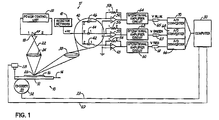
- Fig. 1 is a diagrammatic view of an inspection system in accordance with an embodiment of the invention.
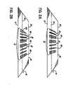
- Figs. 2A and 2B are diagrammatic views of workpieces each including a polychromatic region.
- a process line includes a conveyor 12 moving in an upstream-to-downstream direction, generally indicated by a single-headed arrow 14.
- Conveyor 12 sequentially conveys or transfers a series of workpieces 16, such as cartons or box blanks, in a downstream direction as part of, for example, a packaging operation or a package assembly operation.
- the process line 10 may include, for example, a folder, an adhesive applicator, a printing press, a die cutter, or other conventional devices that process the stream of consecutive workpieces 16.
- An inspection system is positioned in proximity to a portion of the conveyor 12.
- the inspection system 17 is adapted to sense a polychromatic region, which is described hereinafter as being in the form of a polychromatic region 19 (Figs. 2A, 2B), on each of the workpieces 16 transported by the conveyor 12 past inspection system 17.
- the polychromatic region 19 may be a single colored area on the surface of each workpiece 16 and may optionally cover the entire surface or a major portion of the surface of the workpiece 16 that is within the field of view of the inspection system 17.
- the polychromatic region 19 may include a pattern of different colors, or the polychromatic region 19 may include a pattern that represents coded indicia, such as a color bar code, capable of translation but ultimately not translated by the inspection system 17.
- the inspection system 17 includes a light source 18, which has a light output controlled by an adjustable power control unit 20 and is stationary, positioned generally above the conveyor 12.
- the light source 18 emits a beam of light, diagrammatically indicated by reference numeral 22, at a constant distribution of wavelengths that preferably combine to produce white light.
- the incident light from light source 18 is focused by an illumination optical lens 24 to define a focused light spot 26 at a vertical location in the plane of the workpieces 16 arriving on the conveyor 12.
- the beam of light from the light source 18 is typically incident at approximately 90° to a horizontal plane containing the surface of the workpiece 16.
- the light spot 26 illuminates a surface confronting the light source 18 of each successive workpiece 16.
- Particularly useful light sources 18 include the NSPW500BS lamp-type LED commercially available from Nichia Corporation of Japan, which is characterized by chromaticity coordinates of (0.310, 0.320), and the LXHL-LW3C LUXEON® lamp-type LED commercially available from Lumileds Lighting, LLC (San Jose, California), which is characterized by a Lambertian beam pattern and outputs 65 lumens at 700 milliamperes (mA).
- the optical lens 24 may be, for example, a double-concave lens having two inward curved surfaces and negative focal lengths.
- the intensity of the light output by light source 18 may be modulated, and the sensing of the reflected light performed at the modulation frequency of the light output to reject ambient noise.
- Another type of light source usable as light source 18 converts a portion of the light emitted from a blue or ultraviolet LED by making use of phosphor, so as to produce white light.
- the inspection system 17 further includes a stationary position detector 28 suspended generally above the conveyor 12.
- the position detector 28, which may be an optical sensor or photodetector, an inductive sensor, a capacitative sensor, or other type of known sensor, has a field of view that includes the light spot 26 on each workpiece 16 and, preferably, is located downstream from the light spot 26.
- the position detector 28 senses the presence or absence of a reference portion or feature (e.g., leading edge) of each workpiece 16 approaching the light spot 26.
- the position detector 28 generates an output signal representative of the presence of each arriving workpiece 16 and transmits that signal over a communication link or line 29 to a computer 30.
- the light source 18 and position detector 28 may be, for example, positioned downstream from a printing press of the process line 10, upstream from a folder and an adhesive applicator of the process line 10, or downstream from a die cutter of the process line 10.
- a device such as an encoder 32 informs the computer 30 of the line velocity of the conveyor 12 and, hence, the linear speed of each workpiece 16.
- the encoder 32 transmits a string of pulses over a communication link or line 33 to the computer 30 at a frequency representative of the line velocity of the conveyor 12.
- the encoder 32 may be a shaft encoder or any other type of conventional encoder.
- the encoder 32 may be a rotary position transducer coupled with the shaft of a conveyor roller or with the output shaft of a motor powering the conveyor 12.
- a portion of the light reflected from the polychromatic region 19 of the illuminated workpiece 16 is collected by a collection optical component 38 of the inspection system 17 and focused on a color sensor 40 of the inspection system 17.
- the collection optical component 38 may be, for example, a double-convex lens having two outward curved surfaces and positive focal lengths and may include a slit aperture that collimates the reflected light to restrict the collection area.
- the collection optical component 38 collects light reflected specularly at an angle of 45° ⁇ 5° relative to the beam of light from the light source 18.
- housed inside the color sensor 40 is a plurality of, for example, three photodetectors 42, 44 and 46 each of which is adapted to detect incident light within a well-defined frequency or wavelength band of the visible region of the electromagnetic spectrum and generate an analog output signal proportional to the intensity of the detected light
- photodetector 42 may include an optical filter situated in the optical path that transmits light generally in the red wavelength range
- photodetector 44 may include an optical filter in the optical path that transmits light generally in the green wavelength range
- photodetector 46 may include an optical filter in the optical path that transmits light generally in the blue wavelength range.
- the photodetectors 42, 44 and 46 will generate a set of three output signals for each of the different colors in the polychromatic region 19.
- the output signal from each of the photodetectors 42, 44 and 46 will depend upon the light intensity of the reflected light in the corresponding color wavelength band for each of the different colors.
- the wavelength bands sensed by the photodetectors 42, 44 and 46 may collectively span the entire wavelength range of light emitted by the light source 18 or, alternatively, may sample discrete bands of wavelengths in which adjacent sensed wavelength bands are separated by intervening undetected wavelength bands.
- the photodetectors 42, 44 and 46 may be integrated into a single package or platform positionable relative to the arriving workpiece 16.
- a color sensor suitable for use as color sensor 40 is the model MCSAT color sensor package commercially available from Laser Components Instrument Group Inc.
- Si-PIN silicon positive-intrinsic-negative
- MCSiAT color sensor package also commercially available from Laser Components Instrument Group Inc.
- each set of nineteen Si-PIN photodiodes constitutes one of the photodetectors 42, 44 and 46 and the disbursed orientation of the multiple Si-PIN photodiodes over a two (2) mm detection surface provides relatively even color recognition that is substantially independent of target positioning.
- the photodetectors 42, 44 and 46 are voltage biased during operation by a resistor network 41.
- the analog output signal (i.e., current) from each of the photodetectors 42, 44 and 46 is directed to the negative input of one of a plurality of operational amplifiers 48, 50 and 52.
- Resistors 54, 56 and 58 provide a negative feedback path between the output and negative input of a corresponding one of the operational amplifiers 48, 50 and 52.
- the resistance of each of the resistors 54, 56 and 58 determines the gain of a corresponding one of the operational amplifiers 48, 50 and 52.
- Each amplifier 48, 50 and 52 converts the input current from the corresponding one of photodetectors 42, 44 and 46 to an output voltage.
- the output voltage of the operational amplifiers 48, 50 and 52 represent the analog output of the color sensor 40 and will retain the proportionality to the detected light intensity.
- Operational amplifiers suitable for use as operational amplifiers 48, 50 and 52 include the MTI04 Four-Channel Transimpedance Amplifier commercially available from Laser Components Instrument Group Inc. of Hudson, New Hampshire and the OPA267 Operational Amplifier commercially available from The Burr Brown Corporation of Arlington Arizona.
- an output signal 61, 63, 65 from each of the operational amplifiers 48, 50 and 52 (e.g., V Red , V Green , V Blue ), respectively, is amplified and filtered by a corresponding one of a plurality of operational amplifier circuits 60, 62 and 64 for each respective color (i.e., red, green, blue).
- the amplified and filtered output signals 61, 63, 65 are then converted from an analog form to a digital form by one of a plurality of analog-to-digital converters 66, 68 and 70.
- the analog-to-digital converters 66, 68 and 70 may be replaced by analog circuitry.
- Computer 30 includes digital inputs that receive the amplified, filtered, and digitized output signals from the analog-to-digital converters 66, 68 and 70 and evaluates these output signals 61, 63, 65 as a set of ratios. For example, the computer 30 may evaluate the ratio of the red light intensity to blue light intensity, the ratio of the green light intensity to red light intensity, and the ratio of the blue light intensity to green light intensity.
- the color intensity ratios are independent of the intensity of reflected light focused by the collection optical component 38 on color sensor 40. This represents an advantage of the present invention over conventional color detection systems that evaluate absolute color intensities.
- the color intensity ratios may be compared with a reference, such as a target standard ratio, with historical color intensity ratio information from past color intensity ratio measurements, or the color intensity ratio for the polychromatic region 19 on a previous workpiece 16.
- Target standard ratios may be furnished from an exemplary workpiece 16, which teaches a set of color intensity ratios to the computer 30 for comparison with color intensity ratios acquired from subsequent workpieces 16. If the color of the polychromatic region 19 illuminated by the light spot 26 changes, the color intensity ratios will also change,
- Computer 30 may determine whether or not the hue(s) or color shade(s) in the polychromatic region 19 on consecutive workpieces 16 is varying among the individual workpieces 16 by detecting variations in the color intensity ratios. However, computer 30 is not determining an absolute hue or shade of color. In alternative embodiments of the present invention, the computer 30 may determine whether the color intensity ratios for the different colors characterizing the polychromatic region 19 are varying among consecutive workpieces 16 for quality control. This effectively improves the speed of the measurement in comparison with conventional systems that provide an indication of an absolute shade of color or hue. However, the computer 30 is not reading and translating any information that may or may not be encoded in the polychromatic region 19. This effectively improves the speed of the measurement in comparison with conventional systems that decode information encoded in the polychromatic region 19.
- the computer 30 may also use the color intensity ratios to determine whether or not the polychromatic region 19 is accurately positioned in two-dimensions relative to the edges of the workpiece 16. This may be particularly useful in die cutting operations for quality control. If variations are detected, the computer 30 may provide an alert to a parent machine of process line 10, may be used as feedback information to adjust the process, or may be used to reject defective workpieces 16. This takes advantage of the ability to sense contrast in the color intensity ratios between polychromatic region 19 and regions of a different on workpiece 16 near polychromatic region 19, as the light spot 26 moves across the surface of the workpiece 16.
- the computer 30 synchronizes the color intensity ratios with output signals 61, 63, 65 from the position detector 28 and encoder 32.
- the trigger signal from the position detector 28 informs the computer 30 that one of the workpieces 16 is arriving for reading and thereby triggers recording of the reflected light intensities.
- Output signals 61, 63, 65 from the encoder 32 permit the computer 30 to relate the determined color intensity ratios with an absolute location on the workpiece 16.
- the sampling length may be equal to one or more pulses received from the encoder 32. For each workpiece 16, the color intensity ratios measured as a function of location on the workpiece 16 may be stored by the computer 30 for future use.
- Position detector 28 also supplies a trigger signal to computer 30 when another feature (e.g., a trailing edge) of workpiece 16 is detected and the computer 30 responds to the trigger signal by discontinuing the detection or recording of the reflected light intensities.
- another feature e.g., a trailing edge
- the polychromatic region 19 on workpiece 16 may generally include a plurality of colored bars 80 disposed side-by-side in which intervening spaces 81 of a contrasting color separate adjacent bars 80.
- the bar/space pattern defines one or more alphanumeric values in accordance with a predefined standard.
- Each of the bars 80 has an associated color that is assigned when the polychromatic region 19 is printed or otherwise formed on workpiece 16.
- Each bar 80 may have the same color or a different color and, typically, each bar 80 has the same color.
- the light spot 26 (Fig. 1) moves along a longitudinal axis 82 substantially parallel to edges 90, 91 as the workpiece 16 moves in travel direction 14.
- the coloration i.e., the color intensities
- measured by the color sensor 40 varies because of the colors of the bars 80 and the presence of the spaces 81.
- the inspection system 17 determines the uniformity and repeatability of the bars 80 among polychromatic region 19 on successive workpieces 16. Variations may occur during the printing process that the inspection system 17 is capable of detecting and taking corrective measures.
- the inspection system 17 is capable of sensing substantially the entire visible spectrum of colors potentially available for printing or forming bars 80 or at least the portion(s) of the visible spectrum characterizing the colors in the bars 80.
- the inspection system 17 does not read or translate any information encoded in the bars 80 of the polychromatic region 19, which effectively improves the speed of the measurement in comparison with conventional systems that decode this information. This applied to polychromatic regions 19 with information encoded in a string of polychromatic symbols that differ from bars 80.
- polychromatic region 19 may include one or more bars 88 having a geometric shape, a triangle in this case.
- the inspection system 17 can sense a change in the position of the polychromatic region 19 in a direction orthogonal to the direction of motion 14 (i.e., lateral position relative to a feature, such as edges 90 and 91, on workpiece 16) by evaluating the color intensity ratios of the geometrically shaped bar 88.
- the change in the lateral position is sensed by determining the travel distance or displacement of the workpiece 16 in the travel direction 14 across which the color intensity ratio characteristic of bar 88 is sensed by the color sensor 40.
- a variation in this displacement as compared with a standard displacement from either a reference standard, a historical displacement, or the displacement of the previous workpiece 16, indicates that the lateral position of the bar 88 on the particular workpiece 16 is anomalous. If the anomaly continues and is not an isolated event for one or even a few workpieces 16, corrective measures may be required in the process of applying the polychromatic region 19 on successive workpieces 16.
- the color discrimination devices and methods of the various embodiments of the present invention provide high-speed evaluations of colorimetric values, as compared with the capabilities of conventional color detection systems, with relatively inexpensive equipment requiring minimal maintenance.
- the color discrimination devices are capable of vending the spectral uniformity of each of the successive workpieces moving through a production line.
- the increased speed of the measurements arises from the parallel acquisition and processing of the colorimetric values, with 25 microseconds being typical.
- the devices and methods of the invention offer ease of operation and permit the measurement of small targets (e.g., 1 mm).
- a solid-state light source is used in the present invention, in contrast to the conventional halogen light source traditionally used in conventional color detection systems.
- the solid-state light source reduces heat and drift and is long lived, even when mounted on vibrating machinery. Because of the ratiometric conversion of the light intensities determined from the output of the color sensor, field calibration is not required as system components age.
- the present invention also permits accurate determinations of the color ratios in polychromatic regions, such as solid regions, color indicia, or color patterns, on workpieces characterized by specular surfaces that cause variations in the reflected light intensity.
Landscapes
- Physics & Mathematics (AREA)
- Spectroscopy & Molecular Physics (AREA)
- General Physics & Mathematics (AREA)
- General Health & Medical Sciences (AREA)
- Analytical Chemistry (AREA)
- Biochemistry (AREA)
- Chemical & Material Sciences (AREA)
- Life Sciences & Earth Sciences (AREA)
- Immunology (AREA)
- Pathology (AREA)
- Health & Medical Sciences (AREA)
- Spectrometry And Color Measurement (AREA)
- Investigating Materials By The Use Of Optical Means Adapted For Particular Applications (AREA)
Abstract
Description
This may be particularly useful in die cutting operations for quality control. If variations are detected, the computer 30 may provide an alert to a parent machine of process line 10, may be used as feedback information to adjust the process, or may be used to reject defective workpieces 16. This takes advantage of the ability to sense contrast in the color intensity ratios between
Claims (19)
- A device for inspecting a moving workpiece having a polychromatic region, comprising:a solid-state light source adapted to emit light in a range of wavelengths, said light source positioned relative to the moving workpiece to illuminate the polychromatic region with the light; anda plurality of photodetectors each positioned relative to the workpiece to intercept light from said light source reflected by the polychromatic region, each of said photodetectors adapted to detect light within a corresponding one of a plurality of wavelength bands defined within the range of wavelengths.
- The device of claim 1 wherein said light source is a light emitting diode.
- The device of claim 1 wherein the range of wavelengths is within a visible portion of the electromagnetic spectrum, and each of said bands is within the visible portion of the electromagnetic spectrum.
- The device of claim 1 further comprising:a single electronics package integrating said photodetectors.
- A method for inspecting a polychromatic region on a moving workpiece, comprising:illuminating the moving workpiece with light that includes a range of wavelengths;detecting a first intensity of the light reflected from the polychromatic region within a first wavelength band in the range of wavelengths;detecting a second intensity of the light reflected from the polychromatic region within a second wavelength band in the range of wavelengths;determining a ratio of the first intensity to the second intensity; andcomparing the determined ratio with a reference to ascertain a variation in the determined ratio relative to the reference.
- The method of claim 5 wherein the range of wavelengths is within the visible portion of the electromagnetic spectrum.
- The method of claim 5 wherein the first standard ratio is established by averaging the ratio of the first intensity to the second intensity previously evaluated for a plurality of workpieces.
- The method of claim 5 wherein the polychromatic region is a color barcode including a plurality of bars each having a color, and evaluating the ratio further comprises:determining the ratio of the first intensity to the second intensity for at least one of the bars.
- The method of claim 5 wherein the workpiece has an edge and is moving in a travel direction, and the polychromatic region is a color barcode including at least one bar having a dimension that varies in a direction across the workpiece orthogonal to the travel direction and relative to the edge of the workpiece, and evaluating the ratio further comprises:determining a change in the location of the at least one bar on the workpiece relative to the edge.
- The method of claim 9 wherein determining the change in the location further comprises:measuring a displacement of the workpiece in the travel direction across which the ratio is detected; andcomparing the displacement of the workpiece with a reference to ascertain the change in the location of the bar relative to the edge.
- The method of claim 5 further comprising;sensing a first feature of the workpiece; anddetecting the first and second intensities of the reflected light after the feature is sensed.
- The method of claim 11 further comprising:sensing a second feature of the workpiece; anddiscontinuing detection of the first and second intensities of reflected light after the second feature is detected.
- A method for inspecting a plurality of polychromatic regions each carried on a corresponding one of a plurality of moving workpieces, comprising:illuminating each of the moving workpieces with light that includes a range of wavelengths;determining a ratio of the light intensity reflected from the polychromatic region within a first wavelength band in the range of wavelengths to the light intensity reflected from the polychromatic region within a second wavelength band in the range of wavelengths; andcomparing the determined ratio for first and second workpieces among the plurality of workpieces to detect a variation in a color within the polychromatic region between the first and second workpieces.
- The method of claim 13 wherein the polychromatic region has a pattern containing encoded information, and determining the ratio further comprises:determining the ratio without decoding any information in the pattern.
- The method of claim 13 wherein comparing the ratio for different workpieces further comprises:determining the position of the polychromatic region relative to a feature on each of the workpieces.
- The method of claim 15 wherein determining the position further comprises:sensing a feature on each of the workpieces; anddetermining a location of the polychromatic region relative to the sensed feature.
- The method of claim 16 wherein determining the location further comprises:measuring a linear speed at which each of the workpieces is moving when illuminated with the light.
- The method of claim 13 wherein illuminating each of the moving workpieces with light further comprises:illuminating each of The moving workpieces with a light spot that emits light within the range of wavelengths;illuminating each of the moving workpieces with ambient light of a varying intensity and within the range of wavelengths; andrejecting the variations in the intensity of the ambient light when the ratio is determined.
- The method of claim 13 further comprising:detecting the first intensity of the light reflected from the polychromatic region with a first detector sensitive to light within the first wavelength band; anddetecting the second intensity of the light reflected from the polychromatic region with a second detector sensitive to light within the second wavelength band.
Applications Claiming Priority (2)
| Application Number | Priority Date | Filing Date | Title |
|---|---|---|---|
| US56981204P | 2004-05-11 | 2004-05-11 | |
| US569812P | 2004-05-11 |
Publications (2)
| Publication Number | Publication Date |
|---|---|
| EP1596171A2 true EP1596171A2 (en) | 2005-11-16 |
| EP1596171A3 EP1596171A3 (en) | 2010-01-06 |
Family
ID=34936360
Family Applications (1)
| Application Number | Title | Priority Date | Filing Date |
|---|---|---|---|
| EP05010173A Withdrawn EP1596171A3 (en) | 2004-05-11 | 2005-05-11 | Apparatus and methods for high speed RGB color discrimination |
Country Status (3)
| Country | Link |
|---|---|
| US (1) | US7365854B2 (en) |
| EP (1) | EP1596171A3 (en) |
| CN (1) | CN1699978B (en) |
Cited By (1)
| Publication number | Priority date | Publication date | Assignee | Title |
|---|---|---|---|---|
| WO2010097211A1 (en) * | 2009-02-24 | 2010-09-02 | Gatsometer B.V. | Method and device for monitoring the state of a traffic light |
Families Citing this family (11)
| Publication number | Priority date | Publication date | Assignee | Title |
|---|---|---|---|---|
| KR100619054B1 (en) * | 2004-11-09 | 2006-08-31 | 삼성전자주식회사 | Method and apparatus for controlling printing of image using color barcode |
| US8550350B2 (en) * | 2006-02-28 | 2013-10-08 | Konica Minolta Laboratory U.S.A., Inc. | Color barcode with enhanced capacity and readability for a closed loop system |
| FR2926138A1 (en) * | 2008-01-07 | 2009-07-10 | Ecole Nationale D Ingenieurs D | Surface analyzing method for cane for blind, involves emitting predetermined light beams in direction of surface, measuring spectrum, and comparing measured spectrum with predetermined standard spectrum |
| DE102009023948B4 (en) | 2009-06-04 | 2013-05-29 | Baumer Innotec Ag | Device for detecting a mark on a flat object and method therefor, and device for separating sections from a flat object |
| US20100320386A1 (en) * | 2009-06-23 | 2010-12-23 | Nordson Corporation | Adhesive Sensor for Hot Melt and Liquid Adhesives |
| US8526720B2 (en) | 2011-11-17 | 2013-09-03 | Honeywell International, Inc. | Imaging terminal operative for decoding |
| IN2015KO00886A (en) * | 2015-08-14 | 2015-09-11 | Bhattacharyya Dr Siddhartha | |
| CN106934317A (en) * | 2015-12-29 | 2017-07-07 | 我查查信息技术(上海)有限公司 | Bar code scan recognition methods and device |
| JP6891411B2 (en) * | 2016-06-20 | 2021-06-18 | 株式会社リコー | Inspection equipment, inspection methods and programs |
| US10871395B2 (en) * | 2017-04-14 | 2020-12-22 | Kla Corporation | Filter assembly for providing adjustable spectral capabilities in a broadband inspection system |
| CN110286095A (en) * | 2019-07-18 | 2019-09-27 | 黑龙江省烟草公司哈尔滨市公司 | Portable genuine-fake cigarette identifying system, instrument and method based on colour identification test |
Family Cites Families (11)
| Publication number | Priority date | Publication date | Assignee | Title |
|---|---|---|---|---|
| US3910701A (en) * | 1973-07-30 | 1975-10-07 | George R Henderson | Method and apparatus for measuring light reflectance absorption and or transmission |
| JPS52141253A (en) * | 1976-05-19 | 1977-11-25 | Matsushita Electric Ind Co Ltd | Method and apparatus for color separatin |
| DE3242219C1 (en) * | 1982-11-15 | 1984-02-16 | Erwin Sick Gmbh Optik-Elektronik, 7808 Waldkirch | Optical brand recognition device |
| DE3380707D1 (en) * | 1982-11-22 | 1989-11-16 | Hitachi Maxell | Color sensor |
| DE3372140D1 (en) * | 1983-12-14 | 1987-07-23 | Hell Rudolf Dr Ing Gmbh | Method of and device for making colour separations in single colour printing |
| DE3626373A1 (en) | 1986-08-05 | 1988-02-18 | Fritz Kurandt | DEVICE FOR QUICK COLOR MEASUREMENT ON DIFFERENT SAMPLES |
| ATE87737T1 (en) * | 1987-12-03 | 1993-04-15 | Siemens Ag | COLOR SENSOR ARRANGEMENT FOR DETECTING OBJECTS WITH COLORED SURFACES. |
| US5303037A (en) * | 1992-02-24 | 1994-04-12 | Eaton Corporation | Color sensor illumination source employing a lightpipe and multiple LEDs |
| CA2089332A1 (en) * | 1992-03-12 | 1993-09-13 | Robert Bishop | Method of and apparatus for object or surface inspection employing multicolor reflection discrimination |
| JPH11151801A (en) * | 1997-11-22 | 1999-06-08 | Baldwin Japan Ltd | Color optical sensor and printing paper surface inspection apparatus using the same |
| US7046364B2 (en) * | 2003-03-14 | 2006-05-16 | Hewlett-Packard Development Company, L.P. | Method and apparatus for matching gloss levels of printed and unprinted regions of a media substrate |
-
2005
- 2005-05-03 US US10/908,221 patent/US7365854B2/en not_active Expired - Fee Related
- 2005-05-11 EP EP05010173A patent/EP1596171A3/en not_active Withdrawn
- 2005-05-11 CN CN2005100688120A patent/CN1699978B/en not_active Expired - Fee Related
Cited By (1)
| Publication number | Priority date | Publication date | Assignee | Title |
|---|---|---|---|---|
| WO2010097211A1 (en) * | 2009-02-24 | 2010-09-02 | Gatsometer B.V. | Method and device for monitoring the state of a traffic light |
Also Published As
| Publication number | Publication date |
|---|---|
| CN1699978A (en) | 2005-11-23 |
| EP1596171A3 (en) | 2010-01-06 |
| US20050254067A1 (en) | 2005-11-17 |
| US7365854B2 (en) | 2008-04-29 |
| CN1699978B (en) | 2010-09-08 |
Similar Documents
| Publication | Publication Date | Title |
|---|---|---|
| US7259853B2 (en) | Systems and methods for augmenting spectral range of an LED spectrophotometer | |
| US7365854B2 (en) | Apparatus and methods for high speed RGB color discrimination | |
| US6262804B1 (en) | Handheld color measurement instrument | |
| EP2106537B1 (en) | A spectrometer and a method for controlling the spectrometer | |
| EP2596332B1 (en) | Increase of usable dynamic range in photometry | |
| CN105044062B (en) | Aflatoxin on-line measuring device and the material separation device using the device | |
| US20100044441A1 (en) | Color sensing for a reader device and the like | |
| KR20060126431A (en) | Heterogeneous Detector Using Planar Spectrometer | |
| JP2002365139A (en) | Color correction system and spectrophotometer for color printers not sensitive to angle, azimuth and displacement | |
| JP2008157933A (en) | Color measuring head and scanner device equipped with same | |
| JP2000131030A (en) | Apparatus for measuring transversal profile of characteristics of material passage | |
| US20100284009A1 (en) | Color analysis system and method | |
| KR100433980B1 (en) | Method and apparatus for paper material discrimination with two near-infrared lights | |
| KR20070065228A (en) | Paper sheet discrimination apparatus, paper sheet processing apparatus, and paper sheet sheet discrimination method | |
| EP2284512B1 (en) | Improved optical assemblies for low cost spectral imaging with high spectral resolution | |
| US6495831B1 (en) | Method and apparatus for measuring properties of paper | |
| CN101228435A (en) | Detection and Classification of Foreign Substances in Raw Silk Textile Materials | |
| US10605657B2 (en) | Scanner photometer and methods | |
| CA2740114C (en) | Scanner photometer & methods | |
| CN214951807U (en) | Color measurement device based on multicolor LED spectral imaging | |
| EP1716408B1 (en) | Fibre optic measuring apparatus | |
| US10473523B2 (en) | Apparatus for illuminating the surface of a material | |
| US20040164233A1 (en) | Colour sensing apparatus and method | |
| US20130327958A1 (en) | Scanner photometer & methods | |
| KR20240150450A (en) | Compact spectrometer |
Legal Events
| Date | Code | Title | Description |
|---|---|---|---|
| PUAI | Public reference made under article 153(3) epc to a published international application that has entered the european phase |
Free format text: ORIGINAL CODE: 0009012 |
|
| AK | Designated contracting states |
Kind code of ref document: A2 Designated state(s): AT BE BG CH CY CZ DE DK EE ES FI FR GB GR HU IE IS IT LI LT LU MC NL PL PT RO SE SI SK TR |
|
| AX | Request for extension of the european patent |
Extension state: AL BA HR LV MK YU |
|
| PUAL | Search report despatched |
Free format text: ORIGINAL CODE: 0009013 |
|
| AK | Designated contracting states |
Kind code of ref document: A3 Designated state(s): AT BE BG CH CY CZ DE DK EE ES FI FR GB GR HU IE IS IT LI LT LU MC NL PL PT RO SE SI SK TR |
|
| AX | Request for extension of the european patent |
Extension state: AL BA HR LV MK YU |
|
| STAA | Information on the status of an ep patent application or granted ep patent |
Free format text: STATUS: THE APPLICATION IS DEEMED TO BE WITHDRAWN |
|
| 18D | Application deemed to be withdrawn |
Effective date: 20091201 |