EP1596140A2 - Expansion apparatus for refrigerant - Google Patents
Expansion apparatus for refrigerant Download PDFInfo
- Publication number
- EP1596140A2 EP1596140A2 EP05102289A EP05102289A EP1596140A2 EP 1596140 A2 EP1596140 A2 EP 1596140A2 EP 05102289 A EP05102289 A EP 05102289A EP 05102289 A EP05102289 A EP 05102289A EP 1596140 A2 EP1596140 A2 EP 1596140A2
- Authority
- EP
- European Patent Office
- Prior art keywords
- expansion
- refrigerant
- valve
- expansion device
- machine
- Prior art date
- Legal status (The legal status is an assumption and is not a legal conclusion. Google has not performed a legal analysis and makes no representation as to the accuracy of the status listed.)
- Withdrawn
Links
Images


Classifications
-
- F—MECHANICAL ENGINEERING; LIGHTING; HEATING; WEAPONS; BLASTING
- F25—REFRIGERATION OR COOLING; COMBINED HEATING AND REFRIGERATION SYSTEMS; HEAT PUMP SYSTEMS; MANUFACTURE OR STORAGE OF ICE; LIQUEFACTION SOLIDIFICATION OF GASES
- F25B—REFRIGERATION MACHINES, PLANTS OR SYSTEMS; COMBINED HEATING AND REFRIGERATION SYSTEMS; HEAT PUMP SYSTEMS
- F25B9/00—Compression machines, plants or systems, in which the refrigerant is air or other gas of low boiling point
- F25B9/002—Compression machines, plants or systems, in which the refrigerant is air or other gas of low boiling point characterised by the refrigerant
- F25B9/008—Compression machines, plants or systems, in which the refrigerant is air or other gas of low boiling point characterised by the refrigerant the refrigerant being carbon dioxide
-
- F—MECHANICAL ENGINEERING; LIGHTING; HEATING; WEAPONS; BLASTING
- F25—REFRIGERATION OR COOLING; COMBINED HEATING AND REFRIGERATION SYSTEMS; HEAT PUMP SYSTEMS; MANUFACTURE OR STORAGE OF ICE; LIQUEFACTION SOLIDIFICATION OF GASES
- F25B—REFRIGERATION MACHINES, PLANTS OR SYSTEMS; COMBINED HEATING AND REFRIGERATION SYSTEMS; HEAT PUMP SYSTEMS
- F25B41/00—Fluid-circulation arrangements
- F25B41/30—Expansion means; Dispositions thereof
- F25B41/31—Expansion valves
-
- F—MECHANICAL ENGINEERING; LIGHTING; HEATING; WEAPONS; BLASTING
- F25—REFRIGERATION OR COOLING; COMBINED HEATING AND REFRIGERATION SYSTEMS; HEAT PUMP SYSTEMS; MANUFACTURE OR STORAGE OF ICE; LIQUEFACTION SOLIDIFICATION OF GASES
- F25B—REFRIGERATION MACHINES, PLANTS OR SYSTEMS; COMBINED HEATING AND REFRIGERATION SYSTEMS; HEAT PUMP SYSTEMS
- F25B9/00—Compression machines, plants or systems, in which the refrigerant is air or other gas of low boiling point
- F25B9/06—Compression machines, plants or systems, in which the refrigerant is air or other gas of low boiling point using expanders
-
- F—MECHANICAL ENGINEERING; LIGHTING; HEATING; WEAPONS; BLASTING
- F25—REFRIGERATION OR COOLING; COMBINED HEATING AND REFRIGERATION SYSTEMS; HEAT PUMP SYSTEMS; MANUFACTURE OR STORAGE OF ICE; LIQUEFACTION SOLIDIFICATION OF GASES
- F25B—REFRIGERATION MACHINES, PLANTS OR SYSTEMS; COMBINED HEATING AND REFRIGERATION SYSTEMS; HEAT PUMP SYSTEMS
- F25B2309/00—Gas cycle refrigeration machines
- F25B2309/06—Compression machines, plants or systems characterised by the refrigerant being carbon dioxide
- F25B2309/061—Compression machines, plants or systems characterised by the refrigerant being carbon dioxide with cycle highest pressure above the supercritical pressure
-
- F—MECHANICAL ENGINEERING; LIGHTING; HEATING; WEAPONS; BLASTING
- F25—REFRIGERATION OR COOLING; COMBINED HEATING AND REFRIGERATION SYSTEMS; HEAT PUMP SYSTEMS; MANUFACTURE OR STORAGE OF ICE; LIQUEFACTION SOLIDIFICATION OF GASES
- F25B—REFRIGERATION MACHINES, PLANTS OR SYSTEMS; COMBINED HEATING AND REFRIGERATION SYSTEMS; HEAT PUMP SYSTEMS
- F25B2341/00—Details of ejectors not being used as compression device; Details of flow restrictors or expansion valves
- F25B2341/06—Details of flow restrictors or expansion valves
- F25B2341/063—Feed forward expansion valves
-
- F—MECHANICAL ENGINEERING; LIGHTING; HEATING; WEAPONS; BLASTING
- F25—REFRIGERATION OR COOLING; COMBINED HEATING AND REFRIGERATION SYSTEMS; HEAT PUMP SYSTEMS; MANUFACTURE OR STORAGE OF ICE; LIQUEFACTION SOLIDIFICATION OF GASES
- F25B—REFRIGERATION MACHINES, PLANTS OR SYSTEMS; COMBINED HEATING AND REFRIGERATION SYSTEMS; HEAT PUMP SYSTEMS
- F25B2400/00—General features or devices for refrigeration machines, plants or systems, combined heating and refrigeration systems or heat-pump systems, i.e. not limited to a particular subgroup of F25B
- F25B2400/14—Power generation using energy from the expansion of the refrigerant
-
- F—MECHANICAL ENGINEERING; LIGHTING; HEATING; WEAPONS; BLASTING
- F25—REFRIGERATION OR COOLING; COMBINED HEATING AND REFRIGERATION SYSTEMS; HEAT PUMP SYSTEMS; MANUFACTURE OR STORAGE OF ICE; LIQUEFACTION SOLIDIFICATION OF GASES
- F25B—REFRIGERATION MACHINES, PLANTS OR SYSTEMS; COMBINED HEATING AND REFRIGERATION SYSTEMS; HEAT PUMP SYSTEMS
- F25B2500/00—Problems to be solved
- F25B2500/18—Optimization, e.g. high integration of refrigeration components
-
- F—MECHANICAL ENGINEERING; LIGHTING; HEATING; WEAPONS; BLASTING
- F25—REFRIGERATION OR COOLING; COMBINED HEATING AND REFRIGERATION SYSTEMS; HEAT PUMP SYSTEMS; MANUFACTURE OR STORAGE OF ICE; LIQUEFACTION SOLIDIFICATION OF GASES
- F25B—REFRIGERATION MACHINES, PLANTS OR SYSTEMS; COMBINED HEATING AND REFRIGERATION SYSTEMS; HEAT PUMP SYSTEMS
- F25B2600/00—Control issues
- F25B2600/17—Control issues by controlling the pressure of the condenser
-
- F—MECHANICAL ENGINEERING; LIGHTING; HEATING; WEAPONS; BLASTING
- F25—REFRIGERATION OR COOLING; COMBINED HEATING AND REFRIGERATION SYSTEMS; HEAT PUMP SYSTEMS; MANUFACTURE OR STORAGE OF ICE; LIQUEFACTION SOLIDIFICATION OF GASES
- F25B—REFRIGERATION MACHINES, PLANTS OR SYSTEMS; COMBINED HEATING AND REFRIGERATION SYSTEMS; HEAT PUMP SYSTEMS
- F25B40/00—Subcoolers, desuperheaters or superheaters
Definitions
- the present invention relates to an expansion device for a refrigerant, in particular an expansion device for regulating the high pressure level of a Refrigerant circuit of an air conditioner, according to the preamble of claim 1.
- the present invention relates to an air conditioner with such Expansion device.
- the standard version of an air conditioning system generally consists of an evaporator, a condenser or gas cooler, an expansion valve, a compressor and possibly an internal heat exchanger.
- a supercritical operation of the refrigerant and the refrigerant circuit of the air conditioner is required. This means that in the condenser, the refrigerant is not condensed, but that gas is only cooled in the supercritical state. For this reason, the heat exchanger, which operates as a condenser in conventional refrigeration systems and is called in supercritical operation of the refrigeration system and gas cooler.
- the pressure during the heat release can be set independently of the temperature.
- additional degree of freedom typically adjustable expansion valves are used.
- such an expansion valve regulates the high-pressure level of the refrigeration cycle, so that the efficiency of the refrigeration system or the refrigerating capacity of the refrigerant circuit can be optimally adjusted.
- a possibility for improvement of the outlined standard version of a refrigeration system For example, it is the expansion valve through a work-performing Expansion device to replace a so-called expansion machine. To this Way, the expansion process of the refrigeration cycle is designed to be more effective and to be recovered at the same time expansion work. The relaxation energy of the Refrigerant is thus converted into mechanical work and for others, downstream processes made usable.
- DE 198 41 686 A1 discloses a compressor chiller in which a refrigerant is compressed to supercritical pressure in a compressor, then through Heat exchange with the air cooled by a gas cooler and then one Expander is supplied.
- a gear motor having a housing with Has at least two mutually rotatable gears.
- an air conditioner in particular an air conditioner for motor vehicles is known, whose refrigerant circuit has a gear machine with a helical toothing, which serves as an expansion machine for the supercritical refrigerant.
- the gear machine generates energy during the expansion process of the refrigerant, inter alia by recovering the volume change work, which in turn can be used in the refrigerant circuit for compressing the refrigerant.
- the air conditioning system of DE 100 13 191 C1 is configured in such a way that the refrigerant carbon dioxide (CO 2 ) in the refrigerant circuit is brought from a supercritical state into a wet steam state.
- the expansion device according to the invention for a refrigerant in particular a Such expansion device for controlling the high pressure level of Refrigerant circuit of an air conditioner, has at least one expansion valve and a Expansion machine on.
- the expansion device becomes part of the heavy control tasks of the expansion process, or the Safety tasks of the expansion machine from the machine to the expansion valve transfer.
- the expansion machine thus has only the task of Energy recovery, and the recovered energy in the appropriate form to to provide further use.
- the setting of the high pressure and the Safety function is provided by the expansion valve expansion valve accepted.
- Both the expansion machine and the variable expansion valve are in series with each other Refrigerant circuit of the air conditioning arranged.
- Expansion means are the variable expansion valve and the expansion machine arranged parallel to each other in the refrigerant circuit of the air conditioner.
- the Parallel connection of expansion valve and expansion machine also makes it possible to simplify the dimensioning of the expansion machine. This can be done in the case of Parallel connection designed only for the usual or optimal mass flow with the expansion valve being used, if increased Mass flows would occur.
- the expansion valve is a controllable valve, with which can regulate the high pressure level of the refrigerant circuit. It can be both externally and internally controlled.
- the Expansion valve can be an electrically operated valve or even a mechanical or thermally controlled valve.
- a possible embodiment of the expansion valve which can be used, consists in an overflow valve, which at a predetermined mass flow of the coolant opens.
- Expansion device are their controllable expansion valve and the Expansion machine in a structural unit to a compact module summarized.
- a module can be easily in corresponding Integrate refrigeration circuits.
- the expansion machine Since the control of the high pressure level of the refrigerant circuit substantially by the expansion valve is made, the expansion machine has only the Task to provide the recovered energy in an appropriate form. So can the Drive shaft of the expansion machine, for example, directly to the drive shaft of the Refrigerant compressor be coupled or coupled. This is especially one advantageous development of the claimed expansion device, since the Speed of the expander expansion machine independent of the Control of the high pressure can be selected. An adaptation of the speed of the Expansion machine to the speed of the compressor can thus be done freely.
- the generated Volume flow can be set arbitrarily, since it is no longer dependent on the regulation of High pressure levels of the refrigerant is affected.
- the task of a regulation of Expansion machine for adjusting the high pressure level in the refrigerant circuit and the provision of the recoverable mechanical energy in an appropriate form advantageously no longer linked together. Because these two tasks are included Expansion machines of the prior art have different requirements for the Speed of the expansion machine have been complex solutions, such as a controllable transmission to achieve an additional Degrees of freedom.
- An advantageous development of the expansion device according to the invention results in the event that the expander of the expander with a electrical machine, in particular with an electric generator operatively connected or is operatively connected.
- the expansion valve of the Expansion device can set the optimum high pressure while the characteristic the expansion machine, for example, the characteristic of a conventional motor vehicle generator equivalent.
- the regulation of the output voltage of the generator is by such Arrangement greatly simplified.
- the freely selectable speed of the expansion machine of the claimed expansion device thus allows a constant Output voltage at the generator.
- required Security functions are optimized.
- a particularly advantageous embodiment of the device according to the invention results in that the expansion device or at least the expansion machine the expansion device in a structural unit with an electric machine, For example, a generator is designed. So it is possible to use both machine, d. H. Both the expansion machine, as well as the electric machine in one common housing, which typically forms a hermetic unit, to arrange.
- inventive expansion device can be in Advantageously, an air conditioner, in particular a dynamically operated Further develop air conditioning for a motor vehicle.
- an air conditioner in particular a dynamically operated Further develop air conditioning for a motor vehicle.
- the inventive expansion device thus makes it possible to control a To simplify the expansion machine or to make such a regulation possible.
- FIG. 1 in principle refrigerant circuit 10 of an air conditioner has a compressor 12, a condenser or gas cooler 14, an expansion device 16 and an evaporator 18, which via corresponding connecting means 20th are interconnected and form a closed refrigerant circuit.
- the components of this circuit are operated in the manner of a compression refrigeration cycle.
- a compression of a refrigerant such as the refrigerant CO 2 by a compressor, the so-called air compressor or simply compressor, carried out to increase the internal energy of the refrigerant.
- the compressed refrigerant is then cooled in a condenser or condenser by heat exchange.
- this heat exchanger 14 is referred to as gas cooler when using the supercritical operation of the refrigerant.
- the thus cooled refrigerant is expanded by means of an expansion device 16 to a lower pressure and further cooled.
- the expansion device 16 is usually followed by an evaporator 18, which is operated as a heat exchanger to transfer the released refrigerant of the refrigerant to another medium.
- This other medium, which interacts with the cold, expanded refrigerant via the evaporator may be, for example, air which is supplied to a vehicle heating or cooling system (air conditioning system).
- thermodynamic Circular process By controlling the throttling at the expansion device of Refrigerant circulation can be the pressure on the high pressure side of the thermodynamic Circular process can be controlled or regulated, so that the specific cooling capacity of the Air conditioning can be varied in the desired manner. So it is possible one to obtain maximum effective coefficient of performance by the pressure of the high pressure side of the Thermodynamic cycle (high pressure level) depending on the Temperature at the gas cooler outlet or the ambient temperature in an adapted manner is set.
- thermodynamic Properties that release heat in the supercritical range can be the high pressure level be set at the heat emission regardless of the temperature.
- additional To use degree of freedom in an advantageous manner can be controlled and / or regulated Expansion facilities are used.
- Fig. 2 shows a first embodiment of a special refrigerant circuit for a Air conditioning system using an expansion device 16 according to the invention.
- the refrigerant circuit 10 of a CO 2 air conditioning system has a compressor 12, which may be electrically operated, for example, or else driven by corresponding coupling elements of the internal combustion engine of a motor vehicle.
- a compressor 12 first of all, compression of the refrigerant, in the case described CO 2 , is carried out in order to increase the internal energy of the refrigerant.
- a separator in particular an oil separator 20 is provided, which serves to deposit the oil residues contained in the gaseous refrigerant and provide these via appropriate connecting means 22, for example, in turn, the compressor 12 for lubrication.
- the compressed and possibly purified refrigerant is cooled in a downstream condenser or gas cooler 14 by a heat exchange and is doing a portion of its internal heat energy to the air conditioning, such as a vehicle, so that the temperature of the refrigerant drops and this possibly liquefied.
- the air conditioning such as a vehicle
- the refrigerant in the gas cooler 14 is not condensed but merely cooled, so that in this case one does not speak of a condenser but of a gas cooler.
- an inner heat exchanger 24 is provided, which makes it possible compressed, cooled refrigerants by means of the returning and already expanded and cooled refrigerant continue to cool down.
- the compressed refrigerant is now supplied to an expansion device 16 and in this expanded to a lower pressure level.
- the inventive Expansion device 16 consists at least of a regulated expansion valve 26 and an expansion machine 36.
- the expansion valve 26 is a adjustable valve, which by a corresponding position of the throttle body of the Valve can release a desired opening area and thus the Pressure level on the high pressure side of the refrigerant circuit 10 determined.
- the Expansion valve 26 may, for example, an electromagnetically actuated valve or but also be a purely mechanically controlled, or a thermally controlled valve. This can be both an external, as well as an internally controlled valve act. be.
- the controllable expansion valve 26 is followed by a Expansion machine 36, which in principle by every work Expansion device may be formed.
- expansion machines are particularly conceivable and advantageous, so-called Gear machines, which effectively convert the expansion energy into mechanical Enable work.
- the expansion machine can then be operatively connected to other downstream components of the motor vehicle or in a request case operatively connected.
- the expansion process in the expansion device 16 more effective and at the same time regain expansion work.
- the relaxation energy of the refrigerant is converted into mechanical work and thus made available for other processes.
- the expansion machine 36 and the compressor 12 in a structural Unit be summarized.
- the expansion device 16 consisting of at least the variable expansion valve 26 and the downstream expansion machine 36th as a compact module in a structural unit.
- This carrier medium may be, for example, air, which is a vehicle Heating or cooling system (air conditioning), which is not shown in Fig. 2, in be supplied in a known manner.
- a so-called collector 28 which serves as a liquid separator or storage.
- a Collector 28 is particularly necessary if the filling of the evaporator 18th can not be regulated.
- the collector 28 separates on the one hand after the Evaporator still in the refrigerant existing liquid components and collects this example, in its lower part.
- the collector also has the task of Store refrigerant in order to compensate for small leaks in the system can. With the help of the collector can also small unevenness of the mass flow of the refrigerant can be compensated. These occur, for example, in a Speed increase of the compressor. This increases the mass flow of Refrigerant, without first the evaporator 18 can evaporate more refrigerant.
- Fig. 3 shows an alternative embodiment of the expansion device according to the invention 16 of a refrigerant circuit 10.
- the expansion device 16 according to the Embodiment of Fig. 3 has at least one controllable expansion valve 26 as well an expansion machine 36.
- the Expansion valve 26 and the expansion machine 36 parallel to each other in Refrigerant circuit 10 is arranged.
- This arrangement can be in an advantageous manner Way through a compact module 30 realize.
- the parallel connection of Expansion machine 36 and the expansion valve 26 allows the Dimensioning of the expansion machine 36 simplify. This can be in this case then be designed only for a common mass flow. Should, however, increased Mass flows occur, so they can be derived with the help of the expansion valve become. In this way is a compact and simple expansion machine usable.
- the parallel circuit according to the embodiment in Fig. 3 also means a not insignificant advantage for the safety of the refrigeration system.
- the Expansion machine 36 may place the expansion valve 26 in an "emergency stop mode". be regulated, which allows a safe shutdown of the refrigeration system.
- FIG. 3 shows the previously described refrigeration cycle according to FIG. 2.
- the two presented refrigeration cycles and especially the two Expander 16 of these refrigeration circuits is meant that part of the Control tasks of the expansion device 16 of the expansion machine 36 the expansion valve 26 is transmitted.
- the expansion machine 36 thus only has the task of providing the recoverable energy in the desired form.
- the regulation of the high pressure level in the refrigeration cycle 10 and thus the determination of Cooling capacity or the efficiency of the air conditioner is in an advantageous manner taken over the expansion valve 26.
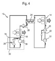
- FIG. 4 shows another embodiment of a refrigerant circuit 10 for a inventive air conditioning.
- the refrigeration cycle 10 corresponds according to the embodiment of Fig. 4 the previously described refrigeration cycle after 3, so that at this point only to the corresponding description of Figure 3 is referenced.
- the expansion device 16 of the refrigeration cycle in the embodiment according to Figure 4 as an expansion valve overflow valve 27, which at a predetermined Mass flow of the refrigerant, or at a corresponding pressure of the refrigerant opens to a throttle body of the valve.
- the throttle body of the overflow valve 27th This is due to the pressure of the refrigerant applied to the inlet side of the valve placed against the force, for example a spring-elastic element. this makes possible the adjustment of the pressure level on the high pressure side of the refrigerant circuit easy way. Elaborate and therefore cost-intensive electronically controlled Expansion organs can be avoided in this case.
- the overflow valve 27 may be formed, for example, as a sliding seat valve.
- a sliding seat valve By modifying the gap geometry of a conventional sliding seat valve leaves the tightness of such a valve significantly improve.
- the gap geometry between the valve piston (Slide element) and piston guide (seat of the slide) of the sliding seat valve be optimized.
- Such a modification allows the use of the Sliding seat valve as an expansion element in an air conditioning system, allowing a good Controllability with a total of low-noise operation in all operating conditions allows becomes.
- the overflow valve 27 is not on the design of a sliding seat valve limited.
- inventive refrigerant circuit of an air conditioner or the Expansion device for a refrigerant according to the invention are not on the in the Drawing illustrated embodiments limited.
- the air conditioning system according to the invention is not based on the use of a limited internal heat exchanger in the refrigerant circuit.
- the erfmdungshiele expansion device and the corresponding air conditioning is not limited to the use of CO 2 as a refrigerant.
Abstract
Description
Die vorliegende Erfindung betrifft eine Expansionseinrichtung für ein Kältemittel, insbesondere eine Expansionseinrichtung zur Regelung des Hochdruckniveaus eines Kältemittelkreislaufs einer Klimaanlage, nach dem Oberbegriff des Anspruchs 1. Des weiteren betrifft die vorliegende Erfindung eine Klimaanlage mit einer derartigen Expansionseinrichtung.The present invention relates to an expansion device for a refrigerant, in particular an expansion device for regulating the high pressure level of a Refrigerant circuit of an air conditioner, according to the preamble of claim 1. Des Furthermore, the present invention relates to an air conditioner with such Expansion device.
Die Standardausführung einer Klimaanlage besteht im allgemeinen aus einem Verdampfer, einem Kondensator bzw. Gaskühler, einem Expansionsventil, einem Verdichter und ggf. aus einem inneren Wärmeübertrager. Wird insbesondere das Kältemittel CO2 verwendet, ist zumindest unter einigen Umgebungsbedingungen eine überkritische Betriebsweise des Kältemittels und des Kältemittelkreislaufs der Klimaanlage erforderlich. Dies bedeutet, dass im Kondensator das Kältemittel nicht kondensiert wird, sondern dass Gas im überkritischen Zustand lediglich abgekühlt wird. Aus diesem Grunde wird der Wärmeübertrager, der in konventionellen Kälteanlagen als Kondensator arbeitet und bezeichnet wird, bei überkritischer Betriebsweise der Kälteanlage auch Gaskühler genannt.The standard version of an air conditioning system generally consists of an evaporator, a condenser or gas cooler, an expansion valve, a compressor and possibly an internal heat exchanger. In particular, when the refrigerant CO 2 is used, at least under some environmental conditions, a supercritical operation of the refrigerant and the refrigerant circuit of the air conditioner is required. This means that in the condenser, the refrigerant is not condensed, but that gas is only cooled in the supercritical state. For this reason, the heat exchanger, which operates as a condenser in conventional refrigeration systems and is called in supercritical operation of the refrigeration system and gas cooler.
In Kälteanlagen mit Kältemitteln, die aufgrund ihrer thermodynamischer Eigenschaften die Wärme im überkritischen Bereich abgeben, kann der Druck bei der Wärmeabgabe unabhängig von der Temperatur eingestellt werden. Um diesen, gegenüber Kältemitteln mit Wärmeabgabe im Nassdampfgebiet, zusätzlichen Freiheitsgrad nutzen zu können, werden typischer Weise regelbare Expansionsventile eingesetzt. So erfolgt bei dem Kältemittel CO2 durch ein solches Expansionsventil eine Regelung des Hochdruckniveaus des Kältekreislaufs, so dass der Wirkungsgrad der Kälteanlage oder die Kälteleistung des Kältemittelkreislaufs optimal eingestellt werden können.In refrigeration systems with refrigerants which, due to their thermodynamic properties, release the heat in the supercritical range, the pressure during the heat release can be set independently of the temperature. In order to use this, compared to refrigerants with heat in the wet steam area, additional degree of freedom, typically adjustable expansion valves are used. Thus, in the case of the refrigerant CO 2, such an expansion valve regulates the high-pressure level of the refrigeration cycle, so that the efficiency of the refrigeration system or the refrigerating capacity of the refrigerant circuit can be optimally adjusted.
Eine Verbesserungsmöglichkeit der skizzierten Standardausführung einer Kälteanlage besteht beispielsweise darin, das Expansionsventil durch eine arbeitsleistende Expansionseinrichtung, eine sogenannten Expansionsmaschine zu ersetzen. Auf diese Weise soll der Expansionsvorgang des Kältekreislaufs effektiver gestaltet und gleichzeitig Expansionsarbeit zurückgewonnen werden. Die Entspannungsenergie des Kältemittels wird somit in mechanische Arbeit umgewandelt und für andere, nachgeschaltete Prozesse nutzbar gemacht.A possibility for improvement of the outlined standard version of a refrigeration system For example, it is the expansion valve through a work-performing Expansion device to replace a so-called expansion machine. To this Way, the expansion process of the refrigeration cycle is designed to be more effective and to be recovered at the same time expansion work. The relaxation energy of the Refrigerant is thus converted into mechanical work and for others, downstream processes made usable.
Aus dem Stand der Technik sind verschiedene technische Lösungen bekannt, um eine Expansionsmaschine praktisch zu realisieren.From the prior art, various technical solutions are known to a To realize expansion machine practically.
Die DE 198 41 686 A1 offenbart eine Verdichterkältemaschine bei dem ein Kältemittel auf überkritischen Druck in einem Verdichter komprimiert wird, anschließend durch Wärmeaustausch mit der Luft mittels eines Gaskühlers gekühlt und dann einer Expansionsmaschine zugeführt wird. Als Expansions- bzw. Entspannungsmaschine für das gekühlte Kältemittel, welches sich auf kritischem Druckniveau befindet, wird in der Vorrichtung der DE 198 41 686 A1 ein Zahnradmotor verwendet, der ein Gehäuse mit mindestens zwei gegeneinander rotierbaren Zahnrädern aufweist.DE 198 41 686 A1 discloses a compressor chiller in which a refrigerant is compressed to supercritical pressure in a compressor, then through Heat exchange with the air cooled by a gas cooler and then one Expander is supplied. As an expansion or relaxation machine for The cooled refrigerant, which is at critical pressure level, is in the Device of DE 198 41 686 A1 uses a gear motor having a housing with Has at least two mutually rotatable gears.
Aus der DE 100 13 191 C1 ist eine Klimaanlage, insbesondere eine Klimaanlage für Kraftfahrzeuge bekannt, deren Kältemittelkreislauf eine Zahnradmaschine mit einer Schrägverzahnung aufweist, die als Expansionsmaschine für das überkritische Kältemittel dient. Durch die Zahnradmaschine wird beim Expansionsvorgang des Kältemittels Energie, u. a. durch Zurückgewinnung der Volumenänderungsarbeit, erzeugt, die wiederum im Kältemittelkreislauf zur Verdichtung des Kältemittels verwendet werden kann. Die Klimaanlage der DE 100 13 191 C1 ist derart ausgestaltet, dass das Kältemittel Kohlendioxid (CO2) im Kältemittelkreislauf aus einem überkritischen Zustand in einen Nassdampfzustand gebracht wird.From DE 100 13 191 C1 an air conditioner, in particular an air conditioner for motor vehicles is known, whose refrigerant circuit has a gear machine with a helical toothing, which serves as an expansion machine for the supercritical refrigerant. The gear machine generates energy during the expansion process of the refrigerant, inter alia by recovering the volume change work, which in turn can be used in the refrigerant circuit for compressing the refrigerant. The air conditioning system of DE 100 13 191 C1 is configured in such a way that the refrigerant carbon dioxide (CO 2 ) in the refrigerant circuit is brought from a supercritical state into a wet steam state.
Unabhängig von der jeweils ausgewählten Technologie stellen die Regelungsanforderungen der Expansionsmaschine eine besondere Herausforderung dar. Regardless of the selected technology, the Regulatory requirements of the expansion machine is a particular challenge dar.
Ein weiteres Problem besteht darin, dass eine Expansionsmaschine eine Sicherheitsfunktion zu erfüllen hat. Die Expansionsmaschine soll bei zu extremen Belastungen des Systems, ermöglichen, das System in einen stabilen Zustand zurück zu bringen oder gegebenenfalls das System sicher abzuschalten. Diese extremen Bedingungen, die weit von den normalen Betriebszuständen entfernt sind, müssen daher bei der Auslegung der Expansionsmaschine berücksichtigt werden, was eine optimale Auslegung der Expansionsmaschine, insbesondere im Normalbetrieb schwer macht.Another problem is that an expansion machine a Safety function has to fulfill. The expansion machine is supposed to be too extreme Loads of the system, allow the system to return to a stable state or, if necessary, shut down the system safely. These extremes Conditions that are far removed from the normal operating conditions must therefore be considered in the design of the expansion machine, which is an optimal Design of the expansion machine, especially in normal operation makes heavy.
Die erfindungsgemäße Expansionseinrichtung für ein Kältemittel, insbesondere eine solche Expansionseinrichtung zur Regelung des Hochdruckniveaus eines Kältemittelkreislaufs einer Klimaanlage, weist zumindest ein Expansionsventil und eine Expansionsmaschine auf. Durch diesen kombinierten Aufbau der Expansionseinrichtung wird ein Teil der schweren Regelungsaufgaben des Expansionsvorgangs, bzw. auch der Sicherheitsaufgaben der Expansionsmaschine von der Maschine auf das Expansionsventil übertragen. Die Expansionsmaschine hat somit nur noch die Aufgabe der Energierückgewinnung, und die zurückgewonnene Energie in der passenden Form zur weiteren Nutzung bereit zu stellen. Die Einstellung des Hochdrucks sowie die Sicherheitsfunktion wird durch das Expansionsventil der Expansionseinrichtung übernommen.The expansion device according to the invention for a refrigerant, in particular a Such expansion device for controlling the high pressure level of Refrigerant circuit of an air conditioner, has at least one expansion valve and a Expansion machine on. By this combined structure of the expansion device becomes part of the heavy control tasks of the expansion process, or the Safety tasks of the expansion machine from the machine to the expansion valve transfer. The expansion machine thus has only the task of Energy recovery, and the recovered energy in the appropriate form to to provide further use. The setting of the high pressure and the Safety function is provided by the expansion valve expansion valve accepted.
Auf diese Weise ist es möglich, eine Expansionseinrichtung für ein Kältemittel derart zu betreiben, dass sowohl die Einstellung des Hochdruckniveaus als auch die Bereitstellung der zurückgewonnenen Energie in voneinander nahezu unabhängiger und damit optimaler Weise durchführbar ist. So kann beispielsweise die Drehzahl der Expansionsmaschine auf die Energienutzung und Umwandlung optimiert werden, ohne dass das einzustellende Hochdruckniveau hierbei zu beachten ist.In this way, it is possible to an expansion device for a refrigerant such operate both the setting of the high pressure level and the provision the energy recovered in each other from almost independent and thus optimal Way is feasible. For example, the speed of the expansion machine on the energy use and conversion are optimized without the need to be adjusted High pressure level is to be observed here.
Durch die in den Unteransprüchen aufgeführten Merkmale sind vorteilhafte Weiterbildungen der erfindungsgemäßen Expansionseinrichtung möglich. The features listed in the dependent claims are advantageous Further developments of the expansion device according to the invention possible.
In einer vorteilhaften Ausführungsform der erfindungsgemäßen Expansionseinrichtung sind die Expansionsmaschine und das regelbare Expansionsventil in Reihe zueinander im Kältemittelkreislauf der Klimaanlage angeordnet.In an advantageous embodiment of the expansion device according to the invention Both the expansion machine and the variable expansion valve are in series with each other Refrigerant circuit of the air conditioning arranged.
In einer alternativen, vorteilhaften Ausführungsform der erfindungsgemäßen Expansionseinrichtung sind das regelbare Expansionsventil und die Expansionsmaschine parallel zueinander im Kältemittelkreislauf der Klimaanlage angeordnet. Die Parallelschaltung von Expansionsventil und Expansionsmaschine ermöglicht es zudem die Dimensionierung der Expansionsmaschine zu vereinfachen. Diese kann im Fall der Parallelschaltung nur noch für den üblichen bzw. optimalen Massenstrom ausgelegt werden, wobei das Expansionsventil zum Einsatz kommen würde, falls erhöhte Massenströme auftreten würden.In an alternative, advantageous embodiment of the invention Expansion means are the variable expansion valve and the expansion machine arranged parallel to each other in the refrigerant circuit of the air conditioner. The Parallel connection of expansion valve and expansion machine also makes it possible to simplify the dimensioning of the expansion machine. This can be done in the case of Parallel connection designed only for the usual or optimal mass flow with the expansion valve being used, if increased Mass flows would occur.
Eine solche Parallelschaltung der wesentlichen Komponenten der Expansionseinrichtung bedeutet auch hinsichtlich der Sicherheit der Kälteanlage einen nicht zu vernachlässigenden Vorteil. So kann beim Ausfall der Expansionsmaschine das Expansionsventil in einen "Not-Aus-Modus" eintreten und trotz funktionsunfähiger Expansionsmaschine ein sicheres Ausschalten der Anlage gewährleisten.Such a parallel connection of the essential components of the expansion device also means one with regard to the safety of the refrigeration system negligible benefit. So can the failure of the expansion machine the Expansion valve in an "emergency stop mode" occur and despite inoperative Expansion machine ensure a safe shutdown of the plant.
In vorteilhaften Ausführungsformen ist das Expansionsventil ein regelbares Ventil, mit dem sich das Hochdruckniveau des Kältemittelkreislauf regeln lässt. Dabei kann es sich sowohl um ein extern, als auch um ein intern geregeltes Ventil handeln. Das Expansionsventil kann ein elektrisch betriebenes Ventil oder auch ein mechanisch oder thermisch geregeltes Ventil sein. Eine mögliche Ausführungsform des Expansionsventils welche eingesetzt werden kann, besteht in einem Überströmventil, welches bei einem vorgegebenen Massenstrom des Kühlmittels öffnet.In advantageous embodiments, the expansion valve is a controllable valve, with which can regulate the high pressure level of the refrigerant circuit. It can be both externally and internally controlled. The Expansion valve can be an electrically operated valve or even a mechanical or thermally controlled valve. A possible embodiment of the expansion valve which can be used, consists in an overflow valve, which at a predetermined mass flow of the coolant opens.
In einer besonders vorteilhaften Ausführungsform der erfindungsgemäßen Expansionsvorrichtung, sind deren regelbares Expansionsventil sowie die Expansionsmaschine in einer baulichen Einheit zu einem kompakten Modul zusammengefasst. Ein solches Modul lässt sich in einfacher Weise in entsprechende Kältekreisläufe integrieren.In a particularly advantageous embodiment of the invention Expansion device, are their controllable expansion valve and the Expansion machine in a structural unit to a compact module summarized. Such a module can be easily in corresponding Integrate refrigeration circuits.
Da die Regelung des Hochdruckniveaus des Kältemittelkreislaufs im wesentlichen durch das Expansionsventil vorgenommen wird, hat die Expansionsmaschine nur noch die Aufgabe, die zurückgewonnene Energie in passender Form bereitzustellen. So kann die Antriebswelle der Expansionsmaschine beispielsweise direkt mit der Antriebswelle des Kältemittelverdichters verkoppelt bzw. verkoppelbar sein. Dies ist insbesondere eine vorteilhafte Weiterentwicklung der beanspruchten Expansionsvorrichtung, da die Drehzahl der Expansionsmaschine der Expansionsverrichtung unabhängig von der Regelung des Hochdrucks gewählt werden kann. Eine Anpassung der Drehzahl der Expansionsmaschine an die Drehzahl des Verdichters kann somit frei erfolgen.Since the control of the high pressure level of the refrigerant circuit substantially by the expansion valve is made, the expansion machine has only the Task to provide the recovered energy in an appropriate form. So can the Drive shaft of the expansion machine, for example, directly to the drive shaft of the Refrigerant compressor be coupled or coupled. This is especially one advantageous development of the claimed expansion device, since the Speed of the expander expansion machine independent of the Control of the high pressure can be selected. An adaptation of the speed of the Expansion machine to the speed of the compressor can thus be done freely.
Falls die Expansionsmaschine in vorteilhafter Weise eine Vor- oder Nachverdichtungseinrichtung für das Kältemittel antreibt, kann der erzeugte Volumenstrom beliebig eingestellt werden, da er nicht mehr von der Regelung des Hochdruckniveaus des Kältemittels beeinflusst wird. Die Aufgabe einer Regelung der Expansionsmaschine zur Einstellung des Hochdruckniveaus im Kältemittelkreislauf und die Bereitstellung der zurückgewinnbaren mechanischen Energie in passender Form sind in vorteilhafter Weise nicht mehr miteinander verknüpft. Da diese beiden Aufgaben bei Expansionsmaschinen des Standes der Technik unterschiedliche Anforderungen an die Drehzahl der Expansionsmaschine gestellt haben, waren bisher aufwendige Lösungen, wie beispielsweise ein ansteuerbares Getriebe zur Erzielung eines zusätzlichen Freiheitsgrades von Nöten.If the expansion machine advantageously a forward or Compressor for the refrigerant drives, the generated Volume flow can be set arbitrarily, since it is no longer dependent on the regulation of High pressure levels of the refrigerant is affected. The task of a regulation of Expansion machine for adjusting the high pressure level in the refrigerant circuit and the provision of the recoverable mechanical energy in an appropriate form advantageously no longer linked together. Because these two tasks are included Expansion machines of the prior art have different requirements for the Speed of the expansion machine have been complex solutions, such as a controllable transmission to achieve an additional Degrees of freedom.
Eine vorteilhafte Weiterbildung der erfindungsgemäßen Expansionseinrichtung ergibt sich für den Fall, dass die Expansionsmaschine der Expansionseinrichtung mit einer elektrischen Maschine, insbesondere mit einem elektrischen Generator wirkverbunden oder wirkverbindbar ist. Wenn die zurückgewonnene Energie mittels eines Generators in elektrische Energie umgewandelt werden soll, so ist die beanspruchte Expansionseinrichtung von großem Nutzen. Das Expansionsventil der Expansionseinrichtung kann den optimalen Hochdruck einstellen, während die Kennlinie der Expansionsmaschine beispielsweise der Kennlinie eines üblichen KFZ-Generators entspricht. Die Regelung der Ausgangsspannung des Generators wird durch eine solche Anordnung stark vereinfacht. Die frei wählbare Drehzahl der Expansionsmaschine der beanspruchten Expansionsvorrichtung ermöglicht somit eine konstante Ausgangsspannung am Generator. Darüber hinaus können erforderliche Sicherheitsfunktionen optimiert werden. An advantageous development of the expansion device according to the invention results in the event that the expander of the expander with a electrical machine, in particular with an electric generator operatively connected or is operatively connected. When the recovered energy by means of a generator in electrical energy is to be converted, so is the claimed Expansion device of great benefit. The expansion valve of the Expansion device can set the optimum high pressure while the characteristic the expansion machine, for example, the characteristic of a conventional motor vehicle generator equivalent. The regulation of the output voltage of the generator is by such Arrangement greatly simplified. The freely selectable speed of the expansion machine of the claimed expansion device thus allows a constant Output voltage at the generator. In addition, required Security functions are optimized.
Eine besonders vorteilhafte Ausführungsform der erfindungsgemäßen Vorrichtung ergibt sich dadurch, dass die Expansionseinrichtung bzw. zumindest die Expansionsmaschine der Expansionseinrichtung in einer baulichen Einheit mit einer elektrischen Maschine, beispielsweise einem Generator ausgestaltet ist. So ist es möglich, beide Maschine, d. h. sowohl die Expansionsmaschine, als auch die elektrische Maschine in einem gemeinsamen Gehäuse, welches typischer Weise eine hermetische Einheit bildet, anzuordnen.A particularly advantageous embodiment of the device according to the invention results in that the expansion device or at least the expansion machine the expansion device in a structural unit with an electric machine, For example, a generator is designed. So it is possible to use both machine, d. H. Both the expansion machine, as well as the electric machine in one common housing, which typically forms a hermetic unit, to arrange.
Mit der beanspruchten, erfmdungsgemäßen Expansionsvorrichtung lässt sich in vorteilhafter Weise eine Klimaanlage, insbesondere eine dynamisch betriebene Klimaanlage für ein Kraftfahrzeug weiterbilden. Durch die Aufgabenteilung der Komponenten der Expansionseinrichtung des Kältekreislaufs der Klimaanlage lässt sich sowohl die Regelung des Hochdruckniveaus des Kältemittels und somit der Wirkungsgrad bzw. die Kälteleistung des Kältekreislaufs optimieren als auch zusätzlich Energie durch den Expansionsprozess mittels einer Expansionsmaschine gewinnen. Die somit gewonnene zusätzliche Energie lässt sich in vorteilhafter Weise zum Betrieb weiterer Komponenten der Klimaanlage bzw. des Kältekreislaufs einsetzen.With the claimed, inventive expansion device can be in Advantageously, an air conditioner, in particular a dynamically operated Further develop air conditioning for a motor vehicle. By the division of tasks of the Components of the expansion device of the refrigeration cycle of the air conditioning can be both the regulation of the high pressure level of the refrigerant and thus the Optimize efficiency and the cooling capacity of the refrigeration cycle as well as in addition Gain energy through the expansion process by means of an expansion machine. The thus obtained additional energy can be advantageously for operation use other components of the air conditioning or refrigeration circuit.
Insbesondere für ein Kältemittel, welches die Wärme im überkritischen Bereich abgibt, wie dies beispielsweise beim Kältemittel CO2 der Fall ist, ergibt sich somit eine vorteilhafte Weiterbildung des Kältekreislaufs und einer mit einem solchen Kältekreislauf verbundenen Klimaanlage.In particular, for a refrigerant which releases the heat in the supercritical region, as is the case with the refrigerant CO 2, for example, thus results in an advantageous development of the refrigeration cycle and a connected to such a refrigeration cycle air conditioning.
Die erfmdungsgemäße Expansionseinrichtung ermöglicht es somit die Regelung einer Expansionsmaschine zu vereinfachen bzw. eine solche Regelung erst möglich zu machen.The inventive expansion device thus makes it possible to control a To simplify the expansion machine or to make such a regulation possible.
Weitere Vorteile und Merkmale der erfindungsgemäßen Expansionseinrichtung bzw. einer erfindungsgemäßen Klimaanlage mit einer solchen Expansionseinrichtung im Kältemittelkreislauf ergeben sich aus der nachfolgenden Beschreibung einiger Ausführungsbeispiele.Further advantages and features of the expansion device according to the invention or an air conditioning system according to the invention with such an expansion device in Refrigerant circuit will become apparent from the following description of some Embodiments.
In der Zeichnung sind drei Ausführungsbeispiele der erfindungsgemäßen Expansionseinrichtung bzw. Beispiele dreier Kältemittelkreisläufe unter Verwendung von erfindungsgemäßen Expansionseinrichtungen dargestellt, die in der nachfolgenden Beschreibung näher erläutert werden sollen. Die Figuren der Zeichnungen, deren Beschreibung sowie die Ansprüche enthalten zahlreiche Merkmale in Kombination. Ein Fachmann wird diese Merkmale auch einzeln betrachten und zu weiteren, sinnvollen Kombinationen zusammenfassen, die somit als ebenfalls offenbart anzusehen sind.In the drawing, three embodiments of the invention Expander or examples of three refrigerant circuits using Expansion devices according to the invention shown in the following Description will be explained in more detail. The figures of the drawings, whose Description and claims contain numerous features in combination. One A person skilled in the art will also consider these features individually and make further, meaningful ones Combine combinations, which are thus to be regarded as also disclosed.
- Fig. 1Fig. 1
- eine schematische Darstellung des Kältemittelkreislaufs einer Klimaanlage,a schematic representation of the refrigerant circuit of an air conditioner,
- Fig. 2Fig. 2
- ein erstes Ausführungsbeispiel für eine in einem Kältemittelkreislauf angeordnete Expansionsvorrichtung,a first embodiment of a in a refrigerant circuit arranged expansion device,
- Fig. 3Fig. 3
- ein zweites Ausführungsbeispiel für eine erfindungsgemäße Expansionseinrichtung sowie den zugehörigen Kältemittelkreislauf einer Klimaanlage,a second embodiment of an inventive Expansion device and the associated refrigerant circuit a Air conditioning,
- Fig. 4.Fig. 4.
- ein weiteres Ausführungsbeispiel für eine erfindungsgemäße Expansionseinrichtung sowie den zugehörigen Kältemittelkreislauf einer Klimaanlage.a further embodiment of an inventive Expansion device and the associated refrigerant circuit a Air conditioning.
Der in Fig. 1 im Prinzip dargestellte Kältemittelkreislauf 10 einer Klimaanlage weist
einen Kompressor 12, einen Kondensator oder Gaskühler 14, eine Expansionseinrichtung
16 und einen Verdampfer 18 auf, die über entsprechende Verbindungsmittel 20
miteinander verbunden sind und einen geschlossenen Kältemittelkreislauf bilden.The illustrated in Fig. 1 in principle
Die Komponenten dieses Kreislaufs werden nach Art eines Kompressionskältekreislaufs
betrieben. Hierbei wird zunächst eine Verdichtung eines Kältemittels, beispielsweise des
Kältemittels CO2 durch einen Verdichter, den sogenannten Klimakompressor oder
einfach Kompressor, durchgeführt, um die innere Energie des Kältemittels zu erhöhen.
Das komprimierte Kältemittel wird anschließend in einem Kondensator oder Verflüssiger
durch einen Wärmeaustausch gekühlt. Bei Kältemitteln, die die Wärme im überkritischen
Bereich abgeben, wie dies beispielsweise bei dem Kältemittel CO2 der Fall ist, wird das
Kältemittel im Kondensator nicht verflüssigt, sondern als Gas im überkritischen Zustand
nur abgekühlt. Aus diesem Grunde wird dieser Wärmeübertrager 14 bei Verwendung der
überkritischen Betriebsweise des Kältemittels als Gaskühler bezeichnet. Anschließend
wird das so gekühlte Kältemittel mittels einer Expansionseinrichtung 16 auf einen
geringeren Druck ausgedehnt und dabei weiter abgekühlt. Der Expansionseinrichtung 16
ist in der Regel ein Verdampfer 18 nachgeschaltet, der als Wärmetauscher betrieben wird,
um die freiwerdende Kälte des Kältemittels auf ein anderes Medium zu übertragen.
Dieses andere Medium, welches über den Verdampfer mit dem kalten, expandierten
Kältemittel in Wechselwirkung tritt, kann beispielsweise Luft sein, die einem Fahrzeug
Heizungs- bzw. Kühlsystem (Klimaanlage) zugeführt wird.The components of this circuit are operated in the manner of a compression refrigeration cycle. Here, first, a compression of a refrigerant, such as the refrigerant CO 2 by a compressor, the so-called air compressor or simply compressor, carried out to increase the internal energy of the refrigerant. The compressed refrigerant is then cooled in a condenser or condenser by heat exchange. In the case of refrigerants which release the heat in the supercritical range, as is the case, for example, with the refrigerant CO 2 , the refrigerant in the condenser is not liquefied but only cooled as gas in the supercritical state. For this reason, this
Durch die Steuerung der Drosselung an der Expansionseinrichtung des Kältemittelkreislaufs kann der Druck auf der Hochdruckseite des thermodynamischen Kreisprozesses gesteuert bzw. geregelt werden, so dass die spezifische Kälteleistung der Klimaanlage in gewünschter Weise variiert werden kann. So ist es möglich, eine maximale effektive Leistungszahl zu erhalten, indem der Druck der Hochdruckseite des thermodynamischen Kreisprozesses (Hochdruckniveau) in Abhängigkeit von der Temperatur am Gaskühlerausgang oder der Umgebungstemperatur in angepasster Weise eingestellt wird.By controlling the throttling at the expansion device of Refrigerant circulation can be the pressure on the high pressure side of the thermodynamic Circular process can be controlled or regulated, so that the specific cooling capacity of the Air conditioning can be varied in the desired manner. So it is possible one to obtain maximum effective coefficient of performance by the pressure of the high pressure side of the Thermodynamic cycle (high pressure level) depending on the Temperature at the gas cooler outlet or the ambient temperature in an adapted manner is set.
Insbesondere bei Kälteanlagen mit Kältemitteln, die aufgrund ihrer thermodynamischen Eigenschaften die Wärme im überkritischen Bereich abgeben, kann das Hochdruckniveau bei der Wärmeabgabe unabhängig von der Temperatur eingestellt werden. Um diesen, gegenüber Kältemitteln mit Wärmeabgabe im Nassdampfbereich zusätzlichen Freiheitsgrad in vorteilhafter Weise zu nutzen, können steuer- und/oder regelbare Expansionseinrichtungen genutzt werden.Especially in refrigeration systems with refrigerants, due to their thermodynamic Properties that release heat in the supercritical range can be the high pressure level be set at the heat emission regardless of the temperature. To this, compared to refrigerants with heat emission in the wet steam area additional To use degree of freedom in an advantageous manner, can be controlled and / or regulated Expansion facilities are used.
Fig. 2 zeigt ein erstes Ausführungsbeispiel eines speziellen Kältemittelkreislaufs für eine
Klimaanlage unter Verwendung einer erfmdungsgemäßen Expansionseinrichtung 16.Fig. 2 shows a first embodiment of a special refrigerant circuit for a
Air conditioning system using an
Der Kältemittelkreislauf 10 einer CO2-Klimaanlage gemäß Figur 2 weist einen
Kompressor 12 auf, der beispielsweise elektrisch betrieben oder aber auch über
entsprechende Kupplungselemente von der Brennkraftmaschine eines Kraftfahrzeuges
angetrieben sein kann. Im Kompressor 12 wird zunächst eine Verdichtung des
Kältemittels, im beschriebenen Fall CO2, durchgeführt, um die innere Energie des
Kältemittels zu erhöhen. In Strömungsrichtung nach dem Verdichter 12 ist ein
Abscheider, insbesondere ein Ölabscheider 20 vorgesehen, der dazu dient, die im
gasförmigen Kältemittel enthaltenen Ölrückstände abzuscheiden und diese über
entsprechende Verbindungsmittel 22 beispielsweise wiederum dem Kompressor 12 zur
Schmierung zur Verfügung zu stellen.The
Das komprimierte und gegebenenfalls gereinigte Kältemittel wird in einem
nachgeschalteten Kondensator bzw. Gaskühler 14 durch einen Wärmeaustausch gekühlt
und gibt dabei einen Teil seiner inneren Wärmeenergie an die Klimaanlage,
beispielsweise eines Fahrzeuges ab, so dass die Temperatur des Kältemittels absinkt und
sich dieses ggf. verflüssigt. Wird als Kältemittel ein transkritisches Kältemittel, wie
beispielsweise CO2 genutzt, so wird das Kältemittel im Gaskühler 14 nicht kondensiert
sondern lediglich abgekühlt, so dass man in diesem Fall nicht von einem Kondensator
sondern von einem Gaskühler spricht.The compressed and possibly purified refrigerant is cooled in a downstream condenser or gas cooler 14 by a heat exchange and is doing a portion of its internal heat energy to the air conditioning, such as a vehicle, so that the temperature of the refrigerant drops and this possibly liquefied. If a transcritical refrigerant, such as CO 2, is used as the refrigerant, then the refrigerant in the
Zur weiteren Absenkung der Temperatur des Kältemittels ist im Kältemittelkreislauf 10
gemäß Fig. 2 ein innerer Wärmetauscher 24 vorgesehen, der es ermöglicht das
komprimierte, gekühlte Kältemittel mittels des rücklaufenden und bereits expandierten
und abgekühlten Kältemittels weiter herunterzukühlen.To further reduce the temperature of the refrigerant is in the refrigerant circuit 10th
2, an
Das komprimierte Kältemittel wird nunmehr einer Expansionseinrichtung 16 zugeführt
und in dieser auf ein geringeres Druckniveau expandiert. Die erfindungsgemäße
Expansionseinrichtung 16 besteht zumindest aus einem geregelten Expansionsventil 26
und einer Expansionsmaschine 36. Im Ausführungsbeispiel gemäß Fig. 2 sind das
Expansionsventil 26 und die Expansionsmaschine 36 in Reihe zueinander im
Kühlkreislauf 10 des Kältemittels geschaltet. Das Expansionsventil 26 ist dabei ein
regelbares Ventil, welches durch eine entsprechende Stellung des Drosselkörpers des
Ventils einen gewünschten Öffnungsquerschnitt freigeben kann und somit das
Druckniveau auf der Hochdruckseite des Kältemittelkreislaufs 10 bestimmt. Das
Expansionsventil 26 kann beispielsweise ein elektromagnetisch angesteuertes Ventil oder
aber auch ein rein mechanisch geregeltes, oder auch ein thermisch geregeltes Ventil sein.
Dabei kann es sich sowohl um ein extern, als auch um ein intern geregeltes Ventil
handeln. sein. Dem regelbaren Expansionsventil 26 nachgeschaltet ist eine
Expansionsmaschine 36, welche prinzipiell durch jede arbeitsleistende
Expansionseinrichtung gebildet sein kann.The compressed refrigerant is now supplied to an
Als Expansionsmaschinen sind insbesondere denkbar und vorteilhaft, sogenannte Zahnradmaschinen, die eine effektive Umsetzung der Expansionsenergie in mechanische Arbeit ermöglichen. Über eine entsprechende Welle kann die Expansionsmaschine dann mit weiteren nachgeschalteten Komponenten des Kraftfahrzeugs wirkverbunden sein bzw. in einem Anforderungsfall wirkverbunden werden.As expansion machines are particularly conceivable and advantageous, so-called Gear machines, which effectively convert the expansion energy into mechanical Enable work. About a corresponding wave, the expansion machine can then be operatively connected to other downstream components of the motor vehicle or in a request case operatively connected.
Auf diese Weise ist es möglich, den Expansionsvorgang in der Expansionseinrichtung 16
effektiver zu gestalten und gleichzeitig Expansionsarbeit zurückzugewinnen. Hierbei
wird die Entspannungsenergie des Kältemittels in mechanische Arbeit umgewandelt und
somit für andere Prozesse verfügbar gemacht. So kann beispielsweise durch eine
Kopplung der Antriebswelle der Expansionsmaschine 36 mit der Antriebswelle des
Verdichters 12, die mit der Expansionsmaschine gewonnene Arbeit direkt wieder im
Kältemittelkreislauf genutzt werden. In speziellen Ausführungsbeispielen können hierzu
beispielsweise die Expansionsmaschine 36 und der Verdichter 12 in einer baulichen
Einheit zusammengefasst werden.In this way it is possible, the expansion process in the
Ebenso vorteilhaft kann es sein, die Expansionseinrichtung 16, bestehend zumindest aus
dem regelbaren Expansionsventil 26 und der nachgeschalteten Expansionsmaschine 36
als ein kompaktes Modul in einer baulichen Einheit auszubilden.It may also be advantageous, the
Der Expansionseinrichtung 16 nachgeschaltet ist ein Verdampfer 18, der als
Wärmetauscher betrieben wird, um die freiwerdende Kälte auf ein Trägermedium zu
übertragen. Dieses Trägermedium kann beispielsweise Luft sein, die einem Fahrzeug
Heiz- bzw. Kühlsystem (Klimaanlage), welches in Fig. 2 nicht weiter dargestellt ist, in
bekannter Weise zugeführt werden.Downstream of the
Dem Verdampfer 18 nachgeschaltet ist im Ausführungsbeispiel der Figur 2 ein
sogenannter Sammler 28, der als Flüssigkeitsabscheider bzw. Speicher dient. Ein solcher
Sammler 28 ist insbesondere dann von Nöten, wenn die Befüllung des Verdampfers 18
nicht geregelt werden kann. Der Sammler 28 scheidet zum einen die nach dem
Verdampfer noch im Kältemittel vorhandenen flüssigen Bestandteile ab und sammelt
diese beispielsweise in seinem unteren Bereich. Der Sammler hat zudem die Aufgabe,
Kältemittel zu bevorraten, um kleine Leckagen des Systems kompensieren zu können.
Mit Hilfe des Sammlers können zudem kleine Ungleichmäßigkeiten des Massenstroms
des Kältemittels ausgeglichen werden. Diese treten beispielsweise bei einer
Drehzahlanhebung des Kompressors auf. Dabei erhöht sich der Massenstrom des
Kältemittels, ohne dass zunächst der Verdampfer 18 mehr Kältemittel verdampfen kann.
Das nach dem Verdampfer noch flüssige, d. h. nicht verdampfte Kältemittel wird im
Sammler 28 abgeschieden und gespeichert. Bei einer Drehzahlverringerung des
Kompressors muss dann das flüssige Kältemittel aus dem Sammler wieder in den
Verdampfer 28 befördert werden. Dies erfolgt dadurch, dass das flüssige Kältemittel
mittels des Kompressors aus dem Sammler angesaugt und in den Kältemittelkreislauf 10
befördert wird.Downstream of the
Fig. 3 zeigt eine alternative Ausgestaltung der erfindungsgemäßen Expansionseinrichtung
16 eines Kältemittelkreislaufs 10. Die Expansionseinrichtung 16 gemäß dem
Ausführungsbeispiel der Fig. 3 weist zumindest ein regelbares Expansionsventil 26 sowie
eine Expansionsmaschine 36 auf. In der Ausführungsform gemäß Fig. 3 sind das
Expansionsventil 26 und die Expansionsmaschine 36 parallel zueinander im
Kältemittelkreislauf 10 angeordnet. Auch diese Anordnung lässt sich in vorteilhafter
Weise durch ein kompaktes Modul 30 realisieren. Die Parallelschaltung der
Expansionsmaschine 36 und des Expansionsventils 26 ermöglicht es, die
Dimensionierung der Expansionsmaschine 36 zu vereinfachen. Diese kann in diesem Fall
dann lediglich für einen üblichen Massenstrom ausgelegt werden. Sollten jedoch erhöhte
Massenströme auftreten, so können diese mit Hilfe des Expansionsventils abgeleitet
werden. Auf diese Weise ist eine kompakte und einfache Expansionsmaschine
verwendbar.Fig. 3 shows an alternative embodiment of the expansion device according to the
Die Parallelschaltung gemäß dem Ausführungsbeispiel in Fig. 3 bedeutet zudem einen
nicht unerheblichen Vorteil für die Sicherheit der Kälteanlage. Bei einem Ausfall der
Expansionsmaschine 36 kann das Expansionsventil 26 in einen "Not-Aus-Modus"
geregelt werden, der ein sicheres Abschalten der Kälteanlage ermöglicht.The parallel circuit according to the embodiment in Fig. 3 also means a
not insignificant advantage for the safety of the refrigeration system. In case of failure of the
In seinem sonstigen Aufbau entspricht der Kältekreislauf 10 gemäß Ausführungsbeispiel
der Fig. 3 dem zuvor beschriebenen Kältekreislauf nach Fig. 2. In its other construction corresponds to the
Den beiden vorgestellten Kältekreisläufen und insbesondere den beiden
Expansionseinrichtungen 16 dieser Kältekreisläufe ist gemeint, dass ein Teil der
Regelungsaufgaben der Expansionseinrichtung 16 von der Expansionsmaschine 36 auf
das Expansionsventil 26 übertragen wird. Die Expansionsmaschine 36 hat somit nur noch
die Aufgabe, die zurückgewinnbare Energie in der gewünschten Form bereitzustellen.
Die Regelung des Hochdruckniveaus im Kältekreislauf 10 und somit die Bestimmung der
Kälteleistung oder der Wirkungsgrad der Klimaanlage wird in vorteilhafter Weise durch
das Expansionsventil 26 übernommen.The two presented refrigeration cycles and especially the two
Figur 4 zeigt ein weiteres Ausführungsbeispiel eines Kältemittelkreislaufs 10 für eine
erfindungsgemäße Klimaanlage. In seinem Aufbau entspricht der Kältekreislauf 10
gemäß dem Ausführungsbeispiel der Fig. 4 dem zuvor beschriebenen Kältekreislauf nach
Fig. 3, so dass an dieser Stelle lediglich auf die entsprechende Beschreibung zu Figur 3
verwiesen wird. Im Unterschied zu dem in Figur 3 dargestellten Ausführungsbeispiel
besitzt die Expansionseinrichtung 16 des Kältekreislaufs in der Ausführungsform gemäß
Figur 4 als Expansionsventil ein Überströmventil 27, welches bei einem vorgebbaren
Massenstrom des Kältemittels, bzw. bei einem entsprechenden Druck des Kältemittels
auf einen Drosselkörper des Ventils öffnet. Der Drosselkörper des Überströmventils 27
wird dabei durch den auf der Einlassseite des Ventils anliegenden Druck des Kältemittels
gegen die Kraft, beispielsweise eines federelastischen Elementes gestellt. Dies ermöglicht
die Einstellung des Druckniveaus auf der Hochdruckseite des Kältemittelkreislaufes auf
einfache Weise. Aufwendige und dadurch auch kostenintensive elektronisch gesteuerte
Expansionsorgane können in diesem Falle vermieden werden.Figure 4 shows another embodiment of a
Dabei kann das Überströmventil 27 beispielsweise als Schiebesitzventil ausgebildet sein. Durch die Modifikation der Spaltgeometrie eines herkömmlichen Schiebesitzventils lässt sich die Dichtheit eines solchen Ventils deutlich verbessern. Insbesondere kann durch eine Verlängerung des Ventilkolbens die Spaltgeometrie zwischen Ventilkolben (Schieberelement) und Kolbenführung (Sitz des Schiebers) des Schiebesitzventils optimiert werden. Eine solche Modifikation ermöglicht die Verwendung des Schiebesitzventils als Expansionsorgan in einer Klimaanlage, so dass eine gute Regelbarkeit bei insgesamt geräuscharmem Betrieb in allen Betriebszuständen ermöglicht wird. Das Überströmventil 27 ist jedoch nicht auf die Bauform eines Schiebesitzventils beschränkt. In this case, the overflow valve 27 may be formed, for example, as a sliding seat valve. By modifying the gap geometry of a conventional sliding seat valve leaves the tightness of such a valve significantly improve. In particular, by an extension of the valve piston, the gap geometry between the valve piston (Slide element) and piston guide (seat of the slide) of the sliding seat valve be optimized. Such a modification allows the use of the Sliding seat valve as an expansion element in an air conditioning system, allowing a good Controllability with a total of low-noise operation in all operating conditions allows becomes. However, the overflow valve 27 is not on the design of a sliding seat valve limited.
Der erfindungsgemäße Kältemittelkreislauf einer Klimaanlage bzw. die erfindungsgemäße Expansionseinrichtung für ein Kältemittel sind nicht auf die in der Zeichnung dargestellten Ausführungsbeispiele beschränkt.The inventive refrigerant circuit of an air conditioner or the Expansion device for a refrigerant according to the invention are not on the in the Drawing illustrated embodiments limited.
Insbesondere ist die erfindungsgemäße Klimaanlage nicht auf die Verwendung eines inneren Wärmeübertragers im Kältemittelkreislauf beschränkt.In particular, the air conditioning system according to the invention is not based on the use of a limited internal heat exchanger in the refrigerant circuit.
Des weiteren ist die erfmdungsgemäße Expansionsvorrichtung sowie die entsprechende auf Klimaanlage nicht die Verwendung von CO2 als Kältemittel beschränkt.Furthermore, the erfmdungsgemäße expansion device and the corresponding air conditioning is not limited to the use of CO 2 as a refrigerant.
Claims (15)
Applications Claiming Priority (2)
| Application Number | Priority Date | Filing Date | Title |
|---|---|---|---|
| DE102004023834A DE102004023834A1 (en) | 2004-05-14 | 2004-05-14 | Expansion device for a refrigerant |
| DE102004023834 | 2004-05-14 |
Publications (2)
| Publication Number | Publication Date |
|---|---|
| EP1596140A2 true EP1596140A2 (en) | 2005-11-16 |
| EP1596140A3 EP1596140A3 (en) | 2010-04-28 |
Family
ID=34939039
Family Applications (1)
| Application Number | Title | Priority Date | Filing Date |
|---|---|---|---|
| EP05102289A Withdrawn EP1596140A3 (en) | 2004-05-14 | 2005-03-22 | Expansion apparatus for refrigerant |
Country Status (3)
| Country | Link |
|---|---|
| EP (1) | EP1596140A3 (en) |
| JP (1) | JP2005326145A (en) |
| DE (1) | DE102004023834A1 (en) |
Cited By (3)
| Publication number | Priority date | Publication date | Assignee | Title |
|---|---|---|---|---|
| CN103604239A (en) * | 2013-11-15 | 2014-02-26 | 杭州锦华气体设备有限公司 | Large-cold-storage gas expansion refrigerating system and refrigerating method thereof |
| CN104246393A (en) * | 2012-04-23 | 2014-12-24 | 三菱电机株式会社 | Refrigeration cycle system |
| US20190049156A1 (en) * | 2013-03-14 | 2019-02-14 | Rolls-Royce Corporation | Thermal management system controlling dynamic and steady state thermal loads |
Families Citing this family (5)
| Publication number | Priority date | Publication date | Assignee | Title |
|---|---|---|---|---|
| DE102005058890B4 (en) * | 2005-12-09 | 2007-08-30 | Festo Ag & Co. | Air conditioning of a motor vehicle |
| FR2895786B1 (en) * | 2006-01-04 | 2008-04-11 | Valeo Systemes Thermiques | RELAXATION MODULE FOR AIR CONDITIONING INSTALLATION WITH TWO EVAPORATORS |
| DE102006033747B3 (en) * | 2006-07-21 | 2008-01-10 | Thomas Magnete Gmbh | valve assembly |
| DE102008041939A1 (en) * | 2008-09-10 | 2010-03-11 | Ago Ag Energie + Anlagen | A method of operating a heat pump or chiller or engine and heat pump or chiller and engine |
| DE102012014967A1 (en) * | 2012-07-30 | 2014-01-30 | Isabelle Oelschlägel | Integrated device for power generation used during operation of compression heat pump of heating system in e.g. washing machine, has water-wheel-claimant generator that is formed in region of expansion valve |
Citations (9)
| Publication number | Priority date | Publication date | Assignee | Title |
|---|---|---|---|---|
| EP0787891A2 (en) * | 1996-01-31 | 1997-08-06 | Carrier Corporation | Deriving mechanical power by expanding a liquid to its vapour |
| JP2000234814A (en) * | 1999-02-17 | 2000-08-29 | Aisin Seiki Co Ltd | Vapor compressed refrigerating device |
| DE10010864A1 (en) * | 1999-03-15 | 2000-09-21 | Denso Corp | Refrigeration circuit system has expansion energy recovery unit that converts expansion energy into mechanical energy and compresses coolant flowing into cooler |
| EP1046869A1 (en) * | 1999-04-20 | 2000-10-25 | Sanden Corporation | Refrigeration/air conditioning system |
| JP2002022298A (en) * | 2000-07-04 | 2002-01-23 | Matsushita Electric Ind Co Ltd | Refrigeration cycle device and method for controlling the same |
| JP2003074999A (en) * | 2001-08-31 | 2003-03-12 | Daikin Ind Ltd | Refrigerating machine |
| JP2003121018A (en) * | 2001-10-09 | 2003-04-23 | Daikin Ind Ltd | Refrigerating apparatus |
| JP2003279179A (en) * | 2002-03-26 | 2003-10-02 | Mitsubishi Electric Corp | Refrigerating air conditioning device |
| EP1416232A1 (en) * | 2002-10-31 | 2004-05-06 | Matsushita Electric Industrial Co., Ltd. | High pressure determining method in a refrigeration cycle system |
-
2004
- 2004-05-14 DE DE102004023834A patent/DE102004023834A1/en not_active Withdrawn
-
2005
- 2005-03-22 EP EP05102289A patent/EP1596140A3/en not_active Withdrawn
- 2005-05-12 JP JP2005140199A patent/JP2005326145A/en not_active Withdrawn
Patent Citations (9)
| Publication number | Priority date | Publication date | Assignee | Title |
|---|---|---|---|---|
| EP0787891A2 (en) * | 1996-01-31 | 1997-08-06 | Carrier Corporation | Deriving mechanical power by expanding a liquid to its vapour |
| JP2000234814A (en) * | 1999-02-17 | 2000-08-29 | Aisin Seiki Co Ltd | Vapor compressed refrigerating device |
| DE10010864A1 (en) * | 1999-03-15 | 2000-09-21 | Denso Corp | Refrigeration circuit system has expansion energy recovery unit that converts expansion energy into mechanical energy and compresses coolant flowing into cooler |
| EP1046869A1 (en) * | 1999-04-20 | 2000-10-25 | Sanden Corporation | Refrigeration/air conditioning system |
| JP2002022298A (en) * | 2000-07-04 | 2002-01-23 | Matsushita Electric Ind Co Ltd | Refrigeration cycle device and method for controlling the same |
| JP2003074999A (en) * | 2001-08-31 | 2003-03-12 | Daikin Ind Ltd | Refrigerating machine |
| JP2003121018A (en) * | 2001-10-09 | 2003-04-23 | Daikin Ind Ltd | Refrigerating apparatus |
| JP2003279179A (en) * | 2002-03-26 | 2003-10-02 | Mitsubishi Electric Corp | Refrigerating air conditioning device |
| EP1416232A1 (en) * | 2002-10-31 | 2004-05-06 | Matsushita Electric Industrial Co., Ltd. | High pressure determining method in a refrigeration cycle system |
Non-Patent Citations (1)
| Title |
|---|
| ROBINSON D M ET AL: "Efficiencies of transcritical CO2 cycles with and without an expansion turbine - Rendement de cycles transcritiques au CO2 avec et sans turbine d'expansion" INTERNATIONAL JOURNAL OF REFRIGERATION, ELSEVIER, PARIS, FR, Bd. 21, Nr. 7, 1. November 1998 (1998-11-01), Seiten 577-589, XP004287371 ISSN: 0140-7007 * |
Cited By (5)
| Publication number | Priority date | Publication date | Assignee | Title |
|---|---|---|---|---|
| CN104246393A (en) * | 2012-04-23 | 2014-12-24 | 三菱电机株式会社 | Refrigeration cycle system |
| CN104246393B (en) * | 2012-04-23 | 2016-06-22 | 三菱电机株式会社 | Freezing cyclic system |
| US20190049156A1 (en) * | 2013-03-14 | 2019-02-14 | Rolls-Royce Corporation | Thermal management system controlling dynamic and steady state thermal loads |
| US11448432B2 (en) * | 2013-03-14 | 2022-09-20 | Rolls-Royce Corporation | Adaptive trans-critical CO2 cooling system |
| CN103604239A (en) * | 2013-11-15 | 2014-02-26 | 杭州锦华气体设备有限公司 | Large-cold-storage gas expansion refrigerating system and refrigerating method thereof |
Also Published As
| Publication number | Publication date |
|---|---|
| JP2005326145A (en) | 2005-11-24 |
| DE102004023834A1 (en) | 2005-12-08 |
| EP1596140A3 (en) | 2010-04-28 |
Similar Documents
| Publication | Publication Date | Title |
|---|---|---|
| EP1596140A2 (en) | Expansion apparatus for refrigerant | |
| DE102005049831B4 (en) | Vapor compression cooling device | |
| EP1262347A2 (en) | Heating/cooling circuit for an air conditioning of a motor vehicle, air conditioning and its control method | |
| DE102005032277A1 (en) | Vapor compression refrigeration unit | |
| EP1152911B1 (en) | Motor vehicle air-conditioning system and a method for operating a motor vehicle air conditioning system | |
| DE102017100591B3 (en) | Refrigerant circuit, in particular for motor vehicles with electric or hybrid drive and method for operating the refrigerant circuit | |
| EP1499511A1 (en) | Air conditioner | |
| DE102004055695A1 (en) | Waste heat collection system with a Rankine cycle and a heating circuit | |
| DE102012111455A1 (en) | Refrigerant circuit of a vehicle air conditioning system and method for air conditioning a vehicle interior | |
| DE102012208992B4 (en) | Heating/cooling circuit for vehicles, especially for hybrid vehicles or purely electric vehicles | |
| DE102018114762B4 (en) | Method for operating an air conditioning system in a motor vehicle | |
| EP1578628B1 (en) | Air conditioning system for a vehicle and associated operating method | |
| DE102018207049A1 (en) | Refrigeration system for a vehicle having a heat pump function having a refrigerant circuit | |
| DE102005032458A1 (en) | Refrigeration system, in particular motor vehicle air conditioning | |
| DE102005005430A1 (en) | Method for operating of air conditioning system in motor vehicle in which in heating mode compressed cooling medium is directed through 3/2 directional valve through gas cooler to transfer heat to air flowing into interior of vehicle | |
| DE10013191C1 (en) | Air conditioning system, in particular for motor vehicles and method for operating an air conditioning system, in particular for motor vehicles | |
| DE102018112333A1 (en) | Refrigerant circuit with an expansion-compression device and method for operating the refrigerant circuit | |
| DE102017213973A1 (en) | Method for operating a refrigeration system of a vehicle having a refrigerant circuit having a cooling and heating function | |
| WO2004055454A1 (en) | Coolant circuit for a motor vehicle air conditioning system | |
| EP0582282A1 (en) | Cold air refrigerating installation | |
| DE102021003045A1 (en) | Cooling device for cooling charge air for an internal combustion engine | |
| DE102020108393A1 (en) | Temperature control device for a vehicle | |
| DE102019008767A1 (en) | Temperature control device for cooling charge air for an internal combustion engine | |
| DE10240711B4 (en) | Expansion organ of a motor vehicle air conditioner | |
| DE10338388B3 (en) | Method for controlling an air conditioning system |
Legal Events
| Date | Code | Title | Description |
|---|---|---|---|
| PUAI | Public reference made under article 153(3) epc to a published international application that has entered the european phase |
Free format text: ORIGINAL CODE: 0009012 |
|
| AK | Designated contracting states |
Kind code of ref document: A2 Designated state(s): AT BE BG CH CY CZ DE DK EE ES FI FR GB GR HU IE IS IT LI LT LU MC NL PL PT RO SE SI SK TR |
|
| AX | Request for extension of the european patent |
Extension state: AL BA HR LV MK YU |
|
| PUAL | Search report despatched |
Free format text: ORIGINAL CODE: 0009013 |
|
| AK | Designated contracting states |
Kind code of ref document: A3 Designated state(s): AT BE BG CH CY CZ DE DK EE ES FI FR GB GR HU IE IS IT LI LT LU MC NL PL PT RO SE SI SK TR |
|
| AX | Request for extension of the european patent |
Extension state: AL BA HR LV MK YU |
|
| AKY | No designation fees paid | ||
| STAA | Information on the status of an ep patent application or granted ep patent |
Free format text: STATUS: THE APPLICATION IS DEEMED TO BE WITHDRAWN |
|
| 18D | Application deemed to be withdrawn |
Effective date: 20101001 |
|
| REG | Reference to a national code |
Ref country code: DE Ref legal event code: R108 Effective date: 20110329 Ref country code: DE Ref legal event code: 8566 |