EP1596129A1 - Behandlungsverfahren für gasgenerator - Google Patents
Behandlungsverfahren für gasgenerator Download PDFInfo
- Publication number
- EP1596129A1 EP1596129A1 EP03768284A EP03768284A EP1596129A1 EP 1596129 A1 EP1596129 A1 EP 1596129A1 EP 03768284 A EP03768284 A EP 03768284A EP 03768284 A EP03768284 A EP 03768284A EP 1596129 A1 EP1596129 A1 EP 1596129A1
- Authority
- EP
- European Patent Office
- Prior art keywords
- inflator
- thermally treating
- treating tower
- bucket
- floor portion
- Prior art date
- Legal status (The legal status is an assumption and is not a legal conclusion. Google has not performed a legal analysis and makes no representation as to the accuracy of the status listed.)
- Withdrawn
Links
- 238000000034 method Methods 0.000 title claims abstract description 42
- 230000003028 elevating effect Effects 0.000 claims abstract description 17
- 238000003780 insertion Methods 0.000 claims description 4
- 230000037431 insertion Effects 0.000 claims description 4
- 239000007789 gas Substances 0.000 description 40
- 230000008569 process Effects 0.000 description 16
- 239000003795 chemical substances by application Substances 0.000 description 15
- 238000001816 cooling Methods 0.000 description 12
- 238000002485 combustion reaction Methods 0.000 description 11
- 238000005192 partition Methods 0.000 description 11
- 229910052751 metal Inorganic materials 0.000 description 7
- 239000002184 metal Substances 0.000 description 7
- XEEYBQQBJWHFJM-UHFFFAOYSA-N Iron Chemical compound [Fe] XEEYBQQBJWHFJM-UHFFFAOYSA-N 0.000 description 6
- XLYOFNOQVPJJNP-UHFFFAOYSA-N water Substances O XLYOFNOQVPJJNP-UHFFFAOYSA-N 0.000 description 5
- 238000010586 diagram Methods 0.000 description 4
- 229910052742 iron Inorganic materials 0.000 description 3
- 239000000463 material Substances 0.000 description 3
- 150000002739 metals Chemical class 0.000 description 3
- 229910001220 stainless steel Inorganic materials 0.000 description 3
- 239000010935 stainless steel Substances 0.000 description 3
- 230000002411 adverse Effects 0.000 description 2
- 210000000078 claw Anatomy 0.000 description 2
- 239000000567 combustion gas Substances 0.000 description 2
- 238000010438 heat treatment Methods 0.000 description 2
- 238000004519 manufacturing process Methods 0.000 description 2
- 230000002093 peripheral effect Effects 0.000 description 2
- 238000011084 recovery Methods 0.000 description 2
- 230000009467 reduction Effects 0.000 description 2
- 239000007921 spray Substances 0.000 description 2
- 238000007669 thermal treatment Methods 0.000 description 2
- 239000002699 waste material Substances 0.000 description 2
- KVGZZAHHUNAVKZ-UHFFFAOYSA-N 1,4-Dioxin Chemical compound O1C=COC=C1 KVGZZAHHUNAVKZ-UHFFFAOYSA-N 0.000 description 1
- 229910000831 Steel Inorganic materials 0.000 description 1
- 230000009471 action Effects 0.000 description 1
- 230000003213 activating effect Effects 0.000 description 1
- 229910052782 aluminium Inorganic materials 0.000 description 1
- XAGFODPZIPBFFR-UHFFFAOYSA-N aluminium Chemical compound [Al] XAGFODPZIPBFFR-UHFFFAOYSA-N 0.000 description 1
- 230000009286 beneficial effect Effects 0.000 description 1
- 230000002950 deficient Effects 0.000 description 1
- 150000002013 dioxins Chemical class 0.000 description 1
- 230000000694 effects Effects 0.000 description 1
- 230000007613 environmental effect Effects 0.000 description 1
- 230000005183 environmental health Effects 0.000 description 1
- 238000000605 extraction Methods 0.000 description 1
- 239000000446 fuel Substances 0.000 description 1
- 230000036541 health Effects 0.000 description 1
- 239000003350 kerosene Substances 0.000 description 1
- 230000007774 longterm Effects 0.000 description 1
- 238000005259 measurement Methods 0.000 description 1
- 238000002844 melting Methods 0.000 description 1
- 230000008018 melting Effects 0.000 description 1
- 239000000203 mixture Substances 0.000 description 1
- 238000012805 post-processing Methods 0.000 description 1
- 238000012545 processing Methods 0.000 description 1
- 239000010959 steel Substances 0.000 description 1
Images

Classifications
-
- F—MECHANICAL ENGINEERING; LIGHTING; HEATING; WEAPONS; BLASTING
- F23—COMBUSTION APPARATUS; COMBUSTION PROCESSES
- F23G—CREMATION FURNACES; CONSUMING WASTE PRODUCTS BY COMBUSTION
- F23G7/00—Incinerators or other apparatus for consuming industrial waste, e.g. chemicals
- F23G7/003—Incinerators or other apparatus for consuming industrial waste, e.g. chemicals for used articles
-
- B—PERFORMING OPERATIONS; TRANSPORTING
- B60—VEHICLES IN GENERAL
- B60R—VEHICLES, VEHICLE FITTINGS, OR VEHICLE PARTS, NOT OTHERWISE PROVIDED FOR
- B60R21/00—Arrangements or fittings on vehicles for protecting or preventing injuries to occupants or pedestrians in case of accidents or other traffic risks
- B60R21/02—Occupant safety arrangements or fittings, e.g. crash pads
- B60R21/16—Inflatable occupant restraints or confinements designed to inflate upon impact or impending impact, e.g. air bags
- B60R21/26—Inflatable occupant restraints or confinements designed to inflate upon impact or impending impact, e.g. air bags characterised by the inflation fluid source or means to control inflation fluid flow
- B60R21/264—Inflatable occupant restraints or confinements designed to inflate upon impact or impending impact, e.g. air bags characterised by the inflation fluid source or means to control inflation fluid flow using instantaneous generation of gas, e.g. pyrotechnic
- B60R21/2644—Inflatable occupant restraints or confinements designed to inflate upon impact or impending impact, e.g. air bags characterised by the inflation fluid source or means to control inflation fluid flow using instantaneous generation of gas, e.g. pyrotechnic using only solid reacting substances, e.g. pellets, powder
-
- F—MECHANICAL ENGINEERING; LIGHTING; HEATING; WEAPONS; BLASTING
- F23—COMBUSTION APPARATUS; COMBUSTION PROCESSES
- F23G—CREMATION FURNACES; CONSUMING WASTE PRODUCTS BY COMBUSTION
- F23G2900/00—Special features of, or arrangements for incinerators
- F23G2900/54001—Hearths or supports movable into and from the furnace, e.g. by a conveyor
-
- F—MECHANICAL ENGINEERING; LIGHTING; HEATING; WEAPONS; BLASTING
- F23—COMBUSTION APPARATUS; COMBUSTION PROCESSES
- F23G—CREMATION FURNACES; CONSUMING WASTE PRODUCTS BY COMBUSTION
- F23G2900/00—Special features of, or arrangements for incinerators
- F23G2900/70—Incinerating particular products or waste
- F23G2900/7001—Air bags or seat belt pre-tensioners
Definitions
- the present invention relates to an inflator treatment method for disposal using inflator thermally treating equipment.
- a method of subjecting the inflator to thermal treatment inside a thermally treating tower and activating the gas generating agent installed in the inflator at a high temperature is applied.
- the combustion gas generated by treatment of the gas generating agent is discharged through an exhaust gas tube connected to the thermally treating tower.
- the inflator is removed from the thermally treating tower and subjected to metal-recovery processing, but since the interior of the thermally treating tower is at a high temperature, there is danger involved in recovering the treated inflator from the thermally treating tower. While reducing the internal temperature of the thermally treating tower to ambient temperature is beneficial in terms of safety, but since the temperature must be raised again during the subsequent treatment process, this temperature reduction leads to a dramatic decrease in thermal efficiency and an increase in cost.
- JP-A No. 11-101422 may be cited as prior art relating to the present invention.
- An object of the present invention is to provide an inflator treatment method for disposal using inflator thermally treating equipment, with which an inflator can be treated safely and efficiently, and valuable resources can be recovered easily from the post-treatment inflator.
- an invention of claim 1 provides an inflator treatment method for disposal using inflator thermally treating equipment with which an inflator for an air bag can be subjected to a high-temperature treatment inside a thermally treating tower, the inflator treatment method for disposal comprising the steps of:
- an invention of claim 2 provides an inflator treatment method for disposal using inflator thermally treating equipment with which an inflator for an air bag can be subjected to a high-temperature treatment inside a thermally treating tower, the inflator treatment method for disposal comprising the steps of:
- the air bag inflator which serves as the treatment subject of the present invention includes all inflators that need to be treated for a variety of reasons, for example defective goods produced during the manufacturing process, returned goods from the automobile maker or module maker, inventory goods that are no longer in production, and inflators removed from discarded vehicles.
- the operation time can be reduced greatly, and the safety of the operation can be improved.
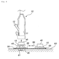
- Fig. 1 is a schematic diagram of inflator thermally treating equipment comprising a thermally treating tower
- Fig. 2 is a process diagram illustrating the treatment method of the present invention
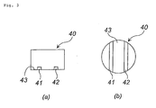
- Fig. 3 (a) and (b) are a front view and a plan view of a bucket, respectively.
- an inflator 30 is treated to be activated in the interior of a thermally treating tower 10 by subjecting the inflator 30 to high-temperature treatment at a temperature that is equal to or greater than the temperature required to ignite and burn the gas generating agent installed in the inflator 30.
- the inflator 30 serving as the treatment subject is introduced through an inflator introducing port 12 into a bucket 40 placed on a floor portion 15 of the thermally treating tower 10. Note that each constitutional component, including the thermally treating tower 10, is supported by a support structure not shown in the drawing.
- the bucket 40 is formed to match the inner form of the thermally treating tower 10, and therefore the inner diameter of the thermally treating tower 10 and the outer diameter of the bucket 40 are preferably similar.
- the inflator 30 can be prevented from slipping between the inner wall surface of the thermally treating tower 10 and the outer wall surface of the bucket 40. Moreover, damage to the inner wall surface of the thermally treating tower 10 and insufficient heating of the inflator 30 (such that unburned gas generating agent remains in the inflator 30) can be prevented.
- the bucket 40 preferably comprises two insertion holes 41, 42 formed in the diametrical direction on a bottom portion 43 thereof to facilitate post-processing.
- the bucket 40 can be moved using a forklift, for example, by inserting the two claws of the forklift into the two insertion holes 41, 42, and hence, using the bucket 40 constituted in this manner, the safety of an operation to treat the high-temperature bucket 40 can be increased, leading to improvements in workability and treatment efficiency.
- the floor portion 15 of the thermally treating tower 10 is severed from the main body (the thermally treating tower 10 apart from the floor portion 15) so as to be elevatable in a vertical direction. Note, however, that when the floor portion 15 is connected to the main body to form the thermally treating tower 10, the floor portion 15 and main body are connected such that heat cannot escape from the connecting part.
- the interior of the thermally treating tower 10 is maintained at a predetermined temperature (the ignition temperature of the gas generating agent installed in the inflator 30) by a combustion furnace 14 (burner) annexed to the thermally treating tower 10.
- a combustion furnace 14 the combustion furnace 14 (burner) annexed to the thermally treating tower 10.
- kerosene is supplied to the combustion furnace (a combination of a high-calorie burner and a low-calorie burner, for example) 14 as a fuel.
- the temperature at which the gas generating agent burns is equal to or greater than the ignition temperature of the gas generating agent, and this ignition temperature differs according to the composition of the gas generating agent.
- the ignition temperature of a typical gas generating agent is approximately 150 to 500°C, but at excessively high temperatures, the inner wall of the thermally treating tower 10 may be damaged, and therefore the internal temperature of the thermally treating tower 10 is preferably in the range of 150 to 800°C, and more preferably in the range of 150 to 700°C.
- the gas generated by treatment of the inflator 30 (the combustion gas of the gas generating agent) is discharged through an exhaust gas tube 16 provided on an upper opening portion side of the thermally treating tower 10.
- the tip end of the exhaust gas tube 16 is connected to a cooling tower tank 18.
- gas passing through the interior of the exhaust gas tube 16 is cooled in a cooling tower 17 by a water spray produced by a cooling shower 19, and then led into water inside the cooling tower tank 18.
- the gas that accumulates in the cooling tower tank 18 is discharged into the atmosphere through a gas discharge tube 26.
- the reference numerals 20, 22, and 24 denote a heat exchanger, a cooler, and a pump, respectively.
- a metal partition wall 11 which exhibits the same action as a device disclosed in Fig. 1 and so on of JP-A No. 11-101422, may be provided inside the thermally treating tower 10.
- the gas pressure generated by combustion of the gas generating agent may propel the inflator 30 such that the inflator 30 flies into the exhaust gas tube 16 and causes damage thereto.
- partition means 25 through which gas can flow are provided between the thermally treating tower 10 and exhaust gas tube 16.
- the partition means 25 are attached removably using a bolt and nut in a flange portion provided on an inner wall surface 10a of the thermally treating tower 10 or an inner wall surface 16a of the exhaust gas tube 16.
- the partition means 25 may employ wire mesh having a large number of holes, punched metal, a metal grating (an iron grating or the like), or a similar device.
- the size of the holes provided in the partition means 25 is set so that gas can pass through, but the inflator 30 or pieces of the broken inflator 30 cannot pass through.
- the diameter of the holes is preferably not more than 150mm, more preferably not more than 100mm, and even more preferably no more than 20mm.
- the holes take another form such as a square form, the length of one side of the holes should be adjusted such that the holes have a similar opening area to that of the circular holes.
- the material of the partition means 25 is preferably selected in consideration of durability in relation to the internal temperature of the thermally treating tower 10, strength to withstand collisions with the inflator 30 over long-term usage, and so on.
- stainless steel, iron, or a similar material may be used.
- the partition means 25 may be provided singly, or in a combination of two or more. When two or more partition means are used in combination, the two or more means are preferably disposed with a gap therebetween.
- partition means 13 are attached removably to the combustion furnace 14 for the same purpose as the partition means 25.
- the partition means 13 may be attached to the combustion furnace 14 in any positions between the combustion furnace 14 and the interior of the thermally treating tower, for example at the opening part of a heated gas outlet duct 14a of the combustion furnace 14, as shown in Fig. 1, or in another position such as the interior of the heated gas outlet duct 14a of the combustion furnace 14.
- the internal temperature of the thermally treating tower 10 is reduced.
- the internal temperature of the thermally treating tower 10 is approximately 450 to 700°C, for example, and it is therefore extremely dangerous to begin removing the inflator 30 immediately. Hence the internal temperature of the thermally treating tower 10 should be reduced. However, an excessively large amount of time is required to reduce the internal temperature of the thermally treating tower 10 to the vicinity of room temperature, which leads to a decrease in treatment efficiency.
- the internal temperature of the thermally treating tower 10 is preferably reduced to 400°C or less, and more preferably between 250 and 400°C in the present invention.
- the carriage 50 takes the form of a square frame such that the four sides of the frame are able to support the floor portion 15 on which the bucket 40 is placed. Note that since the floor portion 15 is still at a high temperature, the carriage 50 is formed from a material that can withstand this high temperature.
- Two rails 55 are laid on a base surface (the disposition surface of the thermally treating tower 10 and so on) 60, and the carriage 50 is provided with wheels which mesh with the rails 55 such that the carriage 50 is capable of movement in a front-back direction (the direction indicated by the double-headed arrow) along the two rails 55 by means of electric power.
- One end side of the elevating means 45 supports the floor portion 15 on a planar support surface (top plate) 46 thereof, and the other end side is fixed inside a recessed portion space 61 (shown in cross-section in Fig. 2) provided in the base surface 60 within the carriage 50 (within the frame forming the carriage).
- a recessed portion space 61 shown in cross-section in Fig. 2
- the elevating means 45 are elevated to a maximum limit, the floor portion 15 is joined perfectly to the main body of the thermally treating tower 10, and when the elevating means 45 are lowered to a maximum limit, the floor portion 15 is separated automatically from the support surface 46 and placed within the frame of the carriage 50. Further, when the elevating means 45 are lowered to the maximum limit, the elevating means 45 are accommodated completely within the recessed portion space 61 provided in the base surface 60, and therefore do not obstruct movement of the carriage 50.
- any method may be applied as long as the main body and floor portion 15 can be joined perfectly and the efficiency of the high-temperature treatment inside the thermally treating tower 10 is not affected adversely.
- a method may be applied whereby a flange is provided on the opening portion of the main body of the thermally treating tower 10 (the opening portion which appears when the floor portion 15 is lowered), and another flange which corresponds to this flange in both form and size is provided on the outer peripheral edge of the floor portion 15.
- the joint part is fastened by a plurality of clamps attached to the floor portion 15.
- an operation to unfasten the clamps should be performed to lower the floor portion 15.
- the carriage 50 preferably comprises an electric driving device (motor) so that the carriage 50 can travel automatically in accordance with an operation or the like performed by an operator.
- means for stopping the carriage 50 in the predetermined position there are no particular limitations on means for stopping the carriage 50 in the predetermined position.
- a carriage stopping switch a proximity switch, for example
- the predetermined position is preferably set at a sufficient distance from the thermally treating tower 10 so that the operator is not affected adversely by the heat of the thermally treating tower 10.
- the inflator 30 can be recovered at a remove from the high-temperature thermally treating tower 10, and hence the safety of the operation is ensured. Moreover, since the heat of the thermally treating tower 10 is unlikely to have an effect, the time required to reduce the temperature inside the thermally treating tower 10 can be shortened. In other words, the heat reduction span can be reduced, and hence the treatment time can be shortened.
- the temperature of the bucket 40 is still high, and therefore a forklift is used by inserting the two claws of the forklift into the insertion holes 41, 42 of the bucket 40, raising the bucket 40 from the floor portion 15, and then recovering the inflator 30.
- the efficiency of this process is greatly improved. Moreover, since the inflator 30 can be recovered at a remove from the thermally treating tower 10, a sufficient operating space can be secured for the forklift, thereby preventing damage to peripheral equipment.
- the bucket 40 from which the inflator 30 has been recovered, may be returned to the floor portion 15 as is, or in order to increase the treatment efficiency, the bucket 40 carrying the treated inflator 30 may be replaced with a new, empty bucket 40.
- the carriage 50 on which the floor portion 15 is placed, the floor portion 15 carrying the bucket 40 from which the treated inflator 30 has been recovered (or the new, empty bucket 40), is caused to travel to a position directly beneath the thermally treating tower 10.
- the elevating means 45 are used to raise the floor portion 15 to its maximum limit such that the floor portion 15 is attached to the main body of the thermally treating tower 10.
- the inflator 30 is then introduced into the bucket 40 through the inflator introducing port 12, whereupon the high-temperature treatment inside the thermally treating tower 10 is resumed.
- the recovered inflator 30 is passed to a process for recovering and reusing valuable resources, where the metals forming the outer shell and so on of the inflator 30 are recovered according to metal type and reused.
- the thermally treating equipment shown in Fig. 1 was used. First, a wire harness connected to the igniter of the inflator was removed as preliminary treatment. When the wire harness is connected directly to the inflator, the wire harness is cut at its root by scissors or nippers, and when the wire harness is connected to the inflator via a connector, the connector is extracted using an extraction jig. Simultaneously, plastic components were also removed.
- recovered inflators were separated into forms and the main metals (aluminum, iron, stainless steel) constituting the outer shell container thereof.
- an inflator for a driving side (having a disk form with a diameter of approximately 70mm and a thickness of approximately 28mm; the housing thereof is formed from stainless steel with a melting point between 1450 and 1650°C; the inflator contains 40g of gas generating agent with an ignition temperature of 223°C) was subjected to high-temperature treatment in the following manner.
- the combustion furnace 14 was operated, whereby the internal temperature of the thermally treating tower 10 was raised in advance to, and maintained at, approximately 510°C.
- twenty inflators 30 were introduced into the bucket 40 (as shown in Fig. 3, having the form of a bottomed cylinder with the outer diameter of 1.518m; manufactured in SUS304 by Kawakami Tekkou K.K.) of the thermally treating tower 10 (inner diameter 1.56m) through the inflator introducing port 12.
- the internal temperature of the thermally treating tower 10 was maintained at 510°C for approximately 20 to 25 minutes.
- the gas generating agent in the inflators 30 was ignited and burned, and the gas produced by this combustion was discharged to the cooling tower 17 through the exhaust gas tube 16.
- the gas was cooled by a water spray produced by the cooling shower 19, and then led into the water inside the cooling tower tank 18.
- the accumulated gas inside the cooling tower tank 18 was discharged into the atmosphere through the gas discharge tube 26.
- the temperature of the gas at the time of discharge was approximately 50°C.
- the dioxin concentration thereof was found to be no more than 0.25ng-TEQ/Nm 3 .
- Analysis was performed in accordance with the "Dioxins Measurement Manual In Waste Matter Treatment", prepared by the Waste Management Section of the Water Supply and Environmental Sanitation Department in the Environmental Health Bureau of the Japanese Ministry of Health and Welfare.
- the thermally treating tower 10 was left to stand for twelve minutes with heating by the combustion furnace 14 halted, whereby the internal temperature of the thermally treating tower 10 fell from 510°C to 390°C.
- the elevating means 45 were lowered by the maximum limit (approximately 1.1m) such that the floor portion 15 carrying the bucket 40 was placed on the carriage 50 (made of steel (by Suehiro Industries Ltd.) and taking a rectangular frame shape with a short side of 2.5m, a long side of 3m, and a height of 0.34m).
- the carriage 50 was caused to travel automatically along the two rails 55, and halted in a position (removed from the thermally treating tower 10 by a distance of approximately 4m) at which the safety of the operator could be ensured.
- the bucket 40 (shown in Fig. 3) containing the treated inflators 30 and still at a high temperature was lifted up from the floor portion 15 using one forklift, and a new bucket 40 was placed on the floor portion 15 using another forklift.
- the carriage 50 was caused to travel automatically, and halted directly beneath the thermally treating tower 10.
- the elevating means 45 were then raised to their maximum limit such that the floor portion 15 carrying the empty bucket 40 was fitted perfectly into the main body of the thermally treating tower 10. The high-temperature treatment process was then resumed.
- the time required to attach the floor portion 15 to the main body of the thermally treating tower 10 following completion of the cooling process was approximately five minutes, and the time required to raise the internal temperature of the thermally treating tower 10 to 460°C in order to resume the high-temperature treatment was eight minutes.
Landscapes
- Engineering & Computer Science (AREA)
- Environmental & Geological Engineering (AREA)
- Mechanical Engineering (AREA)
- General Engineering & Computer Science (AREA)
- Processing Of Solid Wastes (AREA)
- Air Bags (AREA)
- Gasification And Melting Of Waste (AREA)
- Feeding, Discharge, Calcimining, Fusing, And Gas-Generation Devices (AREA)
Applications Claiming Priority (5)
| Application Number | Priority Date | Filing Date | Title |
|---|---|---|---|
| JP2003037714 | 2003-02-17 | ||
| JP2003037714 | 2003-02-17 | ||
| JP2003077056A JP2004305790A (ja) | 2003-02-17 | 2003-03-20 | インフレータ処理方法 |
| JP2003077056 | 2003-03-20 | ||
| PCT/JP2003/016852 WO2004072549A1 (ja) | 2003-02-17 | 2003-12-26 | インフレータ処理方法 |
Publications (1)
| Publication Number | Publication Date |
|---|---|
| EP1596129A1 true EP1596129A1 (de) | 2005-11-16 |
Family
ID=32871197
Family Applications (1)
| Application Number | Title | Priority Date | Filing Date |
|---|---|---|---|
| EP03768284A Withdrawn EP1596129A1 (de) | 2003-02-17 | 2003-12-26 | Behandlungsverfahren für gasgenerator |
Country Status (4)
| Country | Link |
|---|---|
| US (1) | US20060162829A1 (de) |
| EP (1) | EP1596129A1 (de) |
| JP (1) | JP2004305790A (de) |
| WO (1) | WO2004072549A1 (de) |
Families Citing this family (1)
| Publication number | Priority date | Publication date | Assignee | Title |
|---|---|---|---|---|
| US10428713B2 (en) | 2017-09-07 | 2019-10-01 | Denso International America, Inc. | Systems and methods for exhaust heat recovery and heat storage |
Family Cites Families (4)
| Publication number | Priority date | Publication date | Assignee | Title |
|---|---|---|---|---|
| CA2006139C (en) * | 1989-12-20 | 1995-08-29 | Robert A. Ritter | Lined hazardous waste incinerator |
| JP3269216B2 (ja) * | 1993-10-01 | 2002-03-25 | 豊田合成株式会社 | マイクロ波加熱分解炉 |
| JP3905610B2 (ja) * | 1997-09-29 | 2007-04-18 | ダイセル化学工業株式会社 | インフレータ処理装置およびインフレータ投入判定方法 |
| JPH11304130A (ja) * | 1998-04-24 | 1999-11-05 | Toyota Motor Corp | インフレータ処理装置 |
-
2003
- 2003-03-20 JP JP2003077056A patent/JP2004305790A/ja not_active Withdrawn
- 2003-12-26 EP EP03768284A patent/EP1596129A1/de not_active Withdrawn
- 2003-12-26 WO PCT/JP2003/016852 patent/WO2004072549A1/ja not_active Ceased
- 2003-12-26 US US10/545,602 patent/US20060162829A1/en not_active Abandoned
Non-Patent Citations (1)
| Title |
|---|
| See references of WO2004072549A1 * |
Also Published As
| Publication number | Publication date |
|---|---|
| WO2004072549A1 (ja) | 2004-08-26 |
| JP2004305790A (ja) | 2004-11-04 |
| US20060162829A1 (en) | 2006-07-27 |
Similar Documents
| Publication | Publication Date | Title |
|---|---|---|
| ES2116621T3 (es) | Procedimiento para reducir las emisiones de substancias toxicas de un motor diesel con un catalizador de oxidacion instalado aguas abajo. | |
| KR101569885B1 (ko) | 폐기 매연저감필터의 클리닝을 위한 재생장치와 재생 방법 | |
| CA2029099C (en) | Method and apparatus for cooling, neutralizing, and removing suspended particulates from the gaseous products of combustion and for improving the efficiency of any furnace to which said apparatus is attached ("the kagi scrubber") | |
| EP1596129A1 (de) | Behandlungsverfahren für gasgenerator | |
| CN208872143U (zh) | 余热回收装置 | |
| KR102513568B1 (ko) | 재활용을 위한 전기차 모터의 하우징과 고정자 분리장치 | |
| KR101532773B1 (ko) | 하이브리드 바이오가스 및 악취 혼합 소각연소장치 | |
| EP1595826A1 (de) | Automatisches gasgeneratorladesystem | |
| JP2005024224A (ja) | 汚染土壌浄化装置 | |
| JP4434673B2 (ja) | 排ガス処理方法 | |
| CN218379444U (zh) | 一种安全型催化燃烧设备 | |
| CN212417509U (zh) | 新型燃烧废气氮氧化物低温催化处理设备 | |
| KR102775589B1 (ko) | 유해가스 저감 경유차의 dpf필터 클리닝장치 | |
| JP7011855B2 (ja) | ゴムクローラの廃棄処理方法および廃棄処理装置 | |
| EP1586387A1 (de) | Heissverarbeitungsanlage für gasgeneratoren | |
| CN222238608U (zh) | 新能源汽车动力电池起火的专用降温装置 | |
| JPS629656B2 (de) | ||
| CN216079806U (zh) | 一种垃圾燃烧装置 | |
| CN219367652U (zh) | 一种voc气体处理设备 | |
| KR102847700B1 (ko) | 내열 대차를 이용한 화재 차량 제거 및 소화 시스템 및 방법 | |
| WO2014054006A1 (en) | Incinerator for burning explosive material | |
| CN219966592U (zh) | 一种移动式龙门剪剪切机 | |
| CN211575149U (zh) | 一种有机废气催化燃烧设备 | |
| JP2010138333A (ja) | 廃タイヤ油化装置 | |
| KR200335741Y1 (ko) | 재생식 매연 포집기 |
Legal Events
| Date | Code | Title | Description |
|---|---|---|---|
| PUAI | Public reference made under article 153(3) epc to a published international application that has entered the european phase |
Free format text: ORIGINAL CODE: 0009012 |
|
| 17P | Request for examination filed |
Effective date: 20050816 |
|
| AK | Designated contracting states |
Kind code of ref document: A1 Designated state(s): AT BE BG CH CY CZ DE DK EE ES FI FR GB GR HU IE IT LI LU MC NL PT RO SE SI SK TR |
|
| AX | Request for extension of the european patent |
Extension state: AL LT LV MK |
|
| DAX | Request for extension of the european patent (deleted) | ||
| RBV | Designated contracting states (corrected) |
Designated state(s): DE FR |
|
| RAP1 | Party data changed (applicant data changed or rights of an application transferred) |
Owner name: DAICEL CHEMICAL INDUSTRIES, LTD. |
|
| STAA | Information on the status of an ep patent application or granted ep patent |
Free format text: STATUS: THE APPLICATION HAS BEEN WITHDRAWN |
|
| 18W | Application withdrawn |
Effective date: 20101019 |