Technical Field of the Invention
The present invention relates to an inflator
treatment method for disposal using inflator thermally
treating equipment.
Prior Art
In recent years, the number of new cars equipped with
air bags has increased, and hence in the future, the amount
of inflators installed with gas generating agents that are
produced during disposal of such cars equipped with air
bags will rise. Therefore, from the viewpoints of safety
and effective utilization of resources, it is necessary
to activate the gas generating agent safely to recover
metals and the like therefrom. In such circumstances,
recovery/disposal systems for air bag inflators have begun
to be developed.
To treat an air bag inflator, a method of subjecting
the inflator to thermal treatment inside a thermally
treating tower and activating the gas generating agent
installed in the inflator at a high temperature is applied.
The combustion gas generated by treatment of the gas
generating agent is discharged through an exhaust gas tube
connected to the thermally treating tower.
Following the thermal treatment, the inflator is
removed from the thermally treating tower and subjected
to metal-recovery processing, but since the interior of
the thermally treating tower is at a high temperature,
there is danger involved in recovering the treated
inflator from the thermally treating tower. While
reducing the internal temperature of the thermally
treating tower to ambient temperature is beneficial in
terms of safety, but since the temperature must be raised
again during the subsequent treatment process, this
temperature reduction leads to a dramatic decrease in
thermal efficiency and an increase in cost.
It is therefore desirable to develop a method of
recovering a treated inflator from the interior of a
thermally treating tower with no decrease in safety and
treatment efficiency.
JP-A No. 11-101422 may be cited as prior art relating
to the present invention.
Summary of the Invention
An object of the present invention is to provide an
inflator treatment method for disposal using inflator
thermally treating equipment, with which an inflator can
be treated safely and efficiently, and valuable resources
can be recovered easily from the post-treatment inflator.
As means for achieving this object, an invention of
claim 1 provides an inflator treatment method for disposal
using inflator thermally treating equipment with which an
inflator for an air bag can be subjected to a high-temperature
treatment inside a thermally treating tower,
the inflator treatment method for disposal comprising the
steps of:
As further means for achieving the object, an
invention of claim 2 provides an inflator treatment method
for disposal using inflator thermally treating equipment
with which an inflator for an air bag can be subjected to
a high-temperature treatment inside a thermally treating
tower, the inflator treatment method for disposal
comprising the steps of:
The air bag inflator which serves as the treatment
subject of the present invention includes all inflators
that need to be treated for a variety of reasons, for
example defective goods produced during the manufacturing
process, returned goods from the automobile maker or
module maker, inventory goods that are no longer in
production, and inflators removed from discarded
vehicles.
According to the inflator treatment method for
disposal of the present invention, the operation time can
be reduced greatly, and the safety of the operation can
be improved.
Brief Description of the Drawings
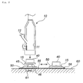
Fig. 1 is a schematic diagram of thermally treating
equipment to which a treatment method of the present
invention is applied;
Fig. 2 is a process diagram illustrating the
treatment method of the present invention; and
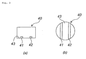
In Fig. 3, Fig. 3 (a) is a front view of a bucket and
Fig. 3(b) is a plan view of a bucket.
Explanation of Numerals
- 10
- thermally treating tower
- 30
- inflator
- 40
- bucket
- 45
- elevating means
- 50
- carriage
- 55
- rails
Preferred Embodiments of the Invention
An embodiment of the present invention will now be
described with reference to the drawings. Fig. 1 is a
schematic diagram of inflator thermally treating
equipment comprising a thermally treating tower, Fig. 2
is a process diagram illustrating the treatment method of
the present invention, and Fig. 3 (a) and (b) are a front
view and a plan view of a bucket, respectively.
First, an inflator 30 is treated to be activated in
the interior of a thermally treating tower 10 by subjecting
the inflator 30 to high-temperature treatment at a
temperature that is equal to or greater than the
temperature required to ignite and burn the gas generating
agent installed in the inflator 30.
The inflator 30 serving as the treatment subject is
introduced through an inflator introducing port 12 into
a bucket 40 placed on a floor portion 15 of the thermally
treating tower 10. Note that each constitutional
component, including the thermally treating tower 10, is
supported by a support structure not shown in the drawing.
The bucket 40 is formed to match the inner form of
the thermally treating tower 10, and therefore the inner
diameter of the thermally treating tower 10 and the outer
diameter of the bucket 40 are preferably similar.
Thus the inflator 30 can be prevented from slipping
between the inner wall surface of the thermally treating
tower 10 and the outer wall surface of the bucket 40.
Moreover, damage to the inner wall surface of the thermally
treating tower 10 and insufficient heating of the inflator
30 (such that unburned gas generating agent remains in the
inflator 30) can be prevented.
As shown in Fig. 3 (a) and (b), the bucket 40
preferably comprises two insertion holes 41, 42 formed in
the diametrical direction on a bottom portion 43 thereof
to facilitate post-processing.
The bucket 40 can be moved using a forklift, for
example, by inserting the two claws of the forklift into
the two insertion holes 41, 42, and hence, using the bucket
40 constituted in this manner, the safety of an operation
to treat the high-temperature bucket 40 can be increased,
leading to improvements in workability and treatment
efficiency.
The floor portion 15 of the thermally treating tower
10 is severed from the main body (the thermally treating
tower 10 apart from the floor portion 15) so as to be
elevatable in a vertical direction. Note, however, that
when the floor portion 15 is connected to the main body
to form the thermally treating tower 10, the floor portion
15 and main body are connected such that heat cannot escape
from the connecting part.
When the inflator 30 is introduced, the interior of
the thermally treating tower 10 is maintained at a
predetermined temperature (the ignition temperature of
the gas generating agent installed in the inflator 30) by
a combustion furnace 14 (burner) annexed to the thermally
treating tower 10. Note that kerosene is supplied to the
combustion furnace (a combination of a high-calorie burner
and a low-calorie burner, for example) 14 as a fuel.
The temperature at which the gas generating agent
burns is equal to or greater than the ignition temperature
of the gas generating agent, and this ignition temperature
differs according to the composition of the gas generating
agent. The ignition temperature of a typical gas
generating agent is approximately 150 to 500°C, but at
excessively high temperatures, the inner wall of the
thermally treating tower 10 may be damaged, and therefore
the internal temperature of the thermally treating tower
10 is preferably in the range of 150 to 800°C, and more
preferably in the range of 150 to 700°C.
The gas generated by treatment of the inflator 30
(the combustion gas of the gas generating agent) is
discharged through an exhaust gas tube 16 provided on an
upper opening portion side of the thermally treating tower
10.
The tip end of the exhaust gas tube 16 is connected
to a cooling tower tank 18. Hence, gas passing through
the interior of the exhaust gas tube 16 is cooled in a
cooling tower 17 by a water spray produced by a cooling
shower 19, and then led into water inside the cooling tower
tank 18. The gas that accumulates in the cooling tower
tank 18 is discharged into the atmosphere through a gas
discharge tube 26. The reference numerals 20, 22, and 24
denote a heat exchanger, a cooler, and a pump, respectively.
Note that a metal partition wall 11, which exhibits the
same action as a device disclosed in Fig. 1 and so on of
JP-A No. 11-101422, may be provided inside the thermally
treating tower 10.
When the inflator 30 is treated to be activated, the
gas pressure generated by combustion of the gas generating
agent may propel the inflator 30 such that the inflator
30 flies into the exhaust gas tube 16 and causes damage
thereto. To prevent the propelled inflator 30 from flying
into the exhaust gas tube 16, partition means 25 through
which gas can flow are provided between the thermally
treating tower 10 and exhaust gas tube 16.
The partition means 25 are attached removably using
a bolt and nut in a flange portion provided on an inner
wall surface 10a of the thermally treating tower 10 or an
inner wall surface 16a of the exhaust gas tube 16.
The partition means 25 may employ wire mesh having
a large number of holes, punched metal, a metal grating
(an iron grating or the like), or a similar device. The
size of the holes provided in the partition means 25 is
set so that gas can pass through, but the inflator 30 or
pieces of the broken inflator 30 cannot pass through.
There are no particular limitations on the size of
the holes, and when the holes are circular, the diameter
thereof is preferably not more than 150mm, more preferably
not more than 100mm, and even more preferably no more than
20mm. When the holes take another form such as a square
form, the length of one side of the holes should be adjusted
such that the holes have a similar opening area to that
of the circular holes.
The material of the partition means 25 is preferably
selected in consideration of durability in relation to the
internal temperature of the thermally treating tower 10,
strength to withstand collisions with the inflator 30 over
long-term usage, and so on. For example, stainless steel,
iron, or a similar material may be used.
The partition means 25 may be provided singly, or
in a combination of two or more. When two or more partition
means are used in combination, the two or more means are
preferably disposed with a gap therebetween.
Further, partition means 13 are attached removably
to the combustion furnace 14 for the same purpose as the
partition means 25. The partition means 13 may be attached
to the combustion furnace 14 in any positions between the
combustion furnace 14 and the interior of the thermally
treating tower, for example at the opening part of a heated
gas outlet duct 14a of the combustion furnace 14, as shown
in Fig. 1, or in another position such as the interior of
the heated gas outlet duct 14a of the combustion furnace
14.
Once the high-temperature treatment of the inflator
30 is complete, the internal temperature of the thermally
treating tower 10 is reduced.
Immediately after completion of the high-temperature
treatment, the internal temperature of the
thermally treating tower 10 is approximately 450 to 700°C,
for example, and it is therefore extremely dangerous to
begin removing the inflator 30 immediately. Hence the
internal temperature of the thermally treating tower 10
should be reduced. However, an excessively large amount
of time is required to reduce the internal temperature of
the thermally treating tower 10 to the vicinity of room
temperature, which leads to a decrease in treatment
efficiency.
Hence, in consideration of both operational safety
and treatment efficiency, coupled with the fact that
operational safety is high when the treatment method of
the present invention is applied, the internal temperature
of the thermally treating tower 10 is preferably reduced
to 400°C or less, and more preferably between 250 and 400°C
in the present invention.
Next, as shown in Fig. 2, only the floor portion 15
of the thermally treating tower 10, which is separable from
the main body and on which the bucket 40 is placed, is
lowered onto a carriage 50 using elevating means 45.
The carriage 50 takes the form of a square frame such
that the four sides of the frame are able to support the
floor portion 15 on which the bucket 40 is placed. Note
that since the floor portion 15 is still at a high
temperature, the carriage 50 is formed from a material that
can withstand this high temperature.
Two rails 55 are laid on a base surface (the
disposition surface of the thermally treating tower 10 and
so on) 60, and the carriage 50 is provided with wheels which
mesh with the rails 55 such that the carriage 50 is capable
of movement in a front-back direction (the direction
indicated by the double-headed arrow) along the two rails
55 by means of electric power.
One end side of the elevating means 45 supports the
floor portion 15 on a planar support surface (top plate)
46 thereof, and the other end side is fixed inside a
recessed portion space 61 (shown in cross-section in Fig.
2) provided in the base surface 60 within the carriage 50
(within the frame forming the carriage). When the
elevating means 45 are elevated to a maximum limit, the
floor portion 15 is joined perfectly to the main body of
the thermally treating tower 10, and when the elevating
means 45 are lowered to a maximum limit, the floor portion
15 is separated automatically from the support surface 46
and placed within the frame of the carriage 50. Further,
when the elevating means 45 are lowered to the maximum
limit, the elevating means 45 are accommodated completely
within the recessed portion space 61 provided in the base
surface 60, and therefore do not obstruct movement of the
carriage 50.
As regards the joining method of the main body and
floor portion 15 of the thermally treating tower 10, any
method may be applied as long as the main body and floor
portion 15 can be joined perfectly and the efficiency of
the high-temperature treatment inside the thermally
treating tower 10 is not affected adversely. For example,
a method may be applied whereby a flange is provided on
the opening portion of the main body of the thermally
treating tower 10 (the opening portion which appears when
the floor portion 15 is lowered), and another flange which
corresponds to this flange in both form and size is
provided on the outer peripheral edge of the floor portion
15. Then, when the flange on the main body of the thermally
treating tower 10 and the flange on the floor portion 15
have been joined perfectly, the joint part is fastened by
a plurality of clamps attached to the floor portion 15.
When such a joining method is applied, an operation to
unfasten the clamps should be performed to lower the floor
portion 15.
Next, with the floor portion 15 placed on the
carriage 50 and the bucket 40 placed on the floor portion
15, the carriage 50 is caused to travel to a predetermined
position. The carriage 50 preferably comprises an
electric driving device (motor) so that the carriage 50
can travel automatically in accordance with an operation
or the like performed by an operator.
There are no particular limitations on means for
stopping the carriage 50 in the predetermined position.
For example, means may be applied whereby a carriage
stopping switch (a proximity switch, for example) is
buried in the predetermined position within the base
surface 60 such that when the carriage 50 reaches the point
at which the carriage stopping switch is buried, current
supply to the driving device for the carriage 50 is halted,
thereby halting the carriage 50 automatically. To ensure
the safety of the operator, the predetermined position is
preferably set at a sufficient distance from the thermally
treating tower 10 so that the operator is not affected
adversely by the heat of the thermally treating tower 10.
By moving the carriage 50 in this manner, the
inflator 30 can be recovered at a remove from the
high-temperature thermally treating tower 10, and hence
the safety of the operation is ensured. Moreover, since
the heat of the thermally treating tower 10 is unlikely
to have an effect, the time required to reduce the
temperature inside the thermally treating tower 10 can be
shortened. In other words, the heat reduction span can
be reduced, and hence the treatment time can be shortened.
Next, with the floor portion 15 remaining on the
carriage 50, the bucket 40 alone is moved, and the treated
inflator 30 is recovered from the interior of the bucket
40.
The temperature of the bucket 40 is still high, and
therefore a forklift is used by inserting the two claws
of the forklift into the insertion holes 41, 42 of the
bucket 40, raising the bucket 40 from the floor portion
15, and then recovering the inflator 30.
By employing the bucket 40 having the constitution
shown in Fig. 3, the efficiency of this process is greatly
improved. Moreover, since the inflator 30 can be
recovered at a remove from the thermally treating tower
10, a sufficient operating space can be secured for the
forklift, thereby preventing damage to peripheral
equipment.
In this process, the bucket 40, from which the
inflator 30 has been recovered, may be returned to the
floor portion 15 as is, or in order to increase the
treatment efficiency, the bucket 40 carrying the treated
inflator 30 may be replaced with a new, empty bucket 40.
Next, the carriage 50 on which the floor portion 15
is placed, the floor portion 15 carrying the bucket 40 from
which the treated inflator 30 has been recovered (or the
new, empty bucket 40), is caused to travel to a position
directly beneath the thermally treating tower 10. Then,
the elevating means 45 are used to raise the floor portion
15 to its maximum limit such that the floor portion 15 is
attached to the main body of the thermally treating tower
10. The inflator 30 is then introduced into the bucket
40 through the inflator introducing port 12, whereupon the
high-temperature treatment inside the thermally treating
tower 10 is resumed.
The recovered inflator 30 is passed to a process for
recovering and reusing valuable resources, where the
metals forming the outer shell and so on of the inflator
30 are recovered according to metal type and reused.
Example
The present invention will now be described in more
detail on the basis of an example. However, the present
invention is not limited to or by this example.
Example 1
High-temperature treatment process
The thermally treating equipment shown in Fig. 1 was
used. First, a wire harness connected to the igniter of
the inflator was removed as preliminary treatment. When
the wire harness is connected directly to the inflator,
the wire harness is cut at its root by scissors or nippers,
and when the wire harness is connected to the inflator via
a connector, the connector is extracted using an
extraction jig. Simultaneously, plastic components were
also removed.
Next, recovered inflators were separated into forms
and the main metals (aluminum, iron, stainless steel)
constituting the outer shell container thereof.
Next, among the separated inflators, an inflator for
a driving side (having a disk form with a diameter of
approximately 70mm and a thickness of approximately 28mm;
the housing thereof is formed from stainless steel with
a melting point between 1450 and 1650°C; the inflator
contains 40g of gas generating agent with an ignition
temperature of 223°C) was subjected to high-temperature
treatment in the following manner.
The combustion furnace 14 was operated, whereby the
internal temperature of the thermally treating tower 10
was raised in advance to, and maintained at, approximately
510°C. In this temperature atmosphere, twenty inflators
30 were introduced into the bucket 40 (as shown in Fig.
3, having the form of a bottomed cylinder with the outer
diameter of 1.518m; manufactured in SUS304 by Kawakami
Tekkou K.K.) of the thermally treating tower 10 (inner
diameter 1.56m) through the inflator introducing port 12.
Following introduction of the inflators 30, the internal
temperature of the thermally treating tower 10 was
maintained at 510°C for approximately 20 to 25 minutes.
The gas generating agent in the inflators 30 was
ignited and burned, and the gas produced by this combustion
was discharged to the cooling tower 17 through the exhaust
gas tube 16. The gas was cooled by a water spray produced
by the cooling shower 19, and then led into the water inside
the cooling tower tank 18. The accumulated gas inside the
cooling tower tank 18 was discharged into the atmosphere
through the gas discharge tube 26. The temperature of the
gas at the time of discharge was approximately 50°C.
When the gas inside the exhaust gas tube 16 was
extracted and measured, the dioxin concentration thereof
was found to be no more than 0.25ng-TEQ/Nm3. Analysis was
performed in accordance with the "Dioxins Measurement
Manual In Waste Matter Treatment", prepared by the Waste
Management Section of the Water Supply and Environmental
Sanitation Department in the Environmental Health Bureau
of the Japanese Ministry of Health and Welfare.
Cooling process
The thermally treating tower 10 was left to stand
for twelve minutes with heating by the combustion furnace
14 halted, whereby the internal temperature of the
thermally treating tower 10 fell from 510°C to 390°C.
Process for lowering floor portion of thermally
treating tower
The elevating means 45 were lowered by the maximum
limit (approximately 1.1m) such that the floor portion 15
carrying the bucket 40 was placed on the carriage 50 (made
of steel (by Suehiro Industries Ltd.) and taking a
rectangular frame shape with a short side of 2.5m, a long
side of 3m, and a height of 0.34m).
Process for moving carriage
The carriage 50 was caused to travel automatically
along the two rails 55, and halted in a position (removed
from the thermally treating tower 10 by a distance of
approximately 4m) at which the safety of the operator could
be ensured.
Bucket replacement process
The bucket 40 (shown in Fig. 3) containing the
treated inflators 30 and still at a high temperature was
lifted up from the floor portion 15 using one forklift,
and a new bucket 40 was placed on the floor portion 15 using
another forklift.
Process for attaching floor portion and bucket to
thermally treating tower
The carriage 50 was caused to travel automatically,
and halted directly beneath the thermally treating tower
10. The elevating means 45 were then raised to their
maximum limit such that the floor portion 15 carrying the
empty bucket 40 was fitted perfectly into the main body
of the thermally treating tower 10. The high-temperature
treatment process was then resumed.
The time required to attach the floor portion 15 to
the main body of the thermally treating tower 10 following
completion of the cooling process was approximately five
minutes, and the time required to raise the internal
temperature of the thermally treating tower 10 to 460°C
in order to resume the high-temperature treatment was
eight minutes. Hence, the total amount of time required
from the end of high-temperature treatment to the
resumption of high-temperature treatment was found to be
12min+5min+8min=25min.
When the process of moving the carriage was not
performed, a large amount of time was required to perform
the cooling process in order to ensure the safety of the
operator, and hence the total amount of time required from
the end of high-temperature treatment to the resumption
of high-temperature treatment was found to be
approximately ninety minutes.