EP1595786A2 - Method of immobilising hydrocarbons inside submerged containers or of transporting said hydrocarbon to the surface, using the properties of supercritical fluids at a great depth - Google Patents
Method of immobilising hydrocarbons inside submerged containers or of transporting said hydrocarbon to the surface, using the properties of supercritical fluids at a great depth Download PDFInfo
- Publication number
- EP1595786A2 EP1595786A2 EP04705095A EP04705095A EP1595786A2 EP 1595786 A2 EP1595786 A2 EP 1595786A2 EP 04705095 A EP04705095 A EP 04705095A EP 04705095 A EP04705095 A EP 04705095A EP 1595786 A2 EP1595786 A2 EP 1595786A2
- Authority
- EP
- European Patent Office
- Prior art keywords
- hydrocarbon
- fluid
- pressure
- supercritical
- outside
- Prior art date
- Legal status (The legal status is an assumption and is not a legal conclusion. Google has not performed a legal analysis and makes no representation as to the accuracy of the status listed.)
- Withdrawn
Links
Images


Classifications
-
- B—PERFORMING OPERATIONS; TRANSPORTING
- B63—SHIPS OR OTHER WATERBORNE VESSELS; RELATED EQUIPMENT
- B63C—LAUNCHING, HAULING-OUT, OR DRY-DOCKING OF VESSELS; LIFE-SAVING IN WATER; EQUIPMENT FOR DWELLING OR WORKING UNDER WATER; MEANS FOR SALVAGING OR SEARCHING FOR UNDERWATER OBJECTS
- B63C7/00—Salvaging of disabled, stranded, or sunken vessels; Salvaging of vessel parts or furnishings, e.g. of safes; Salvaging of other underwater objects
- B63C7/006—Emptying the contents of sunken, stranded, or disabled vessels, e.g. by engaging the vessel; Underwater collecting of buoyant contents, such as liquid, particulate or gaseous contents, escaping from sunken vessels, e.g. using funnels, or tents for recovery of escaping hydrocarbons
-
- B—PERFORMING OPERATIONS; TRANSPORTING
- B01—PHYSICAL OR CHEMICAL PROCESSES OR APPARATUS IN GENERAL
- B01D—SEPARATION
- B01D11/00—Solvent extraction
- B01D11/04—Solvent extraction of solutions which are liquid
- B01D11/0403—Solvent extraction of solutions which are liquid with a supercritical fluid
- B01D11/0407—Solvent extraction of solutions which are liquid with a supercritical fluid the supercritical fluid acting as solvent for the solute
-
- B—PERFORMING OPERATIONS; TRANSPORTING
- B08—CLEANING
- B08B—CLEANING IN GENERAL; PREVENTION OF FOULING IN GENERAL
- B08B9/00—Cleaning hollow articles by methods or apparatus specially adapted thereto
- B08B9/08—Cleaning containers, e.g. tanks
-
- B—PERFORMING OPERATIONS; TRANSPORTING
- B63—SHIPS OR OTHER WATERBORNE VESSELS; RELATED EQUIPMENT
- B63B—SHIPS OR OTHER WATERBORNE VESSELS; EQUIPMENT FOR SHIPPING
- B63B43/00—Improving safety of vessels, e.g. damage control, not otherwise provided for
- B63B43/02—Improving safety of vessels, e.g. damage control, not otherwise provided for reducing risk of capsizing or sinking
- B63B43/10—Improving safety of vessels, e.g. damage control, not otherwise provided for reducing risk of capsizing or sinking by improving buoyancy
- B63B43/16—Temporary equipment for stopping leaks, e.g. collision mats
Definitions
- the present invention falls within the field of treatment of hydrocarbons or other polluting substances for applications in confinement, extraction and transportation thereof, with implications in maintenance of the environment and of marine salvage. Furthermore, the device designed in the present invention falls within the sector of machinery and mechanical equipment.
- a supercritical fluid is characterised in that, under certain conditions of temperature and pressure, beyond the critical point, it has a behaviour which combines properties of liquids (capacity for dissolving) and gases (very high diffusibility). This phenomenon is used in supercritical extraction, which is usually characterised by a high selectivity towards certain extracts (Extraction with supercritical gases, Chem. Eng. Sci. Vol 36, No. 11, p. 1769, 1981. High Pressure Extraction of oil seed, JACOS, Vol 62, No. 8, 1985).
- the present patent protects a method whose purpose is to modify the chemical composition of the hydrocarbon in the vicinity of the crack by altering its viscosity and/or density, for example enriching it in heavy components, with the aim of halting the flow of hydrocarbon towards the outside, or permitting its deposition on the sea floor, and, in a second level, a modification of this technique with the aim of diminishing the viscosity of the major part of the mass to transport, which would facilitate transportation of the stored crude oil up to the surface, making use of a gasification phenomenon of the supercritical fluid in the evacuation column for the fluid towards the outside.
- a supercritical fluid can alter the physico-chemical properties of the hydrocarbon present in the tank of an oil tanker sunk at a great depth.
- the fluid will behave as a supercritical fluid bearing in mind the pressure conditions existing in this environment.
- an object of the present invention consists of a method for modifying the chemical composition, viscosity and/or density of a hydrocarbon, stored in a container on the sea floor or freshwater floor, with the aim of immobilising it in its interior or of transporting it to the surface, henceforth the method of the present invention, based on the use of a supercritical fluid which is such as a consequence of the pressure conditions existing at the working depth, and consisting of the following steps:
- hydrocarbon refers to crude oil, gasoil, vacuum gasoil, diesel and other derivative components.
- the term “container” refers to hulls of ships, among others, tankers, barges and fuel tanks of the actual ships.
- a further object of the present invention consists of the use of the method thereof and of the device for putting it into practice in sealing cracks and fissures of containers of, among others, oil tankers sunk at sea with hydrocarbons in their interior, with the aim of immobilising and stabilising them in order to prevent their leaking or for transporting or pumping this hydrocarbon to the outside.
- a particular object of the present invention consists of the method thereof where the supercritical fluid is insufflated on a portion of the hydrocarbon in the vicinity of a crack in the hull of a ship, where a selective extraction is performed of the lightest fractions, thereby enriching the hydrocarbon in its heaviest fractions. This would cause the crack to be sealed when the hydrocarbon mass, in its natural tendency to discharge, pushes this high viscosity portion towards the crack.
- a particular object of the present invention consists of the method thereof where the supercritical fluid is miscible with the lightest, light and heavy fraction and even with the totality of the hydrocarbon, not dissolving it but instead modifying its viscosity bearing in mind the particular characteristics of supercritical fluids, and is applied together with the presence or not of a modifying compound.
- Another particular object of the present invention consists of a method characterised in that, after ducting the mixture towards a pipeline, said mixture is transported towards the outside by the effect of the lower hydrostatic pressure corresponding to the column of fluid present in its interior, with respect to the hydrostatic pressure present on the outside of that pipeline, which generates a suction effect of the crude oil towards the outside (Example 2).
- a particular object of the present invention consists of the method thereof where the supercritical fluid that is used has a similar chemical nature (and therefore encourages the process of extraction or dissolving or emulsifying) to that of the hydrocarbon (or any other substance contained in the tanks).
- This fluid can be, among others, carbon dioxide, ethylene, propylene, oxygen, methane, ethane or mixtures thereof or any other fluid with supercritical behaviour, together with the presence or not of a minority component, habitually known as the modifier.
- the modifier alters the selectivity of the supercritical extraction technique towards the desired products, lighter hydrocarbons, as in the method described further below in Example 1, or encourages the decrease in the viscosity of the greater part of the hydrocarbon mass, as in the method described further below in Example 2.
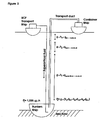
- the heating of the fluid prior to its insufflation in the crack would be carried out by any means currently available, for example and among others, with a heater of the electrical resistance type with mineral insulation, sheathed in a stainless steel casing, supplied with electricity from the mother ship on the surface (see Figure 1). Any other heating method is applicable for heating the supercritical fluid and forms part of the present invention. So, another particular object of this invention consists of the method thereof in which the fluid is heated prior to being insufflated on the hydrocarbon mass.
- Another particular object of the present invention consists of a method thereof where the supercritical fluid used maintains its supercritical characteristics at the pressures and temperatures present in the environment where that method is being carried out, among others for example, on the sea floor with high pressures, without the need to provide heating.
- An object of the present invention consists of a method for refining the specific applications of the method of the present invention and which would comprise at least:
- the quantity of fluid necessary for an immersion will depend on the volume of hydrocarbon to treat. Typically, it could be considered between one and ten stacks of 12 standardised cylinders per immersion, for the possible sealing of a crack, or much higher quantities, which could only be transported by means of other kinds of containers, such as tanker ships, for the treatment of large quantities of crude oil, as would be the case of transporting that oil to the outside.
- the fluid used for these techniques is normally found in the form of liquefied gas or compressed gas, contained in pressurised cylinders on the mother ship.
- a tanker ship can store this fluid in pressurised tanks.
- a pump provided with a refrigerated head or not, or a compressor system, would pump the fluid through a pressure hose of sufficient length (and chemically compatible with the fluid) as far as the interior of the sunken hull.
- the reel or spool for the pressure hose can be fitted with a high-pressure rotary coupling in its central shaft permitting it to be unrolled even when connected to the fluid supply pump or compressor while the latter is being introduced into the ocean, with the aim of having an uninterrupted supply of fluid.
- These operations can also be carried out starting from shorter sections of high-pressure hose joined by means of high-pressure couplings, normally fast type, self-sealing or not.
- reels of smaller size can contain coils of conductor cables for instruments such as the heater, thermocouple, pressure transmitter, etc.
- a high-pressure non-return valve can be installed with an elastomer or metal-metal joint at the end of the hose.
- a diffuser can be installed at the same end ( Figure 1).
- a pressure transducer With the aim of maintaining a higher pressure inside the hose than that existing on the outside, a pressure transducer can be installed. From the reading of its signal, the addition pump can be adjusted so that there is always a slight over-pressure in the line compared to the outside pressure. This fact would also help to prevent the entrance of water into the supply line.
- Another additional object of the present invention consists of the use of the method thereof and of the device for putting it into practice in sealing cracks and fissures of containers of, among others, oil tankers sunk at sea or in lakes with hydrocarbons or other polluting substances in their interior, with the aim of immobilising and stabilising them in order to prevent their leaking or for transporting or assisting the pumping of the hydrocarbon to the outside.
- Example 1 Supercritical extraction process of the light fraction of a crude oil
- a basic supercritical extraction plant (www.icp.csic.es/control/) has been constructed and a supercritical extraction of a hydrocarbon (vacuum gasoil) has been performed, using CO 2 as supercritical fluid on account of its innocuousness.
- the experimental device has consisted of a CO 2 cylinder fitted with a siphon in order to obtain liquid CO 2 at its outlet, a reciprocating positive displacement dosing pump with refrigerated membrane head, a refrigerator for keeping the head of the pump at low temperature, the appropriate valves, a cylindrical receptacle where the gasoil has been stored with heating system, a heated valve for controlling the pressure, a low-pressure separator and a second valve for controlling the pressure, and a third separator at atmospheric pressure.
- CO 2 is supercritical above 74 bar and 31°C.
- An extraction has been carried out with CO 2 on 250 cc of gasoil, without the addition of any modifier, at a pressure of 250 bar and a temperature of 40°C with a flow of 1 I/h of liquid CO 2 for 15 min.
- the ratio of CO 2 used / hydrocarbon confined was 1:1. Any other ratio is feasible for carrying out this process.
- the modified original fraction was difficult to characterise after being withdrawn from the cylinder containing it, due to the fact that in the process of releasing the pressure in the experimental system used, the CO 2 contained in the sample gasified as the pressure dropped and produced a foam (mousse) which contained a large quantity of occluded gas.
- Part of the occluded gas has been extracted using ultrasound in order to release it, previously liquefying the hydrocarbon at 25°C, and the resulting hydrocarbon has a viscosity and melting point that are higher than those of the original, being in the liquid state starting from 19°C unlike the original which is at liquid state from 13°C.
- the extraction of this fraction promoted the desired change in the physical properties of the original hydrocarbon. This change in its viscosity ought to encourage the sealing of the crack.
- the fluid used in this laboratory experiment, CO 2 does not necessarily have to be the most suitable one for promoting this technique, though it is the most innocuous in the laboratory, at the same time as permitting a simple start-up in order to provide an initial confirmation of the technique.
- the method and device sought to be protected consists of using currently available methods (for example, a submarine with an articulated arm, remotely operated robots, etc.) in order to lower a high-pressure line or hose as far as a crack or venthole through which the hydrocarbon is flowing, and to introduce a fluid through it which, in those pressure conditions, presents supercritical behaviour. In order to do this, it can be necessary, though not essential, to heat the insufflation lamp ( Figure 1).
- the fluid chosen should selectively dissolve the lightest fractions present in the hydrocarbon, which will tend to separate out from the heavier, undissolved, fractions owing to the difference in densities.
- the hydrocarbon In the vicinity of the working zone (the crack or exit opening for the crude oil to the outside), the hydrocarbon will become enriched in heavier components and its viscosity and even its density will increase.
- the mass of crude oil present in the tank With its natural tendency to escape through the crack, would push and concentrate the portion of heavy, high viscosity, crude oil in the crack, blocking it up on account of its low capacity for flowing.
- the ocean would act as a reactor owing to the pressure existing at the depth at which the ship or any other kind of container is to be found.
- Example 2. Process for transporting the crude oil as far as the surface
- the effect observed during the depressurisation of the plant can be used for facilitating the transport of the crude oil to the outside, modifying the overall technique with the aim of performing not an extraction but instead an action on the major part of the fractions present in the hydrocarbon with supercritical fluid, modifying its density and viscosity, in order to then make use of the phenomenon of gasification of the supercritical fluid so as to encourage the discharge of the hydrocarbon through a pipeline. Later studies would be able to confirm the feasibility of a technique that permitted the discharge towards the outside of the main mass of the crude oil.
- a supercritical fluid could be used selected for increasing the fluidity of the mass of crude oil, in all its fractions or not. Owing to the lower viscosity and possibly lower density, the crude oil would be encouraged to rise up through the pipeline. Close to the surface, as the pressure drops, gasification of the supercritical fluid used would take place. This gasification, and the consequent formation of foam, could alter the apparent density of the main mass present in the upper part of the communication line and cause it to become lower.
- the hydrostatic pressure at the end of the communication line housed inside the tank (summation of the hydrostatic pressure exerted by each of the sections of different density in that pipeline) could be lower than the hydrostatic pressure acting on the totality of the fluid contained in the tank, as a result of the pressure corresponding to the column of saltwater above it.
- This difference between the pressure to which the main mass contained in the tank is subjected and that existing in the opening of the communication line with the surface, housed inside the tank, together with a lower viscosity in the zone, generated by the input of the supercritical fluid, could cause a suction effect on the main mass towards the surface, which could be exploited for being transported to a container located on the outside.
- the typical density of seawater beneath the layer known as the picnocline is 1.028 g/cc, independently of the temperature and salinity;
- the typical densities of heavy hydrocarbons, depending on the origin of the crude oil and on the fraction being considered can vary between 0.85 and 1.01, typically 09 g/cc;
- the densities of the supercritical fluids, at their critical point usually lie between 0.2 and 0.5 g/cc; though they increase with pressure (in CO 2 for example, reaching a density of 1.0 g/cc at 350 bar and 31°C); there is no data on the apparent density of the mousse formed after gasification of the supercritical fluid, which depends on the nature of the hydrocarbon and on the supercritical fluid used.
- the fluid 25% CH 4 + 75% CO 2 ( Figure 3) has the capacity for diluting the major part of the hydrocarbon and the mixture is supercritical above 0°C and 66 bar, viz., under the working conditions on the sea floor, and without the need for any kind of heating. Data and properties of different supercritical fluids appears in TABLE 1.
- the fluid is mixed with the hydrocarbon (U.S. Patent 3.969.196, 1976.
- Process for the separation of mixtures of substances describes the use of SCF for the extraction of substances from a mixture and it does not come into conflict with the object of this invention) which, due to being more fluid (EP 0506069, 1992, Supercritical Fluids as Diluents in Combustion of Liquid Fuels, describes how the SCFs affect the crude oil lowering its viscosity, and it does not come into conflict with the object of this invention; the following example is cited: a fuel with a viscosity of 10,300 cp at ambient temperature acquires a viscosity of 2,000 cp when heated to 50°C. By adding supercritical CO 2 up to 28% by weight, the viscosity is reduced to 40 cp) and less dense, will start to ascend up the heated drainage hose (a.3.-).
- the linear speed of ascent equivalent to a piston flow in that hose could be 4 m/min (6 cm/sec) (only in the event that the difference in densities were to permit this speed of ascent). So, the ascension of the mixture through a 4000 metre long pipeline would take 16 hr. This time could even be 1 or 2 days. It has to be remembered that, though it is not necessary the heating of the hose would facilitate this process of natural ascension.
- the supercritical fluid When a depth is reached of, for example, and without being restricting, 300 m (the water column present in the hose generates a hydrostatic pressure at this point of 30 bar), the supercritical fluid will go over to its gas phase, being emulsified with the crude oil, until it reaches the surface (the pressure at which the supercritical fluid goes over to its gas phase will depend on, among other causes, the nature of the starting fluids and their composition in the mixture). But then, the height of the hydrostatic column above that hypothetical point situated at a depth of 300 m will not exert a pressure on that point equivalent to 30 bar, since the hydrostatic column p x g x h is generated by an emulsified fluid containing a great quantity of gas.
- a hypothetical equilibrium point is going to be chosen situated 1000 m below sea level, where the forces present in the system, such as the hydrostatic pressure of the column and the pressure loss experienced in the line due to the circulation of the fluid, are in balance.
- the hydrostatic columns of the column SCFliquid + hydrocarbon and SCF + hydrocarbon, situated below the column SCFgas + hydrocarbon, or mousse would have a height of 2500 m altogether, if the ship was located at a depth of, for example, 3500 m.
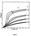
- the density of gasoil of 1.01 g/cc (Le Cedre Report on physical properties of the hydrocarbon present in the Prestige) and of 0.7 g/cc ( Figure 4) for the SCF (for example, 75% CO 2 - 25% CH 4 ), but bearing in mind that during the evacuation process most of the stream will consist of hydrocarbon, the density of that portion of 2500 m of column could be estimated at 0.99 g/cc, for example.
- the hydrostatic pressure generated on the base of the drainage pipeline by this portion of column would be equivalent to 198 bar.
- this pressure will have to be added that corresponding to the portion of column occupied by the emulsion, for which the possibility had been speculated that, in its initial moment, it would consists of a column of 1000 m of density 0.2 g/cc (the density of CO 2 gas is 2 ⁇ 10 -3 , the density of this column will be a function of the quantity of gas dissolved in the hydrocarbon and therefore a function of the flow of SCF provided), and for which a value of 30 bar (for example, because the pressure loss has been borne in mind) has been assumed.
- the pressure loss owing to the circulation of the crude oil through the pipeline could also be considered, which a priori is impossible to determine, but for which any conservative value can be given, for example 50 bar, or any other value, which will be mainly a function of the speed of ascent of the hydrocarbon, of its viscosity, and other parameters.
- the hydrocarbon will appear through the upper opening of the pipeline in its "mousse" form (flashing) and would be deposited in containers in a ship on the surface.
- the supercritical fluid, now gas would be released naturally or forced out of the main hydrocarbon mass.
- the fluids used can be dangerous, for example, and without being restrictive, methane.
- the container tanks would have to be sealed and a burner or equivalent device could be installed at the outlet to the outside (in order to avoid overpressures). The energy generated in this combustion could even be exploited for heating the pipeline by non-electrical means, or for heat exchange with the hydrocarbon stored in the container ship with the aim of releasing the gases more effectively.
- a device has been provided for validation of the procedure at a depth similar to that of the disaster.
- This device would consist of a tank full of crude oil and fitted with appropriate valves and sensors, and with SCF and discharge lines installed on the surface, which could be allowed to descend down to the ocean floor in a controlled manner, in order to then check the validity of the technique with an economic investment substantially lower than that needed for carrying out the extraction procedure on the crude oil stored in the ship.
- This could involve the use of robots or highly sophisticated techniques and methods ( Figure 5).
- the operation of this device could be based on automatic systems controlled from the outside, using pneumatic actuation or not.
- the devices needed for insufflation of the SCF can be similar to those described for the first of the examples, and be fitted with a non-return valve or not, diffuser or not, heater or not, pressure transmitters or not, temperature sensors or not, and the insufflation of the supercritical fluid could be produced inside a cone or funnel which facilitate its mixing with the crude oil or not. No description is made of the means necessary for the work of coupling these devices to the hull of the ship at those depths, but any of those permitted by the current state of the art would be valid.
Landscapes
- Engineering & Computer Science (AREA)
- Mechanical Engineering (AREA)
- Ocean & Marine Engineering (AREA)
- Chemical & Material Sciences (AREA)
- Chemical Kinetics & Catalysis (AREA)
- Production Of Liquid Hydrocarbon Mixture For Refining Petroleum (AREA)
- Physical Or Chemical Processes And Apparatus (AREA)
- Extraction Or Liquid Replacement (AREA)
- Filling Or Discharging Of Gas Storage Vessels (AREA)
Abstract
The invention relates to a method of immobilising a hydrocarbon contained inside a container submerged in the sea floor or of transporting said hydrocarbon to the surface using the pressure gradient between the pressure in the sea floor and the pressure generated at the lower opening of a hydrostatic column in which the fluid used as the supercritical fluid is gasified when same moves to non-extreme pressure conditions. <IMAGE>
Description
The present invention falls within the field of treatment of hydrocarbons
or other polluting substances for applications in confinement, extraction and
transportation thereof, with implications in maintenance of the environment and
of marine salvage. Furthermore, the device designed in the present invention
falls within the sector of machinery and mechanical equipment.
When the viscosity of crude oil or gasoil diesel transported in the tanks of
a ship is not sufficiently high under the conditions in which it is being carried,
and it flows to the outside following an accident at sea, due to the appearance
of cracks or via the actual ventholes of the storage tanks, it has recently been
demonstrated, the technology available for cutting off the leaks has to be
improved or that it is not sufficiently efficient.
A supercritical fluid is characterised in that, under certain conditions of
temperature and pressure, beyond the critical point, it has a behaviour which
combines properties of liquids (capacity for dissolving) and gases (very high
diffusibility). This phenomenon is used in supercritical extraction, which is
usually characterised by a high selectivity towards certain extracts (Extraction
with supercritical gases, Chem. Eng. Sci. Vol 36, No. 11, p. 1769, 1981. High
Pressure Extraction of oil seed, JACOS, Vol 62, No. 8, 1985).
The present patent protects a method whose purpose is to modify the
chemical composition of the hydrocarbon in the vicinity of the crack by altering
its viscosity and/or density, for example enriching it in heavy components, with
the aim of halting the flow of hydrocarbon towards the outside, or permitting its
deposition on the sea floor, and, in a second level, a modification of this
technique with the aim of diminishing the viscosity of the major part of the mass
to transport, which would facilitate transportation of the stored crude oil up to
the surface, making use of a gasification phenomenon of the supercritical fluid
in the evacuation column for the fluid towards the outside.
The use of a supercritical fluid can alter the physico-chemical properties
of the hydrocarbon present in the tank of an oil tanker sunk at a great depth.
The fluid will behave as a supercritical fluid bearing in mind the pressure
conditions existing in this environment.
There are two uses that can be considered starting from this technique
and which are the object of protection of this patent:
The present invention is based on the fact that the inventors have
observed that:
So, an object of the present invention consists of a method for modifying
the chemical composition, viscosity and/or density of a hydrocarbon, stored in a
container on the sea floor or freshwater floor, with the aim of immobilising it in
its interior or of transporting it to the surface, henceforth the method of the
present invention, based on the use of a supercritical fluid which is such as a
consequence of the pressure conditions existing at the working depth, and
consisting of the following steps:
As used in the present invention, the term "hydrocarbon" refers to crude
oil, gasoil, vacuum gasoil, diesel and other derivative components.
As used in the present invention, the term "container" refers to hulls of
ships, among others, tankers, barges and fuel tanks of the actual ships.
A further object of the present invention consists of the use of the method
thereof and of the device for putting it into practice in sealing cracks and
fissures of containers of, among others, oil tankers sunk at sea with
hydrocarbons in their interior, with the aim of immobilising and stabilising them
in order to prevent their leaking or for transporting or pumping this hydrocarbon
to the outside.
A particular object of the present invention consists of the method thereof
where the supercritical fluid is insufflated on a portion of the hydrocarbon in the
vicinity of a crack in the hull of a ship, where a selective extraction is performed
of the lightest fractions, thereby enriching the hydrocarbon in its heaviest
fractions. This would cause the crack to be sealed when the hydrocarbon mass,
in its natural tendency to discharge, pushes this high viscosity portion towards
the crack.
A particular object of the present invention consists of the method thereof
where the supercritical fluid is miscible with the lightest, light and heavy fraction
and even with the totality of the hydrocarbon, not dissolving it but instead
modifying its viscosity bearing in mind the particular characteristics of
supercritical fluids, and is applied together with the presence or not of a
modifying compound. In this way, its fluidity is facilitated and its later exit or
ducting is encouraged towards a pipeline for being transported to the surface,
making use of the generation, in a discharge duct, of a hydrostatic column
which exerts pressure on the base of the duct much lower than that acting on
the hydrocarbon mass stored in the tank, as described in Example 2, with a
suction or chimney effect being created on the crude oil stored in that tank
(Example 2), wherein said method consists of:
and
Another particular object of the present invention consists of a method
characterised in that, after ducting the mixture towards a pipeline, said mixture
is transported towards the outside by the effect of the lower hydrostatic
pressure corresponding to the column of fluid present in its interior, with respect
to the hydrostatic pressure present on the outside of that pipeline, which
generates a suction effect of the crude oil towards the outside (Example 2).
A particular object of the present invention consists of the method thereof
where the supercritical fluid that is used has a similar chemical nature (and
therefore encourages the process of extraction or dissolving or emulsifying) to
that of the hydrocarbon (or any other substance contained in the tanks). This
fluid can be, among others, carbon dioxide, ethylene, propylene, oxygen,
methane, ethane or mixtures thereof or any other fluid with supercritical
behaviour, together with the presence or not of a minority component, habitually
known as the modifier. The modifier alters the selectivity of the supercritical
extraction technique towards the desired products, lighter hydrocarbons, as in
the method described further below in Example 1, or encourages the decrease
in the viscosity of the greater part of the hydrocarbon mass, as in the method
described further below in Example 2.
Furthermore, the technical difficulties most complex to solve would
probably result from the need for heating at those depths so that the fluid could
take on the supercritical condition. The heating of the fluid prior to its insufflation
in the crack (if necessary) would be carried out by any means currently
available, for example and among others, with a heater of the electrical
resistance type with mineral insulation, sheathed in a stainless steel casing,
supplied with electricity from the mother ship on the surface (see Figure 1). Any
other heating method is applicable for heating the supercritical fluid and forms
part of the present invention. So, another particular object of this invention
consists of the method thereof in which the fluid is heated prior to being
insufflated on the hydrocarbon mass.
A detailed laboratory study on the behaviour of different supercritical
fluids, or their mixtures, together with the use of suitable modifiers, could lead to
the development of a method based on supercritical fluids which are such at the
pressures and temperatures present on the sea floor, without providing any
heat. Some supercritical fluids and their critical point can be cited (Encyclopédie
des gaz, Elsevier - L'air Liquide):
| Supercritical fluid | Temperature | Pressure | Density |
| CO2 | TC = 31°C | PC = 74 bar | DC = 0.47 g/cc |
| O2 (compressed gas) | TC = -118°C | PC = 50 bar | DC = 0.43 g/cc |
| Methane (compressed gas) | TC = -82°C | PC = 46 bar | DC = 0.16 g/cc |
| Ethane | TC = 32°C | PC = 49 bar | DC = 0.20 g/cc |
| Ethylene | TC = 35°C | PC = 62 bar | DC = 0.22 g/cc |
Another particular object of the present invention consists of a method
thereof where the supercritical fluid used maintains its supercritical
characteristics at the pressures and temperatures present in the environment
where that method is being carried out, among others for example, on the sea
floor with high pressures, without the need to provide heating.
An object of the present invention consists of a method for refining the
specific applications of the method of the present invention and which would
comprise at least:
The quantity of fluid necessary for an immersion will depend on the
volume of hydrocarbon to treat. Typically, it could be considered between one
and ten stacks of 12 standardised cylinders per immersion, for the possible
sealing of a crack, or much higher quantities, which could only be transported
by means of other kinds of containers, such as tanker ships, for the treatment of
large quantities of crude oil, as would be the case of transporting that oil to the
outside.
The fluid used for these techniques is normally found in the form of
liquefied gas or compressed gas, contained in pressurised cylinders on the
mother ship. For using large quantities, a tanker ship can store this fluid in
pressurised tanks. A pump, provided with a refrigerated head or not, or a
compressor system, would pump the fluid through a pressure hose of sufficient
length (and chemically compatible with the fluid) as far as the interior of the
sunken hull. The reel or spool for the pressure hose can be fitted with a high-pressure
rotary coupling in its central shaft permitting it to be unrolled even
when connected to the fluid supply pump or compressor while the latter is being
introduced into the ocean, with the aim of having an uninterrupted supply of
fluid. These operations can also be carried out starting from shorter sections of
high-pressure hose joined by means of high-pressure couplings, normally fast
type, self-sealing or not.
Other reels of smaller size can contain coils of conductor cables for
instruments such as the heater, thermocouple, pressure transmitter, etc.
An evolution of these technologies, the development of them, or the use
of high-selectivity fluids, together with suitable modifiers, could permit the
system to be installed even in the interior of a small submarine, for example,
which would enormously facilitate the use of this technique for the tasks of
sealing cracks.
It can be necessary to prevent water entering the fluid feed line and in
order to do this a high-pressure non-return valve can be installed with an
elastomer or metal-metal joint at the end of the hose. A diffuser can be installed
at the same end (Figure 1). With the aim of maintaining a higher pressure inside
the hose than that existing on the outside, a pressure transducer can be
installed. From the reading of its signal, the addition pump can be adjusted so
that there is always a slight over-pressure in the line compared to the outside
pressure. This fact would also help to prevent the entrance of water into the
supply line.
Finally, another additional object of the present invention consists of the
use of the method thereof and of the device for putting it into practice in sealing
cracks and fissures of containers of, among others, oil tankers sunk at sea or in
lakes with hydrocarbons or other polluting substances in their interior, with the
aim of immobilising and stabilising them in order to prevent their leaking or for
transporting or assisting the pumping of the hydrocarbon to the outside.
A basic supercritical extraction plant (www.icp.csic.es/control/) has
been constructed and a supercritical extraction of a hydrocarbon (vacuum
gasoil) has been performed, using CO2 as supercritical fluid on account of its
innocuousness.
The experimental device has consisted of a CO2 cylinder fitted with a
siphon in order to obtain liquid CO2 at its outlet, a reciprocating positive
displacement dosing pump with refrigerated membrane head, a refrigerator for
keeping the head of the pump at low temperature, the appropriate valves, a
cylindrical receptacle where the gasoil has been stored with heating system, a
heated valve for controlling the pressure, a low-pressure separator and a
second valve for controlling the pressure, and a third separator at atmospheric
pressure.
CO2 is supercritical above 74 bar and 31°C. An extraction has been
carried out with CO2 on 250 cc of gasoil, without the addition of any modifier, at
a pressure of 250 bar and a temperature of 40°C with a flow of 1 I/h of liquid
CO2 for 15 min. The ratio of CO2 used / hydrocarbon confined was 1:1. Any
other ratio is feasible for carrying out this process.
The experimental technique has consisted of:
As a result of this extraction, a light fraction of gasoil (fluid and with a
pale yellow colour) has been obtained in the separators, at a quantity of 4 cc.
The modified original fraction was difficult to characterise after being
withdrawn from the cylinder containing it, due to the fact that in the process of
releasing the pressure in the experimental system used, the CO2 contained in
the sample gasified as the pressure dropped and produced a foam (mousse)
which contained a large quantity of occluded gas.
Part of the occluded gas has been extracted using ultrasound in order to
release it, previously liquefying the hydrocarbon at 25°C, and the resulting
hydrocarbon has a viscosity and melting point that are higher than those of the
original, being in the liquid state starting from 19°C unlike the original which is at
liquid state from 13°C. The extraction of this fraction promoted the desired
change in the physical properties of the original hydrocarbon. This change in its
viscosity ought to encourage the sealing of the crack. The fluid used in this
laboratory experiment, CO2, does not necessarily have to be the most suitable
one for promoting this technique, though it is the most innocuous in the
laboratory, at the same time as permitting a simple start-up in order to provide
an initial confirmation of the technique.
Under the real application conditions of this method for sealing
hydrocarbon leaks on the sea floor, the phenomenon of "gasification" in the
hydrocarbon will not take place since no such depressurisation exists, and the
hydrocarbon mass, concentrated in heavy fractions, will behave in accordance
with the physico-chemical properties of its new composition. In the zone of
sinking of a ship, the pressure is high (it increases approximately 1 bar for every
10 m in depth).
The method and device sought to be protected consists of using currently
available methods (for example, a submarine with an articulated arm, remotely
operated robots, etc.) in order to lower a high-pressure line or hose as far as a
crack or venthole through which the hydrocarbon is flowing, and to introduce a
fluid through it which, in those pressure conditions, presents supercritical
behaviour. In order to do this, it can be necessary, though not essential, to heat
the insufflation lamp (Figure 1). The fluid chosen should selectively dissolve the
lightest fractions present in the hydrocarbon, which will tend to separate out
from the heavier, undissolved, fractions owing to the difference in densities. In
the vicinity of the working zone (the crack or exit opening for the crude oil to the
outside), the hydrocarbon will become enriched in heavier components and its
viscosity and even its density will increase. When the input of supercritical fluid
stops, the mass of crude oil present in the tank, with its natural tendency to
escape through the crack, would push and concentrate the portion of heavy,
high viscosity, crude oil in the crack, blocking it up on account of its low capacity
for flowing.
For the purpose of the methods or processes that are protected with this
patent, the ocean would act as a reactor owing to the pressure existing at the
depth at which the ship or any other kind of container is to be found.
The effect observed during the depressurisation of the plant can be used
for facilitating the transport of the crude oil to the outside, modifying the overall
technique with the aim of performing not an extraction but instead an action on
the major part of the fractions present in the hydrocarbon with supercritical fluid,
modifying its density and viscosity, in order to then make use of the
phenomenon of gasification of the supercritical fluid so as to encourage the
discharge of the hydrocarbon through a pipeline. Later studies would be able to
confirm the feasibility of a technique that permitted the discharge towards the
outside of the main mass of the crude oil.
This technique would consist of the following: in the submerged end of a
communication line, or pipeline, between the container and the surface, a
supercritical fluid could be used selected for increasing the fluidity of the mass
of crude oil, in all its fractions or not. Owing to the lower viscosity and possibly
lower density, the crude oil would be encouraged to rise up through the pipeline.
Close to the surface, as the pressure drops, gasification of the supercritical fluid
used would take place. This gasification, and the consequent formation of foam,
could alter the apparent density of the main mass present in the upper part of
the communication line and cause it to become lower. In this case, the
hydrostatic pressure at the end of the communication line housed inside the
tank (summation of the hydrostatic pressure exerted by each of the sections of
different density in that pipeline) could be lower than the hydrostatic pressure
acting on the totality of the fluid contained in the tank, as a result of the pressure
corresponding to the column of saltwater above it. This difference between the
pressure to which the main mass contained in the tank is subjected and that
existing in the opening of the communication line with the surface, housed
inside the tank, together with a lower viscosity in the zone, generated by the
input of the supercritical fluid, could cause a suction effect on the main mass
towards the surface, which could be exploited for being transported to a
container located on the outside.
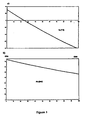
This is represented graphically in Figure 2, where P1 is the hydrostatic
pressure to which the tank is subjected, and P2 is the hydrostatic pressure at
the lower opening of the pipeline.
These considerations are based on the following data: the typical density
of seawater beneath the layer known as the picnocline is 1.028 g/cc,
independently of the temperature and salinity; the typical densities of heavy
hydrocarbons, depending on the origin of the crude oil and on the fraction being
considered, can vary between 0.85 and 1.01, typically 09 g/cc; the densities of
the supercritical fluids, at their critical point, usually lie between 0.2 and 0.5
g/cc; though they increase with pressure (in CO2 for example, reaching a
density of 1.0 g/cc at 350 bar and 31°C); there is no data on the apparent
density of the mousse formed after gasification of the supercritical fluid, which
depends on the nature of the hydrocarbon and on the supercritical fluid used.
One method for carrying out the operation of extracting the crude oil to
the outside could consist of the following, though without this restricting the
scope of this invention and citing it only by way of example:
and
This supercritical fluid is not selected with the intention of carrying out an
extraction or selective separation (as in Example 1), nor with the aim of
dissolving the major part of the hydrocarbon (U.S. Patent 4.532.992, 1985,
Method for recovering petroleum, describes the use of SCF for the extraction of
crude oil from exhausted oil wells, dissolving the crude oil with supercritical
fluid, and it does not come into conflict with the object of this invention, U.S.
Patent 4.446.921, 1984, Method for Underground Gasification of Solid Fuel,
describes a method based on the use of SCF for the extraction of crude oil from
solid deposits, dissolving the crude oil with supercritical fluid, and it does not
come into conflict with the object of this invention). It has been selected with the
aim of modifying the viscosity of the hydrocarbon by means of a small
proportion thereof, and mainly so that, once the suction effect due to the
chimney effect starts, the addition of the supercritical fluid permit the right level
of gasified column (as described later on), and therefore the gradient of suction
force, to be maintained. Moreover, it is chosen with the intention of it is being
supercritical at the pressure and temperature existing at the depth of a
hypothetical sunken hydrocarbon container, in other words, 370 bar and 2°C in
the case of 3600 metres.
For example, the fluid 25% CH4 + 75% CO2 (Figure 3) has the capacity
for diluting the major part of the hydrocarbon and the mixture is supercritical
above 0°C and 66 bar, viz., under the working conditions on the sea floor, and
without the need for any kind of heating. Data and properties of different
supercritical fluids appears in TABLE 1.
Encyclopédie des gaz, Elsevier / L'Air Liquide; SCF: supercritical fluid; Tc:
critical temperature; Pc : critical pressure; Dc: critical density; Dcn: density of
the gas under normal conditions; Cap B50: gas capacity (liquefied or
compressed) of a cylinder of standard B50; (*) vapour pressure at 15°C;
Lgcn/LL: litres of gas measured at 15°C and 1 bar released by 1 litre of liquid.
| Properties of supercritical fluids | |||||||
| SCF | Tc | Pc | Dc | Dcn | Cap B50 | STATE | Lgcn/ LL ** |
| CO2 | 31°C | 74 bar | 0.47 g/cc | 0.0019 g/cc | 19 m3 | GL (49 bar)* | 427 |
| CO2 | -118° | 50 bar | 0.43 g/cc | 0.0014 g/cc | 10 m3 | GC (220 bar) | 854 |
| METHANE | -82°C | 46 bar | 0.16 g/cc | 0.0007 g/cc | 11 m3 | GC (175 bar) | 630 |
| ETHANE | 32°C | 49 bar | 0.20 g/cc | 0.0013 g/cc | 11 m3 | GL (33 bar)* | 432 |
| ETHYLENE | 35°C | 62 bar | 0.22 g/cc | 0.0012 g/cc | - | GC (51 bar) | 482 |
Following with the example, the fluid is mixed with the hydrocarbon (U.S.
Patent 3.969.196, 1976. Process for the separation of mixtures of substances,
describes the use of SCF for the extraction of substances from a mixture and it
does not come into conflict with the object of this invention) which, due to being
more fluid (EP 0506069, 1992, Supercritical Fluids as Diluents in Combustion of
Liquid Fuels, describes how the SCFs affect the crude oil lowering its viscosity,
and it does not come into conflict with the object of this invention; the following
example is cited: a fuel with a viscosity of 10,300 cp at ambient temperature
acquires a viscosity of 2,000 cp when heated to 50°C. By adding supercritical
CO2 up to 28% by weight, the viscosity is reduced to 40 cp) and less dense, will
start to ascend up the heated drainage hose (a.3.-).
This ascension will probably not occur in piston flow but instead a set of
filaments will be formed (Ejection of fuel-oil filaments from leaking points,
CIEMAT, Fossil Fuels Dept., Prestige Reports). It could be advisable, though
not necessary, the pumping of water from the upper part of the extraction hose
with the aim of helping to break up the filaments. In any case, this pumping of
water would accelerate the extraction process in the first few hours.
Considering, for example, and without being restricting, a drainage hose
of diameter 10 cm and an ascending mass of, for example, 15 litres/min of SCF
+ 3 litres/minute of HC, or any other, the linear speed of ascent equivalent to a
piston flow in that hose could be 4 m/min (6 cm/sec) (only in the event that the
difference in densities were to permit this speed of ascent). So, the ascension of
the mixture through a 4000 metre long pipeline would take 16 hr. This time
could even be 1 or 2 days. It has to be remembered that, though it is not
necessary the heating of the hose would facilitate this process of natural
ascension.
When a depth is reached of, for example, and without being restricting,
300 m (the water column present in the hose generates a hydrostatic pressure
at this point of 30 bar), the supercritical fluid will go over to its gas phase, being
emulsified with the crude oil, until it reaches the surface (the pressure at which
the supercritical fluid goes over to its gas phase will depend on, among other
causes, the nature of the starting fluids and their composition in the mixture).
But then, the height of the hydrostatic column above that hypothetical point
situated at a depth of 300 m will not exert a pressure on that point equivalent to
30 bar, since the hydrostatic column p x g x h is generated by an emulsified
fluid containing a great quantity of gas. If any density is considered, for example
1/5 of that corresponding to the crude oil, or any other, for that portion of fluid,
then that hypothetical point situated at 300 m will be displaced until it reaches
its equilibrium position at a depth of, for example, 1500 m, which would
correspond to the height of a hydrostatic column necessary for generating a
pressure of 30 bar on the lower column if the density - hypothetical - of that
upper column were 0.2 g/cc (all this data has to be regarded as hypothetical,
and solely for the purpose of justifying the reasoning that follows).
A situation like that described is very difficult to confirm by means of
mathematical simulation, owing to the fact that the pressure at that point will be
a function not just of the hydrostatic pressure generated by the column but also
of the pressure loss generated by that fluid with a mousse consistency during its
displacement through the pipeline, which is in turn a function of its viscosity and
therefore of the temperature. At this point, and given the impossibility of
determining, not even approximately, where that equilibrium point would be
found, it becomes necessary to choose any value in order to be able to make
any progress with the reasoning that has to back up this hypothesis. So, for
example, for the following reasoning, a hypothetical equilibrium point is going to
be chosen situated 1000 m below sea level, where the forces present in the
system, such as the hydrostatic pressure of the column and the pressure loss
experienced in the line due to the circulation of the fluid, are in balance.
In this case, the hydrostatic columns of the column SCFliquid +
hydrocarbon and SCF + hydrocarbon, situated below the column SCFgas +
hydrocarbon, or mousse, would have a height of 2500 m altogether, if the ship
was located at a depth of, for example, 3500 m. Making use of some typical
mean values for the density of gasoil of 1.01 g/cc (Le Cedre Report on physical
properties of the hydrocarbon present in the Prestige) and of 0.7 g/cc (Figure 4)
for the SCF (for example, 75% CO2 - 25% CH4), but bearing in mind that during
the evacuation process most of the stream will consist of hydrocarbon, the
density of that portion of 2500 m of column could be estimated at 0.99 g/cc, for
example. In this case, the hydrostatic pressure generated on the base of the
drainage pipeline by this portion of column would be equivalent to 198 bar. In
order to calculate the total pressure exerted on the base of the drainage hose,
to this pressure will have to be added that corresponding to the portion of
column occupied by the emulsion, for which the possibility had been speculated
that, in its initial moment, it would consists of a column of 1000 m of density 0.2
g/cc (the density of CO2 gas is 2×10⁻³, the density of this column will be a
function of the quantity of gas dissolved in the hydrocarbon and therefore a
function of the flow of SCF provided), and for which a value of 30 bar (for
example, because the pressure loss has been borne in mind) has been
assumed. In this case, the total pressure exerted on the base of the drainage
pipeline, the summation of the total hydrostatic column, would be 30 + 198 =
228 bar. The pressure loss owing to the circulation of the crude oil through the
pipeline could also be considered, which a priori is impossible to determine, but
for which any conservative value can be given, for example 50 bar, or any other
value, which will be mainly a function of the speed of ascent of the hydrocarbon,
of its viscosity, and other parameters.
The total pressure exerted by the mass of the ocean on the hydrocarbon
contained in a ship situated at a depth of 3500 m and considering a density of
water, below the picnocline layer, of 1.028 g/cc, would be 360 bar.
So, the situation that is presented is that of a suction chimney where the
pressure to which the hydrocarbon mass is subjected is 360 bar, and the
pressure existing at the discharge opening is 278 bar (228 + 50 bar), viz., the
pressure difference, or natural pump, acting in order to force the crude oil
towards the outside is 82 bar (all these figures must be regarded as solely for
the purpose of interpreting a phenomenon, and by way of example, with the
sole object of making the reasoning that leads to conjecturing the hypothesis of
the suction chimney understandable).
This natural pump will act by sucking the crude oil towards the outside at
high speed, with which the pressure loss in the line will grow dramatically and
therefore will reduce the flow. Once the equilibrium point or the flow has been
reached that generates a pressure loss such as the pressure equilibra are
established, the regulation of the discharge flow will then be done in a simple
way by modifying the flow of SCF, since the height of column known as
"mousse" will depend on this and so the equilibrium of the system, and
therefore the discharge flow, will be able to be simply regulated: the more SCF
that is provided, the greater the outlet speed of the hydrocarbon mass and vice
versa, if it is wished to reduce the outlet speed, the flow of SCF will be reduced,
modulating the height of the column of the phase known as the "mousse", and
therefore modulating the differential pressure, or generator force, existing
between the lower opening of the pipeline and the hydrocarbon mass contained
in the tank. A situation in which the column of crude oil displaced totally the
mousse would never take place since in that case there would not exist any
gradient of pumping force.
The hydrocarbon will appear through the upper opening of the pipeline in
its "mousse" form (flashing) and would be deposited in containers in a ship on
the surface. At atmospheric pressure, the supercritical fluid, now gas, would be
released naturally or forced out of the main hydrocarbon mass. It must be
expected that the fluids used can be dangerous, for example, and without being
restrictive, methane. In a case such as this, the container tanks would have to
be sealed and a burner or equivalent device could be installed at the outlet to
the outside (in order to avoid overpressures). The energy generated in this
combustion could even be exploited for heating the pipeline by non-electrical
means, or for heat exchange with the hydrocarbon stored in the container ship
with the aim of releasing the gases more effectively.
A device has been provided for validation of the procedure at a depth
similar to that of the disaster. This device would consist of a tank full of crude oil
and fitted with appropriate valves and sensors, and with SCF and discharge
lines installed on the surface, which could be allowed to descend down to the
ocean floor in a controlled manner, in order to then check the validity of the
technique with an economic investment substantially lower than that needed for
carrying out the extraction procedure on the crude oil stored in the ship. This
could involve the use of robots or highly sophisticated techniques and methods
(Figure 5). The operation of this device could be based on automatic systems
controlled from the outside, using pneumatic actuation or not.
The devices needed for insufflation of the SCF can be similar to those
described for the first of the examples, and be fitted with a non-return valve or
not, diffuser or not, heater or not, pressure transmitters or not, temperature
sensors or not, and the insufflation of the supercritical fluid could be produced
inside a cone or funnel which facilitate its mixing with the crude oil or not. No
description is made of the means necessary for the work of coupling these
devices to the hull of the ship at those depths, but any of those permitted by the
current state of the art would be valid.
Claims (9)
- Method for modifying, immobilising or transporting towards the outside hydrocarbon stored in tanks submerged at great depth, characterised in that a fluid is insufflated which is going to be supercritical at that depth, with or without the input of heat, with the aim of extracting and separating in situ the light fractions of the crude oil in the case of immobilisation or sealing of the cracks, or of encouraging the formation of a mass of apparent low density when degasifying a supercritical fluid inside a pipeline, when the pressure drops, thereby generating a suction effect towards the outside as a result of the hydrostatic pressure present in the base of that pipeline.
- Method according to claim 1 characterised in that the supercritical fluid, with or without modifier, is insufflated on a portion of the hydrocarbon in the vicinity of a crack in the container, and where a selective extraction is carried out of the lightest fractions of the hydrocarbon.
- Method according to claim 1 characterised in that the supercritical fluid is insufflated on the hydrocarbon mass, initially altering its viscosity, and in that the supercritical fluid that is used is of a chemical nature that is similar or not to the hydrocarbon (or any other substance contained in the tanks) and is applied together with the presence or not of a modifying compound with the aim of ducting it towards a pipeline for being transported to the surface.
- Method according to claim 3 characterised in that it comprises the following steps:a) placing of the supercritical fluid in contact with the hydrocarbon by means of insufflation thereof in the interior of the mass of the hydrocarbon, which is done viaanda.1.- the introduction of an external hose inside the container, or more than one, which supplies supercritical fluid, or mixtures of various fluids, including modifying agents, beneath the opening of the drainage hose,a.2.- accompanied by creating a hole in the base of the tank which permits the crude oil displaced to the outside to be replaced with water, anda.3.- by a heated drainage hose, preferably introduced inside, of sufficient diameter for the discharge of the crude oil to the outside, which is flooded with water during the immersion process,b) where there is natural or forced maintenance of the appropriate temperature conditions so that the fluid can act as supercritical and the process of the free ascent of the treated fluid can take place until, due to the pressure conditions in the vicinity of the surface, gasification takes place of the fluid which has so far been supercritical, starting from which moment the ascent of the fluid through the pipeline will be forced by the appearance of a suction effect caused by the lower hydrostatic pressure present in the base of the pipeline with respect to the pressure present on the outside.
- Method according to claims 3 and 4 characterised in that, after ducting the mixture towards a pipeline, said mixture is transported towards the outside by the effect of the lower hydrostatic pressure corresponding to the column of fluid present in its interior, with respect to the hydrostatic pressure present on the outside of that pipeline, which generates a suction effect of the crude oil towards the outside.
- Method according to claims 3 to 5 characterised in that, after ducting the mixture towards a pipeline, said mixture is transported towards the outside with the aid of pumping.
- Method according to claims 1 to 6 characterised in that the fluid is heated or not prior to insufflating it to the hydrocarbon mass.
- Device for placing in operation a method according to any of claims 1 to 7 which comprises at least the following components:a) a pump, provided with a refrigerated head or not, or a compressor, for pumping the fluid, stored in a cylinder of any kind of reservoir, which will pass to the supercritical state under the working conditions, or more than one pump or compressor, or a combination thereof, in the case of using mixtures of fluids, and other pumps in the case of using modifiers.b) a pressure hose for ducting that supercritical fluid, andc) an insufflation lamp (Figure 1) containing a lamp- or torch-line with stop, a heating element or not, a non-return valve and diffuser, or not, and a pressure transducer and/or temperature sensor as accessory elements.
- Use of the method according to any of claims 1 to 5 and of the device according to claim 6 for sealing the cracks and fissures of containers of, among others, ships sunk at sea with hydrocarbons in their interior, with the aim of immobilisation and stabilisation of the hydrocarbon in order to prevent its leaking, or for the transportation of this hydrocarbon to the outside.
Applications Claiming Priority (5)
| Application Number | Priority Date | Filing Date | Title |
|---|---|---|---|
| ES200300180 | 2003-01-24 | ||
| ES200300180A ES2213476B1 (en) | 2003-01-24 | 2003-01-24 | PROCEDURE TO MODIFY THE PROPERTIES OF A HYDROCARBON IN ORDER TO IMMOBILIZE IT IN SUNK CONTAINERS OR TRANSPORT IT TO THE SURFACE. |
| ES200300618A ES2214974B1 (en) | 2003-03-14 | 2003-03-14 | PROCEDURE FOR IMMOBILIZING HYDROCARBONS INSIDE SUNK CONTAINERS OR TO TRANSPORT THIS HYDROCARBON TO THE SURFACE, MAKING USE OF THE PROPERTIES OF SUPERCRITICAL FLUIDS IN THE CONDITIONS PRESENT TO HIGH DEPTH. |
| ES200300618 | 2003-03-14 | ||
| PCT/ES2004/070003 WO2004065526A2 (en) | 2003-01-24 | 2004-01-26 | Method of immobilising hydrocarbons inside submerged containers or of transporting said hydrocarbon to the surface, using the properties of supercritical fluids at a great depth |
Publications (1)
| Publication Number | Publication Date |
|---|---|
| EP1595786A2 true EP1595786A2 (en) | 2005-11-16 |
Family
ID=32773745
Family Applications (1)
| Application Number | Title | Priority Date | Filing Date |
|---|---|---|---|
| EP04705095A Withdrawn EP1595786A2 (en) | 2003-01-24 | 2004-01-26 | Method of immobilising hydrocarbons inside submerged containers or of transporting said hydrocarbon to the surface, using the properties of supercritical fluids at a great depth |
Country Status (5)
| Country | Link |
|---|---|
| US (1) | US20060016828A1 (en) |
| EP (1) | EP1595786A2 (en) |
| CA (1) | CA2514171A1 (en) |
| NO (1) | NO20053945D0 (en) |
| WO (1) | WO2004065526A2 (en) |
Families Citing this family (5)
| Publication number | Priority date | Publication date | Assignee | Title |
|---|---|---|---|---|
| US7644676B2 (en) | 2008-02-11 | 2010-01-12 | Daewoo Shipbuilding & Marine Engineering Co., Ltd. | Storage tank containing liquefied natural gas with butane |
| US8124824B2 (en) * | 2008-04-17 | 2012-02-28 | Hirl Michael J | System and method for using super critical state carbon dioxide (CO2) as a hydrocarbon diluent |
| WO2010120876A1 (en) * | 2009-04-17 | 2010-10-21 | Michael Hirl | System and method for using super critical state carbon dioxide (co2) for hydrocarbon recovery and transport |
| WO2018193282A1 (en) | 2017-04-21 | 2018-10-25 | Total Sa | Method for determining a representative parameter of a porous sample and related assembly |
| CN114542957B (en) * | 2022-04-07 | 2024-03-22 | 重庆大学 | Method for storing carbon dioxide by using layered salt karst cavity |
Family Cites Families (5)
| Publication number | Priority date | Publication date | Assignee | Title |
|---|---|---|---|---|
| FR2380968A2 (en) * | 1976-12-13 | 1978-09-15 | Inst Francais Du Petrole | Recovery of products esp. oil unsuitable for pumping - by injecting hot water and extracting products with the aqueous phase |
| DE3111137C2 (en) * | 1981-03-21 | 1985-06-13 | Fried. Krupp Gmbh, 4300 Essen | Process for underground gasification of solid fuels with prior unlocking of the deposit |
| DE3132755C2 (en) * | 1981-08-19 | 1983-12-08 | Fried. Krupp Gmbh, 4300 Essen | "Process for the production of petroleum" |
| CA2000251A1 (en) * | 1989-10-06 | 1991-04-06 | Norbert Berkowitz | Method for recovering and partially upgrading bitumen from oil sands, tar sands, oil shales, h eavy oil reservoirs |
| JP4172560B2 (en) * | 1998-12-28 | 2008-10-29 | 日本サルヴ▲ヱ▼ージ株式会社 | Liquid substance recovery method and liquid substance recovery apparatus |
-
2004
- 2004-01-26 CA CA002514171A patent/CA2514171A1/en not_active Abandoned
- 2004-01-26 EP EP04705095A patent/EP1595786A2/en not_active Withdrawn
- 2004-01-26 WO PCT/ES2004/070003 patent/WO2004065526A2/en not_active Ceased
-
2005
- 2005-07-21 US US11/186,621 patent/US20060016828A1/en not_active Abandoned
- 2005-08-24 NO NO20053945A patent/NO20053945D0/en not_active Application Discontinuation
Non-Patent Citations (1)
| Title |
|---|
| See references of WO2004065526A2 * |
Also Published As
| Publication number | Publication date |
|---|---|
| NO20053945L (en) | 2005-08-24 |
| WO2004065526A3 (en) | 2004-09-10 |
| NO20053945D0 (en) | 2005-08-24 |
| WO2004065526A2 (en) | 2004-08-05 |
| US20060016828A1 (en) | 2006-01-26 |
| CA2514171A1 (en) | 2004-08-05 |
Similar Documents
| Publication | Publication Date | Title |
|---|---|---|
| US6230809B1 (en) | Method and apparatus for producing and shipping hydrocarbons offshore | |
| JP5575813B2 (en) | A method for converting hydrate buried in the seabed into a hydrocarbon composition with market value. | |
| US4589434A (en) | Method and apparatus to prevent hydrate formation in full wellstream pipelines | |
| EP2981485B1 (en) | Large volume subsea chemical storage and metering system | |
| RU2655011C2 (en) | Deepwater production system | |
| KR101388340B1 (en) | System, vessel and method for production of oil and heavier gas fractions from a reservoir below the seabed | |
| EP1463683B1 (en) | Method and arrangement at a loading column | |
| US8967271B2 (en) | Subsea overpressure relief device | |
| NO312138B1 (en) | Process and sea-based installation for handling and processing of multi-fraction hydrocarbons for sea | |
| US20060016828A1 (en) | Method of immobilizing hydrocarbons inside submerged containers or of transporting said hydrocarbon to the surface, using the properties of supercritical fluids at a great depth | |
| US20150096760A1 (en) | Modular Exploration and Production System Including an Extended Well Testing Service Vessel | |
| WO2015082544A1 (en) | Subsea storage system with a flexible storage bag and method for filling and emptying such subsea storage system | |
| US6012530A (en) | Method and apparatus for producing and shipping hydrocarbons offshore | |
| CA3176710A1 (en) | Method and system for extracting methane gas, converting the gas to clathrates, and transporting the gas for use | |
| GB2566551A (en) | Subsea storage of crude oil | |
| GB2480112A (en) | Recovery of oil for a spilling subsea well | |
| ES2214974B1 (en) | PROCEDURE FOR IMMOBILIZING HYDROCARBONS INSIDE SUNK CONTAINERS OR TO TRANSPORT THIS HYDROCARBON TO THE SURFACE, MAKING USE OF THE PROPERTIES OF SUPERCRITICAL FLUIDS IN THE CONDITIONS PRESENT TO HIGH DEPTH. | |
| EP2853800A1 (en) | A method and system for delivering a drag reducing agent | |
| GB2578232A (en) | Subsea storage of crude oil | |
| CN103453318B (en) | The storage of offshore platform lean glycol and delivery method | |
| GB2356183A (en) | Method and apparatus for producing and storing hydrocarbons offshore | |
| OA16857A (en) | Modular exploration and production system including an extended well testing service vessel |
Legal Events
| Date | Code | Title | Description |
|---|---|---|---|
| PUAI | Public reference made under article 153(3) epc to a published international application that has entered the european phase |
Free format text: ORIGINAL CODE: 0009012 |
|
| 17P | Request for examination filed |
Effective date: 20050823 |
|
| AK | Designated contracting states |
Kind code of ref document: A2 Designated state(s): AT BE BG CH CY CZ DE DK EE ES FI FR GB GR HU IE IT LI LU MC NL PT RO SE SI SK TR |
|
| AX | Request for extension of the european patent |
Extension state: AL LT LV MK |
|
| DAX | Request for extension of the european patent (deleted) | ||
| STAA | Information on the status of an ep patent application or granted ep patent |
Free format text: STATUS: THE APPLICATION IS DEEMED TO BE WITHDRAWN |
|
| 18D | Application deemed to be withdrawn |
Effective date: 20080801 |