EP1595659A1 - Enabling unit of teaching pendant - Google Patents
Enabling unit of teaching pendant Download PDFInfo
- Publication number
- EP1595659A1 EP1595659A1 EP03782866A EP03782866A EP1595659A1 EP 1595659 A1 EP1595659 A1 EP 1595659A1 EP 03782866 A EP03782866 A EP 03782866A EP 03782866 A EP03782866 A EP 03782866A EP 1595659 A1 EP1595659 A1 EP 1595659A1
- Authority
- EP
- European Patent Office
- Prior art keywords
- state
- circuit
- operated
- deadman
- series
- Prior art date
- Legal status (The legal status is an assumption and is not a legal conclusion. Google has not performed a legal analysis and makes no representation as to the accuracy of the status listed.)
- Granted
Links
- 238000001514 detection method Methods 0.000 claims description 9
- 238000010586 diagram Methods 0.000 description 12
- 230000000994 depressogenic effect Effects 0.000 description 9
- 230000000881 depressing effect Effects 0.000 description 6
- 210000003811 finger Anatomy 0.000 description 5
- 210000004247 hand Anatomy 0.000 description 5
- 230000001771 impaired effect Effects 0.000 description 3
- 210000003813 thumb Anatomy 0.000 description 3
- 230000004927 fusion Effects 0.000 description 1
- 238000012544 monitoring process Methods 0.000 description 1
- 239000000843 powder Substances 0.000 description 1
Images





Classifications
-
- B—PERFORMING OPERATIONS; TRANSPORTING
- B25—HAND TOOLS; PORTABLE POWER-DRIVEN TOOLS; MANIPULATORS
- B25J—MANIPULATORS; CHAMBERS PROVIDED WITH MANIPULATION DEVICES
- B25J13/00—Controls for manipulators
- B25J13/06—Control stands, e.g. consoles, switchboards
-
- H—ELECTRICITY
- H01—ELECTRIC ELEMENTS
- H01H—ELECTRIC SWITCHES; RELAYS; SELECTORS; EMERGENCY PROTECTIVE DEVICES
- H01H3/00—Mechanisms for operating contacts
- H01H3/02—Operating parts, i.e. for operating driving mechanism by a mechanical force external to the switch
- H01H3/022—Emergency operating parts, e.g. for stop-switch in dangerous conditions
-
- H—ELECTRICITY
- H01—ELECTRIC ELEMENTS
- H01H—ELECTRIC SWITCHES; RELAYS; SELECTORS; EMERGENCY PROTECTIVE DEVICES
- H01H2300/00—Orthogonal indexing scheme relating to electric switches, relays, selectors or emergency protective devices covered by H01H
- H01H2300/026—Application dead man switch: power must be interrupted on release of operating member
Definitions
- the present invention relates to a teaching pendant for use in setting the particulars of an action to be performed by an apparatus to be taught such as an industrial robot and, more particularly, to a teaching pendant enabling device configured to choose whether or not to enable a teaching signal based on an operation on a deadman switch.
- a transportable teaching pendant is operated to teach actions to a mechanical apparatus such as an industrial robot in initialization and adjustment of the mechanical apparatus and a like occasion.
- the operator has to operate the teaching pendant held by his or her both hands at a location near a movable part of the mechanical apparatus and hence is exposed to such a danger that a failure of the mechanical apparatus, a misoperation on the teaching pendant or the like leads to a serious accident.
- Such a teaching pendant is provided with an enabling device for selectively enabling outputs of teaching signals as means for avoiding a danger to the operator upon occurrence of an anomaly during teaching to such a mechanical apparatus, as disclosed in Japanese Utility Model Laid-Open Microfilm No. SHO 60-153787 and Japanese Patent Laid-Open Publication No. 2002-059383 for example.
- Such an enabling device includes an operating switch configured to receive the input of an instruction to output a teaching signal to the mechanical apparatus, and an operable switch disposed on the teaching pendant.
- This operable switch also called “deadman switch”
- This operable switch also called “deadman switch”
- a teaching signal based on an operation performed on the operating switch turned ON is enabled, whereby teaching to the mechanical apparatus becomes possible.
- the provision of the enabling device on the teaching pendant makes it possible to stop the mechanical apparatus by disabling an operating signal given to the mechanical apparatus with the deadman switch turned OFF by the operator taking his or her finger off the deadman switch or his or her hands off the teaching pendant.
- a conventional teaching pendant uses a deadman switch consisting of a three-position switch having a first position which is an OFF-position assumed when undepressed, a second position which is an ON-position displaced from the first position by slightly depressing the switch, and a third position which is an OFF-position displaced from the second position by depressing the switch more strongly.
- This three-position deadman switch is configured to reset from the third position to the first position without passing through the second position corresponding to the ON-state. This is because the action of the mechanical apparatus need be stopped completely during a period from the time the operator stops the mechanical apparatus to avoid a danger by depressing the deadman switch to the third position until the operator takes his or her finger off the deadman switch completely.
- one known teaching pendant enabling device comprises two deadman switches, one disposed at a right-hand operating position, the other at a left-hand operating position. This enabling device is configured to enable a teaching signal in accordance with the operated state of at least one deadman switch.
- Another problem arises with such an enabling device configured to enable or disable a teaching signal in accordance with the operated state of one of the three-position deadman switches disposed at both of the right-hand operating position and the left-hand operating position of the teaching pendant.
- a teaching signal is enabled in accordance with the operated state of the other deadman switch kept in the second position, so that the mechanical apparatus immediately resumes the action before the safety of the operator is ensured, which incurs a high risk of allowing a serious accident to occur.
- a teaching pendant enabling device 100 employing such a configuration includes a first circuit C11, a second circuit C12 and a third circuit C13, and two relays R11 and R12 each having three normally open contacts and one normally closed contact.
- the enabling device 100 outputs an enabling signal from the first and second circuits C11 and C12 to, for example, a safety relay module 120 of the mechanical apparatus when at least one of right-handed deadman switch 101a and left-handed deadman switch 101b assumes the ON-state by being depressed to the second position. Only when the safety relay module 120 receives inputs of the enabling signal from the first and second circuits C11 and C12 both, the safety relay module 120 enables the teaching signal thereby allowing the operator to teach the mechanical apparatus.
- a normally open contact R111 of the relay R11 and a normally open contact R121 of the relay 12 are connected in series with a parallel circuit in which one contact sw11a of the right-handed deadman switch 101a and one contact sw11b of the left-handed deadman switch 101b are connected in parallel.
- a normally open contact R112 of the relay R11 and a normally open contact R122 of the relay R12 are connected in series with a parallel circuit in which the other contact sw12a of the right-handed deadman switch 101a and the other contact sw12b of the left-handed deadman switch 101b are connected in parallel.
- the third circuit C12 includes: a series circuit in which a normally closed monitor contact msw11a of the right-handed deadman switch 101a, a normally closed monitor contact msw11b of the left-handed deadman switch, a normally closed contact R114 of the relay R11 and a normally closed contact R124 of the relay R12 are connected in series; and a series circuit in which a normally closed monitor contact msw12a of the right-handed deadman switch 101a, a normally closed monitor contact msw12b of the left-handed deadman switch, a normally open contact R113 of the relay R11 and a normally open contact R123 of the relay R12 are connected in series, wherein the two series circuits are connected in parallel to form a parallel circuit which in turn is connected in series with a parallel circuit connecting the relays R11 and R12 in parallel.
- the relays R11 and R12 each have a forced guide relay configuration wherein the normally open contacts R113 and R114 as well as the normally closed contacts R123 and R124 change over from each other at the same time. Accordingly, when the normally open contact R113 is turned ON, the normally closed contact R114 is turned OFF without fail. In the initial state where the deadman switches 101a and 101b are unoperated, the relays R11 and R12 are excited by their self-holding function and, hence, the normally open contacts R111 to R113 and R121 to R123 are in ON-state while the normally closed contacts R114 and R124 in OFF-state.
- the enabling signal can be outputted from the first and second circuits C11 and C12 to allow the operator to conduct teaching to the mechanical apparatus.
- the third circuit C13 is kept from being energized even when both of the deadman switches 101a and 101b are reset to their respective first positions. Accordingly, even when either of deadman switches 101a and 101b is turned ON by being depressed to the second position, the teachable condition cannot be resumed. Therefore, if the contacts of one of the relays R11 and R12 are fused to each other, the enabling signal cannot be outputted even after both of the deadman switches 101a and 101b have been reset to respective first positions, whereby the occurrence of a failure of the contacts can be recognized easily.
- the safety relay module 120 is configured to detect mismatch in open/closed state between the first and second circuits C11 and C12
- one of the normally open contacts R111 and R112 of the relay R11 and one of the normally open contacts R121 and R122 of the relay R12 may be eliminated so that each of the first and second circuits C11 and C12 includes one normally open contact.
- failure of contact occurs in the enabling device 100, it is possible to accurately determine from the result of detection by the safety relay module 120 which of the first and second circuits C11 and C12 has fusion of contacts.
- a single monitor circuit (third circuit C3) monitors the operated states of respective three-position deadman switches 101a and 10b included in the teaching pendant; and switching means (relays R11 and R12) of opening/closing the output lines for outputting the enabling signal from the enabling signal circuits (first and second circuits C1 and C2) is actuated in accordance with the open/closed state of the monitor circuit, if the single monitor circuit is short-circuited, the monitor circuit cannot detect the occurrence of such a failure and, hence, the switching means closes the enabling signal circuit constantly, with the result that the action of the subject mechanical apparatus to be taught cannot be stopped.
- An object of the present invention is to provide a teaching pendant enabling device which is capable of accurately detecting a single failure while preventing its safety function from being impaired by a single short-circuit failure by virtue of the provision of plural monitor circuits for actuating the switching means configured to open/close the enabling signal circuit in accordance with the results of monitoring of the operated states of respective of right and left deadman switches.
- the present invention includes the following arrangements as means for solving the aforementioned problem.
- the relays included in the monitor circuits close respective of the enabling signal output lines of the plural enabling signal circuits.
- the relay included in one monitor circuit in a state shut down by turning any one of the deadman switches into the second OFF-state is not energized unless the remaining monitor circuits are shut down. Accordingly, when any one of the remaining monitor circuits is short-circuited, the relay included therein is kept excited continuously and, hence, the output line of any one of the plural enabling signal circuits is kept closed continuously.
- the relays included in the monitor circuits that are not short-circuited keep open the associated output lines of the plural enabling signal circuits. Accordingly, it is not possible that the enabling signals are outputted from all of the plural output lines.
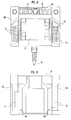
- FIGs. 1A and 1B are front and rear elevational views, respectively, showing a teaching pendant in which an enabling device according to an embodiment of the present invention is used.
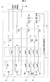
- FIG. 2 is a circuit diagram showing the configuration of the enabling device.
- FIG. 3 is a chart representing open/closed states of contacts of deadman switches included in the enabling device.
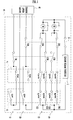
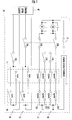
- FIG. 4 is a circuit diagram of the enabling device in a state where the deadman switches are unoperated.
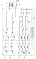
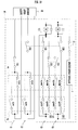
- FIG. 5 is a circuit diagram of the enabling device in a state where a first deadman switch is operated to assume the second position.
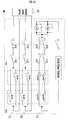
- FIG. 6 is a circuit diagram of the enabling device in a state where the first deadman switch is operated to assume the second position and a second deadman switch operated to assume the third position.
- FIG. 1A and 1B are front and rear elevational views, respectively, showing a teaching pendant in which an enabling device according to an embodiment of the present invention is used.
- FIG. 2 is a circuit diagram showing the configuration of the enabling
- FIG. 7 is a circuit diagram of the enabling device in a state where the first deadman switch is operated to assume the second position and the second deadman switch reset to the first position from the third position.
- FIG. 8 is a circuit diagram of the enabling device in a state where the deadman switches are unoperated, with a first monitor circuit short-circuited.
- FIG. 9 is a circuit diagram of the enabling device in a state where the first deadman switch is operated to assume the second position and the second deadman switch operated to assume the third position, with the first monitor circuit short-circuited.
- FIG. 10 is a circuit diagram of the enabling device in a state where the first deadman switch is operated to assume the second position and the second deadman switch reset to the first position from the third position, with the first monitor circuit short-circuited.
- FIG. 11 is a circuit diagram showing the configuration of an enabling device according to another embodiment of the present invention.
- FIG. 12 is a circuit diagram of a conventional enabling device.
- FIGs. 1A and 1B are front and rear elevational views, respectively, showing a teaching pendant in which an enabling device according to an embodiment of the present invention is used.
- the pendant 10 has a display panel 11, such as an LCD, disposed centrally of the front side of its casing.
- a row of transparent operation keys 12 are arranged on a transparent touch switch on each of opposite lateral sides of the upper surface of the display panel 11. When pressed, each of the operation keys 12 is displaced downwardly to turn ON the touch switch provided on the upper surface of the display panel 11.
- Plural pushbutton switches 13 are arranged above the display panel 11 on the front side of the pendant 10.
- the operation keys 12 and pushbutton switches 13 are each configured to receive an input of an instruction to output an operating signal assigned to a respective one of the keys and switches. Particularly, the operation keys 12 are each assigned the particulars of a switch image on each screen displayed on the display panel 11.
- the display panel 11 may be configured to serve as an operation switch by using a touch panel.
- the casing of the pendant 10 is formed with grips 14a and 14b on right and left lateral sides thereof.
- a non-illustrated subject apparatus to be taught such as an industrial robot
- the operator holds the pendant 10 by his or her both hands from the opposite lateral sides and operates the operation keys 12 or the pushbutton switches 13 by the thumbs.
- the pendant 10 is connected to a control circuit of the subject apparatus via a cable 18 so that an operating signal assigned to the operation key 12 or the pushbutton switch 13 which is operated by the operator is inputted to the control circuit of the subject apparatus.
- the rear side of casing of the pendant 10 is formed with dents 15a and 15b continuously with respective grips 14a and 14b.
- Deadman switches 1a and 1b are disposed on angular portions intermediate the grips 14a and 14b and the dents 15a and 15b.
- the deadman switch 1a is a right-handed deadman switch located at a right-hand operating position where the four fingers, excluding the thumb, of the right hand of the operator gripping the grip 14a situated on the right-hand side as viewed from the front side of the pendant 10 are to be positioned.
- the deadman switch 1b is a left-handed deadman switch located at a left-hand operating position where the four fingers, excluding the thumb, of the left hand of the operator gripping the grip 14b situated on the left-hand side as viewed from the front side of the pendant 10 are to be positioned.
- the deadman switches 1a and 1b are each a three-position switch having main contact positions including a first position assumed in an unoperated condition, a second position assumed in a lightly depressed condition, i.e., in a half-operated condition, and a third position assumed in a strongly depressed condition, i.e., in a completely-operated condition.
- the main contact position shifts from the first position to the third position sequentially. When the operating force is released, each deadman switch is reset to the first position from the third position.
- FIG. 2 is a circuit diagram showing the configuration of the enabling device according to this embodiment of the present invention.
- the enabling device incorporated in the teaching pendant 10 comprises a first enabling signal circuit C1, a second enabling signal circuit C2, a first monitor circuit C3, and a second monitor circuit C4, the circuits C1 to C4 comprising contacts included in the right and left deadman switches 1a and 1b and relays R1 and R2.
- the first and second monitor circuits C3 and C4 are supplied with electric power from an internal power source 2 via a main switch 15.
- the right-handed deadman switch 1a is a three-position deadman switch having six contacts including: normally closed contacts msw1a, msw2a, msw3a, and msw4a which are each configured to become open and closed in accordance with any one of the operated positions, namely, the first position assumed in the unoperated condition, the second position assumed in the half-operated condition and the third position assumed in the completely-operated condition; and two main contacts sw1a and sw2a each configured to assume an OFF-state at the first and third positions and an ON-state at the second position.
- the left-handed deadman switch 1b is a three-position deadman switch having six contacts including: normally closed contacts msw1b, msw2b, msw3b, and msw4b which are each configured to become open and closed in accordance with any one of the operated positions, namely, the first position assumed in the unoperated condition, the second position assumed in the half-operated condition and the third position assumed in the completely operated condition; and two main contacts sw1b and sw2b each configured to assume an OFF-state at the first and third positions and an ON-state at the second position.
- each halftone segment represents the ON-state of a respective one of the contacts.
- the relay R1 has two normally open contacts R11 and R12 and one normally closed contact R13.
- the relay R2 has two normally open contacts R21 and R22 and one normally closed contact R23.
- the first enabling signal circuit C1 is formed by connecting one normally open contact R11 of the relay R1 in series with a parallel circuit in which the main contact sw1a and the main contact sw1b of respective of the right and left deadman switches 1a and 1b are connected in parallel.
- the second enabling signal circuit C2 is formed by connecting the normally open contact R21 of the relay R2 in series with a parallel circuit in which the main contact sw2a and the main contact sw2b of respective of the right and left deadman switches 1a and 1b are connected in parallel.
- the first monitor circuit C3 is formed by connecting the relay R1 in series with a parallel circuit parallel-connecting a first series circuit C31 in which the normally closed contact msw1a included in the deadman switch 1a, the normally closed contact msw1b included in the deadman switch 1b, and the normally closed contact R23 of the other relay R2 are connected in series and a second series circuit C32 in which the normally closed contact msw3a included in the deadman switch 1a, the normally closed contact msw3b included in the deadman switch 1b and the normally open contact R12 of the relay R1 are connected in series.
- the second monitor circuit C4 is formed by connecting the relay R2 in series with a parallel circuit parallel-connecting a third series circuit C41 in which the normally closed contact msw2a included in the deadman switch 1a, the normally closed contact msw2b included in the deadman switch 1b, and the normally closed contact R13 of one relay R1 are connected in series and a fourth series circuit C42 in which the normally closed contact msw4a included in the deadman switch 1a, the normally closed contact msw4b included in the deadman switch 1b, and the normally open contact R22 of the relay R2 are connected in series.
- the relays R1 and R2 correspond to the switching means of the present invention.
- FIG. 4 shows a state where the deadman switches are in the unoperated condition while the main switch of the teaching pendant is ON;
- FIG. 5 shows a state where one deadman switch is operated to assume the second position;
- FIG. 6 shows a state where one deadman switch is kept in the second position and the other deadman switch is operated to assume the third position; and
- FIG. 7 shows a state where one deadman switch is kept in the second position and the other deadman switch is reset to the first position.
- the internal powder source 2 energizes the first series circuit C31 of the first monitor circuit C3 and the third series circuit C41 of the second monitor circuit C4 thereby exciting the relays R1 and R2.
- This causes the normally open contacts R11 and R12 and the normally open contacts R21 and R22 to be turned ON and the normally closed contacts R13 and R23 to be turned OFF in the relays R1 and R2, whereby the enabling signal output lines of respective of the first and second enabling signal circuits C1 and C2 are closed as shown in FIG. 4.
- the relays R1 and R2 are kept energized via the second series circuit C32 of the first monitor circuit C3 and the fourth series circuit C42 of the second monitor circuit C4, respectively, so that the state shown in FIG. 4 is maintained.
- the main contacts sw1a and sw2a are turned ON and the normally closed contacts msw1a and msw2a turned OFF in the deadman switch 1a, as shown in FIG. 5. Since the main contacts sw1a and sw2a of the deadman switch 1a are turned ON, the first and second enabling signal circuits C1 and C2 output an enabling signal to an external safety relay module 20.
- the relays R1 and R2 are kept energized via the second series circuit C32 of the first monitor circuit C3 and the fourth series circuit C42 of the second monitor circuit C4, respectively, so that the state shown in FIG. 5 is maintained.
- teaching to the mechanical apparatus via a non-illustrated controller including the safety relay module 20 becomes possible by means of a teaching signal corresponding to an operation on operation switch 12 or the like included in the teaching pendant 10.
- the enabling device When the right-handed deadman switch 1a also is reset to the first position from the state shown in FIG. 7, the enabling device resumes the state shown in FIG. 4 from the state shown in FIG. 7 through the state in which the main switch 15 is ON.
- the enabling device it becomes possible for the enabling device to output the enabling signal by operating either of the deadman switches 1a and 1b and, hence, teaching to the mechanical apparatus becomes possible.
- the relay R1 is kept excited to keep the normally open contact R11 thereof ON because of the short circuit in the first monitor circuit C3, thus keeping the first enabling signal circuit C1 inputting the enabling signal to the external safety relay module 20.
- the safety relay module 20 enables the teaching signal from the teaching pendant 10 only when both of the first and second enabling signal circuits C1 and C2 input the enabling signal to the safety relay module 20, teaching to the mechanical apparatus becomes impossible from the time the input of the enabling signal from the second enabling signal circuit C2 is stopped, thus causing the mechanical apparatus to stop acting. Therefore, the operator can avoid danger.
- FIGs. 8 to 10 show the case where only the first monitor circuit C3 is short-circuited
- the relay R1 included in the first monitor circuit C3 functions like the relay R2 functioning as shown in FIGs. 8 to 10 if only the second monitor circuit C4 is short-circuited.
- the enabling signal output line of the first enabling signal circuit C1 is opened.
- the teaching pendant enabling device is capable of accurately detecting a single failure while preventing its safety function from being impaired by a single short-circuit failure.
- FIG. 11 is a circuit diagram showing the configuration of an enabling device according to another embodiment of the present invention.
- the enabling device 10' according to this embodiment is applied to a teaching pendant having three three-position switches 1a to 1c, each of which has three main contacts and two sets of three normally closed contacts.
- switch 1a has three main switches sw1a to sw3a and two sets of three normally closed contacts msw1a to msw6a (including a set of normally closed contacts msw1a to msw3a and a set of normally closed contacts msw4a to msw6a);
- switch 1b has three main switches sw1b to sw3b and two sets of three normally closed contacts msw1b to msw6b (including a set of normally closed contacts msw1b to msw3b and a set of normally closed contacts msw4b to msw6b);
- switch 1c has three main switches sw1c to sw3c and two sets of three normally closed contacts msw1c to msw6c (including a set of normally closed contacts msw1c to msw3c and a set of normally closed contacts msw4c to msw6c.)
- the enabling device 10' has three enabling signal circuits and three monitor circuits formed therein. By thus adding a contact and a relay to each three-position switch to form three or more monitor circuits, the enabling device 10' is capable of accurate detection of occurrences of plural duplicated failures.
- the number of enabling signal circuits and the number of monitor circuits need not necessarily be equal to each other. For example, it is possible to form two enabling signal circuits and four monitor circuits and then connect the output line of each of the two enabling signal circuits in series with two contacts of each of the relays included in two different monitor circuits. Also, the number of three-position switches provided on the teaching pendant need not necessarily be three as long as the number is plural.
- the present invention can also be embodied into an enabling device applicable to a teaching pendant provided with plural three-position switches each having two sets of three or more (2+n) normally closed contacts (wherein n is an integer of not less than 1), the enabling device having m enabling signal circuits (wherein m is an integer of not less than two) and three or more (2+n) monitor circuits wherein n is an integer of not less than 1.)
- the relay included in at least one monitor circuit opens the output line of at least one enabling signal circuit.
- each relay has m+1 normally open contacts
- one normally open contact of each relay may be connected in series with a respective one of the enabling signal circuits.
Landscapes
- Engineering & Computer Science (AREA)
- Robotics (AREA)
- Mechanical Engineering (AREA)
- Manipulator (AREA)
- Numerical Control (AREA)
Abstract
Description
first to fourth normally closed contacts each configured to become open or closed in accordance with any one of operated positions including a first position assumed in an unoperated condition, a second position assumed in a half-operated condition, and a third position assumed in a completely operated condition; and
first and second main contacts each configured to assume an OFF-state at the first and third positions and an ON-state at the second position,
wherein the second deadman switch has:
fifth to eighth normally closed contacts each configured to become open or closed in accordance with any one of operated positions including a first position assumed in an unoperated condition, a second position assumed in a half-operated condition, and a third position assumed in a completely operated condition; and
third and fourth main contacts each configured to assume an OFF-state at the first and third positions and an ON-state at the second position,
wherein the two switching means are first and second relays, the first relay having first and second normally open contacts and a ninth normally closed contact; and the second relay having third and fourth normally open contacts and a tenth normally closed contact,
wherein the first enabling signal circuit includes the first normally open contact connected in series with a parallel circuit parallel-connecting the first and third main contacts; and the second enabling signal circuit includes the third normally open contact connected in series with a parallel circuit parallel-connecting the second and fourth main contacts, and
wherein the first monitor circuit connects the first relay in series with a parallel circuit parallel-connecting a first series circuit in which the first, fifth, and tenth normally closed contacts are connected in series and a second series circuit in which the third and seventh normally closed contacts and the second normally open contact are connected in series; and the second monitor circuit connects the second relay in series with a parallel circuit parallel-connecting a third series circuit in which the second, sixth, and ninth normally closed contacts are connected in series and a fourth series circuit in which the fourth and eighth normally closed contacts and the fourth normally open contact are connected in series. In this arrangement, when excited, the relays included in the two monitor circuits closes respective of the output lines of the two enabling signal circuits. The relay included in the monitor circuit in a state shut down by turning one of the deadman switches into the second OFF-state is not energized unless the remaining monitor circuit is shut down. Accordingly, when the remaining monitor circuit is short-circuited, the relay included therein is kept excited continuously and, hence, the output line of one of the two enabling signal circuit is kept closed continuously. However, the relay included in the remaining monitor circuit keeps open the output line of the other enabling signal circuit. Accordingly, it is not possible that the enabling signal is outputted from both of the two output lines.
Claims (3)
- A teaching pendant enabling device including first and second enabling signal circuits each configured to selectively output an enabling signal for enabling a teaching signal given to a mechanical apparatus in accordance with operated states of first and second deadman switches each configured to assume a first OFF-state when unoperated, an ON-state when half-operated, and a second OFF-state when completely operated, comprising:wherein, after an operating member of at least one of the first and second deadman switches has been turned into the second OFF-state, each of the first and second monitor circuits causes the respective one of the two switching means to keep the output line in an open state until both of the first and second deadman switches each made to assume the first OFF-state are detected.two switching means configured to open/close an enabling signal output line of a respective one of the first and second enabling signal circuits; andfirst and second monitor circuits each configured to actuate a respective one of the two switching means in accordance with results of detection of the operated states of the first and second deadman switches,
- The teaching pendant enabling device according to claim 1,
wherein the first deadman switch has:wherein the second deadman switch has:first to fourth normally closed contacts each configured to become open or closed in accordance with any one of operated positions including a first position assumed in an unoperated condition, a second position assumed in a half-operated condition, and a third position assumed in a completely operated condition; andfirst and second main contacts each configured to assume an OFF-state at the first and third positions and an ON-state at the second position,wherein the two switching means are first and second relays, the first relay having first and second normally open contacts and a ninth normally closed contact; and the second relay having third and fourth normally open contacts and a tenth normally closed contact,fifth to eighth normally closed contacts each configured to become open or closed in accordance with any one of operated positions including a first position assumed in an unoperated condition, a second position assumed in a half-operated condition, and a third position assumed in a completely operated condition; andthird and fourth main contacts each configured to assume an OFF-state at the first and third positions and an ON-state at the second position,
wherein the first enabling signal circuit includes the first normally open contact connected in series with a parallel circuit parallel-connecting the first and third main contacts; and the second enabling signal circuit includes the third normally open contact connected in series with a parallel circuit parallel-connecting the second and fourth main contacts, and
wherein the first monitor circuit connects the first relay in series with a parallel circuit parallel-connecting a first series circuit in which the first, fifth, and tenth normally closed contacts are connected in series and a second series circuit in which the third and seventh normally closed contacts and the second normally open contact are connected in series; and the second monitor circuit connects the second relay in series with a parallel circuit parallel-connecting a third series circuit in which the second, sixth, and ninth normally closed contacts are connected in series and a fourth series circuit in which the fourth and eighth normally closed contacts and the fourth normally open contact are connected in series. - A teaching pendant enabling device including plural enabling signal circuits each configured to selectively output an enabling signal for enabling a teaching signal given to a mechanical apparatus in accordance with operated states of plural deadman switches each configured to assume a first OFF-state when unoperated, an ON-state when half-operated, and a second OFF-state when completely operated, comprising:wherein, after an operating member of at least one of the deadman switches has been turned into the second OFF-state, each of the three or more monitor circuits causes the respective one of the switching means to keep the output line in an open state until all of the plural deadman switches each made to assume the first OFF-state are detected.three or more switching means each configured to open/close an enabling signal output line of a respective one of the plural enabling signal circuits; andthree or more monitor circuits each configured to actuate a respective one of the three or more switching means in accordance with results of detection of the operated states of the plural deadman switches,
Applications Claiming Priority (3)
| Application Number | Priority Date | Filing Date | Title |
|---|---|---|---|
| JP2002380746 | 2002-12-27 | ||
| JP2002380746A JP4314027B2 (en) | 2002-12-27 | 2002-12-27 | Teaching pendant enable device |
| PCT/JP2003/016433 WO2004060618A1 (en) | 2002-12-27 | 2003-12-22 | Enabling unit of teaching pendant |
Publications (3)
| Publication Number | Publication Date |
|---|---|
| EP1595659A1 true EP1595659A1 (en) | 2005-11-16 |
| EP1595659A4 EP1595659A4 (en) | 2010-05-12 |
| EP1595659B1 EP1595659B1 (en) | 2011-03-16 |
Family
ID=32708450
Family Applications (1)
| Application Number | Title | Priority Date | Filing Date |
|---|---|---|---|
| EP03782866A Expired - Lifetime EP1595659B1 (en) | 2002-12-27 | 2003-12-22 | Enabling unit of teaching pendant |
Country Status (5)
| Country | Link |
|---|---|
| US (1) | US20060212167A1 (en) |
| EP (1) | EP1595659B1 (en) |
| JP (1) | JP4314027B2 (en) |
| DE (1) | DE60336430D1 (en) |
| WO (1) | WO2004060618A1 (en) |
Cited By (2)
| Publication number | Priority date | Publication date | Assignee | Title |
|---|---|---|---|---|
| US9079317B2 (en) | 2008-07-21 | 2015-07-14 | Keba Ag | Method of operating a mobile hand-operated device for outputting or enabling potentially dangerous control commands and corresponding hand-operated device |
| CN112631256A (en) * | 2020-12-29 | 2021-04-09 | 浙江中控技术股份有限公司 | Switching value output module with safe function and diagnosis processing method |
Families Citing this family (4)
| Publication number | Priority date | Publication date | Assignee | Title |
|---|---|---|---|---|
| JP3951131B2 (en) * | 2003-06-09 | 2007-08-01 | 株式会社安川電機 | Teach pendant control method and apparatus |
| JP1606242S (en) * | 2017-11-22 | 2018-06-11 | ||
| CN117222501B (en) * | 2021-06-03 | 2026-05-19 | 松下知识产权经营株式会社 | Enable switching device and load drive control device having the same. |
| WO2024102726A1 (en) * | 2022-11-07 | 2024-05-16 | Noland Samantha | Systems and methods to configure a robotic welding system |
Family Cites Families (5)
| Publication number | Priority date | Publication date | Assignee | Title |
|---|---|---|---|---|
| JP4014662B2 (en) * | 1995-09-18 | 2007-11-28 | ファナック株式会社 | Robot teaching operation panel |
| JP3212546B2 (en) * | 1997-08-25 | 2001-09-25 | ファナック株式会社 | Deadman switch mechanism for robot emergency stop and teaching operation panel |
| JPH1177579A (en) * | 1997-09-03 | 1999-03-23 | Fanuc Ltd | Robot emergency stop switch mechanism and teaching operation panel provided with the mechanism |
| JP3566639B2 (en) * | 2000-09-06 | 2004-09-15 | 和泉電気株式会社 | Teaching pendant enable device |
| JP2002334625A (en) * | 2001-05-09 | 2002-11-22 | Yaskawa Electric Corp | 3 position deadman switch |
-
2002
- 2002-12-27 JP JP2002380746A patent/JP4314027B2/en not_active Expired - Fee Related
-
2003
- 2003-12-22 EP EP03782866A patent/EP1595659B1/en not_active Expired - Lifetime
- 2003-12-22 DE DE60336430T patent/DE60336430D1/en not_active Expired - Lifetime
- 2003-12-22 WO PCT/JP2003/016433 patent/WO2004060618A1/en not_active Ceased
- 2003-12-22 US US10/540,455 patent/US20060212167A1/en not_active Abandoned
Cited By (3)
| Publication number | Priority date | Publication date | Assignee | Title |
|---|---|---|---|---|
| US9079317B2 (en) | 2008-07-21 | 2015-07-14 | Keba Ag | Method of operating a mobile hand-operated device for outputting or enabling potentially dangerous control commands and corresponding hand-operated device |
| CN112631256A (en) * | 2020-12-29 | 2021-04-09 | 浙江中控技术股份有限公司 | Switching value output module with safe function and diagnosis processing method |
| CN112631256B (en) * | 2020-12-29 | 2022-03-18 | 浙江中控技术股份有限公司 | A functionally safe switching quantity output module and diagnostic processing method |
Also Published As
| Publication number | Publication date |
|---|---|
| DE60336430D1 (en) | 2011-04-28 |
| JP2004209579A (en) | 2004-07-29 |
| EP1595659A4 (en) | 2010-05-12 |
| EP1595659B1 (en) | 2011-03-16 |
| WO2004060618A1 (en) | 2004-07-22 |
| US20060212167A1 (en) | 2006-09-21 |
| JP4314027B2 (en) | 2009-08-12 |
Similar Documents
| Publication | Publication Date | Title |
|---|---|---|
| EP0857548B1 (en) | Safety device for robot | |
| US10478965B2 (en) | Robot system | |
| US7501778B2 (en) | Robot control device | |
| US6160324A (en) | Deadman switch mechanism for emergency stop of robot and teaching operation | |
| US6051894A (en) | Safety device of industrial robot | |
| EP1595659B1 (en) | Enabling unit of teaching pendant | |
| US7154197B2 (en) | Control apparatus and control method for the same | |
| US20050209734A1 (en) | Robot system and controller | |
| US7019227B2 (en) | Enabler of teaching pendant | |
| US7337014B2 (en) | Teach pendant control method and device | |
| JP4242697B2 (en) | Operation board | |
| JP4064865B2 (en) | Teaching pendant safety device | |
| JP2716684B2 (en) | Multifunctional panel used for robots | |
| JPH06278069A (en) | Robot control panel | |
| EP0303708B1 (en) | Teaching instruction panel for industrial robots | |
| KR100479958B1 (en) | Touch screen controller for gas cabinet apparatus | |
| JPS61177501A (en) | Switching circuit | |
| JP4416570B2 (en) | Safety switch device | |
| US20250153359A1 (en) | Robot control device and robot system | |
| JPS5937093A (en) | Drive safety circuit for industrial robot | |
| JP3775504B2 (en) | Teach pendant controller | |
| CN121586635A (en) | Robot system | |
| JP2025142830A (en) | Robot operating device | |
| JP2519799B2 (en) | Power supply | |
| JPH1049222A (en) | Operation device |
Legal Events
| Date | Code | Title | Description |
|---|---|---|---|
| PUAI | Public reference made under article 153(3) epc to a published international application that has entered the european phase |
Free format text: ORIGINAL CODE: 0009012 |
|
| 17P | Request for examination filed |
Effective date: 20050725 |
|
| AK | Designated contracting states |
Kind code of ref document: A1 Designated state(s): AT BE BG CH CY CZ DE DK EE ES FI FR GB GR HU IE IT LI LU MC NL PT RO SE SI SK TR |
|
| AX | Request for extension of the european patent |
Extension state: AL LT LV MK |
|
| DAX | Request for extension of the european patent (deleted) | ||
| RBV | Designated contracting states (corrected) |
Designated state(s): DE FR GB |
|
| A4 | Supplementary search report drawn up and despatched |
Effective date: 20100412 |
|
| GRAP | Despatch of communication of intention to grant a patent |
Free format text: ORIGINAL CODE: EPIDOSNIGR1 |
|
| RIC1 | Information provided on ipc code assigned before grant |
Ipc: B25J 9/22 20060101ALI20100902BHEP Ipc: B25J 19/06 20060101AFI20100902BHEP |
|
| GRAS | Grant fee paid |
Free format text: ORIGINAL CODE: EPIDOSNIGR3 |
|
| GRAA | (expected) grant |
Free format text: ORIGINAL CODE: 0009210 |
|
| AK | Designated contracting states |
Kind code of ref document: B1 Designated state(s): DE FR GB |
|
| REG | Reference to a national code |
Ref country code: GB Ref legal event code: FG4D |
|
| REF | Corresponds to: |
Ref document number: 60336430 Country of ref document: DE Date of ref document: 20110428 Kind code of ref document: P |
|
| REG | Reference to a national code |
Ref country code: DE Ref legal event code: R096 Ref document number: 60336430 Country of ref document: DE Effective date: 20110428 |
|
| PLBE | No opposition filed within time limit |
Free format text: ORIGINAL CODE: 0009261 |
|
| STAA | Information on the status of an ep patent application or granted ep patent |
Free format text: STATUS: NO OPPOSITION FILED WITHIN TIME LIMIT |
|
| 26N | No opposition filed |
Effective date: 20111219 |
|
| REG | Reference to a national code |
Ref country code: DE Ref legal event code: R097 Ref document number: 60336430 Country of ref document: DE Effective date: 20111219 |
|
| REG | Reference to a national code |
Ref country code: FR Ref legal event code: PLFP Year of fee payment: 13 |
|
| REG | Reference to a national code |
Ref country code: FR Ref legal event code: PLFP Year of fee payment: 14 |
|
| REG | Reference to a national code |
Ref country code: FR Ref legal event code: PLFP Year of fee payment: 15 |
|
| PGFP | Annual fee paid to national office [announced via postgrant information from national office to epo] |
Ref country code: FR Payment date: 20221020 Year of fee payment: 20 |
|
| PGFP | Annual fee paid to national office [announced via postgrant information from national office to epo] |
Ref country code: GB Payment date: 20221020 Year of fee payment: 20 Ref country code: DE Payment date: 20221020 Year of fee payment: 20 |
|
| REG | Reference to a national code |
Ref country code: DE Ref legal event code: R071 Ref document number: 60336430 Country of ref document: DE |
|
| REG | Reference to a national code |
Ref country code: GB Ref legal event code: PE20 Expiry date: 20231221 |
|
| PG25 | Lapsed in a contracting state [announced via postgrant information from national office to epo] |
Ref country code: GB Free format text: LAPSE BECAUSE OF EXPIRATION OF PROTECTION Effective date: 20231221 |
|
| PG25 | Lapsed in a contracting state [announced via postgrant information from national office to epo] |
Ref country code: GB Free format text: LAPSE BECAUSE OF EXPIRATION OF PROTECTION Effective date: 20231221 |