EP1595635A1 - Arc stud welding device and method for securely welding a stud to a deformable component - Google Patents
Arc stud welding device and method for securely welding a stud to a deformable component Download PDFInfo
- Publication number
- EP1595635A1 EP1595635A1 EP05010038A EP05010038A EP1595635A1 EP 1595635 A1 EP1595635 A1 EP 1595635A1 EP 05010038 A EP05010038 A EP 05010038A EP 05010038 A EP05010038 A EP 05010038A EP 1595635 A1 EP1595635 A1 EP 1595635A1
- Authority
- EP
- European Patent Office
- Prior art keywords
- component
- welding
- stud
- depth
- head
- Prior art date
- Legal status (The legal status is an assumption and is not a legal conclusion. Google has not performed a legal analysis and makes no representation as to the accuracy of the status listed.)
- Withdrawn
Links
- 238000003466 welding Methods 0.000 title claims abstract description 131
- 238000000034 method Methods 0.000 title claims abstract description 12
- 238000002844 melting Methods 0.000 claims abstract description 16
- 230000008018 melting Effects 0.000 claims abstract description 16
- 238000010891 electric arc Methods 0.000 claims description 9
- 238000003825 pressing Methods 0.000 claims description 5
- 230000000994 depressogenic effect Effects 0.000 abstract description 4
- 238000001514 detection method Methods 0.000 description 6
- 230000002950 deficient Effects 0.000 description 4
- 238000010586 diagram Methods 0.000 description 2
- 230000003287 optical effect Effects 0.000 description 2
- 230000002411 adverse Effects 0.000 description 1
- 230000000694 effects Effects 0.000 description 1
- 238000005259 measurement Methods 0.000 description 1
- 239000002184 metal Substances 0.000 description 1
- 238000000926 separation method Methods 0.000 description 1
Images

Classifications
-
- B—PERFORMING OPERATIONS; TRANSPORTING
- B23—MACHINE TOOLS; METAL-WORKING NOT OTHERWISE PROVIDED FOR
- B23K—SOLDERING OR UNSOLDERING; WELDING; CLADDING OR PLATING BY SOLDERING OR WELDING; CUTTING BY APPLYING HEAT LOCALLY, e.g. FLAME CUTTING; WORKING BY LASER BEAM
- B23K9/00—Arc welding or cutting
- B23K9/20—Stud welding
-
- B—PERFORMING OPERATIONS; TRANSPORTING
- B23—MACHINE TOOLS; METAL-WORKING NOT OTHERWISE PROVIDED FOR
- B23K—SOLDERING OR UNSOLDERING; WELDING; CLADDING OR PLATING BY SOLDERING OR WELDING; CUTTING BY APPLYING HEAT LOCALLY, e.g. FLAME CUTTING; WORKING BY LASER BEAM
- B23K9/00—Arc welding or cutting
- B23K9/20—Stud welding
- B23K9/205—Means for determining, controlling or regulating the arc interval
Definitions
- the present invention relates to an arc stud welding device and method using an arc discharge in which electric power is applied between a welding component such as a stud, nut or tube, and a welded component, such as a car body or metal panel, in order to generate an arc, melt the welding component and a portion of the welded component, and weld the welding component to the welded component.
- a welding component such as a stud, nut or tube
- a welded component such as a car body or metal panel
- So-called drawn arc stud welding is well known.
- electric power is applied between a welding component such as a stud and a welded component such as a car body, a low current pilot arc followed by a high current main arc are generated between the welding component and welded component separated from one another, and the welding component is welded to the welded component.
- Patent Document 1 One type of arc stud welding device is disclosed in Unexamined Patent Application Publication (Kokai) No. 07-009146 (Patent Document 1).
- a linear motor is used in the welding tool, the configuration of the welding tool holding the stud is simplified, and the positioning of the stud over the welded component is made easier.
- the linear motor is operated so as to raise the welding component from a reference plane of the welded component to a pre-determined height, an arc is generated between the components, and the melted tip of the welding component is pressed into the melted portion of the welded component to a predetermined sink-in depth.
- Unexamined Patent Application Publication (Kokai) No. 07-136766 Patent Document 2
- a circuit is installed to detect contact between a stud and a welded component, and the contact between the stud and the welded component is monitored to ensure the start of welding.
- Unexamined Patent Application Publication (Kokai) No. 11-077310 Patent Document 3
- the lift-up distance for a stud with respect to a welded component and the push-in depth for the stud with respect to the welded component after the lift up are preset, the lift-up distance and push-in depth are monitored to determine whether or not they are within the tolerances for preset values, and the pass or fail quality of the welding is checked.
- Patent Document 4 a stud welding device is disclosed that is able to weld a stud to various types of welded components with different shapes. Correction control is performed by feed-back of the amount of movement to position the stud in the welding tool over a predetermined position on the welded component.
- the welding component is pressed into a portion of the welded component, and electric power is applied to the welding component and the welded component in contact with one another.
- a linear motor is operated to lift the welding component from the welded component, an arc is generated, and a tip of the welding component and the welded portion of the welded component are melted.
- the welding component is then pressed into the welded component, and the welding component is welded to the welded component.
- the welding component Since the welding component is forcibly brought into contact with the welded component at the start of the welding operation, if the welded component is not sufficiently rigid, the pressure applied to the welded component may cause it to become bowed or bent, forming a depression, and cause the welded component to sink to a sink-in depth below its original welded plane.
- Patent Documents 1 through 4 do not meaningfully address this problem.
- a tube-shaped component called a flash shield may be placed around the head on the welding tool in an effort to hold the lift-up distance and the sink-in distance constant. Space is needed for a flash shield of fixed size to make contact with the portion of the welded component to be welded, but proper welding cannot be performed if the location or shape of that portion of the welded component does not provide enough space to accommodate the flash shield.
- An object of the present invention is to provide an arc stud welding device and method in which a welding component (first component) is lifted by an appropriate amount to permit generation of a proper arc, even if the welded component (second component) has been forcibly depressed by the welding component to a sink-in depth before melting, and in which the welding component is lowered by an appropriate amount and a push-in depth is reached after melting.
- the present invention provides an improved stud welding device and method for welding a welding component, such as a stud, to a welded component, such as a panel, using an arc discharge.
- the welding device includes a welding tool with a head for holding a welding component.
- the welding tool comprises a linear motor for lowering the welding component and pressing the welding component against the welded component and for raising the welding component from the welded component.
- a position sensor detects the position of the welding component relative to the welded component, and a contact detector detects contacting of the welding component with the welded component.
- the welding tool is connected to a power supply for supplying electric power.
- a controller controls the power supply and the linear motor.
- the controller supplies electric power to both components after contact between the welding component and the welded component is detected and maintains the supply of power so that an arc is generated between the components when the linear motor lifts the welding component to a predetermined lift-up height from a reference plane of the welded component, to melt a tip of the welding component and a portion of the welded component
- the linear motor is then operated to lower the welding component and push the melted tip of the welding component into the melted portion of the welded component until a predetermined push-in depth is reached, so as to establish secure contact between the welding component and the welded component and weld them together.
- the welded component is not sufficiently rigid, and the welded component sinks below its original plane to a sink-in depth when the welding component is pressed into the welded component before being lifted, the sink-in depth is measured, based on signals from the contact detector and signals from the position sensor, in order to lift the welding component by an amount corresponding approximately to the sum of the sink-in depth and the predetermined lift-up height.
- the linear motor is operated to press the welding component against the welded component with a downward stroke corresponding approximately to the sum of the lift-up height, the sink-in depth, and the push-in depth.
- the welding component can be lifted to the proper height for arc welding, and the welding component can be pressed into the welded component to the proper depth after melting. A flash shield is not required, and defective welding is minimized.
- the controller is preferably configured to operate the linear motor so as to push the melted welding component into the melted portion of the welded component using a pressure application identical to the first pressure application when the welding component was first brought into contact with the welded component before melting. This promotes proper push-in depth. Also, the sink-in depth is preferably determined using the original reference plane for the welded component
- the controller preferably includes a system control unit and a linear motor control unit, and the linear motor control unit is preferably housed inside the welding tool or a welding component supply device arranged adjacent to the welding tool. Operation of the welding tool head holding the welding component is performed using feedback control, and the controller is positioned near the welding tool.
- the control circuit is simple and does not take up much space.
- the arc stud welding device 1 of the present invention comprises a welding tool 2 and a controller 3 accommodated in a housing separate from the welding tool 2.
- the controller 3 can also be accommodated in the same housing as the welding tool 2 to create an integrated arc stud welding device 1.
- the welding tool 2 can be operated using a manipulator such as a robotic arm.
- the arc stud welding device 1 welds a stud 5 serving as the welding component to a car body 7 serving as the welded component, at a predetermined position.
- the welding component is a stud 5, it could be a nut, bolt or tube, for example.
- the welded component could be any appropriate panel or base.
- the welding tool 2 has a head 6 at the tip for holding the stud 5, and a linear motor 9 moving axially for bringing the stud 5 held by the head 6 into contact with the welded component 7 and then separating them.
- the welding tool 2 also has a position sensor 10 for detecting the position of the stud 5 relative to the welded component 7, or the distance between the stud 5 and the welded component 7, and outputs position signals to the controller 3.
- the position sensor 10 can take any appropriate form as long as it detects the position of the stud 5 relative to the welded component 7 and outputs position signals.
- the position sensor 10 can be fixed to the head 6 holding the stud 5 and moved by the linear motor 9, using a scale consisting of holes formed at predetermined intervals along the axis of movement.
- a light emitting element (LED) and a light receiving element can be fixed to the housing of the welding tool 2 and arranged to emit and receive a light beam interrupted by the scale. As the scale moves relative to the light beam, a pulse signal is outputted each time a light pulse is received by the light receiving element through one of the holes.
- an optical position encoder can be used if patterns with different shapes are formed for the contact holes corresponding to their height. In this case, the output from the position sensor is a code signal corresponding to the position. When an optical position sensor is used, the adverse effect of noise caused by the welding current can be reduced.
- a welding power source 11 is disposed in the controller 3 to generate an arc discharge between the stud 5 held by the head 6 in the welding tool 2 and the welded component 7.
- a system control unit 13 is also disposed in the controller 3.
- the system control unit 13 controls the series of welding operations performed to weld the stud 5 to the welded component 7, in which the stud 5 is pressed down onto the welded component 7 to establish contact therewith, power is applied from the welding power supply 11 to the welded component and the stud, the linear motor 9 is operated to lift the stud from the welded component, a pilot arc is generated, the stud is lifted more and a large current main arc is generated, the stud tip and a portion of the welded component are melted, and the linear motor is operated after melting to press the stud into the melted portion of the welded component and weld them together.
- the system control unit 13 preferably comprises a calculation processor such as a microprocessor, RAM and ROM for storing programs and data, a memory device such as a hard drive, a user interface such as a keyboard and a monitor display, and other devices to perform operations according to a predetermined program.
- a calculation processor such as a microprocessor, RAM and ROM for storing programs and data
- a memory device such as a hard drive
- a user interface such as a keyboard and a monitor display
- other devices to perform operations according to a predetermined program.
- a linear motor operation control unit 14 is also disposed in the controller 3 to send control signals from the system control unit 13 to the linear motor 9 in the stud welding tool 2 as operation signals.
- position signals are inputted from the position sensor 10 in the welding tool 2, and the position signals are used to perform feedback control when command signals are received from the system control unit 13 and operate the linear motor 9 with great precision.
- the linear motor operation control unit 14 shown in the drawing is housed inside a box in the controller 3. However, it can be housed inside the welding tool 2 or inside the stud supplying device (not shown) for automatically supplying studs 5 to the head 6.
- the linear motor operation control unit 14 When the linear motor operation control unit 14 is housed inside the welding tool 2 or inside the stud supplying device, it is preferably positioned near the linear motor 9 to be controlled. This is convenient when performing feedback control of the movement of the linear motor 9. It also allows for a simple control circuit configuration and takes up less space.
- An SOW (stud on workpiece) detection circuit 15 is disposed in the controller 3 as a contact detector for detecting contact of the stud 5 with the welded component 7. This circuit is connected to the head 6 of the welding tool 2.
- the SOW detection circuit 15 detects when the stud 5 makes contact with the welded component 7 at the beginning of the welding operation. For example, it can detect the electric current flowing between the welded component 7 and the head 6 holding the stud 5 so as to detect when the stud 5 makes contact with the welded component 7.
- voltage is supplied from the welding power supply 11 between the stud 5 and the welded component 7 when the stud 5 is apart from the welded component 7.
- the signals from the SOW detection circuit 15 are sent to both the system control unit 13 and the linear motor operation control unit 14.
- the signals from the SOW detection circuit 15 can be used to detect separation between the stud 5 and the welded component 7 as well as contact between the stud 5 and welded component 7.
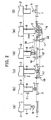
- the linear motor 9 in the welding tool 2 is operated and, as shown in FIG 2 (b), the head 6 is lowered, and the stud 5 is forcibly pressed against the welded component 7 under the first pressure application F1, so that the stud 5 comes into secure contact with the welded component 7.
- This contact is detected by the SOW detection circuit 15. If the welded component 7 is sufficiently rigid, the welded component 7 does not become bowed or bent when the stud 5 is pressed against it under first pressure application F1. However, if the welded component 7 is not sufficiently rigid, the welded component 7 becomes bowed or bent as shown in FIG 2 (c), and the portion to be welded sinks to a sink-in depth 17. The vertical position of the portion of the welded component 7 sunk in to the sink-in depth 17 is then the reference position 18 for the head 6 of the welding tool 2.
- a method used to measure the sink-in depth 17 is to lower the head 6, bring the stud 5 into contact with the welded component 7 under first application pressure F1, and then use the SOW detection circuit 15 to detect the position signal from the position sensor 10 the instant the stud 5 is determined to have come into contact with the welded component 7 and the position signal from the position sensor 10 when the welded portion of the welded component 7 has sunk in and stopped.
- First pressure application F1 is the same as pressure application F(p) (see FIG 2 (e)) when the stud 5 is pressed against the welded component 7 after melting.
- the timing for the sink-in depth 17 measurement is begun when the stud 5 comes into contact with the welded component 7.
- the various welding positions can be measured in preliminary tests before implementing a desired welding operation, so the sink-in depth 17 can be measured and stored beforehand in the system control unit 13.
- the system control unit 13 supplies low voltage from the welding power source 11 to the stud 5 and the welded component 7.
- the linear motor 9 continues to lift the stud until a position signal is received by the linear motor operation control unit 14 from the position sensor 10 indicating that the stud has been lifted by an amount corresponding approximately to the sum of the sink-in depth 17 and the predetermined lift-up height 19.
- the stud 5 is lifted by the linear motor 9 to the predetermined lift-up height 19 above the rebounded welded component 7, as shown in FIG 2(d).
- a pilot arc is generated when the stud 5 is lifted up.
- the system controller 13 then increases the power from the welding power supply 11 and generates a main arc between the stud 5 and the welded component 7, as shown in FIG 2 (d).
- the pilot are and then the main arc are formed properly between the stud 5 and the welded component 7 at the lift-up height 19. Thus, defective welding due to insufficient lifting of the stud does not occur.
- the main arc is generated continuously for a fixed period of time until the flange-shaped portion of the stud 5 and a predetermined portion of the welded component 7 have been melted.
- the system control unit 13 then outputs a signal to the linear motor 9 via the linear motor operation control unit 14 to lower the stud 5.
- the melted portion of the stud 5 is lowered into the melted portion of the welded component 7, and the stud 5 is pushed (or “plunged") into the welded component 7 under pressure application F (p) to weld the components. Because both the tip of the stud 5 and the welded portion of the welded component 7 have both been melted at the time of the plunge, strong and reliable welding is obtained.
- the stud would be pushed in only to a predetermined push-in depth from an original reference plane.
- proper welding is obtained even when the welded component 7 has previously sunk in as shown in FIG 2 (c).
- the linear motor 9 is controlled to move downward by an amount corresponding approximately to the sum of the sink-in depth 17, the lift-up height 19, and a predetermined push-in depth 22.
- the total depression of the welded component 7, after melting is greater than that shown in FIG 2(c) prior to melting.
Landscapes
- Engineering & Computer Science (AREA)
- Physics & Mathematics (AREA)
- Plasma & Fusion (AREA)
- Mechanical Engineering (AREA)
- Butt Welding And Welding Of Specific Article (AREA)
- Arc Welding Control (AREA)
Abstract
The present application presents an arc stud welding device (1) and method, wherein after initial contact of a stud (5) with a
component (7) to which it is to be welded, the stud (5) is lifted by an
amount that permits a proper arc to be formed, even if the component (7) was
depressed by the initial contact with the stud (5). After melting of the tip of the stud (5)
and a portion of the welded component (7), the stud (5) is pressed securely into the
component (7) to weld the stud (5) to the component (7), with the
component (7) being depressed by the stud (5) to an extent greater than that caused by the
initial contact.
Description
The present invention relates to an arc stud welding device and method using an
arc discharge in which electric power is applied between a welding component such as a
stud, nut or tube, and a welded component, such as a car body or metal panel, in order to
generate an arc, melt the welding component and a portion of the welded component, and
weld the welding component to the welded component.
So-called drawn arc stud welding is well known. In this type of arc discharge stud
welding, electric power is applied between a welding component such as a stud and a
welded component such as a car body, a low current pilot arc followed by a high current
main arc are generated between the welding component and welded component separated
from one another, and the welding component is welded to the welded component.
One type of arc stud welding device is disclosed in Unexamined Patent
Application Publication (Kokai) No. 07-009146 (Patent Document 1). In the device
described in Patent Document 1, a linear motor is used in the welding tool, the
configuration of the welding tool holding the stud is simplified, and the positioning of the
stud over the welded component is made easier. As described in Paragraphs 0025 and
0026 of Patent Document 1, the linear motor is operated so as to raise the welding
component from a reference plane of the welded component to a pre-determined height,
an arc is generated between the components, and the melted tip of the welding component
is pressed into the melted portion of the welded component to a predetermined sink-in
depth.
In Unexamined Patent Application Publication (Kokai) No. 07-136766 (Patent
Document 2), a circuit is installed to detect contact between a stud and a welded
component, and the contact between the stud and the welded component is monitored to
ensure the start of welding. In Unexamined Patent Application Publication (Kokai) No.
11-077310 (Patent Document 3), the lift-up distance for a stud with respect to a welded
component and the push-in depth for the stud with respect to the welded component after
the lift up, are preset, the lift-up distance and push-in depth are monitored to determine
whether or not they are within the tolerances for preset values, and the pass or fail quality
of the welding is checked. In Unexamined Patent Application Publication (Kokai) No.
05-000376 (Patent Document 4), a stud welding device is disclosed that is able to weld a
stud to various types of welded components with different shapes. Correction control is
performed by feed-back of the amount of movement to position the stud in the welding
tool over a predetermined position on the welded component.
Generally, in arc stud welding, the welding component is pressed into a portion of
the welded component, and electric power is applied to the welding component and the
welded component in contact with one another. A linear motor is operated to lift the
welding component from the welded component, an arc is generated, and a tip of the
welding component and the welded portion of the welded component are melted. The
welding component is then pressed into the welded component, and the welding
component is welded to the welded component. Since the welding component is forcibly
brought into contact with the welded component at the start of the welding operation, if
the welded component is not sufficiently rigid, the pressure applied to the welded
component may cause it to become bowed or bent, forming a depression, and cause the
welded component to sink to a sink-in depth below its original welded plane.
When the welding component is lifted for generating the arc, the welding
component is usually lifted to a predetermined height above the position where the
welding component came into contact with the welded component. However, if the
applied pressure has caused the welded component to become bowed or bent, it may
return to its original plane when it is no longer under pressure. Lifting of the welding
component to the predetermined height from the bowed or bent position may not be
sufficient to permit generating a proper arc, which may cause defective welding. When
the sink-in depth is greater than the predetermined lift-up height, the rebound of the
welded component causes the welding component to remain in contact therewith even
after the welding component has been lifted. Thus, an arc cannot be generated. Patent
Documents 1 through 4 do not meaningfully address this problem.
Also, when the welded component is not sufficiently rigid and sinks below its
original plane, the welding component may not apply sufficient pressure to the welded
component until the sink-in depth is reached, which may cause defective welding. Patent
Documents 1 through 4 do not meaningfully address this problem.
A tube-shaped component called a flash shield may be placed around the head on
the welding tool in an effort to hold the lift-up distance and the sink-in distance constant.
Space is needed for a flash shield of fixed size to make contact with the portion of the
welded component to be welded, but proper welding cannot be performed if the location
or shape of that portion of the welded component does not provide enough space to
accommodate the flash shield.
An object of the present invention is to provide an arc stud welding device and
method in which a welding component (first component) is lifted by an appropriate
amount to permit generation of a proper arc, even if the welded component (second
component) has been forcibly depressed by the welding component to a sink-in depth
before melting, and in which the welding component is lowered by an appropriate amount
and a push-in depth is reached after melting.
In a preferred, but non-limiting embodiment, the present invention provides an
improved stud welding device and method for welding a welding component, such as a
stud, to a welded component, such as a panel, using an arc discharge. The welding device
includes a welding tool with a head for holding a welding component. The welding tool
comprises a linear motor for lowering the welding component and pressing the welding
component against the welded component and for raising the welding component from the
welded component. A position sensor detects the position of the welding component
relative to the welded component, and a contact detector detects contacting of the welding
component with the welded component. The welding tool is connected to a power supply
for supplying electric power. A controller controls the power supply and the linear motor.
The controller supplies electric power to both components after contact between
the welding component and the welded component is detected and maintains the supply of
power so that an arc is generated between the components when the linear motor lifts the
welding component to a predetermined lift-up height from a reference plane of the welded
component, to melt a tip of the welding component and a portion of the welded
component
The linear motor is then operated to lower the welding component and push the
melted tip of the welding component into the melted portion of the welded component
until a predetermined push-in depth is reached, so as to establish secure contact between
the welding component and the welded component and weld them together.
If the welded component is not sufficiently rigid, and the welded component sinks
below its original plane to a sink-in depth when the welding component is pressed into the
welded component before being lifted, the sink-in depth is measured, based on signals
from the contact detector and signals from the position sensor, in order to lift the welding
component by an amount corresponding approximately to the sum of the sink-in depth and
the predetermined lift-up height. After melting, the linear motor is operated to press the
welding component against the welded component with a downward stroke corresponding
approximately to the sum of the lift-up height, the sink-in depth, and the push-in depth.
Therefore, even if the welded component is bowed or bent by the pressure from
the welding component, the welding component can be lifted to the proper height for arc
welding, and the welding component can be pressed into the welded component to the
proper depth after melting. A flash shield is not required, and defective welding is
minimized.
In the arc stud welding device and method of the invention, the controller is
preferably configured to operate the linear motor so as to push the melted welding
component into the melted portion of the welded component using a pressure application
identical to the first pressure application when the welding component was first brought
into contact with the welded component before melting. This promotes proper push-in
depth. Also, the sink-in depth is preferably determined using the original reference plane
for the welded component The controller preferably includes a system control unit and a
linear motor control unit, and the linear motor control unit is preferably housed inside the
welding tool or a welding component supply device arranged adjacent to the welding tool.
Operation of the welding tool head holding the welding component is performed using
feedback control, and the controller is positioned near the welding tool. The control
circuit is simple and does not take up much space.
The invention will be further described in conjunction with the accompanying
drawings, which illustrate a preferred (best mode) embodiment, and wherein:
The following is an explanation of a non-limiting embodiment of the present
invention with reference to the drawings. In FIG 1, the arc stud welding device 1 of the
present invention comprises a welding tool 2 and a controller 3 accommodated in a
housing separate from the welding tool 2. However, the controller 3 can also be
accommodated in the same housing as the welding tool 2 to create an integrated arc stud
welding device 1. If separate, the welding tool 2 can be operated using a manipulator such
as a robotic arm. The arc stud welding device 1 welds a stud 5 serving as the welding
component to a car body 7 serving as the welded component, at a predetermined position.
Although in this explanation the welding component is a stud 5, it could be a nut, bolt or
tube, for example. Also, the welded component could be any appropriate panel or base.
The welding tool 2 has a head 6 at the tip for holding the stud 5, and a linear motor
9 moving axially for bringing the stud 5 held by the head 6 into contact with the welded
component 7 and then separating them. The welding tool 2 also has a position sensor 10
for detecting the position of the stud 5 relative to the welded component 7, or the distance
between the stud 5 and the welded component 7, and outputs position signals to the
controller 3. The position sensor 10 can take any appropriate form as long as it detects the
position of the stud 5 relative to the welded component 7 and outputs position signals. For
example, the position sensor 10 can be fixed to the head 6 holding the stud 5 and moved
by the linear motor 9, using a scale consisting of holes formed at predetermined intervals
along the axis of movement. A light emitting element (LED) and a light receiving
element can be fixed to the housing of the welding tool 2 and arranged to emit and receive
a light beam interrupted by the scale. As the scale moves relative to the light beam, a
pulse signal is outputted each time a light pulse is received by the light receiving element
through one of the holes. Alternatively, an optical position encoder can be used if patterns
with different shapes are formed for the contact holes corresponding to their height. In this
case, the output from the position sensor is a code signal corresponding to the position.
When an optical position sensor is used, the adverse effect of noise caused by the welding
current can be reduced. A welding power source 11 is disposed in the controller 3 to
generate an arc discharge between the stud 5 held by the head 6 in the welding tool 2 and
the welded component 7.
A system control unit 13 is also disposed in the controller 3. The system control
unit 13 controls the series of welding operations performed to weld the stud 5 to the
welded component 7, in which the stud 5 is pressed down onto the welded component 7 to
establish contact therewith, power is applied from the welding power supply 11 to the
welded component and the stud, the linear motor 9 is operated to lift the stud from the
welded component, a pilot arc is generated, the stud is lifted more and a large current main
arc is generated, the stud tip and a portion of the welded component are melted, and the
linear motor is operated after melting to press the stud into the melted portion of the
welded component and weld them together. In order to perform these operations, the
system control unit 13 preferably comprises a calculation processor such as a
microprocessor, RAM and ROM for storing programs and data, a memory device such as
a hard drive, a user interface such as a keyboard and a monitor display, and other devices
to perform operations according to a predetermined program.
A linear motor operation control unit 14 is also disposed in the controller 3 to send
control signals from the system control unit 13 to the linear motor 9 in the stud welding
tool 2 as operation signals. In the linear operation control unit 14, position signals are
inputted from the position sensor 10 in the welding tool 2, and the position signals are used
to perform feedback control when command signals are received from the system control
unit 13 and operate the linear motor 9 with great precision. The linear motor operation
control unit 14 shown in the drawing is housed inside a box in the controller 3. However, it
can be housed inside the welding tool 2 or inside the stud supplying device (not shown) for
automatically supplying studs 5 to the head 6. When the linear motor operation control
unit 14 is housed inside the welding tool 2 or inside the stud supplying device, it is
preferably positioned near the linear motor 9 to be controlled. This is convenient when
performing feedback control of the movement of the linear motor 9. It also allows for a
simple control circuit configuration and takes up less space.
An SOW (stud on workpiece) detection circuit 15 is disposed in the controller 3 as
a contact detector for detecting contact of the stud 5 with the welded component 7. This
circuit is connected to the head 6 of the welding tool 2. The SOW detection circuit 15
detects when the stud 5 makes contact with the welded component 7 at the beginning of
the welding operation. For example, it can detect the electric current flowing between the
welded component 7 and the head 6 holding the stud 5 so as to detect when the stud 5
makes contact with the welded component 7. In another example, voltage is supplied
from the welding power supply 11 between the stud 5 and the welded component 7 when
the stud 5 is apart from the welded component 7. Electric current flows between the stud
5 and the welded component 7 when the stud 5 makes electrical contact with the welded
component 7, reducing the voltage between the stud 5 and the welded component 7 almost
to 0 V and thereby detecting contact. The signals from the SOW detection circuit 15 are
sent to both the system control unit 13 and the linear motor operation control unit 14. The
signals from the SOW detection circuit 15 can be used to detect separation between the
stud 5 and the welded component 7 as well as contact between the stud 5 and welded
component 7.
The following is an explanation, with reference to FIG 2 (a) through (f), of an
operation performed by an arc stud welding device 1 with the described configuration, to
weld a stud 5 at a predetermined position on the welded component 7. In FIG 2 (a), the
stud 5 is held in the stud holder 6 on the welding tool 2 at a predetermined position over
the welded component 7. After positioning of the stud 5, a linear motor drive command is
sent to the linear motor operation control unit 14 from the system control unit 13 in the
controller 3. The linear motor 9 in the welding tool 2 is operated and, as shown in FIG 2
(b), the head 6 is lowered, and the stud 5 is forcibly pressed against the welded component
7 under the first pressure application F1, so that the stud 5 comes into secure contact with
the welded component 7. This contact is detected by the SOW detection circuit 15. If the
welded component 7 is sufficiently rigid, the welded component 7 does not become
bowed or bent when the stud 5 is pressed against it under first pressure application F1.
However, if the welded component 7 is not sufficiently rigid, the welded component 7
becomes bowed or bent as shown in FIG 2 (c), and the portion to be welded sinks to a
sink-in depth 17. The vertical position of the portion of the welded component 7 sunk in
to the sink-in depth 17 is then the reference position 18 for the head 6 of the welding tool
2.
A method used to measure the sink-in depth 17 is to lower the head 6, bring the
stud 5 into contact with the welded component 7 under first application pressure F1, and
then use the SOW detection circuit 15 to detect the position signal from the position
sensor 10 the instant the stud 5 is determined to have come into contact with the welded
component 7 and the position signal from the position sensor 10 when the welded portion
of the welded component 7 has sunk in and stopped. First pressure application F1 is the
same as pressure application F(p) (see FIG 2 (e)) when the stud 5 is pressed against the
welded component 7 after melting. The timing for the sink-in depth 17 measurement is
begun when the stud 5 comes into contact with the welded component 7. The various
welding positions can be measured in preliminary tests before implementing a desired
welding operation, so the sink-in depth 17 can be measured and stored beforehand in the
system control unit 13.
When the stud 5 has been pressed against the welded component 7 and secure
electric contact has been established between the stud 5 and the welded component 7, a
signal is sent from the system control unit 13 in the controller 3 to the linear motor
operation control unit 14, and a lift signal is sent from the linear motor operation control
unit 14 to the linear motor 9. The linear motor 9 lifts the head 6, and the stud 5 is lifted
from the welded component 7. When the lifting of the stud 5 releases the application
pressure F1 on the welded component 7, the depressed portion of the welded component 7
rebounds from the reference position 18 to its original position, and the stud 5 and welded
component 7 remain in electrical contact.
The system control unit 13 supplies low voltage from the welding power source 11
to the stud 5 and the welded component 7. The linear motor 9 continues to lift the stud
until a position signal is received by the linear motor operation control unit 14 from the
position sensor 10 indicating that the stud has been lifted by an amount corresponding
approximately to the sum of the sink-in depth 17 and the predetermined lift-up height 19.
As a result, the stud 5 is lifted by the linear motor 9 to the predetermined lift-up height 19
above the rebounded welded component 7, as shown in FIG 2(d).
A pilot arc is generated when the stud 5 is lifted up. The system controller 13 then
increases the power from the welding power supply 11 and generates a main arc between
the stud 5 and the welded component 7, as shown in FIG 2 (d). The pilot are and then the
main arc are formed properly between the stud 5 and the welded component 7 at the lift-up
height 19. Thus, defective welding due to insufficient lifting of the stud does not occur.
The main arc is generated continuously for a fixed period of time until the flange-shaped
portion of the stud 5 and a predetermined portion of the welded component 7 have
been melted. The system control unit 13 then outputs a signal to the linear motor 9 via the
linear motor operation control unit 14 to lower the stud 5. As shown in FIG 2 (e), the
melted portion of the stud 5 is lowered into the melted portion of the welded component 7,
and the stud 5 is pushed (or "plunged") into the welded component 7 under pressure
application F (p) to weld the components. Because both the tip of the stud 5 and the
welded portion of the welded component 7 have both been melted at the time of the
plunge, strong and reliable welding is obtained.
If the welded component were flat at this time, the stud would be pushed in only to
a predetermined push-in depth from an original reference plane. In the present application,
proper welding is obtained even when the welded component 7 has previously sunk in as
shown in FIG 2 (c). The linear motor 9 is controlled to move downward by an amount
corresponding approximately to the sum of the sink-in depth 17, the lift-up height 19, and
a predetermined push-in depth 22. As is evident in FIG 2(e), the total depression of the
welded component 7, after melting, is greater than that shown in FIG 2(c) prior to melting.
By making the downward stroke of the head 6 in FIG 2(e) correspond approximately to
the sum of the lift-up height 19, the sink-in depth 17, and push-in depth 22, proper
welding is obtained and the welding process is completed with the welding head 6 lifted
and separated from the stud 5, now welded to the rebounded welded component 7, as
shown in FIG 2(f).
While a preferred embodiment of the invention has been shown and described,
changes can be made without departing from the principles and spirit of the invention, the
scope of which is defined in the following claims. For example, although the foregoing
description of the invention refers to vertical movement of a welding component with
respect to a welded component, the invention is not limited to such an orientation.
Claims (10)
- An arc discharge welding device (1) for welding a first component (5) to a second component (7) and including a welding tool (2) with a head (6) for holding the first component (5) and a motor (9) for moving the head (6) toward and away from the second component (7), and including a controller for controlling a supply of electric power for forming an arc discharge between the first and second components and for operating the motor,
wherein the controller (3) is constructed to operate the motor (9) to move the head (6) with the first component (5) in a first direction toward the second component (7) to press the first component into the second component and to depress the second component by an amount corresponding to a sink-in depth with respect to a reference plane, and then to move the head with the first component in an opposite direction by an amount corresponding approximately to the sum of the sink-in depth and a predetermined lift-up height, and
wherein the controller (3) is constructed to cause an arc discharge to be formed between the lifted first component (5) and the second component (7) and then to operate the motor (9) to move the head (6) with the first component in the first direction again to press an are-discharge-melted portion of the first component (5) into an arc-discharge-melted portion of the second component (7) and to depress the melted portion of the second component (7) by an amount corresponding to the sum of the sink-in depth and a predetermined push-in depth, so that the first component (5) is welded to the second component (7), and then to operate the motor (9) to move the head (6) in the opposite direction again to release the first component (5) from the head (6) of the welding tool. - A device according to claim 1, wherein the motor is a linear motor.
- A device according to claim 1, wherein a pressure used in pressing the first component into the second component before melting is the same as a pressure used in pressing the first component into the second component after melting.
- A device according to claim 1, wherein the device has a position sensor that senses the position of the first component relative to the second component and sends position signals to the controller.
- A device according to claim 4, wherein the device has a contact detector that detects contact of the first component with the second component and provides contact signals, and wherein the device uses position and contact signals to measure the sink-in depth.
- A device according to claim 1, wherein the amount of movement of the head with the first component in the first direction after melting corresponds approximately to the sum of the lift-up height, the sink-in depth, and the push-in depth.
- An arc discharge welding method for welding a first component to a second component, comprising:supporting the first component on a head of a welding tool at a position spaced from the second component;moving the head in a first direction toward the second component to press the first component into the second component and to depress the second component by an amount corresponding to a sink-in depth with respect to a reference plane;moving the head in an opposite direction by an amount corresponding approximately to the sum of the sink-in depth and a predetermined lift-up height;forming an arc discharge between the components to melt portions of the components;moving the head in the first direction again to press the melted portion of the first component into the melted portion of the second component and to depress the melted portion of the second component by an amount corresponding to the sum of the sink-in depth and a predetermined push-in depth, so that the first component is welded to the second component, and then moving the head, without the first component, in the opposite direction again.
- A method according to claim 7, wherein a pressure used in pressing the first component into the second component before melting is the same as a pressure used in pressing the first component into the second component after melting.
- A method according to claim 7, wherein positions of the first component relative to the second component are detected to produce position signals, contacting of the first component with the second component is detected to produce contact signals, and position and contact signals are used to measure the sink-in depth.
- A method according to claim 7, wherein the amount of movement of the first component in the first direction after melting corresponds approximately to the sum of the lift-up height, the sink-in depth, and the push-in depth.
Applications Claiming Priority (2)
| Application Number | Priority Date | Filing Date | Title |
|---|---|---|---|
| JP2004140765A JP4234053B2 (en) | 2004-05-11 | 2004-05-11 | Arc stud welding equipment |
| JP2004140765 | 2004-05-11 |
Publications (1)
| Publication Number | Publication Date |
|---|---|
| EP1595635A1 true EP1595635A1 (en) | 2005-11-16 |
Family
ID=34936286
Family Applications (1)
| Application Number | Title | Priority Date | Filing Date |
|---|---|---|---|
| EP05010038A Withdrawn EP1595635A1 (en) | 2004-05-11 | 2005-05-09 | Arc stud welding device and method for securely welding a stud to a deformable component |
Country Status (3)
| Country | Link |
|---|---|
| US (1) | US7170026B2 (en) |
| EP (1) | EP1595635A1 (en) |
| JP (1) | JP4234053B2 (en) |
Cited By (2)
| Publication number | Priority date | Publication date | Assignee | Title |
|---|---|---|---|---|
| WO2007136466A1 (en) * | 2006-05-15 | 2007-11-29 | Illinois Tool Works Inc. | Welding system and method having power controller with workpiece sensor |
| WO2015051348A1 (en) * | 2013-10-04 | 2015-04-09 | Structural Services, Inc. | Machine vision robotic stud welder |
Families Citing this family (8)
| Publication number | Priority date | Publication date | Assignee | Title |
|---|---|---|---|---|
| KR100903641B1 (en) | 2007-12-07 | 2009-06-18 | 재단법인 포항산업과학연구원 | Stud welding device and stud welding method using the same |
| DE102008036622A1 (en) * | 2008-08-06 | 2010-02-11 | Dr. Ing. H.C. F. Porsche Aktiengesellschaft | Welding head test |
| JP5568287B2 (en) * | 2009-11-26 | 2014-08-06 | 日本ドライブイット株式会社 | Welding gun for capacitor discharge type stud welding |
| JP2011152574A (en) * | 2010-01-28 | 2011-08-11 | Honda Motor Co Ltd | Resistance welding method |
| US9463522B2 (en) * | 2012-04-05 | 2016-10-11 | GM Global Technology Operations LLC | Drawn arc welding |
| CN102873441B (en) * | 2012-07-25 | 2015-12-16 | 深圳市鸿栢科技实业有限公司 | Linear electric motors drive arcing stud welding gun and welding method thereof |
| US11192245B2 (en) * | 2018-12-21 | 2021-12-07 | The Boeing Company | Independent end-effector control and operation |
| JP7829225B2 (en) * | 2022-07-05 | 2026-03-13 | 株式会社日本フラッシュ | Stud welding machine and method for preventing welding defects in a stud welding machine |
Citations (4)
| Publication number | Priority date | Publication date | Assignee | Title |
|---|---|---|---|---|
| JPH079146A (en) * | 1993-06-28 | 1995-01-13 | Daihen Corp | Arc stud welding machine |
| US5406044A (en) * | 1994-04-20 | 1995-04-11 | Eaton Corporation | Displacement monitoring system for stud welding |
| JPH07136766A (en) * | 1993-11-19 | 1995-05-30 | Nippon Steel Corp | Stud welding method |
| US6011234A (en) * | 1994-08-16 | 2000-01-04 | Kirchner; Eduard | Device for welding together at least two parts and method of using the device |
Family Cites Families (5)
| Publication number | Priority date | Publication date | Assignee | Title |
|---|---|---|---|---|
| JP3249547B2 (en) | 1991-06-26 | 2002-01-21 | マツダ株式会社 | Stud welding equipment |
| US5252802A (en) * | 1993-01-27 | 1993-10-12 | Trw Inc. | Apparatus for welding a stud to a workpiece |
| CH688186A5 (en) * | 1994-10-03 | 1997-06-13 | Ifa Internationale Finanzansta | Welding method for connecting a component with a workpiece and apparatus for performing the method. |
| JP4717969B2 (en) | 1997-08-30 | 2011-07-06 | 株式会社ダイヘン | Stud welding gun moving method and apparatus |
| JP4249060B2 (en) * | 2004-03-01 | 2009-04-02 | ポップリベット・ファスナー株式会社 | Arc stud welding equipment |
-
2004
- 2004-05-11 JP JP2004140765A patent/JP4234053B2/en not_active Expired - Fee Related
-
2005
- 2005-05-03 US US11/119,822 patent/US7170026B2/en not_active Expired - Lifetime
- 2005-05-09 EP EP05010038A patent/EP1595635A1/en not_active Withdrawn
Patent Citations (4)
| Publication number | Priority date | Publication date | Assignee | Title |
|---|---|---|---|---|
| JPH079146A (en) * | 1993-06-28 | 1995-01-13 | Daihen Corp | Arc stud welding machine |
| JPH07136766A (en) * | 1993-11-19 | 1995-05-30 | Nippon Steel Corp | Stud welding method |
| US5406044A (en) * | 1994-04-20 | 1995-04-11 | Eaton Corporation | Displacement monitoring system for stud welding |
| US6011234A (en) * | 1994-08-16 | 2000-01-04 | Kirchner; Eduard | Device for welding together at least two parts and method of using the device |
Non-Patent Citations (2)
| Title |
|---|
| PATENT ABSTRACTS OF JAPAN vol. 1995, no. 04 31 May 1995 (1995-05-31) * |
| PATENT ABSTRACTS OF JAPAN vol. 1995, no. 08 29 September 1995 (1995-09-29) * |
Cited By (4)
| Publication number | Priority date | Publication date | Assignee | Title |
|---|---|---|---|---|
| WO2007136466A1 (en) * | 2006-05-15 | 2007-11-29 | Illinois Tool Works Inc. | Welding system and method having power controller with workpiece sensor |
| US8502106B2 (en) | 2006-05-15 | 2013-08-06 | Illinois Tool Works Inc. | Welding system and method having power controller with workpiece sensor |
| WO2015051348A1 (en) * | 2013-10-04 | 2015-04-09 | Structural Services, Inc. | Machine vision robotic stud welder |
| US9764411B2 (en) | 2013-10-04 | 2017-09-19 | Structural Services, Inc. | Machine vision robotic stud welder |
Also Published As
| Publication number | Publication date |
|---|---|
| JP4234053B2 (en) | 2009-03-04 |
| US7170026B2 (en) | 2007-01-30 |
| US20050252891A1 (en) | 2005-11-17 |
| JP2005319496A (en) | 2005-11-17 |
Similar Documents
| Publication | Publication Date | Title |
|---|---|---|
| CN103282153B (en) | Method for learning/checking motion process of welding robot, welding robot and control device for welding robot | |
| US7170026B2 (en) | Arc stud welding device and method | |
| US20080142491A1 (en) | Stud welding method and stud welding device particularly for stud welding without a support foot | |
| CN105618915A (en) | Numerical control battery butt welding machine and battery butt welding method | |
| US10493551B2 (en) | Arc welding apparatus, arc welding system, and arc welding method | |
| EP1570940B1 (en) | Arc stud welding device and method | |
| US8502106B2 (en) | Welding system and method having power controller with workpiece sensor | |
| JP2013111633A (en) | One-side spot welding equipment and one-side spot welding method | |
| JP2010279956A (en) | Laser processing equipment | |
| JP2007173522A (en) | Reflow soldering method and apparatus | |
| US11772183B2 (en) | Plasma cutting machine and method for controlling plasma cutting machine | |
| KR100684470B1 (en) | Spot welding device for nuts | |
| KR100569059B1 (en) | Nut welding device | |
| JP2007313564A (en) | System for sensing movement of welded parts | |
| JPH04279280A (en) | Stud welding machine | |
| JP2006021226A (en) | Lower electrode unit having function for detecting abnormal setting of nut and bolt | |
| CN114390956B (en) | Arc welding control method and arc welding device | |
| CN205464769U (en) | Numerical control battery butt -joint machine | |
| JP2017221959A (en) | Hemming die, bending device, and hemming method | |
| KR20040005140A (en) | A nut welding device | |
| JPH05154668A (en) | Welding control method and device for spot welding machine | |
| JP5502014B2 (en) | Electrode abnormality detection device for automatic welding robot | |
| JP2002248574A (en) | Non-consumable electrode arc welding equipment | |
| JP2008161926A (en) | Electrical resistance welding method and apparatus | |
| JP2024007153A (en) | Stud welding machine and method for preventing welding defects in stud welding machines |
Legal Events
| Date | Code | Title | Description |
|---|---|---|---|
| PUAI | Public reference made under article 153(3) epc to a published international application that has entered the european phase |
Free format text: ORIGINAL CODE: 0009012 |
|
| AK | Designated contracting states |
Kind code of ref document: A1 Designated state(s): AT BE BG CH CY CZ DE DK EE ES FI FR GB GR HU IE IS IT LI LT LU MC NL PL PT RO SE SI SK TR |
|
| AX | Request for extension of the european patent |
Extension state: AL BA HR LV MK YU |
|
| AKX | Designation fees paid | ||
| STAA | Information on the status of an ep patent application or granted ep patent |
Free format text: STATUS: THE APPLICATION IS DEEMED TO BE WITHDRAWN |
|
| 18D | Application deemed to be withdrawn |
Effective date: 20060517 |
|
| REG | Reference to a national code |
Ref country code: DE Ref legal event code: 8566 |