EP1595625A2 - Turning insert - Google Patents
Turning insert Download PDFInfo
- Publication number
- EP1595625A2 EP1595625A2 EP05445027A EP05445027A EP1595625A2 EP 1595625 A2 EP1595625 A2 EP 1595625A2 EP 05445027 A EP05445027 A EP 05445027A EP 05445027 A EP05445027 A EP 05445027A EP 1595625 A2 EP1595625 A2 EP 1595625A2
- Authority
- EP
- European Patent Office
- Prior art keywords
- edge
- edges
- angle
- straight
- turning insert
- Prior art date
- Legal status (The legal status is an assumption and is not a legal conclusion. Google has not performed a legal analysis and makes no representation as to the accuracy of the status listed.)
- Granted
Links
Images


Classifications
-
- B—PERFORMING OPERATIONS; TRANSPORTING
- B23—MACHINE TOOLS; METAL-WORKING NOT OTHERWISE PROVIDED FOR
- B23B—TURNING; BORING
- B23B27/00—Tools for turning or boring machines; Tools of a similar kind in general; Accessories therefor
- B23B27/14—Cutting tools of which the bits or tips or cutting inserts are of special material
- B23B27/16—Cutting tools of which the bits or tips or cutting inserts are of special material with exchangeable cutting bits or cutting inserts, e.g. able to be clamped
-
- B—PERFORMING OPERATIONS; TRANSPORTING
- B23—MACHINE TOOLS; METAL-WORKING NOT OTHERWISE PROVIDED FOR
- B23B—TURNING; BORING
- B23B27/00—Tools for turning or boring machines; Tools of a similar kind in general; Accessories therefor
- B23B27/14—Cutting tools of which the bits or tips or cutting inserts are of special material
- B23B27/141—Specially shaped plate-like cutting inserts, i.e. length greater or equal to width, width greater than or equal to thickness
-
- B—PERFORMING OPERATIONS; TRANSPORTING
- B23—MACHINE TOOLS; METAL-WORKING NOT OTHERWISE PROVIDED FOR
- B23B—TURNING; BORING
- B23B27/00—Tools for turning or boring machines; Tools of a similar kind in general; Accessories therefor
- B23B27/02—Cutting tools with straight main part and cutting edge at an angle
-
- B—PERFORMING OPERATIONS; TRANSPORTING
- B23—MACHINE TOOLS; METAL-WORKING NOT OTHERWISE PROVIDED FOR
- B23B—TURNING; BORING
- B23B27/00—Tools for turning or boring machines; Tools of a similar kind in general; Accessories therefor
- B23B27/22—Cutting tools with chip-breaking equipment
-
- B—PERFORMING OPERATIONS; TRANSPORTING
- B23—MACHINE TOOLS; METAL-WORKING NOT OTHERWISE PROVIDED FOR
- B23B—TURNING; BORING
- B23B2200/00—Details of cutting inserts
- B23B2200/20—Top or side views of the cutting edge
- B23B2200/201—Details of the nose radius and immediately surrounding area
-
- B—PERFORMING OPERATIONS; TRANSPORTING
- B23—MACHINE TOOLS; METAL-WORKING NOT OTHERWISE PROVIDED FOR
- B23B—TURNING; BORING
- B23B2226/00—Materials of tools or workpieces not comprising a metal
- B23B2226/12—Boron nitride
- B23B2226/125—Boron nitride cubic [CBN]
-
- Y—GENERAL TAGGING OF NEW TECHNOLOGICAL DEVELOPMENTS; GENERAL TAGGING OF CROSS-SECTIONAL TECHNOLOGIES SPANNING OVER SEVERAL SECTIONS OF THE IPC; TECHNICAL SUBJECTS COVERED BY FORMER USPC CROSS-REFERENCE ART COLLECTIONS [XRACs] AND DIGESTS
- Y10—TECHNICAL SUBJECTS COVERED BY FORMER USPC
- Y10T—TECHNICAL SUBJECTS COVERED BY FORMER US CLASSIFICATION
- Y10T407/00—Cutters, for shaping
- Y10T407/22—Cutters, for shaping including holder having seat for inserted tool
- Y10T407/2272—Cutters, for shaping including holder having seat for inserted tool with separate means to fasten tool to holder
- Y10T407/2274—Apertured tool
-
- Y—GENERAL TAGGING OF NEW TECHNOLOGICAL DEVELOPMENTS; GENERAL TAGGING OF CROSS-SECTIONAL TECHNOLOGIES SPANNING OVER SEVERAL SECTIONS OF THE IPC; TECHNICAL SUBJECTS COVERED BY FORMER USPC CROSS-REFERENCE ART COLLECTIONS [XRACs] AND DIGESTS
- Y10—TECHNICAL SUBJECTS COVERED BY FORMER USPC
- Y10T—TECHNICAL SUBJECTS COVERED BY FORMER US CLASSIFICATION
- Y10T407/00—Cutters, for shaping
- Y10T407/23—Cutters, for shaping including tool having plural alternatively usable cutting edges
-
- Y—GENERAL TAGGING OF NEW TECHNOLOGICAL DEVELOPMENTS; GENERAL TAGGING OF CROSS-SECTIONAL TECHNOLOGIES SPANNING OVER SEVERAL SECTIONS OF THE IPC; TECHNICAL SUBJECTS COVERED BY FORMER USPC CROSS-REFERENCE ART COLLECTIONS [XRACs] AND DIGESTS
- Y10—TECHNICAL SUBJECTS COVERED BY FORMER USPC
- Y10T—TECHNICAL SUBJECTS COVERED BY FORMER US CLASSIFICATION
- Y10T407/00—Cutters, for shaping
- Y10T407/23—Cutters, for shaping including tool having plural alternatively usable cutting edges
- Y10T407/235—Cutters, for shaping including tool having plural alternatively usable cutting edges with integral chip breaker, guide or deflector
Definitions
- This invention relates to a turning insert, of the type that comprises at least one corner having two edges formed between a chip-breaking surface and clearance surfaces, a first one of which edges is chip removing and a second surface finishing.
- cross section-wise curved chips which are generated by entirely or partly round edges, require a greater energy consumption and give greater heat release than cross section-wise straight chips, of the type that is generated by straight edges. More precisely, it has been shown that the released chip in each point along the width thereof aims to move perpendicularly to each infinitesimal section or point along the edge.
- a straight cutting edge generates a cross section-wise straight chip, which in its entirety is directed perpendicularly to the edge, and which gives rise to the smallest possible heat release, while an entirely or partly round edge generates an entirely or partly curved chip, which causes a raised heat release.
- high temperatures wear the cutting insert more than lower temperatures.
- round cutting inserts are used to a certain extent, but above all cutting inserts of polygonal, e.g., square or rhombic basic shape.
- the polygonal cutting inserts include one or more chip removing major cutting edges, which are straight and transform into a surface finishing edge of generally round shape.
- the surface finishing edge e.g., on a square cutting insert, only consists of a rounded corner portion between two straight major cutting edges
- the surface finishing is effected - after the chip has been removed by the major cutting edge - only along a substantially infinitesimal portion of the round edge, namely in the tangential point of the edge that is closest to the geometrical rotation axis of the rotary workpiece.
- the major part of the chip provided that the cutting depth is great and the setting angle is conventional, i.e., 45°, will obtain a cross section-wise straight shape, however, with the exception of the edge of the chip that is formed closest to the surface finishing tangential point of the corner edge.
- the part of the chip being curved is, however, increased in proportion to the decrease of the cutting depth.
- the removed chip in the immediate vicinity of the surface finishing edge segment gets a curved shape, which gives elevated heat release and thereby crater wear in the immediate vicinity of the surface finishing edge segment.
- the edge of the chip that is distanced from the surface finishing edge segment gets full thickness, the opposite edge will not only obtain curved shape, but also a successively reduced thickness, which results in the outermost edge portion, which is generated in the immediate vicinity of the surface finishing edge segment, becoming saw tooth-shaped.
- Such saw tooth-formations in said chip edge are detrimental in several respects, among other things, by contributing to the wear of the cutting insert, and making the chips additionally sharp and scratchy (involving that the chips may give rise to damage in the surroundings in connection with the after-treatment).
- a primary object of the invention is to provide a cutting insert particularly intended for the machining of hard materials, which insert can generate a chip that is substantially straight along the entire width thereof, and which, therefore, requires minimal energy consumption and thereby gives minimal heat release, more precisely with the utmost purpose of increasing the service life of the cutting insert.
- An additional object is to provide a cutting insert, the possible wear of which takes place at as great a distance as possible from the surface finishing edge in order to guarantee high performance over time in respect of the smoothness of the machined surface.
- the invention is based on the idea to make the chip removing edge or the major cutting edge straight along the entire length thereof, and to form the transition into a connecting, surface finishing edge in the form of a sharp transition.
- the surface finishing edge is straight, at least adjacent to the sharp transition.
- the sharp transition or the sharp corner is provided by the fact that the clearance surfaces adjacent to the respective edges are ground in planes extending at an obtuse angle to each other (involving that the transition between the two clearance surfaces will consist of a straight, sharp interruption line).
- direct-pressed cutting inserts it is ensured that the two surfaces in the mould that should define the two clearance surfaces converge into a straight or linear corner.
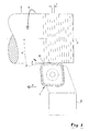
- FIG. 1 generally designates a cutting insert made in accordance with the invention, which insert, together with a bar or a shank 2, forms a turning tool.
- a workpiece designated 3 e.g., a shaft or the like, is rotatable around a centre axis C, more precisely in the direction of the arrow R.
- the workpiece is clamped in rotatable chucks, while the tool is movable along the workpiece, e.g., parallel to the centre axis C.
- the relative feeding direction between the tool and the workpiece is indicated by the arrow P.
- a chip removing, active major cutting edge 4 is included, the angle of which to the feeding direction P (which, per se, could form an angle to the geometrical centre axis C) constitutes the so-called setting angle ⁇ o of the edge.
- the feeding of the tool is designated f, while the cutting depth is designated a p .
- the cutting insert is of a polygonal, prismatic basic shape, and comprises a top side 7 that is parallel to a bottom side 8. Between the top and bottom side, a circumferential side surface extends, which is generally designated 9.
- edges 4, 6 consist of edges between the top side of the cutting insert and the clearance surfaces.
- the top side 7, which constitutes the chip-breaking part of the cutting insert is only schematically shown.
- the top side of the cutting insert does not contend to form a completed cutting-geometry surface.
- a flute-like depression S is illustrated, intended to serve as chip breaker.
- the cutting insert should include means in order to press a chip out of contact with the cutting insert as soon as possible after the separation of the chip from the workpiece.
- the cutting insert has a neutral or negative geometry, so far that all part surfaces included in the side surface 9 extend perpendicularly to the top and bottom sides 7, 8.
- the cutting insert could as well have a positive cutting geometry, i.e., be formed with a side surface that extends at an acute angle to the top side.
- the cutting insert may be double sided, i.e., be formed with a chip-breaking cutting geometry also on the bottom side 8 thereof.
- B designates a diagonal line between the corners 5, which forms a bisector of the pair of major cutting edges 4.
- a second bisector Ba extends between the two other, mutually diametrically opposed corners 5a of the cutting insert.
- four clearance edges 15 formed adjacent to the part surfaces 13 are included in the cutting insert, which clearance edges extend along the major part of each side of the cutting insert, more precisely from the individual edge 6 to an arched edge 16 adjacent to the convexly curved corner edge surface 14.
- an end edge 17 is present, which extends between nearby major cutting edges 4 at each one of the corners 5 (see also fig. 2).
- the angle ⁇ between the clearance edges 15 adjacent to the individual corner 5 is advantageously acute and amounts in the example shown to 80°. Accordingly, the angle ⁇ 1 between the individual clearance edge 15 and the bisector B is 40°. Hence it follows that the angle ⁇ is obtuse and amounts to 100°, the angle ⁇ 1 between the bisector Ba and the individual clearance edge 15 amounting to 50°.
- the radius of the corner edges 16 lacks importance.
- the angle ⁇ between the individual edge 6 and the bisector B is greater than the angle ⁇ 1 and amounts to 45° in the example.
- the angle ⁇ between the major cutting edge 4 and the bisector B is even greater and amounts to 55° in the example.
- the end edge 17 being inactive in normal circumstances may advantageously be straight and extend at a right angle ⁇ to the bisector B.
- the length L4 of the major cutting edge 4 may vary most considerably depending on the size of the cutting insert, desired cutting depth, and the amount of material that can be allowed to remain in a fillet. However, in practice, the measure L4 may be within the range of 0,5-2 mm, suitably 0,8-1,5 mm.
- the edge 6 is considerably shorter though, and may have a length L6 of about 0,3 mm. This measure may, however, be varied upward as well as downward.
- the length L17 of the end edge 17 is incidental in functional respect, but may in practice have approximately the same value as the edge length L4.
- the invention is based on the idea of not only making the major cutting edge 4 straight, but above all let the same transform into the surface finishing edge 6 via a sharp transition, which in the enlarged figures 5-7 is designated 18.
- sharp transition should be interpreted as the absence of any form of deliberately provided arc-shape of the edge in the point where the major cutting edge 4 transforms into the surface finishing edge 6. If the cutting insert is ground, the sharp transition 18 is provided by the clearance surfaces 11, 12 being ground in planes that extend at an obtuse angle (in the example 170°) to each other, the surfaces transforming into each other via a straight interruption line 19. In other words, the transition 18 is defined by the sharp or prismatic point where the edges 4 and 6 meet the interruption line 19.
- the surface finishing edge 6, like the major cutting edge 4, may be straight, at least adjacent to the sharp transition 18.
- the edge 6 is straight along the entire length L6 thereof, after which it transforms into a clearance edge 15 via a transition 20.
- the shape of this transition 20 is incidental, so far that it may be either sharp or softly rounded.
- the sharp transition 18 is formed in the same way, i.e., by an aim of letting the edges 4, 6 meet at a point that is intersected by an interruption line 19 between the clearance surfaces 11, 12.
- the transition may get a slight rounding due to the compression-moulding operation.
- unintentional roundness should, however, not have a radius exceeding 0,1 mm.
- the radius of the maximum roundness should not exceed 0,05 mm. Possible transitions having roundnesses below this value, e.g. 0,03 mm, are, however, to be considered as sharp.
- the transition 21 between the end edge 17 and the individual major cutting edge 4 is shown as a sharp transition of the same type as the transition 18.
- the transition is provided by the fact that the part surface 10 is planar and transforms into the planar part surface 11 via a straight interruption line 22 (see fig. 2), which extends through the point of intersection between the edge 4 and the end edge 17.
- a straight interruption line 22 see fig. 2
- fig. 5 which on a very enlarged scale shows the engagement of the major cutting edge 4 with the workpiece 3.
- the cutting depth a p is limited to the range of 0,05-0,3 mm and usually amounts to approx. 0,15 mm.
- the surface finishing, straight edge 6 is parallel to the feeding direction P (and in the example parallel to the geometrical rotation axis C of the workpiece).
- the major cutting edge 4 will remove chips (not shown) from the workpiece.
- the edge 4 By virtue of the edge 4 being straight all the way up to the transition 18, the chip will - irrespective of the width in question - be straight and equally thick along the entire width thereof, the chip in its entirety being removed in the direction perpendicular to the edge.
- crater wear is counteracted in close vicinity of the surface finishing edge 6, the serviceability of which is guaranteed during a long, effective operating period.
- the service life of the cutting insert is extended in comparison with turning inserts that in the critical area between the chip removing edge and the surface finishing edge include rounded edge portions, e.g., of the wiper type.
- the cutting insert according to the invention may be made from a variety of hard materials, such as cubic boron nitride, cemented carbide, ceramics, diamond, etc. However, primarily a manufacture based on cubic boron nitride (CBN) is expected.
- CBN cubic boron nitride
- the cutting insert is particularly suited for the machining of hard materials, such as hardened steel, the turning being effected while applying small cutting depths a p .
- the cutting insert offers a plurality of advantages, such as increased service life (by the reduction of the heat release), optimised chip shape, improved cutting-force directions, and a reduction of the residual stresses in the machined workpiece.
- setting angle essentially relates to the composed turning tool and the movement thereof in relation to the workpiece, rather than to an individual cutting insert as such. Because the surface finishing, straight edge 6 in the active state is set parallel to the feeding direction, the chip removing edge 4 forming a certain angle to a conceived line in the extension of the wiping edge, the concept of setting angle is, however, to be considered as relevant, in the preceding description as well as in the subsequent claims.
- the above-mentioned setting angle K constitutes the difference between the bisector angle ⁇ of the major cutting edge 4 and the bisector angle ⁇ of the surface finishing edge 6. In the example, this difference amounts to 10°. Although 10° constitute a preferred setting angle, the setting angle may be varied upward as well as downward. However, the setting angle should not exceed 30° and advantageously be below 20°. On the other hand, the setting angle should not be below 3°, preferably 5°. In practice, the setting angle of the majority of cutting inserts manufactured in accordance with the invention will be within the range of 5-15, suitably 8-12°.
Landscapes
- Engineering & Computer Science (AREA)
- Mechanical Engineering (AREA)
- Cutting Tools, Boring Holders, And Turrets (AREA)
- Milling Processes (AREA)
- Golf Clubs (AREA)
Abstract
Description
- Fig. 1
- is a schematic view showing a cutting insert according to the invention applied in a turning tool, as well as a rotary workpiece during machining,
- Fig. 2
- is an enlarged, schematic perspective view showing the cutting insert according to the invention,
- Fig. 3
- is a planar view of the cutting insert illustrating various geometrical data of the same,
- Fig. 4
- is an end view of the cutting insert according to fig. 3,
- Fig. 5
- is an additional enlarged, partial planar view of an active corner portion of the cutting insert during the machining of the workpiece,
- Figs. 6 and 7
- are additional partial planar views of one corner portion of the cutting insert.
Claims (9)
- Turning insert, comprising a corner (5) having two edges (4, 6) formed between a chip-breaking surface (7) and clearance surfaces (11, 12), a first one (4) of which edges is chip removing and a second (6) surface finishing, characterized in that the first edge (4) is straight and transforms into the second edge (6) via a sharp transition (18).
- Turning insert according to claim 1, characterized in that also the second, surface finishing edge (6) is straight.
- Turning insert according to claim 1 and 2, characterized in that the sharp transition (18) between said first and second edges (4, 6) is prismatic and provided by the fact that the clearance surfaces (11, 12) adjacent to the same are formed in planes extending at an obtuse angle to each other and transforming into each other via an interruption line (19), which intersects the meeting point between the edges.
- Turning insert according to any one of the preceding claims, characterized in that the first edge (4) has a setting angle (κ), such as the same is defined as the angle between said edge and a conceived straight line in the extension of the second edge (6), that amounts to at most 30°.
- Turning insert according to any one of the preceding claims, characterized in that the first edge (4) has a setting angle (K), such as this is defined as the angle between said edge and a conceived straight line in the extension of the second edge (6), that amounts to at least 3°.
- Turning insert according to any one of the preceding claims,
characterized in that the same comprises two diametrically opposed corners (5), which separately include a pair of identical first edges (4) together with co-operating second edges (6), the second edges (6) forming an acute angle (ε) to a bisector (B) of the same, while each one of the two first edges (4) forming an angle (γ) to the same bisector (B), which angle (γ) is greater than the first-mentioned angle (ε). - Turning insert according to claim 6, characterized in that between the two first edges (4), an end edge (17) extends, which is at least partially straight.
- Turning insert according to claim 7, characterized in that a transition (21) between the end edge (17) and each first edge (4) is sharp.
- Turning insert according to any one of claims 6-8, characterized in that, at the end thereof distanced from the first edge (4), the second edge (6) transforms into a clearance edge (15) that is straight and forms an angle (α1) to said bisector (B), which angle (α1) is smaller than the bisector angle (ε) of the second edges (6).
Applications Claiming Priority (2)
| Application Number | Priority Date | Filing Date | Title |
|---|---|---|---|
| SE0401245A SE528016C2 (en) | 2004-05-14 | 2004-05-14 | Lathe cut with a sharp transition between a first and a second edge |
| SE0401245 | 2004-05-14 |
Publications (3)
| Publication Number | Publication Date |
|---|---|
| EP1595625A2 true EP1595625A2 (en) | 2005-11-16 |
| EP1595625A3 EP1595625A3 (en) | 2009-05-20 |
| EP1595625B1 EP1595625B1 (en) | 2015-09-30 |
Family
ID=32390944
Family Applications (1)
| Application Number | Title | Priority Date | Filing Date |
|---|---|---|---|
| EP05445027.5A Expired - Lifetime EP1595625B1 (en) | 2004-05-14 | 2005-05-04 | Turning insert |
Country Status (6)
| Country | Link |
|---|---|
| US (1) | US7431540B2 (en) |
| EP (1) | EP1595625B1 (en) |
| JP (2) | JP2005324324A (en) |
| KR (1) | KR101384065B1 (en) |
| CN (1) | CN1695851B (en) |
| SE (1) | SE528016C2 (en) |
Cited By (2)
| Publication number | Priority date | Publication date | Assignee | Title |
|---|---|---|---|---|
| WO2017060026A1 (en) * | 2015-10-09 | 2017-04-13 | Sandvik Intellectual Property Ab | Turning insert and method |
| EP3417964A1 (en) | 2017-06-19 | 2018-12-26 | Sandvik Intellectual Property AB | Turning insert for metal cutting |
Families Citing this family (21)
| Publication number | Priority date | Publication date | Assignee | Title |
|---|---|---|---|---|
| JP2709914B2 (en) | 1995-11-24 | 1998-02-04 | 捷宏 田原 | Decorative plywood and its manufacturing method |
| JPWO2009034633A1 (en) * | 2007-09-13 | 2010-12-16 | 株式会社タンガロイ | Throw-away tip for radius cutter, and throw-away type radius cutter equipped with the tip |
| SE531855C2 (en) * | 2007-12-20 | 2009-08-25 | Seco Tools Ab | Indexable lathe insert and a cutting tool including such insert |
| USD635163S1 (en) * | 2008-06-26 | 2011-03-29 | Seco Tools Ab | Cutting insert for metal chip removal |
| JP2010125566A (en) * | 2008-11-28 | 2010-06-10 | Sumitomo Electric Ind Ltd | Cutting tip, cutting tool, and method for cutting hard-to-cut material |
| SE533269C2 (en) * | 2008-12-17 | 2010-08-03 | Sandvik Intellectual Property | Double-sided, indexable flat cutter |
| EP2450139B1 (en) * | 2009-06-29 | 2019-03-27 | Kyocera Corporation | Cutting insert, cutting tool, and manufacturing method for cut product using the same |
| WO2011024595A1 (en) * | 2009-08-31 | 2011-03-03 | 京セラ株式会社 | Cutting tool and production method for cut items using the same |
| JP5240623B2 (en) * | 2010-08-04 | 2013-07-17 | 住友電工ハードメタル株式会社 | Blade-tip-exchangeable tip and method for manufacturing the same |
| KR101838238B1 (en) * | 2011-01-27 | 2018-03-13 | 대구텍 유한회사 | Tangential cutting insert |
| KR20140039309A (en) | 2011-07-22 | 2014-04-01 | 케나메탈 인디아 리미티드 | An indexable drill insert |
| DE102012012980B4 (en) | 2011-07-22 | 2019-10-17 | Kennametal India Ltd. | drilling |
| DE102012014092B4 (en) | 2011-07-22 | 2020-12-17 | Kennametal India Ltd. | Indexable drill bit and drill body with indexable drill bit |
| CN103447591B (en) | 2012-05-28 | 2020-02-28 | 钴碳化钨硬质合金印度有限公司 | Quadrangular indexable drill insert |
| CN104540623B (en) * | 2012-08-10 | 2017-12-22 | 住友电工硬质合金株式会社 | Lathe Turning Tools |
| EP2926932B1 (en) * | 2012-11-30 | 2019-01-16 | Kyocera Corporation | Cutting insert, cutting tool, and cut workpiece manufacturing method |
| WO2014116571A1 (en) | 2013-01-23 | 2014-07-31 | Kennametal India Limited | Indexable drill insert and rotary cutting tool employing same |
| JP6457257B2 (en) * | 2014-12-18 | 2019-01-23 | Dmg森精機株式会社 | Milling tool and machining method using the same |
| JP7040657B1 (en) * | 2021-03-10 | 2022-03-23 | 株式会社タンガロイ | Cutting inserts and turning tools |
| WO2025186972A1 (en) * | 2024-03-07 | 2025-09-12 | 住友電工ハードメタル株式会社 | Cutting insert |
| EP4670877A1 (en) * | 2024-06-28 | 2025-12-31 | AB Sandvik Coromant | Cutting insert for turning and turning tool |
Family Cites Families (20)
| Publication number | Priority date | Publication date | Assignee | Title |
|---|---|---|---|---|
| GB951624A (en) * | 1959-06-17 | 1964-03-11 | Sandvikens Jernverks Ab | Improvements in or relating to inserts for cutting tools |
| DE1272684B (en) * | 1965-07-02 | 1968-07-11 | Montanwerke Walter Ges Mit Bes | Insert milling head |
| FR2172542A5 (en) * | 1972-02-17 | 1973-09-28 | Ballesteros Daniel | |
| SE382769B (en) * | 1974-05-24 | 1976-02-16 | Seco Tools Ab | FRIENDS FOR MILLING TOOLS |
| SE448431B (en) * | 1985-07-03 | 1987-02-23 | Santrade Ltd | REQUEST FOR TEAM DISPOSAL PROCESSING |
| JPS62208817A (en) * | 1986-03-07 | 1987-09-14 | Kobe Steel Ltd | Insert chip for milling cutter |
| SE463658B (en) * | 1987-10-19 | 1991-01-07 | Seco Tools Ab | SHOULD BE REPLACED |
| JPH0432802U (en) * | 1990-07-13 | 1992-03-17 | ||
| SE502261C2 (en) * | 1991-03-04 | 1995-09-25 | Sandvik Ab | Scale turning tools provided with polygonal rough cutters and finished cutters |
| US5226761A (en) * | 1991-09-27 | 1993-07-13 | Iscar Ltd. | Metal cutting insert and metal cutting tool utilizing the metal cutting insert |
| IL103008A (en) * | 1992-09-01 | 1996-12-05 | Iscar Ltd | Cutting insert for a milling cutter tool |
| SE509224C2 (en) * | 1994-05-19 | 1998-12-21 | Sandvik Ab | Inserts |
| IL110785A (en) * | 1994-08-25 | 1998-04-05 | Iscar Ltd | Cutting insert for a rotary milling cutter |
| JP3970929B2 (en) * | 1996-01-31 | 2007-09-05 | ヴィディア ゲゼルシャフト ミット ベシュレンクテル ハフツング | Cutting tips for roughing and precision cutting |
| SE515070C2 (en) * | 1999-10-22 | 2001-06-05 | Sandvik Ab | Double negative cutting tool for chip separating machining |
| DE60041320D1 (en) * | 1999-11-25 | 2009-02-26 | Sumitomo Electric Industries | Cutting tool made of polycrystalline carbide |
| AT4435U1 (en) * | 2000-09-25 | 2001-07-25 | Plansee Tizit Ag | TURNING INSERT TO TURN |
| JP2004034164A (en) * | 2002-06-28 | 2004-02-05 | Toyota Central Res & Dev Lab Inc | Cutting tools for peeling |
| JP4121449B2 (en) * | 2003-01-16 | 2008-07-23 | 日本特殊陶業株式会社 | Throw away tip and bite |
| SE527378C2 (en) | 2003-05-08 | 2006-02-21 | Sandvik Intellectual Property | Cutters for turning have an edge phase |
-
2004
- 2004-05-14 SE SE0401245A patent/SE528016C2/en unknown
-
2005
- 2005-05-04 EP EP05445027.5A patent/EP1595625B1/en not_active Expired - Lifetime
- 2005-05-12 US US11/127,141 patent/US7431540B2/en not_active Expired - Lifetime
- 2005-05-13 KR KR1020050040308A patent/KR101384065B1/en not_active Expired - Fee Related
- 2005-05-16 JP JP2005142499A patent/JP2005324324A/en not_active Withdrawn
- 2005-05-16 CN CN2005100726565A patent/CN1695851B/en not_active Expired - Fee Related
-
2011
- 2011-10-13 JP JP2011225723A patent/JP5529826B2/en not_active Expired - Fee Related
Cited By (5)
| Publication number | Priority date | Publication date | Assignee | Title |
|---|---|---|---|---|
| WO2017060026A1 (en) * | 2015-10-09 | 2017-04-13 | Sandvik Intellectual Property Ab | Turning insert and method |
| US9737935B2 (en) | 2015-10-09 | 2017-08-22 | Sandvik Intellectual Property Ab | Turning insert |
| EP3417964A1 (en) | 2017-06-19 | 2018-12-26 | Sandvik Intellectual Property AB | Turning insert for metal cutting |
| WO2018233861A1 (en) | 2017-06-19 | 2018-12-27 | Sandvik Intellectual Property Ab | TURNING PLATE FOR METAL CUTTING |
| US11623283B2 (en) | 2017-06-19 | 2023-04-11 | Sandvik Intellectual Property Ab | Turning insert for metal cutting |
Also Published As
| Publication number | Publication date |
|---|---|
| SE528016C2 (en) | 2006-08-08 |
| JP2005324324A (en) | 2005-11-24 |
| US7431540B2 (en) | 2008-10-07 |
| KR20060047915A (en) | 2006-05-18 |
| EP1595625A3 (en) | 2009-05-20 |
| CN1695851A (en) | 2005-11-16 |
| JP2012006145A (en) | 2012-01-12 |
| EP1595625B1 (en) | 2015-09-30 |
| US20060039763A1 (en) | 2006-02-23 |
| SE0401245L (en) | 2005-11-15 |
| SE0401245D0 (en) | 2004-05-14 |
| JP5529826B2 (en) | 2014-06-25 |
| CN1695851B (en) | 2010-05-26 |
| KR101384065B1 (en) | 2014-04-09 |
Similar Documents
| Publication | Publication Date | Title |
|---|---|---|
| EP1595625B1 (en) | Turning insert | |
| US6543970B1 (en) | Double negative cutting insert for tools for chip removing machining | |
| EP1349691B1 (en) | Indexable milling insert | |
| CN101579755B (en) | Milling insert | |
| CN101096057B (en) | Face-milling insert | |
| JP5698311B2 (en) | Milling insert | |
| CN1117646C (en) | Indexable insert for end mills | |
| CN1107567C (en) | Indexable insert for rotary milling tools | |
| EP1297921B1 (en) | Turning insert | |
| EP2114596B1 (en) | A negative insert for cutting machining | |
| US6530726B2 (en) | Cutting insert having improved cutting | |
| US5454670A (en) | Throw-away insert and face milling cutter | |
| CN101745675A (en) | Double-sided, indexable face milling insert | |
| CZ299732B6 (en) | Large-feed British milling insert | |
| JP3759750B2 (en) | Threading method and cutting insert for it | |
| WO1998007543A9 (en) | Insert having variable width land | |
| JP2008512252A (en) | Turning tools, turning inserts for turning tools, and integrated turning tools | |
| JP3638603B2 (en) | Throwaway tip | |
| KR100299471B1 (en) | Cutting insert with twisted relief surface | |
| JPH065041Y2 (en) | Throwaway tip | |
| JPH07204921A (en) | End mill | |
| CA2254233A1 (en) | T-landed insert | |
| JP3833875B2 (en) | Ball end mill | |
| JPH05253719A (en) | Drill |
Legal Events
| Date | Code | Title | Description |
|---|---|---|---|
| PUAI | Public reference made under article 153(3) epc to a published international application that has entered the european phase |
Free format text: ORIGINAL CODE: 0009012 |
|
| AK | Designated contracting states |
Kind code of ref document: A2 Designated state(s): AT BE BG CH CY CZ DE DK EE ES FI FR GB GR HU IE IS IT LI LT LU MC NL PL PT RO SE SI SK TR |
|
| AX | Request for extension of the european patent |
Extension state: AL BA HR LV MK YU |
|
| PUAL | Search report despatched |
Free format text: ORIGINAL CODE: 0009013 |
|
| AK | Designated contracting states |
Kind code of ref document: A3 Designated state(s): AT BE BG CH CY CZ DE DK EE ES FI FR GB GR HU IE IS IT LI LT LU MC NL PL PT RO SE SI SK TR |
|
| AX | Request for extension of the european patent |
Extension state: AL BA HR LV MK YU |
|
| 17P | Request for examination filed |
Effective date: 20090604 |
|
| AKX | Designation fees paid |
Designated state(s): AT BE BG CH CY CZ DE DK EE ES FI FR GB GR HU IE IS IT LI LT LU MC NL PL PT RO SE SI SK TR |
|
| 17Q | First examination report despatched |
Effective date: 20100706 |
|
| RAP1 | Party data changed (applicant data changed or rights of an application transferred) |
Owner name: SANDVIK INTELLECTUAL PROPERTY AB |
|
| GRAP | Despatch of communication of intention to grant a patent |
Free format text: ORIGINAL CODE: EPIDOSNIGR1 |
|
| GRAP | Despatch of communication of intention to grant a patent |
Free format text: ORIGINAL CODE: EPIDOSNIGR1 |
|
| INTG | Intention to grant announced |
Effective date: 20150520 |
|
| INTG | Intention to grant announced |
Effective date: 20150612 |
|
| GRAS | Grant fee paid |
Free format text: ORIGINAL CODE: EPIDOSNIGR3 |
|
| GRAA | (expected) grant |
Free format text: ORIGINAL CODE: 0009210 |
|
| AK | Designated contracting states |
Kind code of ref document: B1 Designated state(s): AT BE BG CH CY CZ DE DK EE ES FI FR GB GR HU IE IS IT LI LT LU MC NL PL PT RO SE SI SK TR |
|
| REG | Reference to a national code |
Ref country code: CH Ref legal event code: EP Ref country code: GB Ref legal event code: FG4D |
|
| REG | Reference to a national code |
Ref country code: AT Ref legal event code: REF Ref document number: 752091 Country of ref document: AT Kind code of ref document: T Effective date: 20151015 |
|
| REG | Reference to a national code |
Ref country code: IE Ref legal event code: FG4D |
|
| REG | Reference to a national code |
Ref country code: DE Ref legal event code: R096 Ref document number: 602005047595 Country of ref document: DE |
|
| PG25 | Lapsed in a contracting state [announced via postgrant information from national office to epo] |
Ref country code: FI Free format text: LAPSE BECAUSE OF FAILURE TO SUBMIT A TRANSLATION OF THE DESCRIPTION OR TO PAY THE FEE WITHIN THE PRESCRIBED TIME-LIMIT Effective date: 20150930 Ref country code: GR Free format text: LAPSE BECAUSE OF FAILURE TO SUBMIT A TRANSLATION OF THE DESCRIPTION OR TO PAY THE FEE WITHIN THE PRESCRIBED TIME-LIMIT Effective date: 20151231 Ref country code: LT Free format text: LAPSE BECAUSE OF FAILURE TO SUBMIT A TRANSLATION OF THE DESCRIPTION OR TO PAY THE FEE WITHIN THE PRESCRIBED TIME-LIMIT Effective date: 20150930 |
|
| REG | Reference to a national code |
Ref country code: NL Ref legal event code: MP Effective date: 20150930 |
|
| REG | Reference to a national code |
Ref country code: LT Ref legal event code: MG4D |
|
| REG | Reference to a national code |
Ref country code: AT Ref legal event code: MK05 Ref document number: 752091 Country of ref document: AT Kind code of ref document: T Effective date: 20150930 |
|
| PG25 | Lapsed in a contracting state [announced via postgrant information from national office to epo] |
Ref country code: SE Free format text: LAPSE BECAUSE OF FAILURE TO SUBMIT A TRANSLATION OF THE DESCRIPTION OR TO PAY THE FEE WITHIN THE PRESCRIBED TIME-LIMIT Effective date: 20150930 |
|
| REG | Reference to a national code |
Ref country code: FR Ref legal event code: PLFP Year of fee payment: 12 |
|
| PG25 | Lapsed in a contracting state [announced via postgrant information from national office to epo] |
Ref country code: CZ Free format text: LAPSE BECAUSE OF FAILURE TO SUBMIT A TRANSLATION OF THE DESCRIPTION OR TO PAY THE FEE WITHIN THE PRESCRIBED TIME-LIMIT Effective date: 20150930 Ref country code: NL Free format text: LAPSE BECAUSE OF FAILURE TO SUBMIT A TRANSLATION OF THE DESCRIPTION OR TO PAY THE FEE WITHIN THE PRESCRIBED TIME-LIMIT Effective date: 20150930 Ref country code: ES Free format text: LAPSE BECAUSE OF FAILURE TO SUBMIT A TRANSLATION OF THE DESCRIPTION OR TO PAY THE FEE WITHIN THE PRESCRIBED TIME-LIMIT Effective date: 20150930 Ref country code: IS Free format text: LAPSE BECAUSE OF FAILURE TO SUBMIT A TRANSLATION OF THE DESCRIPTION OR TO PAY THE FEE WITHIN THE PRESCRIBED TIME-LIMIT Effective date: 20160130 Ref country code: SK Free format text: LAPSE BECAUSE OF FAILURE TO SUBMIT A TRANSLATION OF THE DESCRIPTION OR TO PAY THE FEE WITHIN THE PRESCRIBED TIME-LIMIT Effective date: 20150930 Ref country code: EE Free format text: LAPSE BECAUSE OF FAILURE TO SUBMIT A TRANSLATION OF THE DESCRIPTION OR TO PAY THE FEE WITHIN THE PRESCRIBED TIME-LIMIT Effective date: 20150930 |
|
| PG25 | Lapsed in a contracting state [announced via postgrant information from national office to epo] |
Ref country code: RO Free format text: LAPSE BECAUSE OF FAILURE TO SUBMIT A TRANSLATION OF THE DESCRIPTION OR TO PAY THE FEE WITHIN THE PRESCRIBED TIME-LIMIT Effective date: 20150930 Ref country code: PT Free format text: LAPSE BECAUSE OF FAILURE TO SUBMIT A TRANSLATION OF THE DESCRIPTION OR TO PAY THE FEE WITHIN THE PRESCRIBED TIME-LIMIT Effective date: 20160201 Ref country code: PL Free format text: LAPSE BECAUSE OF FAILURE TO SUBMIT A TRANSLATION OF THE DESCRIPTION OR TO PAY THE FEE WITHIN THE PRESCRIBED TIME-LIMIT Effective date: 20150930 Ref country code: AT Free format text: LAPSE BECAUSE OF FAILURE TO SUBMIT A TRANSLATION OF THE DESCRIPTION OR TO PAY THE FEE WITHIN THE PRESCRIBED TIME-LIMIT Effective date: 20150930 |
|
| REG | Reference to a national code |
Ref country code: DE Ref legal event code: R097 Ref document number: 602005047595 Country of ref document: DE |
|
| PLBE | No opposition filed within time limit |
Free format text: ORIGINAL CODE: 0009261 |
|
| STAA | Information on the status of an ep patent application or granted ep patent |
Free format text: STATUS: NO OPPOSITION FILED WITHIN TIME LIMIT |
|
| PG25 | Lapsed in a contracting state [announced via postgrant information from national office to epo] |
Ref country code: DK Free format text: LAPSE BECAUSE OF FAILURE TO SUBMIT A TRANSLATION OF THE DESCRIPTION OR TO PAY THE FEE WITHIN THE PRESCRIBED TIME-LIMIT Effective date: 20150930 Ref country code: BE Free format text: LAPSE BECAUSE OF NON-PAYMENT OF DUE FEES Effective date: 20160531 |
|
| 26N | No opposition filed |
Effective date: 20160701 |
|
| PG25 | Lapsed in a contracting state [announced via postgrant information from national office to epo] |
Ref country code: SI Free format text: LAPSE BECAUSE OF FAILURE TO SUBMIT A TRANSLATION OF THE DESCRIPTION OR TO PAY THE FEE WITHIN THE PRESCRIBED TIME-LIMIT Effective date: 20150930 |
|
| PG25 | Lapsed in a contracting state [announced via postgrant information from national office to epo] |
Ref country code: BE Free format text: LAPSE BECAUSE OF FAILURE TO SUBMIT A TRANSLATION OF THE DESCRIPTION OR TO PAY THE FEE WITHIN THE PRESCRIBED TIME-LIMIT Effective date: 20150930 Ref country code: LU Free format text: LAPSE BECAUSE OF FAILURE TO SUBMIT A TRANSLATION OF THE DESCRIPTION OR TO PAY THE FEE WITHIN THE PRESCRIBED TIME-LIMIT Effective date: 20160504 |
|
| REG | Reference to a national code |
Ref country code: CH Ref legal event code: PL |
|
| PG25 | Lapsed in a contracting state [announced via postgrant information from national office to epo] |
Ref country code: LI Free format text: LAPSE BECAUSE OF NON-PAYMENT OF DUE FEES Effective date: 20160531 Ref country code: CH Free format text: LAPSE BECAUSE OF NON-PAYMENT OF DUE FEES Effective date: 20160531 |
|
| REG | Reference to a national code |
Ref country code: IE Ref legal event code: MM4A |
|
| REG | Reference to a national code |
Ref country code: FR Ref legal event code: PLFP Year of fee payment: 13 |
|
| PG25 | Lapsed in a contracting state [announced via postgrant information from national office to epo] |
Ref country code: IE Free format text: LAPSE BECAUSE OF NON-PAYMENT OF DUE FEES Effective date: 20160504 |
|
| REG | Reference to a national code |
Ref country code: FR Ref legal event code: PLFP Year of fee payment: 14 |
|
| PG25 | Lapsed in a contracting state [announced via postgrant information from national office to epo] |
Ref country code: CY Free format text: LAPSE BECAUSE OF FAILURE TO SUBMIT A TRANSLATION OF THE DESCRIPTION OR TO PAY THE FEE WITHIN THE PRESCRIBED TIME-LIMIT Effective date: 20150930 Ref country code: HU Free format text: LAPSE BECAUSE OF FAILURE TO SUBMIT A TRANSLATION OF THE DESCRIPTION OR TO PAY THE FEE WITHIN THE PRESCRIBED TIME-LIMIT; INVALID AB INITIO Effective date: 20050504 |
|
| PG25 | Lapsed in a contracting state [announced via postgrant information from national office to epo] |
Ref country code: MC Free format text: LAPSE BECAUSE OF FAILURE TO SUBMIT A TRANSLATION OF THE DESCRIPTION OR TO PAY THE FEE WITHIN THE PRESCRIBED TIME-LIMIT Effective date: 20150930 Ref country code: TR Free format text: LAPSE BECAUSE OF FAILURE TO SUBMIT A TRANSLATION OF THE DESCRIPTION OR TO PAY THE FEE WITHIN THE PRESCRIBED TIME-LIMIT Effective date: 20150930 |
|
| PG25 | Lapsed in a contracting state [announced via postgrant information from national office to epo] |
Ref country code: BG Free format text: LAPSE BECAUSE OF FAILURE TO SUBMIT A TRANSLATION OF THE DESCRIPTION OR TO PAY THE FEE WITHIN THE PRESCRIBED TIME-LIMIT Effective date: 20150930 |
|
| P01 | Opt-out of the competence of the unified patent court (upc) registered |
Effective date: 20230603 |
|
| PGFP | Annual fee paid to national office [announced via postgrant information from national office to epo] |
Ref country code: IT Payment date: 20230412 Year of fee payment: 19 Ref country code: FR Payment date: 20230421 Year of fee payment: 19 Ref country code: DE Payment date: 20230404 Year of fee payment: 19 |
|
| PGFP | Annual fee paid to national office [announced via postgrant information from national office to epo] |
Ref country code: GB Payment date: 20230406 Year of fee payment: 19 |
|
| REG | Reference to a national code |
Ref country code: DE Ref legal event code: R119 Ref document number: 602005047595 Country of ref document: DE |
|
| GBPC | Gb: european patent ceased through non-payment of renewal fee |
Effective date: 20240504 |
|
| PG25 | Lapsed in a contracting state [announced via postgrant information from national office to epo] |
Ref country code: DE Free format text: LAPSE BECAUSE OF NON-PAYMENT OF DUE FEES Effective date: 20241203 |
|
| PG25 | Lapsed in a contracting state [announced via postgrant information from national office to epo] |
Ref country code: FR Free format text: LAPSE BECAUSE OF NON-PAYMENT OF DUE FEES Effective date: 20240531 |
|
| PG25 | Lapsed in a contracting state [announced via postgrant information from national office to epo] |
Ref country code: GB Free format text: LAPSE BECAUSE OF NON-PAYMENT OF DUE FEES Effective date: 20240504 Ref country code: IT Free format text: LAPSE BECAUSE OF NON-PAYMENT OF DUE FEES Effective date: 20240504 |