EP1595495B1 - Dental device for examining optical characteristics of dental tissue - Google Patents
Dental device for examining optical characteristics of dental tissue Download PDFInfo
- Publication number
- EP1595495B1 EP1595495B1 EP05010492A EP05010492A EP1595495B1 EP 1595495 B1 EP1595495 B1 EP 1595495B1 EP 05010492 A EP05010492 A EP 05010492A EP 05010492 A EP05010492 A EP 05010492A EP 1595495 B1 EP1595495 B1 EP 1595495B1
- Authority
- EP
- European Patent Office
- Prior art keywords
- handpiece
- radiation
- sleeve
- probe
- dental
- Prior art date
- Legal status (The legal status is an assumption and is not a legal conclusion. Google has not performed a legal analysis and makes no representation as to the accuracy of the status listed.)
- Active
Links
- 230000003287 optical effect Effects 0.000 title claims description 18
- 230000005855 radiation Effects 0.000 claims description 100
- 230000004044 response Effects 0.000 claims description 57
- 239000000523 sample Substances 0.000 claims description 54
- 230000005284 excitation Effects 0.000 claims description 48
- 238000005259 measurement Methods 0.000 claims description 24
- 238000011156 evaluation Methods 0.000 claims description 17
- 239000000463 material Substances 0.000 claims description 13
- 238000001514 detection method Methods 0.000 claims description 12
- 238000003745 diagnosis Methods 0.000 claims description 8
- 208000002925 dental caries Diseases 0.000 claims description 7
- 239000004020 conductor Substances 0.000 claims description 6
- 208000006558 Dental Calculus Diseases 0.000 claims description 4
- 230000004913 activation Effects 0.000 claims description 4
- 238000011835 investigation Methods 0.000 claims description 2
- 208000035143 Bacterial infection Diseases 0.000 claims 1
- 208000022362 bacterial infectious disease Diseases 0.000 claims 1
- 239000000835 fiber Substances 0.000 description 23
- 230000005540 biological transmission Effects 0.000 description 19
- 230000006870 function Effects 0.000 description 11
- 238000004140 cleaning Methods 0.000 description 5
- 239000000126 substance Substances 0.000 description 5
- 230000003213 activating effect Effects 0.000 description 4
- 230000008901 benefit Effects 0.000 description 4
- 238000013461 design Methods 0.000 description 4
- 238000000034 method Methods 0.000 description 4
- 239000013307 optical fiber Substances 0.000 description 4
- 230000001954 sterilising effect Effects 0.000 description 4
- 206010061217 Infestation Diseases 0.000 description 3
- 230000001580 bacterial effect Effects 0.000 description 3
- 230000008878 coupling Effects 0.000 description 3
- 238000010168 coupling process Methods 0.000 description 3
- 238000005859 coupling reaction Methods 0.000 description 3
- 210000003128 head Anatomy 0.000 description 3
- 230000033001 locomotion Effects 0.000 description 3
- 210000000214 mouth Anatomy 0.000 description 3
- 238000003825 pressing Methods 0.000 description 3
- 230000008569 process Effects 0.000 description 3
- 238000002604 ultrasonography Methods 0.000 description 3
- 241000209035 Ilex Species 0.000 description 2
- 208000005888 Periodontal Pocket Diseases 0.000 description 2
- 238000012937 correction Methods 0.000 description 2
- 238000011161 development Methods 0.000 description 2
- 230000018109 developmental process Effects 0.000 description 2
- 238000002405 diagnostic procedure Methods 0.000 description 2
- 230000003670 easy-to-clean Effects 0.000 description 2
- 238000012376 hot air sterilization Methods 0.000 description 2
- 238000003384 imaging method Methods 0.000 description 2
- 238000003780 insertion Methods 0.000 description 2
- 230000037431 insertion Effects 0.000 description 2
- 238000012545 processing Methods 0.000 description 2
- 238000001055 reflectance spectroscopy Methods 0.000 description 2
- 239000007921 spray Substances 0.000 description 2
- 238000004659 sterilization and disinfection Methods 0.000 description 2
- 239000012780 transparent material Substances 0.000 description 2
- OKTJSMMVPCPJKN-UHFFFAOYSA-N Carbon Chemical compound [C] OKTJSMMVPCPJKN-UHFFFAOYSA-N 0.000 description 1
- XUIMIQQOPSSXEZ-UHFFFAOYSA-N Silicon Chemical compound [Si] XUIMIQQOPSSXEZ-UHFFFAOYSA-N 0.000 description 1
- 238000009825 accumulation Methods 0.000 description 1
- 230000009471 action Effects 0.000 description 1
- 229910052799 carbon Inorganic materials 0.000 description 1
- 230000008859 change Effects 0.000 description 1
- 238000004891 communication Methods 0.000 description 1
- 230000003247 decreasing effect Effects 0.000 description 1
- 239000005548 dental material Substances 0.000 description 1
- 230000001419 dependent effect Effects 0.000 description 1
- 238000010586 diagram Methods 0.000 description 1
- 230000002349 favourable effect Effects 0.000 description 1
- 238000005286 illumination Methods 0.000 description 1
- 238000007689 inspection Methods 0.000 description 1
- 239000011810 insulating material Substances 0.000 description 1
- 230000004807 localization Effects 0.000 description 1
- 238000004519 manufacturing process Methods 0.000 description 1
- 239000006187 pill Substances 0.000 description 1
- 230000001681 protective effect Effects 0.000 description 1
- 229910052594 sapphire Inorganic materials 0.000 description 1
- 239000010980 sapphire Substances 0.000 description 1
- 229910052710 silicon Inorganic materials 0.000 description 1
- 239000010703 silicon Substances 0.000 description 1
- 230000003595 spectral effect Effects 0.000 description 1
- 238000001228 spectrum Methods 0.000 description 1
- 238000003860 storage Methods 0.000 description 1
- 230000001502 supplementing effect Effects 0.000 description 1
- 238000011144 upstream manufacturing Methods 0.000 description 1
Images


Classifications
-
- A—HUMAN NECESSITIES
- A61—MEDICAL OR VETERINARY SCIENCE; HYGIENE
- A61B—DIAGNOSIS; SURGERY; IDENTIFICATION
- A61B5/00—Measuring for diagnostic purposes; Identification of persons
- A61B5/0059—Measuring for diagnostic purposes; Identification of persons using light, e.g. diagnosis by transillumination, diascopy, fluorescence
- A61B5/0082—Measuring for diagnostic purposes; Identification of persons using light, e.g. diagnosis by transillumination, diascopy, fluorescence adapted for particular medical purposes
- A61B5/0088—Measuring for diagnostic purposes; Identification of persons using light, e.g. diagnosis by transillumination, diascopy, fluorescence adapted for particular medical purposes for oral or dental tissue
-
- A—HUMAN NECESSITIES
- A61—MEDICAL OR VETERINARY SCIENCE; HYGIENE
- A61B—DIAGNOSIS; SURGERY; IDENTIFICATION
- A61B5/00—Measuring for diagnostic purposes; Identification of persons
- A61B5/74—Details of notification to user or communication with user or patient ; user input means
- A61B5/742—Details of notification to user or communication with user or patient ; user input means using visual displays
-
- A—HUMAN NECESSITIES
- A61—MEDICAL OR VETERINARY SCIENCE; HYGIENE
- A61B—DIAGNOSIS; SURGERY; IDENTIFICATION
- A61B2562/00—Details of sensors; Constructional details of sensor housings or probes; Accessories for sensors
- A61B2562/24—Hygienic packaging for medical sensors; Maintaining apparatus for sensor hygiene
- A61B2562/247—Hygienic covers, i.e. for covering the sensor or apparatus during use
-
- A—HUMAN NECESSITIES
- A61—MEDICAL OR VETERINARY SCIENCE; HYGIENE
- A61B—DIAGNOSIS; SURGERY; IDENTIFICATION
- A61B5/00—Measuring for diagnostic purposes; Identification of persons
- A61B5/0002—Remote monitoring of patients using telemetry, e.g. transmission of vital signals via a communication network
Definitions
- the present invention relates to a dental device for examining the optical properties of tooth tissue according to the preamble of claim 1. More particularly, the present invention relates to a device for detecting fluorescent substances on teeth, for example caries, plaque, bacterial infestation, concrements or tartar.
- optical examination devices with the aid of which, for example, caries, plaque, bacterial infestation, concrements or tartar can be recognized, have been known for some time and in different variants. All known devices have in common that a tooth tissue region to be examined is first irradiated with an excitation radiation, whereupon a response radiation is emitted by the tooth. This response radiation may include both the reflected back radiation of the same wavelength and fluorescence radiation. The response radiation is again detected and fed to an evaluation unit, which determines based on the spectrum of the response radiation, whether one of the above substances is present or not.
- the known optical diagnostic methods and devices differ in this case by the wavelength (s) used for the excitation radiation and by the evaluation of the detected response radiation.
- a first possibility is to investigate whether fluorescence radiation has arisen on the tooth in response to the excitation radiation. Another possibility exists in the so-called reflection spectrometry to investigate which wavelengths are reflected by the tooth surface in which way.
- Devices of this type are for example in the DE 297 04 185 U1 , of the DE 197 09 500 C1 or the DE 100 13 210 A1 described.
- These known devices comprise a dental handpiece with an examination probe, via which the excitation radiation is directed onto the tooth to be examined and the response radiation reflected back from the tooth is detected.
- the light source for generating the excitation radiation is often arranged directly in the handpiece, whereas the evaluation of the response radiation is predominantly carried out in a console, which is connected via a connecting hose with the handpiece.
- This console has on the one hand, the electronics for controlling the light source for the excitation radiation and for the evaluation of Response radiation on.
- display means in the form of a display are provided on the console, which display the measurement result and thus provide information as to whether the region just examined has one of the abovementioned fluorescent substances or not.
- a dental device for examining optical properties of tooth tissue in which a light device illuminates the tooth to be examined and the reflected light is detected by an imaging system.
- a processor processes the data captured by the imaging system.
- the device At its front end region, the device has a shield.
- a dental device for examining optical properties of tooth tissue which has a removable sleeve of sterilizable material in its front region.
- a corresponding device is known in which the front region is provided with a protective cover.
- an intraoral device for curing dental materials has a switch as well as a hygiene envelope through which the switch can be operated.
- the present invention is based on the object to further improve the handling of previously known dental optical examination devices. It should be noted that it should be possible for a user of the device to examine even inaccessible areas within the oral cavity of a patient. Furthermore, there should be the possibility of simple cleaning, since in particular those parts which enter the oral cavity of the patient must also be sterilized. The problem is solved by the invention defined in the independent claim 1.
- the dental examination device prefferably design such that it is formed by a hand-held device, which can be used in principle completely independent of other facilities and has all the essential and necessary for performing the optical diagnostic method elements.
- the optical examination device Due to the configuration of the optical examination device as an autonomously operating handpiece, the user of the device is no longer restricted in his range of motion. The handling of the device is thus in Compared to the known devices in which the handpiece is connected via a supply hose to a console, significantly improved.
- the measurement results produced by the examination device for the purpose of supplementing or further processing are transmitted wirelessly to an external presentation and / or evaluation unit.
- This external unit may be, for example, a PC within a dental practice in which the measurement results created during the examination are automatically stored and assigned to the corresponding patient.
- this external unit for additional representation of the measurement result - for example, using a dental chart - are used.
- the transmission of the signals can take place in the form of electromagnetic signals, by means of ultrasound or other known wireless transmission techniques.
- the present invention further deals with the problem of cleaning or sterilization of the examination device.
- a simple cleaning should be possible, since there are high hygiene requirements in dental practices. Since at least the front part of the examination device enters the oral cavity of the patient, there should in particular be the possibility of sterilizing this area.
- the handpiece in which the elements of the optical inspection device are arranged, at least in its front region with a sleeve which is removable and consists of a sterilizable material. Since in this solution only the sleeve and the examination probe required for the transmission of the excitation and radiation radiation come into contact with the patient, the probe and the sleeve can be removed from the handpiece and sterilized separately after an examination, in particular those for controlling the light source and evaluation of the response radiation required electronic components of the device remain in the non-clean area of the handpiece and are therefore not burdened.
- the sleeve has parts of a switching element for activating the device or the means for generating the excitation radiation.
- the switching element is a ring switch which has an electrical line extending in the interior of the handpiece, which is in the region of Ring switch is interrupted.
- the removable sleeve has an actuatable element with a bridging element made of a conductive material, via which the line can be closed and thus the handpiece or the means for generating the excitation radiation can be activated.
- the actuatable element is a switching cap made of a flexible material.
- the removable sleeve is preferably placed on the handpiece from the front, wherein it can be provided in particular that the sleeve can be pushed or removed only when the intended for the transmission of excitation and response radiation diagnostic probe is removed from the handpiece.
- This probe is also preferably releasably attached to the front handpiece end, in particular latched and can be rotatably mounted. In this case, it can also be provided to provide differently designed diagnostic probes, which couple the light of the excitation and response radiation according to the area that is currently being investigated in each case in a certain way and decoupled. This opens up the possibility of the examination device according to the invention, e.g. both for examining occlusal surfaces and for examination in periodontal pockets and interdental spaces.
- a further aspect is concerned with the problem of making the elements required for detecting the response radiation reflected by the tooth surface as compact as possible so that they can be integrated into the handpiece to save space.
- a provided for detecting the response radiation photodiode within a small housing which is inserted into the handpiece.
- the transmission of the response radiation to the photodiode is effected via a light guide, at one end of which the photodiode is arranged.
- the housing can have an opening into which the light guide opens, wherein in particular a snap-action closure for fastening the light guide can be arranged on the housing.
- a filter arranged between the optical waveguide end and the photodiode is provided within the housing, which transmits only the wavelengths required for evaluating the response radiation.
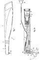
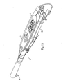
- Fig. 1 shows the outside view of a first embodiment of a dental device according to the invention for examining tooth tissue, in particular for the detection of caries, plaque, bacterial infestation, concrements or tartar.
- the device is designed as a handpiece 1, which according to the first concept of the invention can be used completely independently of other external consoles or evaluation and display units.
- the elongated handle body 2 has in its front head region 3 a probe 10 which projects slightly laterally downwards and which is provided for transmitting an excitation radiation to the tooth tissue region to be examined and for transmitting the response radiation reflected back from the tooth to an evaluation unit arranged in the handpiece 1 is.
- This probe 10 will be explained later in detail.
- a ring switch 5 is further provided, which can be used to activate the excitation radiation source.
- this ring switch 5 is part of a detachable from the handpiece 1 to the front sleeve, whereby a simple cleaning and sterilizing those parts of the handpiece 1, which come into contact with the patient, is made possible.
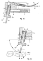
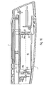
- the Fig. 2a to 2c show those components of the examination device, which are required for the recognition of the above-mentioned materials in a examined tooth tissue area.
- the examination is carried out by exposing the tooth tissue to be examined to an excitation radiation and detecting and evaluating the response radiation resulting from the irradiation.
- the essential components of the handpiece 1 are thus firstly a light source for generating the excitation radiation, evaluation means for evaluating the response radiation, and means for transmitting the excitation radiation to the area to be examined and for transmitting the response radiation to the evaluation means.
- the light source for generating the excitation radiation is formed by a laser diode 20, which generates an almost monochromatic light.
- the excitation radiation in the range between 600 nm and 670 nm, preferably at about 655 nm, since at such a wavelength the best possible compromise between the output power of the laser diode 20 and the spectral difference between the excitation radiation and reflected from the tooth surface response radiation achievable is.
- the function of the handpiece according to the invention is explained here using the example of a fluorescence diagnosis, in which the fluorescence radiation arising on the tooth surface in response to the irradiation is evaluated.
- an excitation radiation A is generated and coupled into a first light guide 23.
- this light guide 23 may be a single optical fiber with a diameter of about 0.5 mm, but it would also be possible to form the light guide 23 from a plurality of individual optical fibers.
- the light guide 23 adjoins a curved fiber rod 30 made of a likewise light-conducting material, through which the excitation radiation is deflected and coupled into the end face of the diagnostic probe 10.
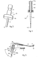
- the exact configuration of the diagnostic probe 10 can the perspective view in Fig. 3 be removed. It is a probe for examining interdental spaces.
- An essential element of the probe 10 is an elongated light wedge 11 made of a transparent material, at the lower end of which the excitation radiation A is coupled out and directed onto the tooth region to be examined.
- plastic or sapphire can be used as the material for the light wedge 11, wherein plastic is advantageous in terms of the lower risk of breakage and production costs, but has disadvantages in terms of wear and the resulting lifetime.
- the light is to be coupled laterally to the longitudinal axis of the light wedge 11 to allow an examination of the interdental spaces.
- the front end of the consisting of a transparent material light wedge 11 is provided with a slope 13 which forms an angle ⁇ of about 40 to 45 ° with the longitudinal axis of the light wedge.
- the incident light from above is then totally reflected at this slope 13 and laterally decoupled from the light wedge 11.
- the slope 13 could also be mirrored to achieve the deflection of the light.
- the return transmission of the radiation of radiation F produced on the surface of the tooth towards radiation takes place in a similar manner in the reverse direction.
- the response radiation falls laterally into the light wedge 11 and in turn is reflected at the slope 13 and thus directed to the end face of the probe 10 and coupled into the fiber rod 30.
- the fiber rod 30 which in turn preferably consists of a plurality of individual fibers with a diameter of 0.1 mm and a total diameter of about 1.4 mm, then the response radiation is coupled into a light fiber bundle 31, which on the one hand consists of the or the excitation radiation fiber (s) 23 for the excitation radiation A and on the other hand from a detection fiber 41 for transmitting the response radiation F.
- the detection fiber 41 which preferably has a diameter of 0.25 mm, then the forwarding to a detection device 40, whose detailed structure will be described later.
- the task of this detection device 40 is to detect the response radiation reflected back from the tooth surface, to analyze it and to judge on the basis of the measurement result whether or not one of the aforementioned fluorescing substances is present on the examined tooth surface.
- the diagnostic probe 10 is to be noted that it is rotatably mounted in the head portion 3 of the handpiece 1 by 360 °, so that the handpiece 1 can be very flexibly brought to the teeth to be examined.
- the probe 10 is latched to the head portion 3 of the handpiece 3 and can in a very simple manner -. for cleaning purposes or for replacement by another probe.
- a cylindrical guide 8 for the probe 10 and a locking pin 6 are provided in the head portion 3 of the handpiece 1, which presses with the aid of a spring 7 against the probe 10 and thus holds it in the inserted position within the guide 8.
- the front ball segment of the locking pin 6 engages in a circumferential recess 14 of a holder 12 for the light wedge 11, so that the probe 10 is always pressed to stop and safely within the handpiece 1 but at the same time rotatably mounted.
- a rotation of the probe 12 by hand is facilitated by a disc or annular attachment 12a on the holder 12, which can be easily grasped and twisted by a user of the handpiece 1 with his fingers.
- the holder 12 itself has an elongated bore, in which the light wedge 11 is inserted, with the possibility exists to replace the light wedge 11.
- a defined arrangement or orientation of the light wedge 11 within the holder 12 is ensured by a nose 11 a, which cooperates with a corresponding recess in the holder 12.
- the diagnostic probe 10 is not held at a right angle relative to the handpiece longitudinal axis, but preferably slightly obliquely at an angle ⁇ of approximately 80 °. It has been found that this results in a particularly ergonomically favorable handling of the examination device according to the invention.
- the detachable mounting of the probe 10 has the advantage that the probe 10 can be removed after each examination and cleaned and disinfected separately from the other components of the handpiece 1. On the other hand, however, there is also the advantage that the probe 10 can be easily replaced and replaced by a differently shaped probe. This makes it possible to provide differently shaped probes, which can be designed according to the location or surface design of the tooth site to be examined.
- the 4 and 5 show by way of example two further probes used in the diagnostic system according to the invention.
- the probe 110 shown is a so-called Parosonde, which is intended for the examination of periodontal pockets and in particular for the localization of subgingival concretions on tooth roots.
- the probe 210 does not have a chamfer on the probe tip, but is merely flattened at its outermost end. As a result, a very slim light emission is achieved with a small diameter, so that the excitation radiation can be very concentrated directed to a point to be examined. A light emission on the circumference of the probe 110, however, is not provided.
- the parison 110 thus again consists of an elongated wedge 111 of a light-conducting material with a front light exit tip 113, wherein the light wedge 111 is held by a holder 112 with a disc-shaped attachment 112a, which in the rear area again the circumferential recess 114, via the one Locking is achieved with the handpiece has.
- a third probe 210 for carrying out investigations in the area of the fissure - that is to say for examining the occlusal surfaces of teeth or of smooth surfaces or tooth outer surfaces - is disclosed in US Pat Fig. 5 shown.
- the central element of this third probe 210 is a cylindrical light rod 211, which has in its front end region a frusto-conical end 213, is emitted via the light in the longitudinal direction of the probe 210 and coupled in the reverse direction.
- This third probe 210 also has the recess 214 required for detachable latching with the handpiece 1 and the holder 212 with the disk-shaped attachment 212a. It should be noted, however, that the probes of the 4 and 5 the rotation is not necessarily required, since a light exit or light entry always takes place in the direction of the longitudinal axis of the probe 110 and 210 anyway.
- the transmission of the excitation and response radiation A and F in the front end portion of the handpiece 1 by means of a curved fiber rod 30, at the handpiece end, the various optical fiber bundles 23 and 41 for the excitation radiation and the response radiation was followed.
- this fiber rod 30 it is also possible to dispense with this fiber rod 30 and instead combine the two bundles 23 for the excitation radiation and 41 for the response radiation to a common fiber bundle 31, which extends to the front of the probe 10 and directly light in this coupled or light from this decoupled.
- the common fiber bundle 31 thus consists on the one hand of fibers for the transmission of the excitation radiation A and on the other of fibers for the transmission of the response radiation F.
- a light guide 41 opens into a device 40 for detecting the response radiation, whose detailed embodiment now based on Fig. 7 should be explained.
- the central element of the detection unit 40 is a photodiode 42, which detects the response radiation F and converts it into an electrical signal in accordance with the intensity of the response radiation F.
- the level of the intensity of the response radiation F finally provides information as to whether fluorescing materials are present or not at the tooth tissue region investigated.
- the photodiode 42 is integrated into a housing 43 which is arranged as a whole in the handpiece 1. A laterally protruding from the housing 43 pin 44 is used for locking on a circuit board within the handpiece first
- the front end of the housing 43 is provided with a cylindrical opening 45 into which the optical fiber bundle is inserted. Through the opening 45, the bundle is held so that the light is directed to the photodiode 42 directly.
- a snap closure is provided at the opening 45, through which the fiber bundle 41 is also held firmly in the desired position.
- a filter 46 is integrated into the housing 43, which filters out the wavelength ranges which are not relevant for the evaluation of the response radiation F.
- the filter 46 is designed, for example, such that only radiation with wavelengths above 680 nm is transmitted. In the Fig. 7 shown arrangement is thus not only extremely compact but also ensures the most effective and accurate evaluation of the response radiation F.
- the 8 and 9 show in addition to the Figures 2a-c and 7 two further variants for the transmission of excitation and response radiation. It is in accordance with the variant Fig. 8 in turn initially provided a fiber bundle 31, which is provided both for the transmission of the excitation and the response radiation. However, the fiber bundle 31 is then not split into two separate bundles for the different radiations, but is directed with its rear end to a splitter mirror 32 or beam splitter, which is partially transparent and responsible for the coupling and decoupling of the excitation and response radiation.
- the divider mirror 32 which is inclined relative to the optical axis of the rearward end of the fiber bundle 31, consists of a material which, on the one hand, reflects the excitation radiation A originating from the photodiode 20 and, on the other hand, allows the response radiation F, which is of interest, to pass unimpeded in the direction of the detection unit 40.
- the positions of the photodiode 20 and the detection unit 40 can also be exchanged, provided that the splitter mirror 32 is correspondingly coated, that is to say that it is suitably permeable or reflective for the corresponding wavelengths.
- a common fiber bundle for transmitting the radiation is completely dispensed with and, instead, the light of the excitation and response radiation is directed toward the probe or in the opposite direction with the aid of mirrors and lenses. That in the variant in Fig. 8 provided fiber bundle 31 is hereby replaced by a deflection mirror 33 in the head region of the handpiece 1, which deflects the light in a suitable manner. With the aid of a focusing lens 34, which is likewise arranged in the head region, it is ensured that the light also impinges on the various optical elements in the desired bundled manner. The coupling and decoupling of the excitation and response radiation is again carried out with the help of arranged in the rear region of the handpiece splitter 32nd
- the solution to this problem according to the invention is to provide the handpiece 1 with a sleeve which can be removed from the handpiece and sterilized separately, the sleeve itself being that part which comes into contact with the patient and contains as few electronic components as possible ,
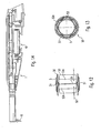
- This solution should be based on the Fig. 10 to 13 will now be explained in more detail.
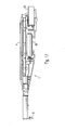
- Fig. 10 shows the handpiece with the already removed sleeve 50, which in the removed state in Fig. 11 is shown.
- the sleeve 50 completely surrounds the front end region of the handpiece 1, so that it is ensured that only the sleeve 50 comes into contact with the patient, but not the internal components of the examination device.
- the sleeve 50 can then be withdrawn from the front or pushed onto the handpiece body 2, with the aid of a detent pin 50a at the rear end of the sleeve 50 a secure hold between the sleeve 50 and handpiece body 2 is achieved.
- the hold between the two elements is further enhanced by an O-ring 50b which is disposed in the central region of the handpiece body 2 and also provides a seal for the rear handpiece area.
- the sleeve 50 is made of a material which is easy to clean and sterilize. Further, the essential electronic components of the handpiece 1 according to the invention - as already mentioned - not in the sleeve 50 but in the remaining portion of the handpiece 1 is arranged, which need not be sterilized.
- a ring switch 5 is provided which can be actuated even when the sleeve 50 is attached and, despite everything, is not damaged by the sterilization process.
- the inventive design of the ring switch is in the FIGS. 12 and 13 shown in more detail.
- the switch consists of two components, which are arranged on one side or in the sleeve 50 and the other in the interior of the handpiece.
- An essential part of the switch in the interior of the handpiece 1 is an electrical line 52 which is interrupted at the location of the ring switch.
- the lines end here in each case on a cylindrical plastic sleeve 53, the two spaced-apart circumferential tracks 53a (which also in Fig. 10 are shown), which are separated by a gap 53b.
- a plurality of plate-shaped contacts 51 are provided in the sleeve 50, which are components of a switching cap in the form of a flexible ring 5, which is part of the sleeve 50 and is arranged in the mounted state of the sleeve 50 on the handpiece 1 in the region of the tracks 53a.
- Essential in the embodiment according to the invention is that only the contacting elements 51 must be sterilized together with the sleeve 50.
- these may consist of a material which is relatively insensitive to the high temperatures of a hot air sterilization, so that thus a switching element for activating the examination device is obtained, which is well sterilized despite everything.
- the other components of the switch and the examination device as a whole do not need to be sterilized, so that damage to them is avoided.
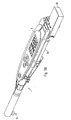
- the Fig. 14 and 15 show the handpiece according to the invention in a lateral or perspective view in partial section.
- a battery receptacle for supplying power to the examination device according to the invention is provided in the rear region of the handpiece body.
- a control and display panel 4 At the upper end of the rear portion of the handpiece body 2 is also a control and display panel 4, which will be explained later.
- the handpiece 1 also has a loudspeaker, over which the current measurement result can be displayed acoustically.
- the intensity of the measured response radiation could hereby be represented by a signal which changes in frequency and / or volume.
- the receptacle for the battery 60 or batteries for power supply is designed so that accidental wrong insertion of the batteries 60 is prevented.
- This reverse polarity protection is in Fig. 16 and has as an essential element in the region which is provided for contacting the positive pole 60 a of the battery 60, a contact surface 63 which includes a circular recess 64.
- the positive pole 60a can pass through this recess 64 and contact the terminal 61. If, on the other hand, the battery 60 were used in the opposite direction, no contact would be made, since the negative terminal 60b of the battery 60 can not reach through the opening 64 of the contact surface 63. The damage to the device by incorrect insertion of the batteries 60 in the handpiece 1 is thus excluded.
- an essential feature of the handpiece 1 according to the invention is that it can be used completely independently of external devices. All elements necessary for carrying out the examination and presentation of the examination result are arranged inside the handpiece 1. In particular, the representation of the measurement result, as will be explained in more detail later, also takes place via the handpiece 1 itself.
- a communication module 65 via which the measurement data can be transmitted wirelessly to an external unit.
- the module 65 can be provided in particular to transmit the measured data as radio data, which has the advantage that a high transmission quality is ensured and thus the risk of incorrect transmission is almost impossible.
- a particular advantage of the transmission of the data by means of ultrasound is that the loudspeaker provided on the handpiece 1, which is primarily used to display the measurement results, can also be used for data transmission at the same time. This means that can be dispensed with an additional element for data transmission and only a suitable control of the speaker must be ensured.
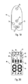
- FIGS. 19 and 20 show the located at the top of the handpiece control panel 4a for the activation of certain functions and the display unit 4b for displaying the current function or the measurement result, while on the other hand Fig. 21 schematically illustrates the concept of operator guidance for the handpiece 1 according to the invention.
- the control panel 4a consists of a total of five keys, namely a central key 70, a memory key 71, a menu key 72 and two dial keys 73 and 74. The function of each key is later based on the operating scheme of Fig. 21 explained.
- the display panel 4b has on the one hand a first digital display 75 for displaying the current measured value, a second display 76 for displaying the maximum value and a display 77 for displaying the number of the probe used. Furthermore, six light symbols 78 to 83 are provided, by which the status in which the handpiece 1 is currently located, or an action being performed is displayed.
- the handpiece can be fully switched on and off; moreover, the maximum value can be reset or an offset correction can be carried out.
- the function of the memory button 71 depends on whether the menu mode is currently active or not. In the event that the menu has just not been activated, the transmission of the current peak value via the wireless connection to a central processing unit is initiated by pressing the memory button 71, which is illustrated by the illumination of the light symbol 83. If, on the other hand, the handpiece 1 is currently in a certain menu item, then it is determined by the Press the memory button 71 to save the currently set value and exit the menu.
- the function of the two dial keys 73 and 74 also depends on whether the menu is currently active or not.
- a signal can be transmitted via the wireless connection to a central display unit, which causes a forward movement in a tooth diagram shown on a display.
- a backward movement in the tooth scheme is initiated by means of the key 74, so keys 73 and 74 at this stage are used as navigation keys.
- the current numerical value of the parameter to be set in the corresponding menu item can be increased or decreased with the keys 73 and 74.
- menu key 72 is used to call up a particular menu item, with a rotating selection between the various items.
- the different menu items are adjustment, probe selection, volume, reference value and display mode, whereby the different functions of these menu items correspond to the scheme in Fig. 21 can be removed.
- the menu item " Adjustment” serves to carry out a comparison of the examination device. After pressing the memory button 71, a zero signal is first recorded for this purpose, which is obtained by directing the measuring probe into free space. Subsequently, the probe is to be directed to a reference body and it is carried out a further measurement, wherein the measurement result obtained in this case is used to equalize the examination device.
- Probe selection can be used to assign a specific number to the currently mounted probe. This is helpful in a later evaluation of the measurement result, since each measurement result is assigned a specific probe.
- the third menu item " Volume” is used to adjust the volume of the measuring signal sent via the loudspeaker.
- reference value it is possible to determine a reference value indicating from which intensity of the measuring signal on the presence of caries is concluded or an acoustic indication of the measurement result takes place.
- the device according to the invention is in the so-called display mode.
- This is in the instantaneous value display 75 at a Activation of the light source for the excitation radiation of the instantaneous measured value shown, which gives information about the intensity of the detected response radiation.
- the peak value display 76 shows the peak value of the current measurement, which is determined by a permanent comparison with the current measured values. The storage of this peak value is advantageous because at a later time of the measurement it is easy to find again the point at which the largest accumulation of a fluorescent substance was diagnosed.
- the user scheme according to the invention is particularly catchy and understandable, since it is a uniform operating scheme for each individual menu item.
- the operation of the examination device according to the invention can thus be carried out by non-experienced persons after a short time.
- an examination device for the examination of tooth surfaces is specified by the present invention, which is characterized by its particularly simple handling, but at the same time also meets the requirements for a sufficient hygiene.
Landscapes
- Health & Medical Sciences (AREA)
- Life Sciences & Earth Sciences (AREA)
- Heart & Thoracic Surgery (AREA)
- Medical Informatics (AREA)
- Physics & Mathematics (AREA)
- Veterinary Medicine (AREA)
- Biophysics (AREA)
- Pathology (AREA)
- Engineering & Computer Science (AREA)
- Biomedical Technology (AREA)
- Public Health (AREA)
- General Health & Medical Sciences (AREA)
- Molecular Biology (AREA)
- Surgery (AREA)
- Animal Behavior & Ethology (AREA)
- Oral & Maxillofacial Surgery (AREA)
- Audiology, Speech & Language Pathology (AREA)
- Dentistry (AREA)
- Dental Tools And Instruments Or Auxiliary Dental Instruments (AREA)
- Investigating, Analyzing Materials By Fluorescence Or Luminescence (AREA)
- Investigating Or Analysing Materials By Optical Means (AREA)
Description
Die vorliegende Erfindung betrifft eine zahnärztliche Vorrichtung zum Untersuchen der optischen Eigenschaften von Zahngewebe gemäß dem Oberbegriff des Anspruchs 1. Insbesondere betrifft die vorliegende Erfindung eine Vorrichtung zum Erkennen von fluoreszierenden Substanzen an Zähnen, beispielsweise von Karies, Plaque, bakteriellem Befall, Konkrementen oder Zahnstein.The present invention relates to a dental device for examining the optical properties of tooth tissue according to the preamble of
In der Dentaldiagnostik sind optische Untersuchungsvorrichtungen, mit deren Hilfe beispielsweise Karies, Plaque, bakterieller Befall, Konkremente oder Zahnstein erkannt werden kann, bereits seit längerem und in unterschiedlichen Varianten bekannt. Allen bekannten Vorrichtungen ist gemeinsam, dass ein zu untersuchender Zahngewebebereich zunächst mit einer Anregungsstrahlung bestrahlt wird, woraufhin von dem Zahn eine Antwortstrahlung abgegeben wird. Diese Antwortstrahlung kann sowohl die zurückreflektierte Strahlung gleicher Wellenlänge als auch eine Fluoreszenzstrahlung beinhalten. Die Antwortstrahlung wird wiederum erfaßt und einer Auswerteeinheit zugeführt, welche anhand des Spektrums der Antwortstrahlung ermittelt, ob eine der oben genannten Substanzen vorhanden ist oder nicht. Die bekannten optischen Diagnoseverfahren und Vorrichtungen unterscheiden sich dabei durch die verwendete(n) Wellenlänge(n) für die Anregungsstrahlung sowie durch die Auswertung der erfaßten Antwortstrahlung. Eine erste Möglichkeit besteht darin, zu untersuchen, ob an dem Zahn eine Fluoreszenzstrahlung als Reaktion auf die Anregungsstrahlung hin entstanden ist. Eine andere Möglichkeit besteht bei der sogenannten Reflexionsspektrometrie darin, zu untersuchen, welche Wellenlängen von der Zahnoberfläche in welcher Weise reflektiert werden.In dental diagnostics, optical examination devices with the aid of which, for example, caries, plaque, bacterial infestation, concrements or tartar can be recognized, have been known for some time and in different variants. All known devices have in common that a tooth tissue region to be examined is first irradiated with an excitation radiation, whereupon a response radiation is emitted by the tooth. This response radiation may include both the reflected back radiation of the same wavelength and fluorescence radiation. The response radiation is again detected and fed to an evaluation unit, which determines based on the spectrum of the response radiation, whether one of the above substances is present or not. The known optical diagnostic methods and devices differ in this case by the wavelength (s) used for the excitation radiation and by the evaluation of the detected response radiation. A first possibility is to investigate whether fluorescence radiation has arisen on the tooth in response to the excitation radiation. Another possibility exists in the so-called reflection spectrometry to investigate which wavelengths are reflected by the tooth surface in which way.
Vorrichtungen dieser Art sind beispielsweise in der
Aus der
Aus der
Aus der
Aus der
Der vorliegenden Erfindung liegt die Aufgabenstellung zugrunde, die Handhabung bislang bekannter zahnärztlicher optischer Untersuchungseinrichtungen weiter zu verbessern. Hierbei ist zu berücksichtigen, dass für einen Benutzer des Geräts die Möglichkeit bestehen sollte, auch schwer zugängliche Bereiche innerhalb des Mundraums eines Patienten untersuchen zu können. Ferner sollte die Möglichkeit einer einfachen Reinigung bestehen, da insbesondere diejenigen Teile, welche in den Mundraum des Patienten gelangen, auch sterilisiert werden müssen. Die Aufgabenstellung wird durch die in dem unabhängigen Ansprüch 1 definierte Erfindung gelöst.The present invention is based on the object to further improve the handling of previously known dental optical examination devices. It should be noted that it should be possible for a user of the device to examine even inaccessible areas within the oral cavity of a patient. Furthermore, there should be the possibility of simple cleaning, since in particular those parts which enter the oral cavity of the patient must also be sterilized. The problem is solved by the invention defined in the
Dabei wird gemäß der vorliegenden Erfindung vorgeschlagen, die zahnärztliche Untersuchungsvorrichtung derart auszugestalten, dass sie durch ein Handgerät gebildet ist, welches im Prinzip vollkommen unabhängig von weiteren Einrichtungen benutzt werden kann und alle wesentlichen und zur Durchführung des optischen Diagnoseverfahrens erforderlichen Elemente aufweist.It is proposed according to the present invention, the dental examination device to design such that it is formed by a hand-held device, which can be used in principle completely independent of other facilities and has all the essential and necessary for performing the optical diagnostic method elements.
Durch die Ausgestaltung der optischen Untersuchungsvorrichtung als autonom arbeitendes Handstück ist der Benutzer der Vorrichtung nicht mehr in seinem Bewegungsspielraum eingeschränkt. Die Handhabung der Vorrichtung ist somit im Vergleich zu den bekannten Vorrichtungen, bei denen das Handstück über einen Versorgungsschlauch mit einer Konsole verbunden ist, deutlich verbessert.Due to the configuration of the optical examination device as an autonomously operating handpiece, the user of the device is no longer restricted in his range of motion. The handling of the device is thus in Compared to the known devices in which the handpiece is connected via a supply hose to a console, significantly improved.
Gemäß einer vorteilhaften Weiterbildung dieses Erfindungsgedankens kann vorgesehen sein, dass die von der Untersuchungsvorrichtung erstellten Meßergebnisse zur Ergänzung oder Weiterverarbeitung drahtlos an eine externe Darstellungs- und/oder Auswerteeinheit übermittelt werden. Bei dieser externen Einheit kann es sich beispielsweise um einen PC innerhalb einer zahnärztlichen Praxis handeln, in dem automatisch die während der Untersuchung erstellten Meßergebnisse abgelegt und dem entsprechenden Patienten zugeordnet werden. Ferner kann diese externe Einheit zur zusätzlichen Darstellung des Meßergebnisses - beispielsweise anhand eines Zahnschemas - verwendet werden. Die Übermittlung der Signale kann dabei in Form elektromagnetischer Signale, mittels Ultraschall oder anderer bekannter drahtloser Übertragungstechniken erfolgen.According to an advantageous development of this inventive concept it can be provided that the measurement results produced by the examination device for the purpose of supplementing or further processing are transmitted wirelessly to an external presentation and / or evaluation unit. This external unit may be, for example, a PC within a dental practice in which the measurement results created during the examination are automatically stored and assigned to the corresponding patient. Furthermore, this external unit for additional representation of the measurement result - for example, using a dental chart - are used. The transmission of the signals can take place in the form of electromagnetic signals, by means of ultrasound or other known wireless transmission techniques.
Die vorliegende Erfindung befaßt sich weiterhin mit der Problematik der Reinigung bzw. Sterilisierung der Untersuchungsvorrichtung. Wie bereits oben erwähnt wurde, sollte eine einfache Reinigung möglich sein, da in zahnärztlichen Praxen hohe Hygieneanforderungen bestehen. Da zumindest der vordere Teil der Untersuchungsvorrichtung in den Mundraum des Patienten gelangt, sollte insbesondere die Möglichkeit bestehen, diesen Bereich zu sterilisieren.The present invention further deals with the problem of cleaning or sterilization of the examination device. As already mentioned above, a simple cleaning should be possible, since there are high hygiene requirements in dental practices. Since at least the front part of the examination device enters the oral cavity of the patient, there should in particular be the possibility of sterilizing this area.
Gemäß der vorliegenden Erfindung wird deshalb vorgeschlagen, das Handstück, in dem die Elemente der optischen Untersuchungsvorrichtung angeordnet sind, zumindest in seinem vorderen Bereich mit einer Hülse zu versehen, welche abnehmbar ist und aus einem sterilisierbarem Material besteht. Da bei dieser Lösung lediglich die Hülse sowie die zur Übermittlung der Anregungs- und Antwortstrahlung erforderliche Untersuchungssonde in Kontakt mit dem Patienten gelangen, können nach einer Untersuchung die Sonde und die Hülse von dem Handstück abgenommen und getrennt sterilisiert werden, wobei insbesondere die zur Ansteuerung der Lichtquelle und Auswertung der Antwortstrahlung erforderlichen elektronischen Komponenten der Vorrichtung in dem nicht zu reinigenden Bereich des Handstücks verbleiben und damit nicht belastet werden.According to the present invention, it is therefore proposed to provide the handpiece in which the elements of the optical inspection device are arranged, at least in its front region with a sleeve which is removable and consists of a sterilizable material. Since in this solution only the sleeve and the examination probe required for the transmission of the excitation and radiation radiation come into contact with the patient, the probe and the sleeve can be removed from the handpiece and sterilized separately after an examination, in particular those for controlling the light source and evaluation of the response radiation required electronic components of the device remain in the non-clean area of the handpiece and are therefore not burdened.
Entsprechend der Erfindung weist die Hülse Teile eines Schaltelements zum Aktivieren der Vorrichtung bzw. der Mittel zum Erzeugen der Anregungsstrahlung auf. Insbesondere handelt es sich bei dem Schaltelement um einen Ringschalter, der eine im Inneren des Handstücks verlaufende elektrische Leitung aufweist, welche im Bereich des Ringschalters unterbrochen ist. Die abnehmbare Hülse weist im Bereich der Unterbrechung ein betätigbares Element mit einem aus einem leitfähigen Material bestehenden Überbrückungselement auf, über welches die Leitung geschlossen und damit das Handstück bzw. die Mittel zur Erzeugung der Anregungsstrahlung aktiviert werden können. Vorzugsweise handelt es sich bei dem betätigbaren Element um eine aus einem flexiblen Material bestehende Schaltkappe.According to the invention, the sleeve has parts of a switching element for activating the device or the means for generating the excitation radiation. In particular, the switching element is a ring switch which has an electrical line extending in the interior of the handpiece, which is in the region of Ring switch is interrupted. In the region of the interruption, the removable sleeve has an actuatable element with a bridging element made of a conductive material, via which the line can be closed and thus the handpiece or the means for generating the excitation radiation can be activated. Preferably, the actuatable element is a switching cap made of a flexible material.
Die abnehmbare Hülse ist vorzugsweise von der Vorderseite her auf das Handstück aufsetzbar, wobei insbesondere vorgesehen sein kann, dass die Hülse nur dann aufgeschoben bzw. abgenommen werden kann, wenn die zur Übermittlung der Anregungs- und Antwortstrahlung vorgesehene Diagnosesonde von dem Handstück abgenommen ist. Auch diese Sonde ist vorzugsweise an dem vorderen Handstückende lösbar befestigt, insbesondere verrastet und kann drehbar gelagert sein. Dabei kann ferner auch vorgesehen sein, unterschiedlich gestaltete Diagnosesonden bereitzustellen, welche das Licht der Anregungs- und Antwortstrahlung entsprechend dem Bereich, der gerade untersucht werden soll, in jeweils bestimmter Weise ein- und auskoppeln. Hierdurch wird die Möglichkeit eröffnet, die erfindungsgemäße Untersuchungsvorrichtung z.B. sowohl zur Untersuchung von Kauflächen als auch zur Untersuchung in Zahnfleischtaschen und Zahnzwischenräumen zu verwenden.The removable sleeve is preferably placed on the handpiece from the front, wherein it can be provided in particular that the sleeve can be pushed or removed only when the intended for the transmission of excitation and response radiation diagnostic probe is removed from the handpiece. This probe is also preferably releasably attached to the front handpiece end, in particular latched and can be rotatably mounted. In this case, it can also be provided to provide differently designed diagnostic probes, which couple the light of the excitation and response radiation according to the area that is currently being investigated in each case in a certain way and decoupled. This opens up the possibility of the examination device according to the invention, e.g. both for examining occlusal surfaces and for examination in periodontal pockets and interdental spaces.
Ein weiterhin Aspekt befaßt sich mit der Problematik, die zur Erfassung der von der Zahnoberfläche zurückgeworfenen Antwortstrahlung erforderlichen Elemente möglichst kompakt zu gestalten, so dass diese platzsparend in das Handstück integriert werden können.A further aspect is concerned with the problem of making the elements required for detecting the response radiation reflected by the tooth surface as compact as possible so that they can be integrated into the handpiece to save space.
Dabei ist vorgesehen, eine zum Erfassen der Antwortstrahlung vorgesehene Fotodiode innerhalb eines kleinen Gehäuses anzuordnen, welches in das Handstück eingesetzt ist. Die Übermittlung der Antwortstrahlung zu der Fotodiode erfolgt dabei über einen Lichtleiter, an dessen einem Ende die Fotodiode angeordnet ist. Um eine optimale Einkopplung des von dem Lichtleiter übertragenen Lichts in die Fotodiode zu ermöglichen, kann dabei das Gehäuse eine Öffnung aufweisen, in welche der Lichtleiter mündet, wobei an dem Gehäuse insbesondere ein Schnappverschluß zum Befestigen des Lichtleiters angeordnet sein kann. Vorzugsweise ist innerhalb des Gehäuses noch ein zwischen dem Lichtleiterende und der Fotodiode angeordnetes Filter vorgesehen, welches nur die zur Auswertung der Antwortstrahlung erforderlichen Wellenlängen durchläßt. Diese kompakte Anordnung ermöglicht eine sehr effektive Auswertung der auf die Bestrahlung mit der Anregungsstrahlung hin entstehenden Antwortstrahlung, wobei gleichzeitig eine weitgehende Miniaturisierung erzielt wird.It is provided to arrange a provided for detecting the response radiation photodiode within a small housing which is inserted into the handpiece. The transmission of the response radiation to the photodiode is effected via a light guide, at one end of which the photodiode is arranged. In order to enable optimum coupling of the light transmitted from the light guide into the photodiode, the housing can have an opening into which the light guide opens, wherein in particular a snap-action closure for fastening the light guide can be arranged on the housing. Preferably, a filter arranged between the optical waveguide end and the photodiode is provided within the housing, which transmits only the wavelengths required for evaluating the response radiation. This compact arrangement allows a very effective evaluation of the response radiation resulting from the irradiation with the excitation radiation, at the same time achieving a substantial miniaturization.
Andere Weiterbildungen und vorteilhafte Ausgestaltungen der erfindungsgemäßen Vorrichtung sind Gegenstand der Unteransprüche. Sie werden im Zusammenhang mit der Beschreibung mehrerer Ausführungsbeispiele der vorliegenden Erfindung anhand der beiliegenden Zeichnungen näher erläutert. Dabei zeigen:
- Fig. 1
- eine erfindungsgemäße zahnärztliche optische Untersuchungsvorrichtung in Form eines Handstücks;
- Fig. 2a
- die Ausgestaltung und Anordnung der wesentlichen Komponenten zur optischen Kariesdiagnose;
- Fig. 2b und 2c
- vergrößerte Darstellungen von
Fig. 2a ; - Fig. 3
- eine vergrößerte Darstellung eines ersten Ausführungsbeispiels einer Diagnosesonde zum Übermitteln der Anregungs- und Antwortstrahlung;
- Fig. 4
- eine zweite Variante einer Diagnosesonde im Schnitt;
- Fig. 5
- eine dritte Variante einer Diagnosesonde;
- Fig. 6
- ein Schema zur Übermittlung der Anregungs- und Antwortstrahlung gemäß einem ersten Ausführungsbeispiel;
- Fig. 7
- eine Darstellung einer erfindungsgemäßen Anordnung und Ausgestaltung der zur Auswertung der Antwortstrahlung vorgesehenen Fotodiode;
- Fig. 8 und 9
- zwei weitere Möglichkeiten zur Übermittlung der Anregungs- und Antwortstrahlung;
- Fig. 10
- das Handstück bei abgenommener Hülse;
- Fig. 11
- die von dem Handstück abnehmbare Hülse;
- Fig. 12
und 13 - eine Möglichkeit zur Realisierung eines einfach zu reinigenden Schaltelements zur Aktivierung der Anregungsstrahlung;
- Fig. 14
- die erfindungsgemäße Untersuchungsvorrichtung im Teilschnitt;
- Fig. 15
- die Untersuchungsvorrichtung in einer weiteren perspektivischen Darstellung;
- Fig. 16
- die Anordnung einer zur Stromversorgung der Vorrichtung vorgesehenen Batterie innerhalb des Handstücks;
- Fig. 17 und 18
- zwei Darstellungen einer erweiterten Variante der erfindungsgemäßen Vorrichtung, bei der zusätzlich ein Funkmodul zur drahtlosen Übertragung der Meßdaten vorgesehen ist;
- Fig. 19
- das an dem Handstück vorgesehene Bedienfeld zur Aktivierung bzw. Einstellung der unterschiedlichen Funktionen;
- Fig. 20
- die an dem Handstück vorgesehene Anzeige zur Darstellung der Funktionen und Meßergebnisse und
- Fig. 21
- das Bedien- und Benutzungsschema der erfindungsgemäßen Untersuchungsvorrichtung.
- Fig. 1
- a dental optical examination device according to the invention in the form of a handpiece;
- Fig. 2a
- the design and arrangement of the essential components for the optical caries diagnosis;
- Fig. 2b and 2c
- enlarged representations of
Fig. 2a ; - Fig. 3
- an enlarged view of a first embodiment of a diagnostic probe for transmitting the excitation and response radiation;
- Fig. 4
- a second variant of a diagnostic probe in section;
- Fig. 5
- a third variant of a diagnostic probe;
- Fig. 6
- a scheme for transmitting the excitation and response radiation according to a first embodiment;
- Fig. 7
- a representation of an arrangement according to the invention and embodiment of the provided for evaluating the response radiation photodiode;
- 8 and 9
- two other ways to transmit the excitation and response radiation;
- Fig. 10
- the handpiece with removed sleeve;
- Fig. 11
- the detachable from the handpiece sleeve;
- FIGS. 12 and 13
- a possibility for the realization of an easy-to-clean switching element for activating the excitation radiation;
- Fig. 14
- the examination device according to the invention in partial section;
- Fig. 15
- the examination device in a further perspective view;
- Fig. 16
- the arrangement of provided for powering the device battery within the handpiece;
- FIGS. 17 and 18
- two representations of an expanded variant of the device according to the invention, in which a radio module for wireless transmission of the measured data is additionally provided;
- Fig. 19
- the control panel provided on the handpiece for activating or adjusting the various functions;
- Fig. 20
- provided on the handpiece display for displaying the functions and measurement results and
- Fig. 21
- the operating and use scheme of the examination device according to the invention.
Im vorderen Bereich 3 des Handstücks 1 ist ferner ein Ringschalter 5 vorgesehen, der zum Aktivieren der Anregungsstrahlungsquelle verwendet werden kann. Wie ebenfalls später noch ausführlicher erläutert wird, ist dieser Ringschalter 5 Bestandteil einer von dem Handstück 1 zur Vorderseite hin abnehmbaren Hülse, wodurch ein einfaches Reinigen und Sterilisieren derjenigen Teile des Handstücks 1, die mit dem Patienten in Kontakt gelangen, ermöglicht wird.In the
Die
Bei dem dargestellten Handstück 1 wird die Lichtquelle zur Erzeugung der Anregungsstrahlung durch eine Laserdiode 20 gebildet, welche ein nahezu monochromatisches Licht erzeugt. Insbesondere kann die Anregungsstrahlung im Bereich zwischen 600 nm und 670 nm, vorzugsweise bei ca. 655 nm liegen, da bei einer derartigen Wellenlänge der bestmögliche Kompromiß zwischen der Ausgangsleistung der Laserdiode 20 und dem spektralen Unterschied zwischen der Anregungsstrahlung und der von der Zahnoberfläche zurückgeworfenen Antwortstrahlung erzielbar ist. Anzumerken ist, dass die Funktion des erfindungsgemäßen Handstücks hier am Beispiel einer Fluoreszenzdiagnose erläutert wird, bei der die an der Zahnoberfläche als Reaktion auf die Bestrahlung hin entstehende Fluoreszenzstrahlung bewertet wird. Alternativ dazu bestünde allerdings auch die Möglichkeit, andere Wellenlängen für die Anregungs- und/oder Antwortstrahlung zu verwenden oder im Rahmen einer sog. Reflexionsspektrometrie zur untersuchen, welche Wellenlängen von der Zahnoberfläche in welcher Weise reflektiert werden.In the illustrated
Mit Hilfe einer der Laserdiode 20 vorgeschalteten Linse 21 sowie einem optischen Filter 22, der das von der Laserdiode 20 abgegebene Licht nochmals auf den gewünschten Wellenlängenbereich eingrenzt, wird dann eine Anregungsstrahlung A erzeugt und in einen ersten Lichtleiter 23 eingekoppelt. Bei diesem Lichtleiter 23 kann es sich um eine einzelne Lichtfaser mit einem Durchmesser von ca. 0,5 mm handeln, es bestünde allerdings auch die Möglichkeit, den Lichtleiter 23 aus einer Vielzahl von einzelnen Lichtleiterfasern zu bilden. An seinem vorderen Ende grenzt der Lichtleiter 23 an einen gekrümmten Faserstab 30 aus einem ebenfalls lichtleitenden Material an, durch den die Anregungsstrahlung umgelenkt und in die Stirnseite der Diagnosesonde 10 eingekoppelt wird.By means of a
Die genaue Ausgestaltung der Diagnosesonde 10 kann der perspektivischen Darstellung in
Wie insbesondere der Darstellung in
Die Rückübermittlung der auf die Bestrahlung hin an der Zahnoberfläche entstehenden Antwortstrahlung F erfolgt in ähnlicher Weise in umgekehrter Richtung. Zunächst fällt die Antwortstrahlung seitlich in den Lichtkeil 11 ein und wird wiederum an der Schräge 13 reflektiert und somit zur Stirnseite der Sonde 10 gelenkt und in den Faserstab 30 eingekoppelt. Von dem Ende des Faserstabs 30, der wiederum vorzugsweise aus einer Vielzahl von Einzelfasern mit einem Durchmesser von 0,1 mm besteht und insgesamt einen Durchmesser von ca. 1,4 mm aufweist, wird dann die Antwortstrahlung in ein Lichtfaserbündel 31 eingekoppelt, welches zum einen aus der bzw. den Anregungsstrahlungsfaser(n) 23 für die Anregungsstrahlung A und zum anderen aus einer Detektionsfaser 41 zur Übermittlung der Antwortstrahlung F besteht.The return transmission of the radiation of radiation F produced on the surface of the tooth towards radiation takes place in a similar manner in the reverse direction. First, the response radiation falls laterally into the
Über die Detektionsfaser 41, die vorzugsweise einen Durchmesser von 0,25 mm aufweist, erfolgt dann die Weiterleitung zu einer Erfassungseinrichtung 40, deren näherer Aufbau später noch beschrieben wird. Die Aufgabe dieser Erfassungseinrichtung 40 ist es, die von der Zahnoberfläche zurückgestrahlte Antwortstrahlung zu erfassen, zu analysieren und auf Basis des Meßergebnisses zu beurteilen, ob eine der eingangs genannten fluoreszierenden Substanzen an der untersuchten Zahnoberfläche vorhanden ist oder nicht.About the
Zu der Diagnosesonde 10 ist zu anzumerken, dass diese in dem Kopfbereich 3 des Handstücks 1 um 360° drehbar gelagert ist, so dass das Handstück 1 sehr flexibel an die zu untersuchenden Zähne herangeführt werden kann. Die Sonde 10 ist dabei mit dem Kopfbereich 3 des Handstücks 3 verrastet und kann in sehr einfacher Weise - z.B. zu Reinigungszwecken oder zum Ersetzen durch eine andere Sonde - entnommen werden. Hierzu sind in dem Kopfbereich 3 des Handstücks 1 zunächst eine zylinderförmige Führung 8 für die Sonde 10 sowie ein Raststift 6 vorgesehen, der mit Hilfe einer Feder 7 gegen die Sonde 10 drückt und diese damit in der eingesetzten Position innerhalb des Führung 8 hält. Das vordere Kugelsegment des Raststifts 6 greift dabei in eine umlaufende Ausnehmung 14 eines Halters 12 für den Lichtkeil 11 ein, so dass die Sonde 10 immer auf Anschlag gedrückt wird und sicher innerhalb des Handstücks 1 aber zugleich drehbar gelagert ist. Eine Drehung der Sonde 12 von Hand wird dabei durch einen scheiben- oder ringförmigen Aufsatz 12a an dem Halter 12 erleichtert, der von einem Benutzer des Handstücks 1 mit den Fingern leicht gegriffen und verdreht werden kann. Der Halter 12 selbst weist eine längliche Bohrung auf, in welche der Lichtkeils 11 eingesetzt ist, wobei die Möglichkeit besteht, den Lichtkeil 11 auszuwechseln. Ein definierte Anordnung bzw. Orientierung des Lichtkeils 11 innerhalb des Halters 12 ist durch eine Nase 11a sichergestellt, welche mit einer entsprechenden Ausnehmung in dem Halter 12 zusammenwirkt.To the
Anzumerken ist ferner, dass die Diagnosesonde 10 gegenüber der Handstücklängsachse nicht in einem rechten Winkel, sondern vorzugsweise leicht schräg in einem Winkel β von ca. 80° gehalten wird. Es hat sich herausgestellt, dass hierdurch eine besonders ergonomisch günstige Handhabung der erfindungsgemäßen Untersuchungsvorrichtung erzielt wird.It should also be noted that the
Die lösbare Halterung der Sonde 10 bringt zum einen den Vorteil mit sich, dass die Sonde 10 nach jeder Untersuchung entfernt und getrennt von den übrigen Bestandteilen des Handstücks 1 gereinigt und desinfiziert werden kann. Zum anderen besteht allerdings auch der Vorteil, dass die Sonde 10 leicht ausgetauscht und durch eine anders gestaltete Sonde ersetzt werden kann. Es besteht hierdurch die Möglichkeit, unterschiedlich geformte Sonden bereitzustellen, die je nach Ort bzw. Oberflächengestaltung der zu untersuchenden Zahnstelle ausgestaltet sein können.The detachable mounting of the
Die
Eine dritte Sonde 210 zur Durchführung von Untersuchungen im Fissurenbereich - also zur Untersuchung der Kauflächen von Zähnen oder von Glattflächen bzw. Zahnaußenflächen - ist in
Bei dem in den
Sowohl bei dem Ausführungsbeispiel der
Zentrales Element der Erfassungseinheit 40 ist dabei eine Fotodiode 42, welche die Antwortstrahlung F erfaßt und in ein elektrisches Signal entsprechend der Intensität der Antwortstrahlung F umsetzt. Die Höhe der Intensität der Antwortstrahlung F gibt letztendlich darüber Auskunft, ob an dem untersuchten Zahngewebebereich fluoreszierende Materialien vorhanden sind oder nicht.The central element of the
Da es sich bei dieser Fotodiode 42 bzw. dem zur Umsetzung der auftreffenden Anwortstrahlung in ein elektrisches Signal verantwortlichen Silicium-Chip um ein verhältnismäßig sensibles Bauteil handelt, sollte diese gegen externe Einflüsse und Erschütterungen möglichst gut geschützt sein. Gemäß dem in
Damit das durch das Faserbündel 41 übermittelte Licht der Antwortstrahlung F möglichst effektiv ausgewertet werden kann, ist erforderlich, das Licht möglichst genau auf die Fotodiode 42 zu richten. Um dies zu gewährleisten, ist das vordere Ende des Gehäuses 43 mit einer zylinderförmigen Öffnung 45 versehen, in die das Lichtleiterbündel eingeschoben wird. Durch die Öffnung 45 wird das Bündel so gehalten, dass das Licht unmittelbar auf die Fotodiode 42 gerichtet wird. Darüber hinaus ist an der Öffnung 45 ein Schnappverschluß vorgesehen, durch den das Faserbündel 41 auch fest in der gewünschten Position gehalten wird. Schließlich ist in das Gehäuse 43 noch ein Filter 46 integriert, welches die für die Auswertung der Antwortstrahlung F nicht relevanten Wellenlängenbereiche ausfiltert. Es wird somit sichergestellt, dass durch die Fotodiode 42 nur solches Licht erfasst und ausgewertet wird, welches auch für die Diagnose von fluoreszierenden Materialien relevant ist. Bei dem oben angesprochenen Beispiels der Fluoreszenzdiagnostik mit einer Anregungswellenlänge von ca. 655nm ist das Filter 46 beispielsweise derart ausgelegt, dass lediglich Strahlung mit Wellenlängen oberhalb von 680nm durchgelassen wird. Die in
Die
Bei der Variante gemäß
Wie bereits eingangs erwähnt wurde, ist bei Untersuchungsvornchtungen, die in Kontakt mit einem Patienten gelangen, von größter Wichtigkeit, dass diese auch effektiv gereinigt und sterilisiert werden können. Da gemäß der vorliegenden Erfindung sämtliche Komponenten der Untersuchungseinrichtung in dem Handstück 1 angeordnet sind, ergibt sich nunmehr die Schwierigkeit, dass die elektronischen Komponenten zur Steuerung und Auswertung der Antwortstrahlung nicht zu großen Belastungen ausgesetzt sein dürfen. Da bei den üblicherweise zum Einsatz kommenden Heißluftsterilisationsverfahren die elektronischen Bauteile beschädigt werden könnten, müssen Maßnahmen getroffen werden, mit denen dies verhindert wird.As already mentioned, it is of utmost importance in examination devices which come into contact with a patient that they can also be effectively cleaned and sterilized. Since, according to the present invention, all components of the examination device are arranged in the
Die erfindungsgemäße Lösung dieses Problems besteht darin, das Handstück 1 mit einer Hülse zu versehen, die von dem Handstück entfernt und separat sterilisiert werden kann, wobei die Hülse selbst derjenige Teil ist, der mit dem Patienten in Kontakt gerät und möglichst wenig elektronische Komponenten .beinhaltet. Diese Lösung soll anhand der
Wesentlich ist, dass die Hülse 50 aus einem Material besteht, welches einfach zu reinigen und zu sterilisieren ist. Ferner sind die wesentlichen elektronischen Komponenten des erfindungsgemäßen Handstücks 1 - wie bereits erwähnt - nicht in der Hülse 50 sondern in dem verbleibenden Bereich des Handstücks 1 angeordnet, der nicht sterilisiert werden muß.It is essential that the
Da das Handstück 1 während der Benutzung allerdings vorwiegend in seinem vorderen Bereich durch die Finger des Benutzers gehalten wird, sollte die Möglichkeit bestehen, die Lichtquelle für die Anregungsstrahlung griffgünstig aktivieren und damit die Untersuchung starten zu können, ohne hierzu den Griff verändern zu müssen. Es ist dementsprechend ein Ringschalter 5 vorgesehen, der auch bei aufgesetzter Hülse 50 betätigt werden kann und trotz allem durch den Sterilisierungsvorgang nicht beschädigt wird. Die erfindungsgemäße Ausgestaltung des Ringschalters ist in den
Im wesentlichen besteht der Schalter aus zwei Bestandteilen, die zum einen an bzw. in der Hülse 50 und zum anderen im Inneren des Handstücks angeordnet sind. Wesentlicher Bestandteil des Schalters im Innenraum des Handstücks 1 ist eine elektrische Leitung 52, die an der Stelle des Ringschalters unterbrochen ist. Die Leitungen enden hierbei jeweils auf einer zylinderförmigen Kunststoffhülse 53, die zwei voneinander beabstandet angeordnete umlaufende Leiterbahnen 53a (welche auch in
Anstelle der in den
Wesentlich bei der erfindungsgemäßen Ausgestaltung ist, dass lediglich die Kontaktierungselemente 51 gemeinsam mit der Hülse 50 sterilisiert werden müssen. Diese können allerdings aus einem Material bestehen, welches relativ unempfindlich gegenüber den hohen Temperaturen einer Heißluftsterilisation ist, so dass somit ein Schaltelement zum Aktivieren der Untersuchungsvorrichtung erhalten wird, welches trotz allem gut sterilisierbar ist. Die weiteren Komponenten des Schalters sowie der Untersuchungsvorrichtung insgesamt hingegen müssen nicht sterilisiert werden, so dass eine Beschädigung dieser vermieden wird.Essential in the embodiment according to the invention is that only the contacting
Die
Die Aufnahme für die Batterie 60 bzw. Batterien zur Stromversorgung ist derart gestaltet, dass ein versehentliches verkehrtes Einlegen der Batterien 60 verhindert wird. Dieser Verpolungsschutz ist in
Wie eingangs erwähnt wurde, besteht ein wesentliches Merkmal des erfindungsgemäßen Handstücks 1 darin, dass dieses vollkommen unabhängig von externen Einrichtungen verwendet werden kann. Alle zur Durchführung der Untersuchung und Darstellung des Untersuchungsergebnisses erforderlichen Elemente sind innerhalb des Handstücks 1 angeordnet. Insbesondere erfolgt auch die Darstellung des Meßergebnisses, wie später noch näher erläutert wird, über das Handstück 1 selbst.As mentioned above, an essential feature of the
Es besteht zuweilen allerdings auch das Bedürfnis, das während einer Untersuchung erhaltene Meßergebnis an einen Zentralcomputer einer zahnärztlichen Praxis weiterzuleiten, in dem die Meßdaten unmittelbar gespeichert werden oder an dem eine zusätzliche Darstellung des Meßergebnisses erfolgt. Bei dem in den
Ein besonderer Vorteil der Übertragung der Daten mittels Ultraschall besteht darin, dass der an dem Handstück 1 vorgesehene Lautsprecher, der primär zur Darstellung der Meßergebnisse benutzt wird, gleichzeitig auch zur Datenübertragung verwendet werden kann. Dies bedeutet, dass auf ein zusätzliches Element zur Datenübertragung verzichtet werden kann und lediglich eine geeignete Ansteuerung des Lautsprechers sichergestellt werden muß.A particular advantage of the transmission of the data by means of ultrasound is that the loudspeaker provided on the
Anhand der
Das Bedienfeld 4a besteht aus insgesamt fünf Tasten, nämlich aus einer Zentraltaste 70, einer Speichertaste 71, einer Menütaste 72 sowie aus zwei Wähltasten 73 und 74. Die Funktion der einzelnen Tasten wird später anhand des Bedienschemas von
Mit Hilfe der Zentral- oder Multifunktionstaste 70 kann zum einen das Handstück vollständig ein- und eingeschaltet werden, darüber hinaus kann der Maximalwert zurückgesetzt bzw. eine Offsetkorrektur durchgeführt werden.With the aid of the central or multifunction key 70, on the one hand, the handpiece can be fully switched on and off; moreover, the maximum value can be reset or an offset correction can be carried out.
Die Funktion der Speichertaste 71 hingegen hängt davon ab, ob gerade der Menümodus aktiv ist oder nicht. Für den Fall, dass das Menü gerade nicht aktiviert wurde, wird durch das Drücken der Speichertaste 71 eine Übermittlung des aktuellen Peak-Werts über die drahtlose Verbindung zu einer zentralen Recheneinheit initiiert, was durch das Aufleuchten des Leuchtsymbols 83 verdeutlicht wird. Befindet sich hingegen das Handstück 1 gerade in einem bestimmten Menüpunkt, so wird durch das Drücken der Speichertaste 71 der aktuell eingestellte Wert abgespeichert und das Menü verlassen.The function of the
Auch die Funktion der beiden Wähltasten 73 und 74 hängt davon ab, ob das Menü gerade aktiv ist oder nicht. Bei inaktivem Menü kann über die drahtlose Verbindung ein Signal an eine zentrale Darstellungseinheit übermittelt werden, welches eine Vorwärtsbewegung in einem auf einem Display dargestellten Zahnschema veranlaßt. In gleicher Weise wird bei nicht aktivem Menü mit Hilfe der Taste 74 eine Rückwärtsbewegung in dem Zahnschema veranlaßt, so dass bei Tasten 73 und 74 in diesem Stadium als Navigationstasten verwendet werden. Bei aktivem Menü hingegen kann mit den Tasten 73 und 74 der aktuelle Zahlenwert des in dem entsprechenden Menü-Punkts einzustellenden Parameters erhöht bzw. erniedrigt werden.The function of the two
Die Menütaste 72 schließlich dient zum Aufruf eines bestimmten Menüpunkts, wobei in rotierender Form zwischen den verschiedenen Punkten gewählt wird. Die verschiedenen Menüpunkte lauten Abgleich, Sondenanwahl, Lautstärke, Referenzwert und Anzeigebetrieb, wobei die verschiedenen Funktionen dieser Menüpunkte dem Schema in
Der Menüpunkt "Abgleich" dient dazu, einen Abgleich der Untersuchungsvorrichtung durchzuführen. Nach einem Drücken der Speichertaste 71 wird hierzu zunächst ein Null-Signal aufgenommen, welches erhalten wird, indem die Meßsonde in den freien Raum gerichtet wird. Anschließend ist die Sonde auf einen Referenzkörper zu richten und es wird eine weitere Messung durchgeführt, wobei das hierbei erhaltene Meßergebnis zum Abgleichen der Untersuchungsvorrichtung herangezogen wird.The menu item "Adjustment" serves to carry out a comparison of the examination device. After pressing the
Der Menüpunkt "Sondenanwahl" kann dazu verwendet werden, der aktuell montierten Sonde eine bestimmte Nummer zuzuordnen. Dies ist bei einer späteren Auswertung des Meßergebnisses hilfreich, da jedem Meßergebnis eine bestimmte Sonde zugeordnet ist.The menu item " Probe selection" can be used to assign a specific number to the currently mounted probe. This is helpful in a later evaluation of the measurement result, since each measurement result is assigned a specific probe.
Der dritte Menüpunkt "Lautstärke" dient dazu, die Lautstärke des über den Lautsprecher abgegebenen Meßsignals einzustellen. Mit Hilfe des Menüpunkts "Referenzwert" schließlich kann ein Referenzwert bestimmt werden, der angibt, ab welcher Intensität des Meßsignals auf das Vorhandensein von Karies geschlossen wird bzw. eine akustische Anzeige des Messergebnisses erfolgt.The third menu item "Volume" is used to adjust the volume of the measuring signal sent via the loudspeaker. Finally, with the aid of the menu item "reference value", it is possible to determine a reference value indicating from which intensity of the measuring signal on the presence of caries is concluded or an acoustic indication of the measurement result takes place.
Im Normalbetriebszustand befindet sich die erfindungsgemäße Vorrichtung im sogenannten Anzeigebetrieb. Hierbei wird in der Momentanwert-Anzeige 75 bei einer Aktivierung der Lichtquelle für die Anregungsstrahlung der momentane Meßwert dargestellt, der über die Intensität der erfaßten Antwortstrahlung Auskunft gibt. Gleichzeitig wird in der Spitzenwert-Anzeige 76 der Peak-Wert der aktuellen Messung dargestellt, der durch einen permanenten Vergleich mit den aktuellen Meßwerten ermittelt wird. Die Speicherung dieses Peak-Werts ist deshalb von Vorteil, da hierdurch zu einem späteren Zeitpunkt der Messung auf einfache Weise diejenige Stelle wieder gefunden werden kann, an der die größte Ansammlung einer fluoreszierende Substanz diagnostiziert wurde.In the normal operating state, the device according to the invention is in the so-called display mode. This is in the
In dem Anzeigebetrieb besteht ferner die Möglichkeit, durch ein langes Drücken der Multifunktionstaste 71 eine Offsetkorrektur durchzuführen, also den aktuellen Nullwert neu festzulegen. Durch ein kurzzeitiges Drücken der Multifunktionstaste hingegen wird der Peak-Wert auf den Wert Null zurückgesetzt und damit eine neue Messung gestartet.In the display mode, it is also possible to carry out an offset correction by a long press of the
Das erfindungsgemäße Benutzerschema ist besonders eingängig und verständlich, da es sich um ein einheitliches Bedienschema für jeden einzelnen Menüpunkt handelt. Die Bedienung der erfindungsgemäßen Untersuchungsvorrichtung kann somit bereits nach kurzer Zeit auch von nicht erfahrenen Personen durchgeführt werden.The user scheme according to the invention is particularly catchy and understandable, since it is a uniform operating scheme for each individual menu item. The operation of the examination device according to the invention can thus be carried out by non-experienced persons after a short time.
Insgesamt wird somit durch die vorliegende Erfindung ein Untersuchungsgerät zur Untersuchung von Zahnoberflächen angegeben, welches sich durch seine besonders einfache Handhabung auszeichnet, gleichzeitig allerdings auch den Anforderungen an eine ausreichende Hygiene gerecht wird.Overall, therefore, an examination device for the examination of tooth surfaces is specified by the present invention, which is characterized by its particularly simple handling, but at the same time also meets the requirements for a sufficient hygiene.
Claims (7)
- A dental device for the investigation of the optical properties of dental tissue, in particular for the recognition of caries, plaque, bacterial infection, concretions and tartar, having
means for the generation of an excitation radiation (A), which is to be directed onto a tooth-tissue region to be investigated,
detection means (40) and evaluation means for the detection and evaluation of a response radiation (F) arising from the irradiated tooth-tissue region as response to the irradiation, and also indicator means (4b) for the indication of a measurement result determined by the evaluation means on the basis of the detected response radiation,
wherein the means for the generation of the excitation radiation (A) and the detection means (40) are integrated in a dental handpiece (1),
and wherein the handpiece (1) has at least in its forward region a removable sleeve (50) which is of sterilizable material and surrounds at least the forward region of the handpiece (1),
characterised in that
at least also the indicator means (4b) are arranged in or on the handpiece (1), and
the sleeve (50) has parts of a switch element (5) for the activation of the device and/or of the means for the generation of the excitation radiation (A), wherein the switch element is a ring switch (5), and wherein the ring switch has an electrical line (52), running in the interior of the handpiece (1), which line is interrupted,
wherein the removable sleeve (50) has in the region of the interruption of the electrical line (52) an actuatable element (5) having a bridging element (51) of a conductive material, via which the electrical line (52) can be closed. - A device according to claim 1,
characterised in that
the actuatable element is a switch cap (5) of a flexible material. - A device according to one of the previous claims, characterised in that
the sleeve (50) can be put in place on the handpiece (1) from the forward side. - A device according to one of the previous claims, characterised in that
the detection means include a diagnosis probe (10, 110, 210) attached at the forward end of the handpiece (1). - A device according to claim 4,
characterised in that
the diagnosis probe (10, 110, 210) is removable. - A device according to claim 5,
characterised in that
the diagnosis probe (10, 110, 210) is latchable with the forward handpiece end. - A device according to one of claims 4 to 6, characterised in that
the diagnosis probe (10, 110, 210) is rotatably mounted.
Priority Applications (1)
| Application Number | Priority Date | Filing Date | Title |
|---|---|---|---|
| EP20100182564 EP2260761A1 (en) | 2004-05-14 | 2005-05-13 | Dental device for examining optical characteristics of dental tissue |
Applications Claiming Priority (2)
| Application Number | Priority Date | Filing Date | Title |
|---|---|---|---|
| DE102004024165A DE102004024165A1 (en) | 2004-05-14 | 2004-05-14 | Dental device for examining the optical properties of tooth tissue |
| DE102004024165 | 2004-05-14 |
Related Child Applications (1)
| Application Number | Title | Priority Date | Filing Date |
|---|---|---|---|
| EP10182564.4 Division-Into | 2010-09-29 |
Publications (3)
| Publication Number | Publication Date |
|---|---|
| EP1595495A2 EP1595495A2 (en) | 2005-11-16 |
| EP1595495A3 EP1595495A3 (en) | 2005-12-28 |
| EP1595495B1 true EP1595495B1 (en) | 2012-10-31 |
Family
ID=34936509
Family Applications (2)
| Application Number | Title | Priority Date | Filing Date |
|---|---|---|---|
| EP20100182564 Withdrawn EP2260761A1 (en) | 2004-05-14 | 2005-05-13 | Dental device for examining optical characteristics of dental tissue |
| EP05010492A Active EP1595495B1 (en) | 2004-05-14 | 2005-05-13 | Dental device for examining optical characteristics of dental tissue |
Family Applications Before (1)
| Application Number | Title | Priority Date | Filing Date |
|---|---|---|---|
| EP20100182564 Withdrawn EP2260761A1 (en) | 2004-05-14 | 2005-05-13 | Dental device for examining optical characteristics of dental tissue |
Country Status (4)
| Country | Link |
|---|---|
| US (1) | US7740477B2 (en) |
| EP (2) | EP2260761A1 (en) |
| JP (1) | JP4731201B2 (en) |
| DE (1) | DE102004024165A1 (en) |
Families Citing this family (17)
| Publication number | Priority date | Publication date | Assignee | Title |
|---|---|---|---|---|
| DE102004002929A1 (en) * | 2004-01-14 | 2005-08-04 | Laser- Und Medizin- Technologie Gmbh | Method for determining color perception in multilayer systems |
| EP2043524B1 (en) * | 2006-06-23 | 2016-11-02 | Dentsply Canada Ltd. | Apparatus and method for detecting dental pathologies |
| GB2443203B (en) * | 2006-06-26 | 2010-04-07 | Osspray Ltd | Apparatus for detecting infected tissue |
| DE102007036096A1 (en) * | 2007-08-01 | 2009-02-05 | Kaltenbach & Voigt Gmbh | Dental hand-held device for generating measurement results |
| DE102007047067A1 (en) * | 2007-10-01 | 2009-04-02 | Ferton Holding S.A. | Device for detecting bacterial infestation of teeth |
| DE102007047068A1 (en) * | 2007-10-01 | 2009-04-02 | Ferton Holding S.A. | Device for detecting bacterial infestation in the root canal of teeth |
| MY159356A (en) | 2008-06-04 | 2016-12-30 | Colgate Palmolive Co | Oral care implement with cavitation system |
| US20100010482A1 (en) * | 2008-06-23 | 2010-01-14 | Ceramoptec Industries Inc. | Enhanced Photodynamic Therapy Treatment and Instrument |
| US8222610B2 (en) | 2009-09-02 | 2012-07-17 | Sirona Dental Systems Gmbh | Auxiliary component for medical device having additional functionality |
| DE102010040415B4 (en) * | 2010-09-08 | 2017-09-21 | Siemens Healthcare Gmbh | Instrument for a manipulator arm of an endoscopic robot |
| DE102010043794A1 (en) * | 2010-11-11 | 2012-05-16 | Kaltenbach & Voigt Gmbh | Medical, in particular dental diagnostic apparatus with image acquisition means |
| DE102012216159B4 (en) * | 2012-09-12 | 2016-04-28 | Secopta Gmbh | Probe tip for a spectrometer |
| CN105407793B (en) | 2013-07-11 | 2019-11-08 | 皇家飞利浦有限公司 | Plaque position detection in time-resolved fluorescence method and the system for plaque detection |
| KR101787721B1 (en) * | 2015-08-28 | 2017-10-18 | 부산대학교 산학협력단 | Device for diagnosis of incipient caries using fluorescence spectrum |
| US20180317774A1 (en) * | 2017-05-02 | 2018-11-08 | Covidien Lp | Infection detection devices and methods |
| JP7085955B2 (en) * | 2018-09-27 | 2022-06-17 | シチズン時計株式会社 | Electric toothbrush with plaque detection function |
| KR102700947B1 (en) * | 2023-10-17 | 2024-08-30 | (주)스마투스코리아 | Oral diagnostic device using light |
Citations (2)
| Publication number | Priority date | Publication date | Assignee | Title |
|---|---|---|---|---|
| US6095811A (en) * | 1999-01-27 | 2000-08-01 | Welch Allyn, Inc. | Gripping handle for diagnostic instrument |
| WO2004021915A2 (en) * | 2002-09-03 | 2004-03-18 | Geng Z Jason | Sanitary sleeve or tip for intra-oral three-dimensional camera |
Family Cites Families (27)
| Publication number | Priority date | Publication date | Assignee | Title |
|---|---|---|---|---|
| DE3345465A1 (en) * | 1983-12-15 | 1985-06-27 | Siemens AG, 1000 Berlin und 8000 München | Dental diagnostic instrument |
| GB8700061D0 (en) * | 1987-01-05 | 1987-02-11 | Whatman Reeve Angel Plc | Light absorption analyser |
| EP0281813B1 (en) * | 1987-02-26 | 1990-08-29 | Siemens Aktiengesellschaft | Casing for a medical, especially a dental instrument |
| DE69608086T2 (en) * | 1995-06-28 | 2000-12-21 | Koninklijke Philips Electronics N.V., Eindhoven | ELECTRIC TOOTHBRUSH WITH DEVICE FOR LOCALIZING DENTAL COVER |
| US6254385B1 (en) * | 1997-01-02 | 2001-07-03 | Lj Laboratories, Llc | Apparatus and method for measuring optical characteristics of teeth |
| DE69729648T2 (en) * | 1996-01-22 | 2005-06-09 | California Institute Of Technology, Pasadena | ACTIVE PIXEL SENSOR MATRIX WITH MULTI-LOAD OUTPUT |
| US6201880B1 (en) * | 1996-12-31 | 2001-03-13 | Electro-Optical Sciences | Method and apparatus for electronically imaging a tooth through transillumination by light |
| WO1998038943A1 (en) * | 1997-03-05 | 1998-09-11 | Heilbrunn Karl E | Disposable protective barriers for use with dental instruments |
| DE19709499A1 (en) * | 1997-03-07 | 1998-09-17 | Kaltenbach & Voigt | Dental treatment device |
| DE19709500C1 (en) | 1997-03-07 | 1998-07-23 | Kaltenbach & Voigt | Method and device for determining caries on teeth |
| DE29704185U1 (en) | 1997-03-07 | 1997-04-30 | Kaltenbach & Voigt Gmbh & Co, 88400 Biberach | Device for the detection of caries, plaque or bacterial attack on teeth |
| JPH1147166A (en) * | 1997-08-06 | 1999-02-23 | Ricoh Elemex Corp | Plaque detector |
| WO1999022667A1 (en) * | 1997-11-03 | 1999-05-14 | Minnesota Mining And Manufacturing Company | Hand-held intraoral curing apparatus |
| JPH11192207A (en) * | 1997-11-07 | 1999-07-21 | Matsushita Electric Ind Co Ltd | Video scope and portable storage case |
| GB9810471D0 (en) * | 1998-05-16 | 1998-07-15 | Helmet Hund Gmbh | Toothbrush |
| JP2000014638A (en) * | 1998-06-27 | 2000-01-18 | Morita Mfg Co Ltd | Dental diagnostic system |
| US6525819B1 (en) | 1998-09-02 | 2003-02-25 | Pocketspec Technologies Inc. | Colorimeter for dental applications |
| US6094272A (en) * | 1999-06-30 | 2000-07-25 | Keyence Corporation | Color discrimination system |
| US6341957B1 (en) | 1999-11-27 | 2002-01-29 | Electro-Optical Sciences Inc. | Method of transillumination imaging of teeth |
| DE60021417T2 (en) | 1999-12-08 | 2006-05-24 | X-Rite, Inc., Grandville | Optical measuring device |
| DE10013210A1 (en) | 2000-03-17 | 2001-09-20 | Kaltenbach & Voigt | Device for the detection of caries, plaque, bacterial infestation, calculus, tartar and other fluorescent substances on teeth |
| US6276933B1 (en) * | 2000-03-21 | 2001-08-21 | Ivan Melnyk | Dental translucency analyzer and method |
| US6398424B1 (en) * | 2000-06-30 | 2002-06-04 | Photonage, Inc. | Rugged type multi-channel optical connector |
| US6798517B2 (en) * | 2000-09-28 | 2004-09-28 | Color-Spec Technologies, Inc. | Handheld, portable color measuring device with display |
| US6674530B2 (en) * | 2001-04-27 | 2004-01-06 | International Business Machines Corporation | Portable colorimeter |
| JP2004089237A (en) * | 2002-08-29 | 2004-03-25 | Matsushita Electric Ind Co Ltd | Tooth observation device |
| DE102004001856B4 (en) * | 2003-01-14 | 2019-05-23 | J. Morita Mfg. Corp. | Imaging device for diagnostic purposes |
-
2004
- 2004-05-14 DE DE102004024165A patent/DE102004024165A1/en not_active Withdrawn
-
2005
- 2005-05-11 US US11/126,768 patent/US7740477B2/en not_active Expired - Fee Related
- 2005-05-13 JP JP2005140877A patent/JP4731201B2/en not_active Expired - Fee Related
- 2005-05-13 EP EP20100182564 patent/EP2260761A1/en not_active Withdrawn
- 2005-05-13 EP EP05010492A patent/EP1595495B1/en active Active
Patent Citations (2)
| Publication number | Priority date | Publication date | Assignee | Title |
|---|---|---|---|---|
| US6095811A (en) * | 1999-01-27 | 2000-08-01 | Welch Allyn, Inc. | Gripping handle for diagnostic instrument |
| WO2004021915A2 (en) * | 2002-09-03 | 2004-03-18 | Geng Z Jason | Sanitary sleeve or tip for intra-oral three-dimensional camera |
Also Published As
| Publication number | Publication date |
|---|---|
| US20050255424A1 (en) | 2005-11-17 |
| EP1595495A3 (en) | 2005-12-28 |
| JP2005324032A (en) | 2005-11-24 |
| US7740477B2 (en) | 2010-06-22 |
| EP1595495A2 (en) | 2005-11-16 |
| EP2260761A1 (en) | 2010-12-15 |
| JP4731201B2 (en) | 2011-07-20 |
| DE102004024165A1 (en) | 2005-12-01 |
Similar Documents
| Publication | Publication Date | Title |
|---|---|---|
| EP1595495B1 (en) | Dental device for examining optical characteristics of dental tissue | |
| DE102013006636B4 (en) | Dental camera for caries detection | |
| DE60316699T2 (en) | DENTAL DEVICE FOR EXAMINING THE TOOTH SURFACE | |
| EP0862897B1 (en) | Fluorescence measurement method and device for detecting dental caries | |
| DE10236175B4 (en) | Laser system with fiber-bound communication | |
| EP0862896B1 (en) | Device for detecting caries, plaque or bacterial attack of the teeth | |
| DE68910839T2 (en) | Electronic dental video camera and dental instrument. | |
| DE29705934U1 (en) | Diagnostic and treatment device for teeth | |
| DE102010053814B4 (en) | Endoscope for medical purposes | |
| EP2452612A1 (en) | Dental device with hand-held instrument and light source | |
| EP2452614B1 (en) | Dental system for transillumination of teeth | |
| DE10013210A1 (en) | Device for the detection of caries, plaque, bacterial infestation, calculus, tartar and other fluorescent substances on teeth | |
| DE19755169C2 (en) | Periodontaltaschenmeßgerät | |
| EP1252858B1 (en) | Dental camera | |
| EP2074940A1 (en) | Tooth treatment or examination device | |
| EP2477528B1 (en) | Handpiece camera | |
| EP0688180A1 (en) | Dental diagnostic instrument | |
| EP3213675B1 (en) | Device and system for doppler optical coherence tomography (oct) for the human middle ear | |
| DE10043749A1 (en) | Dental handpiece has image acquisition arrangement, light stimulation arrangement, whereby irradiated region is in center of detected area, and fluorescence detector | |
| EP1480570B1 (en) | Dental hand instrument | |
| EP1595494A1 (en) | Dental system for examining optical characteristics of dental tissue comprising optical examination device and calibration device | |
| DE20209441U1 (en) | Device for the detection of bacterial infection on teeth | |
| EP2452615A1 (en) | Dental system for transillumination of teeth | |
| DE60018736T2 (en) | OPTICAL BIOPSY SYSTEM | |
| EP1269909A1 (en) | Method and device for detecting pathological changes at tissue surfaces, in particular teeth |
Legal Events
| Date | Code | Title | Description |
|---|---|---|---|
| PUAI | Public reference made under article 153(3) epc to a published international application that has entered the european phase |
Free format text: ORIGINAL CODE: 0009012 |
|
| PUAL | Search report despatched |
Free format text: ORIGINAL CODE: 0009013 |
|
| AK | Designated contracting states |
Kind code of ref document: A2 Designated state(s): AT BE BG CH CY CZ DE DK EE ES FI FR GB GR HU IE IS IT LI LT LU MC NL PL PT RO SE SI SK TR |
|
| AX | Request for extension of the european patent |
Extension state: AL BA HR LV MK YU |
|
| AK | Designated contracting states |
Kind code of ref document: A3 Designated state(s): AT BE BG CH CY CZ DE DK EE ES FI FR GB GR HU IE IS IT LI LT LU MC NL PL PT RO SE SI SK TR |
|
| AX | Request for extension of the european patent |
Extension state: AL BA HR LV MK YU |
|
| RAP1 | Party data changed (applicant data changed or rights of an application transferred) |
Owner name: KALTENBACH & VOIGT GMBH |
|
| 17P | Request for examination filed |
Effective date: 20060616 |
|
| AKX | Designation fees paid |
Designated state(s): AT CH DE FR IT LI |
|
| 17Q | First examination report despatched |
Effective date: 20070219 |
|
| GRAP | Despatch of communication of intention to grant a patent |
Free format text: ORIGINAL CODE: EPIDOSNIGR1 |
|
| GRAS | Grant fee paid |
Free format text: ORIGINAL CODE: EPIDOSNIGR3 |
|
| GRAA | (expected) grant |
Free format text: ORIGINAL CODE: 0009210 |
|
| AK | Designated contracting states |
Kind code of ref document: B1 Designated state(s): AT CH DE FR IT LI |
|
| REG | Reference to a national code |
Ref country code: CH Ref legal event code: NV Representative=s name: BOHEST AG Ref country code: CH Ref legal event code: EP |
|
| REG | Reference to a national code |
Ref country code: AT Ref legal event code: REF Ref document number: 581552 Country of ref document: AT Kind code of ref document: T Effective date: 20121115 |
|
| REG | Reference to a national code |
Ref country code: DE Ref legal event code: R096 Ref document number: 502005013217 Country of ref document: DE Effective date: 20121227 |
|
| PG25 | Lapsed in a contracting state [announced via postgrant information from national office to epo] |
Ref country code: IT Free format text: LAPSE BECAUSE OF FAILURE TO SUBMIT A TRANSLATION OF THE DESCRIPTION OR TO PAY THE FEE WITHIN THE PRESCRIBED TIME-LIMIT Effective date: 20121031 |
|
| PLBE | No opposition filed within time limit |
Free format text: ORIGINAL CODE: 0009261 |
|
| STAA | Information on the status of an ep patent application or granted ep patent |
Free format text: STATUS: NO OPPOSITION FILED WITHIN TIME LIMIT |
|
| 26N | No opposition filed |
Effective date: 20130801 |
|
| REG | Reference to a national code |
Ref country code: DE Ref legal event code: R097 Ref document number: 502005013217 Country of ref document: DE Effective date: 20130801 |
|
| REG | Reference to a national code |
Ref country code: CH Ref legal event code: PCAR Free format text: NEW ADDRESS: HOLBEINSTRASSE 36-38, 4051 BASEL (CH) |
|
| REG | Reference to a national code |
Ref country code: FR Ref legal event code: PLFP Year of fee payment: 12 |
|
| REG | Reference to a national code |
Ref country code: FR Ref legal event code: PLFP Year of fee payment: 13 |
|
| REG | Reference to a national code |
Ref country code: FR Ref legal event code: PLFP Year of fee payment: 14 |
|
| PGFP | Annual fee paid to national office [announced via postgrant information from national office to epo] |
Ref country code: FR Payment date: 20190524 Year of fee payment: 15 |
|
| PGFP | Annual fee paid to national office [announced via postgrant information from national office to epo] |
Ref country code: CH Payment date: 20190524 Year of fee payment: 15 |
|
| PGFP | Annual fee paid to national office [announced via postgrant information from national office to epo] |
Ref country code: AT Payment date: 20190523 Year of fee payment: 15 |
|
| REG | Reference to a national code |
Ref country code: DE Ref legal event code: R082 Ref document number: 502005013217 Country of ref document: DE Representative=s name: MITSCHERLICH, PATENT- UND RECHTSANWAELTE PARTM, DE Ref country code: DE Ref legal event code: R081 Ref document number: 502005013217 Country of ref document: DE Owner name: KAVO DENTAL GMBH, DE Free format text: FORMER OWNER: KALTENBACH & VOIGT GMBH, 88400 BIBERACH, DE |
|
| REG | Reference to a national code |
Ref country code: AT Ref legal event code: MM01 Ref document number: 581552 Country of ref document: AT Kind code of ref document: T Effective date: 20200513 |
|
| PG25 | Lapsed in a contracting state [announced via postgrant information from national office to epo] |
Ref country code: CH Free format text: LAPSE BECAUSE OF NON-PAYMENT OF DUE FEES Effective date: 20200531 Ref country code: AT Free format text: LAPSE BECAUSE OF NON-PAYMENT OF DUE FEES Effective date: 20200513 Ref country code: LI Free format text: LAPSE BECAUSE OF NON-PAYMENT OF DUE FEES Effective date: 20200531 |
|
| PG25 | Lapsed in a contracting state [announced via postgrant information from national office to epo] |
Ref country code: FR Free format text: LAPSE BECAUSE OF NON-PAYMENT OF DUE FEES Effective date: 20200531 |
|
| PGFP | Annual fee paid to national office [announced via postgrant information from national office to epo] |
Ref country code: DE Payment date: 20240319 Year of fee payment: 20 |