EP1594775B1 - Blockiervorrichtung - Google Patents
Blockiervorrichtung Download PDFInfo
- Publication number
- EP1594775B1 EP1594775B1 EP04700804A EP04700804A EP1594775B1 EP 1594775 B1 EP1594775 B1 EP 1594775B1 EP 04700804 A EP04700804 A EP 04700804A EP 04700804 A EP04700804 A EP 04700804A EP 1594775 B1 EP1594775 B1 EP 1594775B1
- Authority
- EP
- European Patent Office
- Prior art keywords
- arm
- vehicle
- loading dock
- telescopically extendable
- pivoting
- Prior art date
- Legal status (The legal status is an assumption and is not a legal conclusion. Google has not performed a legal analysis and makes no representation as to the accuracy of the status listed.)
- Expired - Lifetime
Links
- 230000000903 blocking effect Effects 0.000 claims abstract description 14
- 230000000452 restraining effect Effects 0.000 abstract description 2
- 238000006073 displacement reaction Methods 0.000 description 6
- 230000000694 effects Effects 0.000 description 4
- 238000000034 method Methods 0.000 description 3
- XEEYBQQBJWHFJM-UHFFFAOYSA-N Iron Chemical compound [Fe] XEEYBQQBJWHFJM-UHFFFAOYSA-N 0.000 description 2
- 230000008901 benefit Effects 0.000 description 2
- 239000000969 carrier Substances 0.000 description 2
- 102000010292 Peptide Elongation Factor 1 Human genes 0.000 description 1
- 108010077524 Peptide Elongation Factor 1 Proteins 0.000 description 1
- 230000004913 activation Effects 0.000 description 1
- 230000004075 alteration Effects 0.000 description 1
- 239000010426 asphalt Substances 0.000 description 1
- 230000001419 dependent effect Effects 0.000 description 1
- 239000012530 fluid Substances 0.000 description 1
- 230000002452 interceptive effect Effects 0.000 description 1
- 229910052742 iron Inorganic materials 0.000 description 1
- 238000012423 maintenance Methods 0.000 description 1
- 230000007246 mechanism Effects 0.000 description 1
- 238000012986 modification Methods 0.000 description 1
- 230000004048 modification Effects 0.000 description 1
- 230000001012 protector Effects 0.000 description 1
Images


Classifications
-
- B—PERFORMING OPERATIONS; TRANSPORTING
- B65—CONVEYING; PACKING; STORING; HANDLING THIN OR FILAMENTARY MATERIAL
- B65G—TRANSPORT OR STORAGE DEVICES, e.g. CONVEYORS FOR LOADING OR TIPPING, SHOP CONVEYOR SYSTEMS OR PNEUMATIC TUBE CONVEYORS
- B65G69/00—Auxiliary measures taken, or devices used, in connection with loading or unloading
- B65G69/003—Restraining movement of a vehicle at a loading station using means not being part of the vehicle
- B65G69/005—Restraining movement of a vehicle at a loading station using means not being part of the vehicle the means engaging at least one wheel of the vehicle
-
- B—PERFORMING OPERATIONS; TRANSPORTING
- B60—VEHICLES IN GENERAL
- B60T—VEHICLE BRAKE CONTROL SYSTEMS OR PARTS THEREOF; BRAKE CONTROL SYSTEMS OR PARTS THEREOF, IN GENERAL; ARRANGEMENT OF BRAKING ELEMENTS ON VEHICLES IN GENERAL; PORTABLE DEVICES FOR PREVENTING UNWANTED MOVEMENT OF VEHICLES; VEHICLE MODIFICATIONS TO FACILITATE COOLING OF BRAKES
- B60T3/00—Portable devices for preventing unwanted movement of vehicles, e.g. chocks
Definitions
- the invention relates generally to apparatuses that serve to prevent unintentional displacement of road freight vehicles or trucks and their load carriers, trailers or semi-trailers in connection with loading and unloading at a loading dock or the like.
- US 5,743,697 describes a wheel chocking apparatus that is indeed supported at the front of the loading dock, facing the vehicle, but that likewise, in all positions, interferes essentially with the driveway or truck parking surface and is an obstacle to snow clearance and other maintenance work at the parking surface. It is moreover intended to be introduced between the wheels of one wheel axle of the road freight vehicle in association with backing the vehicle up toward the loading dock. Since it has a fixed width, it requires high precision during backing, and in addition thereto it does not permit any substantive variations in the axle width or track of the road freight vehicles.
- the invention eliminates the above discussed disadvantages in an efficient and appropriate manner.
- a general object of the invention is to provide a practically useful solution to the problem of efficiently and securely preventing unintentional displacement of a road freight vehicle in association with loading and/or unloading at a loading dock.
- a basic object of the invention is therefore to provide an improved apparatus that effects reliable blocking or restraining of a vehicle at a loading dock and that is simultaneously simple to handle and interferes minimally with the loading dock as well as with the truck parking surface.
- this is achieved by means of a telescoping arm that at one end thereof is supported so as to be stationary but pivotal about two axes and that at the opposite end is provided with an engagement means for effecting a blocking connection between a vehicle and a loading dock area.
- the stationary end may be provided at a safe position where it is practically completely out of the way when it comes to e.g. snow clearance and risk of collision, the capability of pivotal adjustment and the telescoping design of the arm make it possible to easily maneuver the engagement means into blocking engagement from the outside of the vehicle.
- the arm is supported with its stationary end at the loading dock and the engagement means provided at the opposite end may be brought into engagement with a part that is fixed to the vehicle.
- the arm is supported with its stationary end on the road freight vehicle, whereas the engagement means may be brought into engagement with an anchor provided in connection with the loading dock.
- the area around the loading dock is maintained completely free from obstructing or interfering parts.
- the arm is supported in the area of a front surface of the loading dock that faces the road freight vehicle and is pivotal about a vertical and a horizontal axis.
- This design provides for a simple maneuverability and at the same time, the arm may be supported below the loading surface of the loading dock and in the applicable case even under the same, just inside the front surface.
- a generally wedge-shaped chock is used as an engagement means that is intended to engage a vehicle wheel.
- the chock By configuring the chock so that it is capable of restricted pivoting about at least one axis, a good possibility is provided for adapting it to different vehicles.
- the arm has two tubes or pipes that are telescopically displaceable in relation to each other.
- a piston-cylinder assembly is received in one of the tubes so that its cylinder and its piston rod are connected to one each of the tubes. In this way, a simple maneuverability of the apparatus is provided for.
- the arm is connected to a support device that permits simple pivoting of the apparatus about the axes for positioning it in a blocking position and in an inactive position, respectively.
- the support device may consist of a support leg that is adjustable in height to permit pivoting of the ann about a horizontal axis and that carries a pivoting support wheel for allowing pivoting of the arm about a vertical axis.
- the support device may consist of a balancing spring that engages the arm to permit balanced-out pivoting of the arm about both axes.
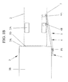
- FIGS. 1A-B and 2A-B illustrate a presently preferred embodiment of a chocking apparatus 1 according to the invention, mounted in the area of a loading dock 3.
- a very schematically illustrated road freight vehicle 2 has been backed up towards the loading dock 3 that is normally provided with rubber bumpers 3D for taking up forces from possible collisions caused by backing,
- a bridge or leveller 3C (indicated only in fig 1A) may be pivotally supported in association with the front side 3A (see fig. 1B) of the loading dock 3 facing the road freight vehicle.
- the chocking apparatus 1 consists of a telescopically extendable and retractable arm 4 that by a first end 4A thereof is carried by a support 7.
- the support 7 is here illustrated in the form of a concrete plinth, the purpose of which is to support the loading dock 3 in the area close to its outer front side 3A.
- an arm bracket 17 is firmly attached to the support 7.
- the arm bracket 17 has a bearing sleeve 18 in which a first portion 19A of an arm holder 19 is journalled for rotation about a first vertical axis P1, see especially figs. 2A and 2B.
- a second portion 19B of the arm holder 19 is in turn pivotally connected to the first arm holder portion 19A, for pivoting about a second horizontal axis P2, and is on its part firmly connected to the first end 4A of the arm 4.
- the arm 4 is adjustable about the first and second axes P1 and P2, respectively, for positioning the arm in an active and an inactive position, respectively, as will be described more closely below.
- the telescopically extendable/retractable arm 4 consists of first and second tubes or pipes 14 and 15, respectively, that are positioned one in the other so that they are telescopically displaceable.
- the arm 4 comprises a first outer tube 14 that forms the first stationary supported end 4A of the arm and that displaceably receives a second, inner tube 15 forming a free second end 4B of the arm.
- an engagement means 5 that is intended to releasably engage a part that is fixed to the vehicle 2.
- the engagement means 5 comprises a chock 6 having a generally curved or bow shaped surface 6A that is intended to be brought into contact with a vehicle wheel 2A in order to block it.
- a modified embodiment of the engagement means will be described more closely below, in association with figs. 3A and 3B.
- a hydraulic piston and cylinder assembly 16 is received in the first tube 14 in order to provide for the displacement between the tubes 14, 15.
- the piston and cylinder assembly 16 is arranged so that its cylinder 16B protrudes through the open first end 4A of the arm 4 and with its rear end is connected to the second arm holder portion 19B.
- the piston rod 16A of the piston and cylinder assembly 16 is connected to the second tube 15.
- No hydraulic connections or control means for operating the piston and cylinder assembly 16 are illustrated on the drawings, since the practical design thereof does not form any part of the actual invention.
- the first outer tube 14 is provided with a first handle 10A, and a second handle 10B is provided in the area of the second free end 4B of the arm 4.
- the second handle may be provided at an outer end of the inner tube 15 and/or at the engagement means 5.
- the first and second handles 10A and 10B, respectively, are both formed as a loop to provide a good grip for one or two hands.
- Figs. 3A and 3B illustrate in detail a modified or supplemented embodiment of the engagement means 5 that is provided at the second end 4B of the ann 4 that is telescopically extendable and retractable, respectively.
- the engagement means 5 consists of a generally wedge shaped chock 6 that is intended for engaging one of the wheels 2A of the vehicle and that is provided with a curved engagement surface 6A that is intended to be brought into direct engagement with the circumference of a vehicle wheel 2A.
- the curved surface 6A of the chock 6 has a larger radius than that of a vehicle wheel with which it is intended to cooperate, to provide a secure contact therebetween.
- the chock 6 has a substantially planar bottom surface 6B that in the active position of the chocking apparatus 5 is intended to rest substantially flat on the truck parking surface 20.
- the chock 6 is capable of limited pivotal movement about an axis P3.
- the chock does normally not have to be pivotal in a larger area than approximately 5°.
- the pivoting is achieved by means of a pin 5B that is fixed to the chock and that is pivotally journalled in a bearing sleeve 5A carried at the second end 4B of the arm 4.
- the bottom surface 6B of the chock 6 is extended by a portion 6C on its side that in the active position faces the loading dock 3, and between the extended portion 6C and the curved surface 6A there is provided a bracing iron 26.
- This will have the result that in the below described engagement position the wheel 2A of the vehicle 2 will be positioned on the extended portion 6C of the bottom surface 6B, so that the weight of the road freight vehicle is used in a very effective way to maintain the chock 6 in position.
- a side stop 9 that consists of a stop plate 9A.
- the stop plate is supported on a shaft 9B that is displaceably supported in the chock 6.
- the side stop 9 is adjustable in a direction S, towards and away from, respectively, the curved surface 6A, so that it may be brought into engagement with the side of a vehicle wheel 2A.
- the adjustment of the side stop 9 is here achieved by means of a series of holes 9C being provided in the displaceable shaft 9B.
- a pin 9D that is attached to the chock 6 is insertable into said holes in order to lock the side stop 9 in the desired position.
- this side stop 9 is to prevent the torque resulting from the later described activation of the chocking apparatus 1 from causing an undesirable displacement or twisting of the chock.
- the chock 6 may also, in a manner that is not specifically disclosed, be capable of limited pivotal movement about a further axis P4, indicated in fig. 3B. The object thereof is to bring the chock 6 to engage the vehicle wheel 2B in a straight position, irrespective of how far the arm 4 is extended in the engagement position, and in other words to prevent the oblique or tilted position of the chock 6 that is disclosed in the alternative engagement position that is illustrated by dash dot lines in figs. 1B and 2B.
- the arm 4 is connected to an adjustable support device 8 at a position between its first and second ends 4A, 4B.
- This support device permits controlled pivoting of the arm about the first and second axes P1, P2.
- the adjustable support device consists of a support leg 8 that by means of a crank 8B is adjustable in height to permit pivoting of the arm 4 about the second horizontal axis P2 and that in a lower end thereof carries a pivoting support wheel 8A for allowing pivoting of the arm 4 about the first vertical axis P1.
- the support leg 8 may preferably be of the type that is used on ordinary one axle trailers. For that reason, the crank mechanism or other parts thereof are not described in detail here.
- arm 4 is arranged so that it is supported on the support 7 with its first end 4A positioned at a substantial distance H2 above the parking surface 20 or driveway.
- the arm 4 is supported on the support 7 with its first end 4A positioned at a distance H2 above the driveway or parking surface 20 that exceeds half the height H1 between the parking surface and the loading plane 3B of the loading dock 3. In this way, the surface directly in front of the loading dock 3 may be kept completely free in the cases where there exists a free space under the loading dock 3.
- the arm 4 in its inactive position, supported on the support leg 8, may be swung completely in under the loading dock 3, as is illustrated with dash dot lines in fig. 1A.
- the arm 4 In the situations where there is no free space available under the loading dock 3 the arm 4 is swung fully in towards the loading dock so that it is extended directly along the front surface 3A of the loading dock and occupies minimum space.
- a vehicle 2 that is to be loaded or unloaded is backed in towards the loading dock 3 until it contacts the rubber bumpers 3D at the loading dock 3.
- the chocking apparatus 1 is then normally in the stowed storage position, with the arm 4 swung in under the loading dock 3, and supported on the support leg S.
- the arm 4 is illustrated in fig. 1A in its position swung fully in under the loading dock 3, but normally it is only swung in a short distance under the dock, so that it is easily reached.
- the arm 4 is raised slightly by means of the support leg 8 so that the engagement means 5 is positioned slightly above the ground surface 20.
- the arm 4 When the length of the arm 4 has been adjusted it is pivoted so that the engagement means 5 is positioned just in front of the vehicle wheel 2A, whereupon it is lowered down by means of the support leg 8 adjustment, so that the chock 6 rests on the ground 20.
- the side stop 9 is adjusted so that its plate 9A engages or is positioned immediately adjacent the side of the vehicle wheel 2A, and then the piston and cylinder assembly 16 is operated again so that the chock 6 is forcefully pulled in towards and, especially in the embodiment with its extended bottom 6C, in under the vehicle wheel 2A.
- the piston and cylinder assembly 16 will normally not have to apply any extreme force, and therefore no overdimensioning thereof or of the arm 4 will be needed.
- a mechanical lock e.g. in the shape of a non-illustrated pin or the like, may be provided between the telescopically displaceable tubes 14 and 15, respectively, of the arm 4.
- the pivotal bridge 3C of the dock or bay 3 may be lowered down so that loading or unloading may be commenced. Since the piston and cylinder assembly 16 continuously pulls the chock 6 towards the dock 3, supported by the weight of the vehicle, the vehicle 2 can be reliably maintained in position against unexpected movements, so that the loading or unloading may be performed very safely.
- the arm 4 is extended a bit by means of the piston and cylinder assembly 16. Then the ann 4 may be swung away to the inactive position again when the support leg has been adjusted upwardly so that the chock 6 hangs free above the ground 20.
- a second embodiment of the chocking apparatus 101 of to the invention In this case the arm 104 is supported directly under the loading surface 3B of the loading dock 3, by a substantially horizontal arm 3E that may be part of an impact protector at the dock 3.
- the controlled support device consists of a balancing spring 108 extended between a bracket 108A at the arm 104 and a bracket 108B at a supporting arm 108C that is firmly attached to the first portion 119A of the arm holder 119.
- Said arm holder 119 corresponds to the one of the first embodiment, except that it is in principle turned upside down..
- balanced out pivoting of the arm 104 about the first and second axes P1, P2 is enabled.
- the balancing spring 108 replaces the support leg of the first embodiment so that maneuvering of the arm 104 between active and inactive positions is entirely independent from the parking surface 20.
- the parking surface will therefore be completely free in the inactive position, even in the case where no free space is available under the loading dock, since the arm may hang freely alongside the loading dock front. Otherwise, the chocking apparatus 101 corresponds to that of the first embodiment.
- fig. 5 illustrates a third embodiment of the chocking apparatus 201 of the invention, where the arm 204 that is telescopically extendable and retractable, respectively, with the first end 204A thereof is supported stationary on the road freight vehicle or truck 2 and where an engagement means 205 at its other end 204B may be brought into releasable engagement with an anchor 206 that is fixed relative to the loading dock 3.
- the first end 204A of the arm 204 is supported at a support 207 that is connected to the frame, not specifically designated, of the vehicle 2. In the inactive position, the arm 204.
- the support device designed as a balancing spring 208, disclosed in association with fig. 4, that here too engages the arm 204 and that has a supporting arm 208C supported at the first portion (not specifically illustrated) of the arm holder 219.
- an engagement means is provided in the other end 204B of the arm 204, said engagement means here being illustrated as a simple hook 205 that in the active position may be hooked onto an anchor 206 formed as a loop attached to the loading dock 3 support 7.
- Maneuvering of the arm 204 is basically performed in the same manner as that described above.
- the advantage of this design is that the loading dock area becomes completely free, and that the design may in principle be employed at all loading and unloading sites without requiring any other rebuilding thereof than the provision of a fixed point or anchor point. In certain cases, this makes up for the disadvantage that each vehicle will have to be provided with a chocking apparatus of its own.
- each truck is provided with a ramp or tail lift that may be raised or lowered and that bridges the distance to the dock.
- the invention may be employed without restriction in all cases, irrespective of the type of device for bridging said distance, and generally by all kinds of loading docks.
- it may in all embodiments be produced having two arms that come into engagement from one side each so that the acting torques cancel each other.
- the invention covers for instance also an embodiment, not illustrated, where the chocking apparatus according to the first embodiment is provided with an engagement means that corresponds to the hook of the third embodiment, and that may be brought into engagement with a fixed anchor, corresponding to the loop of the third embodiment, attached to the frame of the vehicle.
Landscapes
- Engineering & Computer Science (AREA)
- Mechanical Engineering (AREA)
- Transportation (AREA)
- Auxiliary Methods And Devices For Loading And Unloading (AREA)
- Seal Device For Vehicle (AREA)
- Diaphragms For Electromechanical Transducers (AREA)
- Vehicle Body Suspensions (AREA)
- Handcart (AREA)
- Vehicle Cleaning, Maintenance, Repair, Refitting, And Outriggers (AREA)
- Fittings On The Vehicle Exterior For Carrying Loads, And Devices For Holding Or Mounting Articles (AREA)
Claims (12)
- Vorrichtung (1; 101; 201) zur Verhinderung ungewollter Bewegung eines Stra-ßenfrachtfahrzeugs (2) beim Beladen/Entladen an einer Laderampe (3),
dadurch gekennzeichnet,- dass die Vorrichtung einen teleskopisch ausfahrbaren bzw. einfahrbaren Arm (4; 104; 204) aufweist;- dass der teleskopisch ausfahrbare und einfahrbare Arm an einem ersten Ende (4A; 104A; 204A) dieses ortsfest abgestützt ist und in Verbindung mit dem ersten Ende um zwei Achsen (P1; P2) drehbar ist; und- dass der teleskopisch ausfahrbare und einfahrbare Arm an einem zweiten Ende (4B; 104B, 204B) dieses mit einem Eingriffmittel (5; 105; 205) versehen ist;wodurch Schwenken des Arms aus einer Position, in der er aus dem Weg ist, in Sperreingriff des Eingriffsmittels von außerhalb des Wagens ermöglicht wird. - Vorrichtung (1; 101) nach Anspruch 1,
dadurch gekennzeichnet,- dass der teleskopisch ausfahrbare und einfahrbare Arm (4; 104) mit dessen erstem Ende (4A; 104A) in Verbindung mit der Laderampe (3) ortsfest abgestützt wird; und- dass das Eingriffmittel (5; 105) in dessen zweitem Ende (4B; 104B) mit einem an dem Fahrzeug befestigten Teil (2A) lösbar in Eingriff gebracht werden kann. - Vorrichtung (201) nach Anspruch 1,
dadurch gekennzeichnet,- dass der teleskopisch ausfahrbare und einfahrbare Arm (204) mit dessen erstem Ende (204A) ortsfest an dem Fahrzeug (2) abgestützt ist; und- dass das Eingriffmittel (205) in dessen zweitem Ende (204B) mit einem in Bezug auf die Laderampe (3) befestigten Anker (206) lösbar in Eingriff gebracht werden kann. - Vorrichtung (1; 101) nach Anspruch 2,
dadurch gekennzeichnet,
dass das erste Ende (4A; 104A) des teleskopisch ausfahrbaren und einfahrbaren Arms (4; 104) ortsfest auf einer im Zusammenhang mit einer Vorderfläche (3A) der Laderampe (3) vorgesehenen Stütze (7) abgestützt ist, die dem Lastkraftwagen (2) während des Beladens/Entladens gegenüberliegt und dass in Verbindung mit der Stütze der Arm (4; 104) um eine vertikale und eine horizontale Achse (P1 bzw. P2) schwenkbar gelagert ist. - Vorrichtung (1; 101) nach einem der Ansprüche 1, 2 und 4,
dadurch gekennzeichnet,
dass das zweite Ende (4B; 104B) des teleskopisch ausfahrbar und einfahrbaren Arms (4; 104) mit einem Eingriffmittel (5; 105) versehen ist, umfassend einen im Wesentlichen keilförmigen Bremsklotz (6; 106), der zum Ineinadergreifen mit einem Fahrzeugrad (2A) bestimmt ist, und dass der Bremsklotz in der Lage ist begrenzt um zumindest eine Achse (P3, P4) zu schwenken. - Vorrichtung (1; 101; 201) nach einem der Ansprüche 1 - 5,
dadurch gekennzeichnet,
dass der teleskopisch ausfahrbare und einfahrbare Arm (4; 104; 204) aus ersten und zweiten Rohren (14 bzw. 15) besteht, die teleskopisch ineinander verschiebbar sind, und dass eine hydraulische Kolben- und Zylinderanordnung (16) in dem ersten Rohr (14) aufgenommen ist und dessen Zylinder (16B) bzw. dessen Kolbenstange (16A) mit den ersten bzw. zweiten Rohren verbunden ist. - Vorrichtung (1; 101; 201) nach einem der Ansprüche 1-6,
dadurch gekennzeichnet,
dass in einer Position zwischen seinen ersten und zweiten Enden (4A; 104A; 204A; 4B; 104B; 204B) der teleskopisch ausfahrbare und einfahrbare Arm (4; 104; 204) mit einer regulierbaren Stützanordnung (8; 108; 208) verbunden ist, die kontrolliertes Schwenken um die ersten und zweiten Achsen (P1, P2) ermöglicht. - Vorrichtung (1) nach Anspruch 7,
dadurch gekennzeichnet,
dass die regulierbare Stützanordnung einen Stützschenkel (8) aufweist, der höhenverstellbar ist, um Schwenken des Arms (4) um eine zweite horizontale Achse (P2) zu ermöglichen und dass ein unteres Ende dieses ein schwenkbares Stützrad (8A) trägt, um Schwenken des Arms (4) um eine erste vertikale Achse (P1) zu ermöglichen. - Vorrichtung (101; 201) nach Anspruch 7,
dadurch gekennzeichnet,
dass die regulierbare Stützanordnung eine Stabilisierungsfeder (108; 208) aufweist, die in eine Klammer (108A; 208A) an dem Arm (104; 204) eingreift, um ausbalanciertes Schwenken des Arms (104) um die ersten und zweiten Achsen (P1, P2) zu ermöglichen. - Vorrichtung (1; 101) nach Anspruch 5 und einem der Ansprüche 6-9,
dadurch gekennzeichnet,
dass der Bremsklotz (6; 106) eine zylindrisch gewölbte Fläche (6A; 106A) aufweist, die geeignet ist, um in den Umfang des Fahrzeugrads (2A) einzugreifen und einen Seitenstopp (9; 109), der auf einer Seite der zylindrisch gewölbten Fläche vorgesehen ist und der in eine Richtung (S) hin zu bzw. weg von der zylindrisch gewölbten Fläche einstellbar ist, um in die Seite eines Fahrzeugrads (2A) einzugreifen. - Vorrichtung (1, 101) nach einem der Ansprüche 2 und 4-9,
dadurch gekennzeichnet,
dass der teleskopisch ausfahrbare und einfahrbare Arm (4; 104) auf der Stütze (7) abgestützt ist, wobei sein erstes Ende (4A; 104A) in einem beträchtlichen Abstand (H2) über einer Parkfläche (20) des Fahrzeugs (2) positioniert ist. - Vorrichtung (1; 101) nach Anspruch 11,
dadurch gekennzeichnet,
dass der Arm (4; 104) auf der Stütze (7) abgestützt ist, wobei sein erstes Ende (4A; 104A) in einem Abstand (H2) über der Parkfläche (20) des Fahrzeugs positioniert ist, die die halbe Höhe (H1) zwischen der Parkfläche des Fahrzeugs und einer Ladefläche (3B) der Laderampe (3) übersteigt.
Applications Claiming Priority (3)
| Application Number | Priority Date | Filing Date | Title |
|---|---|---|---|
| SE0300023 | 2003-01-10 | ||
| SE0300023A SE524657C2 (sv) | 2003-01-10 | 2003-01-10 | Blokeringsanordning |
| PCT/SE2004/000009 WO2004078618A1 (en) | 2003-01-10 | 2004-01-08 | Chocking apparatus |
Publications (2)
| Publication Number | Publication Date |
|---|---|
| EP1594775A1 EP1594775A1 (de) | 2005-11-16 |
| EP1594775B1 true EP1594775B1 (de) | 2006-12-13 |
Family
ID=20290072
Family Applications (1)
| Application Number | Title | Priority Date | Filing Date |
|---|---|---|---|
| EP04700804A Expired - Lifetime EP1594775B1 (de) | 2003-01-10 | 2004-01-08 | Blockiervorrichtung |
Country Status (7)
| Country | Link |
|---|---|
| US (1) | US7537095B2 (de) |
| EP (1) | EP1594775B1 (de) |
| AT (1) | ATE348061T1 (de) |
| CA (1) | CA2512909C (de) |
| DE (1) | DE602004003678T2 (de) |
| SE (1) | SE524657C2 (de) |
| WO (1) | WO2004078618A1 (de) |
Families Citing this family (26)
| Publication number | Priority date | Publication date | Assignee | Title |
|---|---|---|---|---|
| WO2005121509A1 (en) | 2004-06-14 | 2005-12-22 | Gas Turbine Efficiency Ab | System and devices for collecting and treating waste water from engine washing |
| US8307956B2 (en) | 2007-07-25 | 2012-11-13 | Rite-Hite Holding Corporation | Wheel chock system |
| US8464846B2 (en) * | 2008-03-04 | 2013-06-18 | Rite-Hite Holding Corporation | Restraining arms for wheel chocks |
| US7914042B2 (en) * | 2008-05-13 | 2011-03-29 | Rite-Hite Holding Corporation | Support frame vehicle restraints |
| US8465245B2 (en) * | 2009-04-08 | 2013-06-18 | Rite-Hite Holding Corporation | Wheel restraint systems |
| US20110100765A1 (en) * | 2009-11-03 | 2011-05-05 | Bird Steve K | Wheel chock having a roller assist |
| US8869948B2 (en) | 2009-12-01 | 2014-10-28 | 4Front Engineered Solutions, Inc. | Wheel chocks and associated methods and systems |
| US8528929B2 (en) * | 2010-01-21 | 2013-09-10 | Midwest Industrial Door, Inc. | Trailer docking repositionable support |
| CA2694436A1 (en) * | 2010-02-23 | 2011-08-23 | 9172-9863 Quebec Inc. | Improved chock system |
| CA3184390A1 (en) | 2010-05-19 | 2011-11-24 | Stabilock, LLC | Trailer stabilizer |
| US8286757B2 (en) | 2010-07-09 | 2012-10-16 | Rite-Hite Holding Corporation | Wheel chock system |
| ES2642835T3 (es) | 2013-11-29 | 2017-11-20 | 9172-9863 Québec Inc. | Calzo de rueda |
| CA3223688A1 (en) | 2014-07-01 | 2016-01-01 | Stabilock, LLC | Trailer stabilization and restraint |
| WO2016191882A1 (en) | 2015-06-03 | 2016-12-08 | 9172-9863 Québec Inc. | Bidirectional wheel chock restraint system |
| NL2015971B1 (en) * | 2015-12-16 | 2017-06-30 | Stertil Bv | Blocking device and method for blocking a vehicle and/or entrance to a loading-unloading station, and a dock and distribution center provided therewith. |
| US10329104B2 (en) | 2016-04-04 | 2019-06-25 | Assa Abloy Entrance Systems Ab | Vehicle restraint |
| US9751702B1 (en) | 2016-06-06 | 2017-09-05 | ASSA ABLOY Entrance Systems, Inc. | Wheel chock systems |
| FR3066187B1 (fr) * | 2017-05-12 | 2024-11-01 | Expresso France | Poutre ou rail de guidage, installation de transbordement et procede de mise en oeuvre |
| EP3681771B1 (de) | 2017-09-14 | 2023-06-07 | 9172-9863 Québec Inc. | Radbremsblock mit verriegelungsmechanismus |
| CA3119201A1 (en) * | 2018-11-09 | 2020-05-14 | 9172-9863 Quebec Inc. | Wheel chock handling unit and method |
| US10988329B2 (en) | 2019-02-15 | 2021-04-27 | Assa Abloy Entrance Systems Ab | Vehicle restraint |
| US11618642B2 (en) | 2020-08-20 | 2023-04-04 | Assa Abloy Entrance Systems Ab | Vehicle restraint systems and methods |
| US12297062B1 (en) | 2020-09-21 | 2025-05-13 | The Chamberlain Group Llc. | System and method for restraining a vehicle proximate a loading dock |
| USD987542S1 (en) | 2021-03-22 | 2023-05-30 | 9172-9863 Québec Inc. | Wheel chock |
| USD995394S1 (en) | 2021-03-22 | 2023-08-15 | 9172-9863 Québec Inc. | Wheel chock |
| SE544917C2 (en) * | 2021-05-19 | 2022-12-27 | Bergstroem Lars | Chocking apparatus with slacking surveillance and a method for operating a chocking apparatus |
Family Cites Families (8)
| Publication number | Priority date | Publication date | Assignee | Title |
|---|---|---|---|---|
| US3321046A (en) * | 1966-05-02 | 1967-05-23 | Arley E Cooper | Wheel blocking system |
| USRE33242E (en) * | 1978-05-30 | 1990-06-26 | Abon Corporation | Device for releasably securing a vehicle to an adjacent support |
| US4207019A (en) * | 1978-09-11 | 1980-06-10 | Cone Malcolm S | Truck dock wheel safety chock system |
| DE59003090D1 (de) * | 1990-04-14 | 1993-11-18 | Wijk Nederland | Vorrichtung zum Festhalten eines Fahrzeuges an einer Rampe. |
| NL9302280A (nl) * | 1993-12-28 | 1995-07-17 | Stertil Bv | Wielblokkering. |
| EP0749397B1 (de) * | 1994-03-07 | 2000-04-26 | RITE-HITE HOLDING Corporation | Fahrzeug-betätigte radkeil-positionierungsvorrichtung |
| US5901816A (en) * | 1998-02-19 | 1999-05-11 | Camilleri; Tony C. | Air cylinder-driven wheel chock |
| CA2419680C (en) * | 2002-02-25 | 2010-05-11 | Gaetan Jette | Wheel chock restraint system |
-
2003
- 2003-01-10 SE SE0300023A patent/SE524657C2/sv not_active IP Right Cessation
-
2004
- 2004-01-08 US US10/542,066 patent/US7537095B2/en not_active Expired - Fee Related
- 2004-01-08 WO PCT/SE2004/000009 patent/WO2004078618A1/en not_active Ceased
- 2004-01-08 EP EP04700804A patent/EP1594775B1/de not_active Expired - Lifetime
- 2004-01-08 AT AT04700804T patent/ATE348061T1/de active
- 2004-01-08 DE DE602004003678T patent/DE602004003678T2/de not_active Expired - Lifetime
- 2004-01-08 CA CA2512909A patent/CA2512909C/en not_active Expired - Lifetime
Also Published As
| Publication number | Publication date |
|---|---|
| SE0300023D0 (sv) | 2003-01-10 |
| WO2004078618A1 (en) | 2004-09-16 |
| DE602004003678D1 (de) | 2007-01-25 |
| CA2512909C (en) | 2012-03-20 |
| SE524657C2 (sv) | 2004-09-14 |
| SE0300023L (sv) | 2004-07-11 |
| DE602004003678T2 (de) | 2007-10-04 |
| US20060145460A1 (en) | 2006-07-06 |
| CA2512909A1 (en) | 2004-09-16 |
| US7537095B2 (en) | 2009-05-26 |
| EP1594775A1 (de) | 2005-11-16 |
| ATE348061T1 (de) | 2007-01-15 |
Similar Documents
| Publication | Publication Date | Title |
|---|---|---|
| EP1594775B1 (de) | Blockiervorrichtung | |
| EP2259991B1 (de) | Rückhaltearme für unterlegkeile | |
| EP2285717B1 (de) | Fahrzeugsicherung eines tragrahmens | |
| CA1053293A (en) | Transport vehicle with tiltable chassis | |
| CA2157833C (en) | Transporting apparatus and method | |
| US4289442A (en) | Boom lift load relief | |
| US5324160A (en) | Tiltable trailer for loading, unloading and transporting containers | |
| US20040105746A1 (en) | Wheel lift with laterally movable, rotatable swivel arm wheel scoops | |
| US5683219A (en) | Mechanical truck restraint | |
| US20040013504A1 (en) | Straddle carrier | |
| US5807057A (en) | Transport vehicle for taking up and taking down containers and the like onto or from a loading platform thereof | |
| JPH06508322A (ja) | 地上における航空機の搬送用車両 | |
| US6520472B1 (en) | Container restraint for a parked swap body | |
| US6309165B1 (en) | Leg restraint for a parked swap body container | |
| US6032809A (en) | Apparatus for reducing the axle load of a multiaxle movable telescopic crane | |
| US5845920A (en) | Apparatus for towing a disabled truck tractor | |
| WO2000043302A9 (en) | Container restraint for a parked swap body | |
| US3363914A (en) | Load equalizing device | |
| CA2192726A1 (en) | Longitudinally and vertically adjustable axle assembly | |
| CA2164738C (en) | Wedge support | |
| US6857840B2 (en) | Removable load bed for a vehicle | |
| US4026429A (en) | Method of unloading container from transport vehicle | |
| US4746262A (en) | Apparatus for handling and transporting double frame structures | |
| EP1154911A1 (de) | Fahrzeug zum transport länglicher behälter in waagerechter lage und anordnung mit einer be- und entladestation und ein solches fahrzeug | |
| US3826201A (en) | Portable railway car mover |
Legal Events
| Date | Code | Title | Description |
|---|---|---|---|
| PUAI | Public reference made under article 153(3) epc to a published international application that has entered the european phase |
Free format text: ORIGINAL CODE: 0009012 |
|
| 17P | Request for examination filed |
Effective date: 20050810 |
|
| AK | Designated contracting states |
Kind code of ref document: A1 Designated state(s): AT BE BG CH CY CZ DE DK EE ES FI FR GB GR HU IE IT LI LU MC NL PT RO SE SI SK TR |
|
| AX | Request for extension of the european patent |
Extension state: AL LT LV MK |
|
| DAX | Request for extension of the european patent (deleted) | ||
| GRAP | Despatch of communication of intention to grant a patent |
Free format text: ORIGINAL CODE: EPIDOSNIGR1 |
|
| GRAS | Grant fee paid |
Free format text: ORIGINAL CODE: EPIDOSNIGR3 |
|
| GRAA | (expected) grant |
Free format text: ORIGINAL CODE: 0009210 |
|
| AK | Designated contracting states |
Kind code of ref document: B1 Designated state(s): AT BE BG CH CY CZ DE DK EE ES FI FR GB GR HU IE IT LI LU MC NL PT RO SE SI SK TR |
|
| PG25 | Lapsed in a contracting state [announced via postgrant information from national office to epo] |
Ref country code: SK Free format text: LAPSE BECAUSE OF FAILURE TO SUBMIT A TRANSLATION OF THE DESCRIPTION OR TO PAY THE FEE WITHIN THE PRESCRIBED TIME-LIMIT Effective date: 20061213 Ref country code: SI Free format text: LAPSE BECAUSE OF FAILURE TO SUBMIT A TRANSLATION OF THE DESCRIPTION OR TO PAY THE FEE WITHIN THE PRESCRIBED TIME-LIMIT Effective date: 20061213 Ref country code: RO Free format text: LAPSE BECAUSE OF FAILURE TO SUBMIT A TRANSLATION OF THE DESCRIPTION OR TO PAY THE FEE WITHIN THE PRESCRIBED TIME-LIMIT Effective date: 20061213 Ref country code: IT Free format text: LAPSE BECAUSE OF FAILURE TO SUBMIT A TRANSLATION OF THE DESCRIPTION OR TO PAY THE FEE WITHIN THE PRESCRIBED TIME-LIMIT;WARNING: LAPSES OF ITALIAN PATENTS WITH EFFECTIVE DATE BEFORE 2007 MAY HAVE OCCURRED AT ANY TIME BEFORE 2007. THE CORRECT EFFECTIVE DATE MAY BE DIFFERENT FROM THE ONE RECORDED. Effective date: 20061213 Ref country code: DK Free format text: LAPSE BECAUSE OF FAILURE TO SUBMIT A TRANSLATION OF THE DESCRIPTION OR TO PAY THE FEE WITHIN THE PRESCRIBED TIME-LIMIT Effective date: 20061213 Ref country code: CZ Free format text: LAPSE BECAUSE OF FAILURE TO SUBMIT A TRANSLATION OF THE DESCRIPTION OR TO PAY THE FEE WITHIN THE PRESCRIBED TIME-LIMIT Effective date: 20061213 |
|
| REG | Reference to a national code |
Ref country code: GB Ref legal event code: FG4D |
|
| REG | Reference to a national code |
Ref country code: CH Ref legal event code: EP |
|
| PG25 | Lapsed in a contracting state [announced via postgrant information from national office to epo] |
Ref country code: IE Free format text: LAPSE BECAUSE OF NON-PAYMENT OF DUE FEES Effective date: 20070108 |
|
| REG | Reference to a national code |
Ref country code: IE Ref legal event code: FG4D |
|
| REF | Corresponds to: |
Ref document number: 602004003678 Country of ref document: DE Date of ref document: 20070125 Kind code of ref document: P |
|
| PG25 | Lapsed in a contracting state [announced via postgrant information from national office to epo] |
Ref country code: MC Free format text: LAPSE BECAUSE OF NON-PAYMENT OF DUE FEES Effective date: 20070131 |
|
| PG25 | Lapsed in a contracting state [announced via postgrant information from national office to epo] |
Ref country code: SE Free format text: LAPSE BECAUSE OF FAILURE TO SUBMIT A TRANSLATION OF THE DESCRIPTION OR TO PAY THE FEE WITHIN THE PRESCRIBED TIME-LIMIT Effective date: 20070313 Ref country code: BG Free format text: LAPSE BECAUSE OF FAILURE TO SUBMIT A TRANSLATION OF THE DESCRIPTION OR TO PAY THE FEE WITHIN THE PRESCRIBED TIME-LIMIT Effective date: 20070313 |
|
| PG25 | Lapsed in a contracting state [announced via postgrant information from national office to epo] |
Ref country code: ES Free format text: LAPSE BECAUSE OF FAILURE TO SUBMIT A TRANSLATION OF THE DESCRIPTION OR TO PAY THE FEE WITHIN THE PRESCRIBED TIME-LIMIT Effective date: 20070324 |
|
| REG | Reference to a national code |
Ref country code: CH Ref legal event code: NV Representative=s name: ING. MARCO ZARDI C/O M. ZARDI & CO. S.A. |
|
| PG25 | Lapsed in a contracting state [announced via postgrant information from national office to epo] |
Ref country code: PT Free format text: LAPSE BECAUSE OF FAILURE TO SUBMIT A TRANSLATION OF THE DESCRIPTION OR TO PAY THE FEE WITHIN THE PRESCRIBED TIME-LIMIT Effective date: 20070514 |
|
| ET | Fr: translation filed | ||
| PLBE | No opposition filed within time limit |
Free format text: ORIGINAL CODE: 0009261 |
|
| STAA | Information on the status of an ep patent application or granted ep patent |
Free format text: STATUS: NO OPPOSITION FILED WITHIN TIME LIMIT |
|
| 26N | No opposition filed |
Effective date: 20070914 |
|
| PG25 | Lapsed in a contracting state [announced via postgrant information from national office to epo] |
Ref country code: GR Free format text: LAPSE BECAUSE OF FAILURE TO SUBMIT A TRANSLATION OF THE DESCRIPTION OR TO PAY THE FEE WITHIN THE PRESCRIBED TIME-LIMIT Effective date: 20070314 |
|
| PG25 | Lapsed in a contracting state [announced via postgrant information from national office to epo] |
Ref country code: EE Free format text: LAPSE BECAUSE OF FAILURE TO SUBMIT A TRANSLATION OF THE DESCRIPTION OR TO PAY THE FEE WITHIN THE PRESCRIBED TIME-LIMIT Effective date: 20061213 |
|
| PG25 | Lapsed in a contracting state [announced via postgrant information from national office to epo] |
Ref country code: LU Free format text: LAPSE BECAUSE OF NON-PAYMENT OF DUE FEES Effective date: 20070108 Ref country code: CY Free format text: LAPSE BECAUSE OF FAILURE TO SUBMIT A TRANSLATION OF THE DESCRIPTION OR TO PAY THE FEE WITHIN THE PRESCRIBED TIME-LIMIT Effective date: 20061213 |
|
| PG25 | Lapsed in a contracting state [announced via postgrant information from national office to epo] |
Ref country code: HU Free format text: LAPSE BECAUSE OF FAILURE TO SUBMIT A TRANSLATION OF THE DESCRIPTION OR TO PAY THE FEE WITHIN THE PRESCRIBED TIME-LIMIT Effective date: 20070614 Ref country code: TR Free format text: LAPSE BECAUSE OF FAILURE TO SUBMIT A TRANSLATION OF THE DESCRIPTION OR TO PAY THE FEE WITHIN THE PRESCRIBED TIME-LIMIT Effective date: 20061213 |
|
| REG | Reference to a national code |
Ref country code: CH Ref legal event code: NV Representative=s name: R. A. EGLI & CO. PATENTANWAELTE |
|
| REG | Reference to a national code |
Ref country code: FR Ref legal event code: PLFP Year of fee payment: 12 |
|
| REG | Reference to a national code |
Ref country code: FR Ref legal event code: PLFP Year of fee payment: 13 |
|
| REG | Reference to a national code |
Ref country code: FR Ref legal event code: PLFP Year of fee payment: 14 |
|
| REG | Reference to a national code |
Ref country code: FR Ref legal event code: PLFP Year of fee payment: 15 |
|
| PGFP | Annual fee paid to national office [announced via postgrant information from national office to epo] |
Ref country code: NL Payment date: 20200131 Year of fee payment: 17 Ref country code: DE Payment date: 20200127 Year of fee payment: 17 Ref country code: AT Payment date: 20200129 Year of fee payment: 17 |
|
| PGFP | Annual fee paid to national office [announced via postgrant information from national office to epo] |
Ref country code: BE Payment date: 20200123 Year of fee payment: 17 |
|
| PGFP | Annual fee paid to national office [announced via postgrant information from national office to epo] |
Ref country code: FR Payment date: 20200129 Year of fee payment: 17 |
|
| PGFP | Annual fee paid to national office [announced via postgrant information from national office to epo] |
Ref country code: CH Payment date: 20200428 Year of fee payment: 17 |
|
| REG | Reference to a national code |
Ref country code: DE Ref legal event code: R119 Ref document number: 602004003678 Country of ref document: DE |
|
| REG | Reference to a national code |
Ref country code: CH Ref legal event code: PL |
|
| REG | Reference to a national code |
Ref country code: NL Ref legal event code: MM Effective date: 20210201 |
|
| REG | Reference to a national code |
Ref country code: AT Ref legal event code: MM01 Ref document number: 348061 Country of ref document: AT Kind code of ref document: T Effective date: 20210108 |
|
| REG | Reference to a national code |
Ref country code: BE Ref legal event code: MM Effective date: 20210131 |
|
| PG25 | Lapsed in a contracting state [announced via postgrant information from national office to epo] |
Ref country code: AT Free format text: LAPSE BECAUSE OF NON-PAYMENT OF DUE FEES Effective date: 20210108 Ref country code: NL Free format text: LAPSE BECAUSE OF NON-PAYMENT OF DUE FEES Effective date: 20210201 Ref country code: FR Free format text: LAPSE BECAUSE OF NON-PAYMENT OF DUE FEES Effective date: 20210131 |
|
| PG25 | Lapsed in a contracting state [announced via postgrant information from national office to epo] |
Ref country code: LI Free format text: LAPSE BECAUSE OF NON-PAYMENT OF DUE FEES Effective date: 20210131 Ref country code: CH Free format text: LAPSE BECAUSE OF NON-PAYMENT OF DUE FEES Effective date: 20210131 Ref country code: DE Free format text: LAPSE BECAUSE OF NON-PAYMENT OF DUE FEES Effective date: 20210803 |
|
| PG25 | Lapsed in a contracting state [announced via postgrant information from national office to epo] |
Ref country code: BE Free format text: LAPSE BECAUSE OF NON-PAYMENT OF DUE FEES Effective date: 20210131 |
|
| PGFP | Annual fee paid to national office [announced via postgrant information from national office to epo] |
Ref country code: FI Payment date: 20230414 Year of fee payment: 20 |
|
| PGFP | Annual fee paid to national office [announced via postgrant information from national office to epo] |
Ref country code: GB Payment date: 20230413 Year of fee payment: 20 |
|
| REG | Reference to a national code |
Ref country code: GB Ref legal event code: PE20 Expiry date: 20240107 |
|
| PG25 | Lapsed in a contracting state [announced via postgrant information from national office to epo] |
Ref country code: GB Free format text: LAPSE BECAUSE OF EXPIRATION OF PROTECTION Effective date: 20240107 |